EP3732954B1 - Separating device - Google Patents
Separating device Download PDFInfo
- Publication number
- EP3732954B1 EP3732954B1 EP20151419.7A EP20151419A EP3732954B1 EP 3732954 B1 EP3732954 B1 EP 3732954B1 EP 20151419 A EP20151419 A EP 20151419A EP 3732954 B1 EP3732954 B1 EP 3732954B1
- Authority
- EP
- European Patent Office
- Prior art keywords
- separating
- separating device
- sections
- face
- feed drum
- Prior art date
- Legal status (The legal status is an assumption and is not a legal conclusion. Google has not performed a legal analysis and makes no representation as to the accuracy of the status listed.)
- Active
Links
- 239000000463 material Substances 0.000 claims description 29
- 239000011248 coating agent Substances 0.000 claims description 25
- 238000000576 coating method Methods 0.000 claims description 25
- 238000005520 cutting process Methods 0.000 claims description 16
- 238000003466 welding Methods 0.000 claims description 9
- 239000011156 metal matrix composite Substances 0.000 claims description 4
- 229910000831 Steel Inorganic materials 0.000 claims description 3
- 239000010959 steel Substances 0.000 claims description 3
- 230000000694 effects Effects 0.000 description 5
- 238000009826 distribution Methods 0.000 description 3
- 239000011159 matrix material Substances 0.000 description 3
- PXHVJJICTQNCMI-UHFFFAOYSA-N Nickel Chemical compound [Ni] PXHVJJICTQNCMI-UHFFFAOYSA-N 0.000 description 2
- 230000008021 deposition Effects 0.000 description 2
- 238000004519 manufacturing process Methods 0.000 description 2
- 238000000034 method Methods 0.000 description 2
- 238000000926 separation method Methods 0.000 description 2
- 239000010902 straw Substances 0.000 description 2
- UONOETXJSWQNOL-UHFFFAOYSA-N tungsten carbide Chemical compound [W+]#[C-] UONOETXJSWQNOL-UHFFFAOYSA-N 0.000 description 2
- 229910000640 Fe alloy Inorganic materials 0.000 description 1
- 229910000990 Ni alloy Inorganic materials 0.000 description 1
- 238000004140 cleaning Methods 0.000 description 1
- 238000011161 development Methods 0.000 description 1
- 230000018109 developmental process Effects 0.000 description 1
- 238000004898 kneading Methods 0.000 description 1
- 229910052759 nickel Inorganic materials 0.000 description 1
- 239000000843 powder Substances 0.000 description 1
- 238000009420 retrofitting Methods 0.000 description 1
- 230000000630 rising effect Effects 0.000 description 1
- 230000007704 transition Effects 0.000 description 1
- 238000011144 upstream manufacturing Methods 0.000 description 1
Images


Classifications
-
- A—HUMAN NECESSITIES
- A01—AGRICULTURE; FORESTRY; ANIMAL HUSBANDRY; HUNTING; TRAPPING; FISHING
- A01F—PROCESSING OF HARVESTED PRODUCE; HAY OR STRAW PRESSES; DEVICES FOR STORING AGRICULTURAL OR HORTICULTURAL PRODUCE
- A01F12/00—Parts or details of threshing apparatus
- A01F12/30—Straw separators, i.e. straw walkers, for separating residual grain from the straw
- A01F12/39—Straw separators, i.e. straw walkers, for separating residual grain from the straw with straw carriers in the form of rotors or drums
-
- A—HUMAN NECESSITIES
- A01—AGRICULTURE; FORESTRY; ANIMAL HUSBANDRY; HUNTING; TRAPPING; FISHING
- A01F—PROCESSING OF HARVESTED PRODUCE; HAY OR STRAW PRESSES; DEVICES FOR STORING AGRICULTURAL OR HORTICULTURAL PRODUCE
- A01F7/00—Threshing apparatus
- A01F7/02—Threshing apparatus with rotating tools
- A01F7/06—Threshing apparatus with rotating tools with axles in line with the feeding direction ; Axial threshing machines
-
- A—HUMAN NECESSITIES
- A01—AGRICULTURE; FORESTRY; ANIMAL HUSBANDRY; HUNTING; TRAPPING; FISHING
- A01F—PROCESSING OF HARVESTED PRODUCE; HAY OR STRAW PRESSES; DEVICES FOR STORING AGRICULTURAL OR HORTICULTURAL PRODUCE
- A01F12/00—Parts or details of threshing apparatus
- A01F12/10—Feeders
-
- A—HUMAN NECESSITIES
- A01—AGRICULTURE; FORESTRY; ANIMAL HUSBANDRY; HUNTING; TRAPPING; FISHING
- A01F—PROCESSING OF HARVESTED PRODUCE; HAY OR STRAW PRESSES; DEVICES FOR STORING AGRICULTURAL OR HORTICULTURAL PRODUCE
- A01F7/00—Threshing apparatus
- A01F7/02—Threshing apparatus with rotating tools
- A01F7/06—Threshing apparatus with rotating tools with axles in line with the feeding direction ; Axial threshing machines
- A01F7/067—Threshing apparatus with rotating tools with axles in line with the feeding direction ; Axial threshing machines with material-flow influencing means
-
- A—HUMAN NECESSITIES
- A01—AGRICULTURE; FORESTRY; ANIMAL HUSBANDRY; HUNTING; TRAPPING; FISHING
- A01D—HARVESTING; MOWING
- A01D41/00—Combines, i.e. harvesters or mowers combined with threshing devices
- A01D41/12—Details of combines
Definitions
- the present invention relates to a separating device according to the preamble of claim 1.
- the present invention also relates to a combine harvester with a separating device.
- a separator and a combine harvester with a separator are from EP 2 965 614 B1 known.
- the separating device comprises an inlet head housing, a feed drum and two axial separator rotors, one end of which protrudes in sections into the inlet head housing.
- the harvested crop is fed in by the tangentially conveying feed drum, which is arranged above the inlet section in front of the openings of the axial separator rotors.
- the inlet head housing has a flat inlet section that extends across the width of the respective axial separator rotor, between which a ramp-shaped housing section is arranged that extends axially parallel to the conveying direction of the axial separator rotors, which divides a crop flow supplied by the feed drum, which consists mainly of stalks, stalks or The like is supported in the axial separator rotors to be supplied partial flows.
- At least one separating element made of a first material is arranged on the ramp-shaped housing section and extends in sections in the circumferential direction of the feed drum.
- the ramp-shaped housing section rising in the vertical direction and the separating element arranged thereon have a concave profile and serve to support the separation or distribution of the crop being fed in, in order to achieve uniform feeding of the crop to the axial separator rotors.
- the separating element acts as a cutting blade on the harvested crop flowing over it, ie it cuts through or cuts it as it passes the separating element.
- the downtime in particular of the separating element, which protrudes in sections into the crop flow, is limited due to the abrasive effect of the crop flowing over.
- this object is achieved by a separating device according to independent claim 1 .
- a separating device comprising an inlet head housing, a feed drum and two axial separator rotors, one end of which protrudes in sections into the inlet head housing, with the inlet head housing each having a flat inlet section extending across the width of the respective axial separator rotor, between which a ramp-shaped , a housing section that extends axially parallel to the conveying direction of the axial separator rotors is arranged, which supports a division of a crop flow supplied by the feed drum into partial flows to be supplied to the axial separator rotors, wherein the ramp-shaped housing section is assigned at least one separating element consisting of at least one first material, the at least one separating element having a Base body which extends perpendicularly to the surface of the housing section and has an end face designed in sections as a cutting edge, a coating made of a more wear-resistant second material being arranged at least in sections on the end face and running essentially centrally in the longitudinal direction of the
- the application of the coating takes place essentially as a strip or band-shaped section, the width of which is less than the total width of the end face. This ensures that during operation of the separating device to the coating adjacent areas of the end face, which consist of the first material, are exposed to greater wear, ie are abraded to a greater extent. This results in the effect of a symmetrical, self-sharpening cutting edge geometry.
- the geometry and/or the service life of the cutting edge can be influenced by varying the first material. For example, the use of a softer first material for the base body can lead to a sharper cutting edge, since the surfaces located laterally next to the cutting edge wear faster than the end face, which is provided at least in sections with a coating of the more wear-resistant second material.
- the separating element can be detachably arranged on the housing section. In this way, a simple exchange or a simple retrofitting of the separating element can be achieved.
- the first material may be high strength steel and the second material may be a metal matrix composite.
- the metal matrix composite material may be, for example, tungsten carbide or fused tungsten carbide with an iron alloy matrix, a nickel alloy matrix or a nickel matrix.
- the coating can preferably be applied by means of build-up welding.
- the coating can be applied by means of laser deposition welding or plasma powder deposition welding.
- Laser build-up welding can be used with particular preference, since with laser build-up welding there is less heat input into the separating element to be coated than in conventional build-up welding.
- the end face can have an essentially wave-shaped profile.
- the end face can have a substantially sawtooth-shaped profile.
- the cutting or influence the separation effect Due to the interchangeability, the separating element can be exchanged depending on the crop to be processed.
- the coating can preferably extend over the entire longitudinal extent of the end face. This is advantageous, inter alia, because of production engineering aspects. In addition, this creates a continuous, wear-resistant cutting edge on the face.
- the end face can have an essentially jagged or sawtooth-shaped profile, the jagged or sawtooth-shaped profile being formed of essentially horizontal sections running alternately in the longitudinal direction of the separating element and vertical sections extending essentially perpendicular thereto.
- the jagged or sawtooth-shaped profile acts more aggressively on the harvested crop.
- the coating can only be applied to the vertical sections that extend essentially perpendicularly to the horizontal sections. This reduces the outlay in terms of production technology for the coating. Only the end faces of the vertical sections of the separating element can be coated which, corresponding to the direction of rotation of the feed drum, are brought into separating or cutting engagement with the crop flow to be conveyed, so that these are exposed to the greatest wear.
- the horizontal sections are subject to significantly less wear, so that if a suitable first material is selected, a sufficient service life can be achieved here even without coating them with the second material.
- the feed drum can be provided in the area of the ramp-shaped housing section with a plurality of separating elements arranged one behind the other in the circumferential direction.
- the separating elements are arranged in a central area of the feed drum. This allows the cutting or separating effect by interacting with the separating element arranged on the housing section.
- two separating elements of the feed drum can be arranged in pairs next to one another, with the separating elements of each pair being arranged running towards one another in the direction of rotation of the feed drum.
- the wedge shape formed by the arrangement of a pair of separating elements means that the separating element on the housing section acts as a counter-knife for the respective tip of the pair of separating elements on the rotating feed drum.
- the object is achieved by a combine harvester with a separating device, which is characterized in that the separating device is designed according to one of the preceding claims.
- the separating device can be provided as a separating device working according to the axial flow principle, which is preceded by a threshing device working according to the tangential flow principle.
- an embodiment of the separating device can be designed as a threshing and separating device working according to the axial flow principle, in which the threshing process and the separating process are carried out together by suitably designed axial separating rotors.
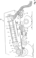
- the representation in 1 shows a schematic partial view of a combine harvester 20.
- crop material to be processed is picked up by an attachment and fed to a tangentially acting threshing device 2 by a conveying device 1 designed as an inclined conveyor, which is only partially shown.
- the threshing device 2 comprises at least one threshing drum 3 with an axis oriented transversely to the direction of travel of the combine harvester 20, which is surrounded by a threshing concave 4 on part of its circumference.
- a partial flow of the crop processed by the threshing device 2 passes through openings in the concave 4 onto a conveyor floor 11 located underneath.
- a larger partial flow of the harvested crop is passed between the threshing drum 3 and the concave 4 and fed with the support of a guide drum or feed drum 5 to a separating device 6 that operates according to the axial flow principle.
- the separating device 6 shown schematically is designed as at least one cylindrical housing 7 which is open at its ends and in which two axial separating rotors 8 designed as conveying elements are mounted so that they can be driven in rotation over its entire length. Due to the counter-rotating rotation of the axial separator rotors 8, the harvested crop is conveyed through the separator device 6 on a helical path.
- the coarse straw largely freed from the grain during the passage through the separating device 6 is ejected at the rear end of the separating device 6 and falls to the ground via a chute 13 or is fed to a chopping and distribution device 21 .
- the threshing device 2 and the separating device 6 thus form a first separating stage or separating stage.
- a second separating stage or cleaning stage is essentially made up of a fan 14 and a group of sieve decks 15 located in the wind flow of the fan 14, which are driven to oscillate in a frame (not shown) and are charged with the pre-cleaned partial flow of harvested material coming from the conveyor floor 11.
- the grain contained in the pre-cleaned partial flow trickles through the oscillating sieve floors 15 onto a sloping first guide floor 16.
- a screw conveyor 19 At the lower end of the guide floor 16 there is a screw conveyor 19 which conveys the grain to an elevator and through this into a grain tank.
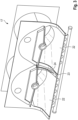
- In 2 1 is an isometric view of the inlet head housing 17 of the separator apparatus. while showing 2 the inlet head housing 17 with the upstream feed drum, which rotates about an axis 25 in the direction of rotation DR.
- the representation in 3 shows an isometric view of the inlet head housing 17 without the feed drum 5.
- the inlet head housing 17 has a flat inlet section 22 which extends over the width of the corresponding axial separator rotor 8 and runs below the feed drum 5 in sections.
- a ramp-shaped housing section 23 is located between the two inlet sections 21.
- the ramp-shaped housing section 23 has a substantially concave profile and extends in sections in the circumferential direction of the feed drum 5.
- a substantially blade-shaped separating element 24 is arranged on the housing section 23.
- the separating element 24 extends essentially in the longitudinal direction of the housing section 23 , with its contour essentially corresponding to that of the housing section 23 .
- the separating element 24 is preferably arranged detachably on the housing section 23 so that it can be easily replaced, for example due to wear or to adapt to different types of harvested crops.
- the separating element 24 can be screwed onto the inlet head housing 17 .
- the feed drum 5 is provided with a plurality of separating elements 27 arranged one behind the other in the circumferential direction.
- the feed drum 5 has guide plates 26 arranged or designed in a V-shape in its central region.
- the guide plates 26 are arranged one behind the other as seen in the circumferential direction of the feed drum 5 and extend outwards in the radial direction, starting from the lateral surface of the feed drum 5 .
- the separating elements 27 are arranged on the outer sides of the guide plates 26 .
- the separating element 24 interacts with the separating elements 27 of the rotating feed drum 5 in order to separate and divide crops.
- the stationary separating element 24 represents a type of counter knife for the separating knife 27 on the guide plates 26 of the feed drum 5.
- the separating element 24 has a curved shape which essentially corresponds to the course of the ramp-shaped housing section 23 on which the separating element 24 is fastened.
- the separating element 24 has a base body 28, which extends perpendicular to the surface of the ramp-shaped housing section 23.
- the base body 28 has an end face 29 designed in sections as a cutting edge, which acts on crops fed in from the feed drum 5 .
- the base body 28 consists of a first material, preferably a high-strength steel.
- a coating 30 made of a second material is arranged at least in sections on the end face 29 and runs essentially centrally in the longitudinal direction of the end face 29 .
- the application of the coating 30 takes place essentially as a strip or band-shaped section, the width of which is less than the overall width of the end face 29 .
- adjacent sections or areas of the end face 29 are formed which are made of the first material.
- the second material is characterized by a higher wear resistance than the first material.
- the second material is a metal matrix composite.
- the coating 30 made of the second material is applied by build-up welding, in particular by laser build-up welding.
- the end face 29 has an essentially wave-shaped profile.
- the end face 29 can also be designed with a sawtooth-shaped profile.
- the coating 30 extends completely in the longitudinal direction of the separating element 24 over its end face 29. This ensures that during operation of the separating device 6, the sections or areas of the end face 29 adjacent to the coating 30, which are made of the first material exist, are exposed to greater wear, i.e. are abraded to a greater extent. This results in the effect of a symmetrical, self-sharpening cutting edge geometry.
- FIG 5 a perspective view of an embodiment of the separating element 27 arranged on the feed drum 5 is shown schematically.
- the basic structure of the separating element 27 arranged on the feed drum 5 essentially corresponds to that arranged on the ramp-shaped housing section Separating element 24, so that the reference numerals are the same for functionally identical elements.
- the separating element 27 also has a curved shape.
- the separating element 27 has an end face 29 designed as a cutting edge.
- the end face 29 has an essentially jagged or stepped profile, with the jagged or stepped profile being formed from essentially horizontal sections 31 running alternately in the longitudinal direction of the separating element 27 and vertical sections 32 extending perpendicular thereto. At the beginning of the profile of the separating element 27 there is always a vertical section 32.
- the vertical sections 32 extend radially to the lateral surface of the feed drum 5.
- the application of the coating 30 only on the vertical sections 32 of the separating element 27, which corresponds to the direction of rotation DR of the feed drum 5 are brought into separating or cutting engagement with the crop flow to be conveyed, so that these are exposed to the greatest wear, can be sufficient for an increased service life.
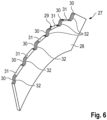
- FIG. 6 shows schematically a perspective view of a further embodiment of the separating element 27 according to FIG figure 5 . It is provided that the coating 30 extends completely over the respective vertical section 32 and in sections along the horizontal section 31 adjoining the respective vertical section 32 . The coating 30 is applied in particular in the area in and after the transition between the vertical section 32 and the subsequent horizontal section 31 .
- the configuration of the separating elements 27 of the feed drum 5 according to the embodiments described above can also be transferred to the separating element 24 on the ramp-shaped housing section 23 .
Description
Die vorliegende Erfindung betrifft eine Abscheidevorrichtung gemäß dem Oberbegriff des Anspruches 1. Weiterhin betrifft die vorliegende Erfindung einen Mähdrescher mit einer Abscheidevorrichtung.The present invention relates to a separating device according to the preamble of claim 1. The present invention also relates to a combine harvester with a separating device.
Eine Abscheidevorrichtung sowie ein Mähdrescher mit einer Abscheidevorrichtung sind aus der
Somit ist es Aufgabe der vorliegenden Erfindung, eine Abscheidevorrichtung der eingangs genannten Art weiterzubilden, die sich durch eine höhere Standzeit auszeichnet.It is therefore the object of the present invention to further develop a separating device of the type mentioned at the outset, which is characterized by a longer service life.
Diese Aufgabe wird erfindungsgemäß durch eine Abscheidevorrichtung gemäß dem unabhängigen Anspruch 1 gelöst.According to the invention, this object is achieved by a separating device according to independent claim 1 .
Vorteilhafte Weiterbildungen sind Gegenstand der Unteransprüche.Advantageous developments are the subject of the subclaims.
Gemäß dem Anspruch 1 wird eine Abscheidevorrichtung vorgeschlagen, umfassend ein Einlaufkopfgehäuse, eine Zuführtrommel sowie zwei Axialabscheiderotoren, die mit einem Ende abschnittsweise in das Einlaufkopfgehäuse hineinragen, wobei das Einlaufkopfgehäuse jeweils einen sich über die Breite des jeweiligen Axialabscheiderotors erstreckenden flächigen Einlaufabschnitt aufweist, zwischen denen ein rampenförmiger, sich achsparallel zur Förderrichtung der Axialabscheiderotoren erstreckender Gehäuseabschnitt angeordnet ist, welcher eine Aufteilung eines von der Zuführtrommel zugeführten Erntegutstromes in den Axialabscheiderotoren zuzuführende Teilströme unterstützt, wobei dem rampenförmigen Gehäuseabschnitt zumindest ein aus zumindest einem ersten Material bestehendes Trennelement zugeordnet ist, wobei das zumindest eine Trennelement einen Grundkörper, der sich senkrecht zur Oberfläche des Gehäuseabschnitts erstreckt, und eine abschnittsweise als Schneide ausgebildete Stirnfläche aufweist, wobei auf der Stirnfläche zumindest abschnittsweise eine Beschichtung aus einem verschleißfesteren zweiten Material angeordnet ist, die im Wesentlichen mittig in Längsrichtung der Stirnfläche verläuft. Die Aufbringung der Beschichtung erfolgt dabei im Wesentlichen als streifen- oder bandförmiger Abschnitt, dessen Breite geringer als die Gesamtbreite der Stirnfläche ist. Hierdurch wird erreicht, dass im laufenden Betrieb der Abscheidevorrichtung die zu der Beschichtung benachbarten Bereiche der Stirnfläche, die aus dem ersten Material bestehen, einem größeren Verschleiß ausgesetzt sind, d.h. stärker abgeschliffen werden. Daraus resultiert der Effekt einer symmetrischen, selbstschärfenden Schneidengeometrie. Weiterhin kann durch eine Variation des ersten Materials die Geometrie und/oder die Standzeit der Schneide beeinflusst werden. So kann beispielsweise die Verwendung eines weicheren ersten Materials für den Grundkörper zu einer spitzeren Schneide führen, da sich die seitlich neben der Schneide befindliche Flächen schneller verschleißen als die Stirnfläche, die zumindest abschnittsweise mit einer Beschichtung aus dem verschleißfesteren zweiten Material versehen ist.According to Claim 1, a separating device is proposed, comprising an inlet head housing, a feed drum and two axial separator rotors, one end of which protrudes in sections into the inlet head housing, with the inlet head housing each having a flat inlet section extending across the width of the respective axial separator rotor, between which a ramp-shaped , a housing section that extends axially parallel to the conveying direction of the axial separator rotors is arranged, which supports a division of a crop flow supplied by the feed drum into partial flows to be supplied to the axial separator rotors, wherein the ramp-shaped housing section is assigned at least one separating element consisting of at least one first material, the at least one separating element having a Base body which extends perpendicularly to the surface of the housing section and has an end face designed in sections as a cutting edge, a coating made of a more wear-resistant second material being arranged at least in sections on the end face and running essentially centrally in the longitudinal direction of the end face. The application of the coating takes place essentially as a strip or band-shaped section, the width of which is less than the total width of the end face. This ensures that during operation of the separating device to the coating adjacent areas of the end face, which consist of the first material, are exposed to greater wear, ie are abraded to a greater extent. This results in the effect of a symmetrical, self-sharpening cutting edge geometry. Furthermore, the geometry and/or the service life of the cutting edge can be influenced by varying the first material. For example, the use of a softer first material for the base body can lead to a sharper cutting edge, since the surfaces located laterally next to the cutting edge wear faster than the end face, which is provided at least in sections with a coating of the more wear-resistant second material.
Insbesondere kann das Trennelement lösbar an dem Gehäuseabschnitt angeordnet sein. Hierdurch lässt sich ein einfacher Austausch oder ein einfaches Nachrüsten des Trennelementes erreichen.In particular, the separating element can be detachably arranged on the housing section. In this way, a simple exchange or a simple retrofitting of the separating element can be achieved.
Vorzugsweise kann das erste Material ein hochfester Stahl und das zweite Material ein Metallmatrix-Verbundwerkstoff sein. Bei dem Metallmatrix-Verbundwerkstoff kann es sich beispielsweise um Wolframcarbid oder Wolframschmelzcarbid mit einer Matrix aus einer Eisenlegierung, einer Nickellegierung oder Nickel handeln.Preferably, the first material may be high strength steel and the second material may be a metal matrix composite. The metal matrix composite material may be, for example, tungsten carbide or fused tungsten carbide with an iron alloy matrix, a nickel alloy matrix or a nickel matrix.
Bevorzugt kann das Aufbringen der Beschichtung mittels Auftragschweißen erfolgen. Insbesondere kann das Aufbringen der Beschichtung mittels Laserauftragschweißen oder Plasma-Pulver-Auftragschweißen erfolgen. Besonders bevorzugt kann das Laserauftragsschweißen zur Anwendung kommen, da beim Laserauftragschweißen gegenüber dem konventionellen Auftragschweißen ein geringerer Wärmeeintrag in das zu beschichtende Trennelement erfolgt.The coating can preferably be applied by means of build-up welding. In particular, the coating can be applied by means of laser deposition welding or plasma powder deposition welding. Laser build-up welding can be used with particular preference, since with laser build-up welding there is less heat input into the separating element to be coated than in conventional build-up welding.
Insbesondere kann die Stirnfläche ein im Wesentlichen wellenförmiges Profil aufweisen. Alternativ kann die Stirnfläche ein im Wesentlichen sägezahnförmiges Profil aufweisen. In Abhängigkeit von der Ausgestaltung des Profils auf der Stirnfläche, welche die Schneide des Trennelementes ausbildet, lässt sich der Schneid- oder Trenneffekt beeinflussen. Aufgrund der Auswechselbarkeit kann das Trennelement in Abhängigkeit von dem zu verarbeitenden Erntegut ausgetauscht werden.In particular, the end face can have an essentially wave-shaped profile. Alternatively, the end face can have a substantially sawtooth-shaped profile. Depending on the design of the profile on the end face, which forms the cutting edge of the separating element, the cutting or influence the separation effect. Due to the interchangeability, the separating element can be exchanged depending on the crop to be processed.
Bevorzugt kann sich die Beschichtung über die gesamte Längsausdehnung der Stirnfläche erstrecken. Dies ist unter anderem wegen fertigungstechnischer Aspekten vorteilhaft. Zudem wird dadurch eine durchgehende, verschleißresistente Schneidkante auf der Stirnfläche erzeugt.The coating can preferably extend over the entire longitudinal extent of the end face. This is advantageous, inter alia, because of production engineering aspects. In addition, this creates a continuous, wear-resistant cutting edge on the face.
Gemäß einer bevorzugten Ausführungsform kann die Stirnfläche ein im Wesentlichen gezacktes oder sägezahnförmiges Profil aufweisen, wobei das gezackte oder sägezahnförmige Profil aus wechselweise in Längsrichtung des Trennelementes verlaufenden im Wesentlichen horizontalen Abschnitten und im Wesentlichen senkrecht hierzu erstreckenden vertikalen Abschnitten gebildet ist. Gegenüber der wellenförmigen Ausgestaltung des Profils der Stirnfläche wirkt das gezackte oder sägezahnförmige Profil aggressiver auf das Erntegut ein.According to a preferred embodiment, the end face can have an essentially jagged or sawtooth-shaped profile, the jagged or sawtooth-shaped profile being formed of essentially horizontal sections running alternately in the longitudinal direction of the separating element and vertical sections extending essentially perpendicular thereto. Compared to the wavy design of the profile of the end face, the jagged or sawtooth-shaped profile acts more aggressively on the harvested crop.
Dabei kann die Beschichtung nur auf den sich im Wesentlichen senkrecht zu den horizontalen Abschnitten erstreckenden vertikalen Abschnitten aufgebracht sein. Der fertigungstechnische Aufwand bei der Beschichtung wird hierdurch reduziert. Es können nur die Stirnflächen der vertikalen Abschnitte des Trennelements beschichtet werden, welche entsprechen der Rotationsrichtung der Zuführtrommel mit dem zu fördernden Erntegutstrom trennend oder schneidend in Eingriff gebracht werden, so dass diese dem größten Verschleiß ausgesetzt sind. Die horizontalen Abschnitte unterliegen einem erheblich geringeren Verschleiß, so dass hier bei einer Auswahl eines geeigneten ersten Materials auch ohne deren Beschichtung mit dem zweiten Material eine hinreichende Standzeit erreichbar ist.In this case, the coating can only be applied to the vertical sections that extend essentially perpendicularly to the horizontal sections. This reduces the outlay in terms of production technology for the coating. Only the end faces of the vertical sections of the separating element can be coated which, corresponding to the direction of rotation of the feed drum, are brought into separating or cutting engagement with the crop flow to be conveyed, so that these are exposed to the greatest wear. The horizontal sections are subject to significantly less wear, so that if a suitable first material is selected, a sufficient service life can be achieved here even without coating them with the second material.
Weiterhin kann die Zuführtrommel im Bereich des rampenförmigen Gehäuseabschnittes mit mehreren in Umfangsrichtung hintereinander angeordneten Trennelementen versehen sein. Die Trennelemente sind in einem mittigen Bereich der Zuführtrommel angeordnet. Hierdurch lässt sich der Schneid- bzw. Trenneffekt durch ein Zusammenwirken mit dem an dem Gehäuseabschnitt angeordneten Trennelement verstärken.Furthermore, the feed drum can be provided in the area of the ramp-shaped housing section with a plurality of separating elements arranged one behind the other in the circumferential direction. The separating elements are arranged in a central area of the feed drum. This allows the cutting or separating effect by interacting with the separating element arranged on the housing section.
Insbesondere können jeweils zwei Trennelemente der Zuführtrommel paarweise nebeneinander angeordnet sein, wobei die Trennelemente eines jeden Paares in Rotationsrichtung der Zuführtrommel aufeinander zulaufend angeordnet sind. Die sich durch die Anordnung ausbildende Keilform eines Paares der Trennelemente führt dazu, dass das Trennelement an dem Gehäuseabschnitt als Gegenmesser für die jeweilige Spitze des Paares der Trennelemente auf der rotierenden Zuführtrommel fungiert.In particular, two separating elements of the feed drum can be arranged in pairs next to one another, with the separating elements of each pair being arranged running towards one another in the direction of rotation of the feed drum. The wedge shape formed by the arrangement of a pair of separating elements means that the separating element on the housing section acts as a counter-knife for the respective tip of the pair of separating elements on the rotating feed drum.
Weiterhin wird die Aufgabe durch einen Mähdrescher mit einer Abscheidevorrichtung gelöst, der dadurch gekennzeichnet ist, dass die Abscheidevorrichtung nach einem der vorangehenden Ansprüche ausgeführt ist. Die Abscheidevorrichtung kann als eine nach dem Axialflussprinzip arbeitende Trenneinrichtung vorgesehen sein, welcher eine nach dem Tangentialflussprinzip arbeitende Drescheinrichtung vorgeordnet ist. Ebenso kann eine Ausführung der Abscheidevorrichtung als eine nach dem Axialflussprinzip arbeitende Dresch- und Trenneinrichtung ausgeführt sein, bei welcher der Dreschprozess und der Trennprozess gemeinsam durch geeignet ausgeführte Axialabscheiderotoren durchgeführt wird.Furthermore, the object is achieved by a combine harvester with a separating device, which is characterized in that the separating device is designed according to one of the preceding claims. The separating device can be provided as a separating device working according to the axial flow principle, which is preceded by a threshing device working according to the tangential flow principle. Likewise, an embodiment of the separating device can be designed as a threshing and separating device working according to the axial flow principle, in which the threshing process and the separating process are carried out together by suitably designed axial separating rotors.
Die vorliegende Erfindung wird nachstehend anhand eines in den Zeichnungen dargestellten Ausführungsbeispieles näher erläutert.The present invention is explained in more detail below with reference to an exemplary embodiment illustrated in the drawings.
Es zeigen:
- Fig. 1
- eine schematische Teilansicht eines selbstfahrenden Mähdreschers;
- Fig. 2
- eine isometrische Ansicht eines Einlaufkopfgehäuses einer Abscheidevorrichtung;
- Fig. 3
- eine isometrische Ansicht des
Einlaufkopfgehäuse 17 gemäßFig. 2 ohne Zuführtrommel; - Fig. 4
- schematisch eine perspektivische Ansicht eines Trennelements;
- Fig. 5
- schematisch eine perspektivische Ansicht eines an der Zuführtrommel angeordneten Trennelements; und
- Fig. 6
- schematisch eine perspektivische Ansicht einer weiteren Ausführungsform des Trennelements gemäß
Fig. 5 .
- 1
- a schematic partial view of a self-propelled combine harvester;
- 2
- an isometric view of an inlet head housing of a separator;
- 3
- FIG. 14 is an isometric view of the
inlet head housing 17 according to FIG2 without feed drum; - 4
- schematically a perspective view of a separating element;
- figure 5
- schematically a perspective view of a separating element arranged on the feed drum; and
- 6
- schematically shows a perspective view of a further embodiment of the separating element according to FIG
figure 5 .
Die Darstellung in
Ein größerer Teilstrom des Erntegutes wird jedoch zwischen Dreschtrommel 3 und Dreschkorb 4 hindurchgeführt und mit Unterstützung durch eine Leittrommel oder Zuführtrommel 5 einer nach dem Axialflussprinzip arbeitenden Abscheidevorrichtung 6 zugeführt. Die schematisiert dargestellte Abscheidevorrichtung 6 ist als zumindest ein zylindrisches, an seinen Enden offenes Gehäuse 7 ausgeführt, in dem über seine gesamte Länge zwei als Förderorgan ausgebildete Axialabscheiderotoren 8 rotierend antreibbar gelagert sind. Durch die gegenläufige Drehung der Axialabscheiderotoren 8 wird das Erntegut auf einer schraubenlinienförmigen Bahn durch die Abscheidevorrichtung 6 gefördert. Von einer Oberseite des Gehäuses 7 in dessen Inneres vorstehende Rippen 9 fördern das Durchkneten des Erntegutes, wenn der äußere Rand einer Wendel 18 des Axialabscheiderotors 8 an ihnen vorbeigeführt wird. Der untere Bereich des Gehäuses 7 ist durch Abscheidekörbe 10 gebildet. Das vordere Ende des Axialabscheiderotors 8 erstreckt sich in ein Einlaufkopfgehäuse 17, welches in
Die Bestandteile des von der Abscheidevorrichtung 6 abgegebenen Teilstromes, im Wesentlichen Körner, Spreu und Kurzstroh, die durch Öffnungen in den Abscheidekörben 10 aus der Abscheidevorrichtung 6 ausgeschieden werden, fallen auf einen darunter befindlichen Förderboden 11 beziehungsweise einen Rücklaufboden 12.The components of the partial flow discharged from the separating device 6, essentially grain, chaff and short straw, which are separated out of the separating device 6 through openings in the separating
Das während des Durchgangs durch die Abscheidevorrichtung 6 weitestgehend vom Korn befreite Grobstroh wird am rückseitigen Ende der Abscheidevorrichtung 6 ausgeworfen und fällt über eine Rutsche 13 auf den Boden oder wird einer Häcksel- und Verteilvorrichtung 21 zugeführt. Die Drescheinrichtung 2 und die Abscheidevorrichtung 6 bilden so eine erste Trennstufe oder Abscheidestufe.The coarse straw largely freed from the grain during the passage through the separating device 6 is ejected at the rear end of the separating device 6 and falls to the ground via a
Eine zweite Trennstufe oder Reinigungsstufe ist im Wesentlichen aufgebaut aus einem Gebläse 14 und einer im Windstrom des Gebläses 14 liegenden Gruppe von Siebböden 15, die in einem nicht dargestellten Rahmengestell oszillierend angetrieben sind, und mit dem vorgereinigten vom Förderboden 11 kommenden Teilstrom mit Erntegut beschickt werden. Das im vorgereinigten Teilstrom enthaltene Korn rieselt durch die schwingenden Siebböden 15 hindurch auf einen abschüssigen ersten Leitboden 16. Am unteren Ende des Leitbodens 16 ist eine Förderschnecke 19 angeordnet, die das Korn zu einem Elevator und durch diesen in einen Korntank fördert.A second separating stage or cleaning stage is essentially made up of a
In
Die Zuführtrommel 5 ist im Bereich des rampenförmigen Gehäuseabschnittes 23 mit mehreren in Umfangsrichtung hintereinander angeordneten Trennelementen 27 versehen. Hierzu weist die Zuführtrommel 5 weist in ihrem Mittenbereich V-förmig angeordnete oder ausgebildete Leitbleche 26 auf. Die Leitbleche 26 sind in Umfangsrichtung der Zuführtrommel 5 gesehen hintereinander angeordnet und erstrecken sich von der Mantelfläche der Zuführtrommel 5 ausgehend in radialer Richtung nach außen. An den Außenseiten der Leitbleche 26 sind die Trennelemente 27 angeordnet. Das Trennelement 24 wirkt mit den Trennelementen 27 der rotierenden Zuführtrommel 5 zusammen, um Erntegut zu trennen und zu zerteilen. Dabei stellt das feststehende Trennelement 24 eine Art Gegenmesser für die Trennmesser 27 an den Leitblechen 26 der Zuführtrommel 5 dar.In the area of the ramp-shaped
Auf der Stirnfläche 29 ist zumindest abschnittsweise eine Beschichtung 30 aus einem zweiten Material angeordnet, die im Wesentlichen mittig in Längsrichtung der Stirnfläche 29 verläuft. Die Aufbringung der Beschichtung 30 erfolgt dabei im Wesentlichen als streifen- oder bandförmiger Abschnitt, dessen Breite geringer als die Gesamtbreite der Stirnfläche 29 ist. Somit bilden sich neben der Beschichtung 30 aus dem zweiten Material benachbarte Abschnitte bzw. Bereiche der Stirnfläche 29 aus, die aus dem ersten Material bestehen. Das zweite Material zeichnet sich gegenüber dem ersten Material durch eine höhere Verschleißfestigkeit aus. Das zweite Material ist ein Metallmatrix-Verbundwerkstoff. Das Aufbringen der Beschichtung 30 aus dem zweiten Material erfolgt durch Auftragschweißen, insbesondere durch Laserauftragschweißen.A
Die Stirnfläche 29 weist ein im Wesentlichen wellenförmiges Profil auf. Die Stirnfläche 29 kann auch mit einem sägezahnförmigen Profil ausgeführt sein. In dem dargestellten Ausführungsbeispiel erstreckt sich die Beschichtung 30 vollständig in Längsrichtung des Trennelementes 24 über dessen Stirnfläche 29. Hierdurch wird erreicht, dass im laufenden Betrieb der Abscheidevorrichtung 6 die zu der Beschichtung 30 benachbarten Abschnitte bzw. Bereiche der Stirnfläche 29, die aus dem ersten Material bestehen, einem größeren Verschleiß ausgesetzt sind, d.h. stärker abgeschliffen werden. Daraus resultiert der Effekt einer symmetrischen, selbstschärfenden Schneidengeometrie.The
In
Im Gegensatz zu dem Trennelement 24 erfolgt bei dem Trennelement 27 gemäß der in
Prinzipiell ist die Ausgestaltung der Trennelemente 27 der Zuführtrommel 5 gemäß der vorstehend beschriebenen Ausführungsformen auch auf das Trennelement 24 auf dem rampenförmigen Gehäuseabschnitt 23 übertragbar.
Claims (10)
- A separating device (6) comprising an intake head housing (17), a feed drum (5), as well as two axial separating rotors (8), sections of one end of which protrude into the intake head housing (17), wherein the intake head housing (17) has a flat intake section (22) which in each case extends over the width of the respective axial separating rotor (8) between which a ramp-shaped housing section (23) extending axially parallel to the conveying direction of the axial separating rotors (8) is disposed, which assists in dividing a flow of harvested material which is fed from the feed drum (5) into sub-flows to be fed to the axial separating rotors (8), wherein at least one separating element (24) consisting of at least a first material is associated with the ramp-shaped housing section (23), characterized in that the at least one separating element (24) has a main body (28), which extends perpendicular to the surface of the housing section (23), and has an end face (29) which is formed as a cutting edge at least in sections, wherein a coating (30) produced from a more wear-resistant second material is disposed on at least sections of the end face (29) and extends substantially centrally in the longitudinal direction of the end face (29).
- The separating device (6) according to claim 1, characterized in that the first material is a high-strength steel and the second material is a metal matrix composite material.
- The separating device (6) according to claim 1 or claim 2, characterized in that the coating (30) is applied by means of build-up welding.
- The separating device (6) according to one of claims 1 to 3, characterized in that the end face (29) has a substantially undulating profile or a sawtooth-shaped profile.
- The separating device (6) according to claim 4, characterized in that the coating (30) extends over the entire longitudinal extent of the end face (29).
- The separating device (6) according to one of claims 1 to 3, characterized in that the end face (29) has a substantially serrated profile, wherein the serrated profile is formed from substantially horizontal sections (31) which run in the longitudinal direction of the separating element (24) and which alternate with sections (32) extending substantially perpendicular to the horizontal sections.
- The separating device (6) according to claim 6, characterized in that the coating (30) is applied only to the vertical sections (32) which extend substantially perpendicular to the horizontal sections (31).
- The separating device (6) according to one of the preceding claims, characterized in that in the region of the ramp-shaped housing section (23), the feed drum (5) is provided with a plurality of separating elements (27) which are disposed one behind the other in the circumferential direction.
- The separating device (6) according to claim 8, characterized in that two respective separating elements (27) of the feed drum (5) are disposed in pairs adjacent to one another, wherein the separating elements (27) of a pair are disposed so as to converge towards one another in the direction of rotation (DR) of the feed drum (5).
- A combine harvester (20) with a separating device (6), characterized in that the separating device (6) is configured in accordance with one of the preceding claims.
Applications Claiming Priority (1)
| Application Number | Priority Date | Filing Date | Title |
|---|---|---|---|
| DE102019110990.6A DE102019110990A1 (en) | 2019-04-29 | 2019-04-29 | Separation device |
Publications (2)
| Publication Number | Publication Date |
|---|---|
| EP3732954A1 EP3732954A1 (en) | 2020-11-04 |
| EP3732954B1 true EP3732954B1 (en) | 2023-05-17 |
Family
ID=69159656
Family Applications (1)
| Application Number | Title | Priority Date | Filing Date |
|---|---|---|---|
| EP20151419.7A Active EP3732954B1 (en) | 2019-04-29 | 2020-01-13 | Separating device |
Country Status (4)
| Country | Link |
|---|---|
| US (1) | US11382274B2 (en) |
| EP (1) | EP3732954B1 (en) |
| DE (1) | DE102019110990A1 (en) |
| RU (1) | RU2020114893A (en) |
Families Citing this family (1)
| Publication number | Priority date | Publication date | Assignee | Title |
|---|---|---|---|---|
| DE102022103974A1 (en) * | 2022-02-21 | 2023-08-24 | Claas Selbstfahrende Erntemaschinen Gmbh | Self-propelled combine harvester |
Family Cites Families (23)
| Publication number | Priority date | Publication date | Assignee | Title |
|---|---|---|---|---|
| US3994304A (en) * | 1976-01-06 | 1976-11-30 | Sperry Rand Corporation | Back-flow retarding feed plate for rotary combine |
| US4328815A (en) * | 1981-04-06 | 1982-05-11 | Sperry Corporation | Divider feed means for axial flow combine |
| DE3535427C2 (en) * | 1985-10-04 | 1994-06-16 | Claas Ohg | Separation and cleaning device for a self-propelled combine |
| US4875890A (en) * | 1988-02-29 | 1989-10-24 | Ford New Holland, Inc. | Feed plate assembly for axial flow combine |
| US6129629A (en) * | 1997-05-27 | 2000-10-10 | Claas Selbstfahrende Erntemaschinen Gmbh | Intake zone for axial separator |
| DE10019640A1 (en) * | 2000-04-19 | 2002-04-18 | Claas Selbstfahr Erntemasch | Self-propelled combine |
| DE10062429A1 (en) * | 2000-12-14 | 2002-07-11 | Claas Selbstfahr Erntemasch | Self-propelled harvester |
| US20070251368A1 (en) * | 2006-04-27 | 2007-11-01 | Kuhn Knight, Inc. | Cutting knife with inserts and method of manufacture thereof |
| DE602007012957D1 (en) * | 2006-05-10 | 2011-04-21 | Fraunhofer Ges Forschung | cutter |
| GB2467182A (en) * | 2009-01-27 | 2010-07-28 | Agco As | Combine harvesters |
| DE102013110542A1 (en) * | 2013-09-24 | 2015-03-26 | Claas Selbstfahrende Erntemaschinen Gmbh | separating |
| DE102014109702A1 (en) * | 2014-07-10 | 2016-01-14 | Claas Selbstfahrende Erntemaschinen Gmbh | Incoming head housing |
| US9717176B2 (en) * | 2014-09-15 | 2017-08-01 | Kondex Corporation | Agricultural blades and machine parts with amorphous metal laser cladding |
| DE102014114025A1 (en) * | 2014-09-26 | 2016-03-31 | Claas Selbstfahrende Erntemaschinen Gmbh | Combine harvester with a tangentially arranged threshing device |
| DE102014118390A1 (en) * | 2014-12-11 | 2016-06-16 | Claas Selbstfahrende Erntemaschinen Gmbh | threshing |
| US10648051B2 (en) * | 2015-04-24 | 2020-05-12 | Kondex Corporation | Reciprocating cutting blade with cladding |
| US9775296B2 (en) * | 2015-06-04 | 2017-10-03 | Cnh Industrial America Llc | Agricultural concave having a component coated with a high hardness material |
| US10159192B2 (en) * | 2015-09-17 | 2018-12-25 | Cone Guard, Llc | Transition cone liner for a farm combine |
| CN205166048U (en) * | 2015-11-27 | 2016-04-20 | 神塑科技有限公司 | Manual cut saws saw bit |
| US10045487B1 (en) * | 2017-12-05 | 2018-08-14 | Brian Robertson | Concave cover plate |
| US11172611B2 (en) * | 2018-02-05 | 2021-11-16 | Tritana Intellectual Property Ltd. | Cutting blade |
| CA3216847A1 (en) * | 2018-10-04 | 2020-04-09 | Tritana Intellectual Property Ltd. | Weed seed destruction |
| US11266072B2 (en) * | 2019-05-10 | 2022-03-08 | Deere & Company | Separator module for an agricultural machine |
-
2019
- 2019-04-29 DE DE102019110990.6A patent/DE102019110990A1/en active Pending
-
2020
- 2020-01-13 EP EP20151419.7A patent/EP3732954B1/en active Active
- 2020-02-07 US US16/784,524 patent/US11382274B2/en active Active
- 2020-04-27 RU RU2020114893A patent/RU2020114893A/en unknown
Also Published As
| Publication number | Publication date |
|---|---|
| US11382274B2 (en) | 2022-07-12 |
| US20200337245A1 (en) | 2020-10-29 |
| EP3732954A1 (en) | 2020-11-04 |
| RU2020114893A (en) | 2021-10-27 |
| DE102019110990A1 (en) | 2020-10-29 |
Similar Documents
| Publication | Publication Date | Title |
|---|---|---|
| DE2462568C2 (en) | Harvester | |
| EP2965614B1 (en) | Entry section head housing | |
| DE2628706C2 (en) | ||
| DE2233018C2 (en) | Harvester | |
| DE2729033C2 (en) | ||
| DE2948272C2 (en) | ||
| DE2000605B2 (en) | 11/24/69 V.St.vAmerika 879214 Axial-Flow Combine Harvester Sperry Rand Corp, New Holland, Pa. (V.StA.) | |
| DE2725588C2 (en) | ||
| DE3601359C2 (en) | ||
| DE2656507A1 (en) | AXIAL FLOW COMBINE | |
| EP2594126B1 (en) | Separation grate | |
| DE2729012A1 (en) | HARVESTER | |
| DE2714260C2 (en) | Harvester | |
| EP3732954B1 (en) | Separating device | |
| EP2428109B1 (en) | Separating unit for a combine harvester | |
| DE102021112099A1 (en) | Basket segment and basket for a combine harvester | |
| EP1967061B1 (en) | Shredder and harvesting machine fitted with shredder | |
| EP3369301B1 (en) | Agricultural harvester | |
| EP3763198B1 (en) | Threshing drum of a threshing device for a combine | |
| DE19720074B4 (en) | Harvester | |
| EP2805602A2 (en) | Combine harvester | |
| EP3000308B1 (en) | Combine harvester with a tangentially arranged threshing device | |
| DE1938082B2 (en) | Threshing and cleaning device for clippings | |
| EP1277395B1 (en) | Method for chopping a strand of crop material and device for performing the method | |
| DE102005046005B4 (en) | Method and device for threshing and separating the crop on a combine harvester |
Legal Events
| Date | Code | Title | Description |
|---|---|---|---|
| PUAI | Public reference made under article 153(3) epc to a published international application that has entered the european phase |
Free format text: ORIGINAL CODE: 0009012 |
|
| STAA | Information on the status of an ep patent application or granted ep patent |
Free format text: STATUS: THE APPLICATION HAS BEEN PUBLISHED |
|
| AK | Designated contracting states |
Kind code of ref document: A1 Designated state(s): AL AT BE BG CH CY CZ DE DK EE ES FI FR GB GR HR HU IE IS IT LI LT LU LV MC MK MT NL NO PL PT RO RS SE SI SK SM TR |
|
| AX | Request for extension of the european patent |
Extension state: BA ME |
|
| STAA | Information on the status of an ep patent application or granted ep patent |
Free format text: STATUS: REQUEST FOR EXAMINATION WAS MADE |
|
| 17P | Request for examination filed |
Effective date: 20210504 |
|
| RBV | Designated contracting states (corrected) |
Designated state(s): AL AT BE BG CH CY CZ DE DK EE ES FI FR GB GR HR HU IE IS IT LI LT LU LV MC MK MT NL NO PL PT RO RS SE SI SK SM TR |
|
| GRAP | Despatch of communication of intention to grant a patent |
Free format text: ORIGINAL CODE: EPIDOSNIGR1 |
|
| STAA | Information on the status of an ep patent application or granted ep patent |
Free format text: STATUS: GRANT OF PATENT IS INTENDED |
|
| INTG | Intention to grant announced |
Effective date: 20230102 |
|
| GRAS | Grant fee paid |
Free format text: ORIGINAL CODE: EPIDOSNIGR3 |
|
| GRAA | (expected) grant |
Free format text: ORIGINAL CODE: 0009210 |
|
| STAA | Information on the status of an ep patent application or granted ep patent |
Free format text: STATUS: THE PATENT HAS BEEN GRANTED |
|
| AK | Designated contracting states |
Kind code of ref document: B1 Designated state(s): AL AT BE BG CH CY CZ DE DK EE ES FI FR GB GR HR HU IE IS IT LI LT LU LV MC MK MT NL NO PL PT RO RS SE SI SK SM TR |
|
| REG | Reference to a national code |
Ref country code: GB Ref legal event code: FG4D Free format text: NOT ENGLISH |
|
| REG | Reference to a national code |
Ref country code: DE Ref legal event code: R096 Ref document number: 502020003272 Country of ref document: DE |
|
| REG | Reference to a national code |
Ref country code: CH Ref legal event code: EP |
|
| REG | Reference to a national code |
Ref country code: IE Ref legal event code: FG4D Free format text: LANGUAGE OF EP DOCUMENT: GERMAN |
|
| REG | Reference to a national code |
Ref country code: AT Ref legal event code: REF Ref document number: 1568069 Country of ref document: AT Kind code of ref document: T Effective date: 20230615 |
|
| P01 | Opt-out of the competence of the unified patent court (upc) registered |
Effective date: 20230525 |
|
| REG | Reference to a national code |
Ref country code: LT Ref legal event code: MG9D |
|
| REG | Reference to a national code |
Ref country code: NL Ref legal event code: MP Effective date: 20230517 |
|
| PG25 | Lapsed in a contracting state [announced via postgrant information from national office to epo] |
Ref country code: SE Free format text: LAPSE BECAUSE OF FAILURE TO SUBMIT A TRANSLATION OF THE DESCRIPTION OR TO PAY THE FEE WITHIN THE PRESCRIBED TIME-LIMIT Effective date: 20230517 Ref country code: PT Free format text: LAPSE BECAUSE OF FAILURE TO SUBMIT A TRANSLATION OF THE DESCRIPTION OR TO PAY THE FEE WITHIN THE PRESCRIBED TIME-LIMIT Effective date: 20230918 Ref country code: NO Free format text: LAPSE BECAUSE OF FAILURE TO SUBMIT A TRANSLATION OF THE DESCRIPTION OR TO PAY THE FEE WITHIN THE PRESCRIBED TIME-LIMIT Effective date: 20230817 Ref country code: NL Free format text: LAPSE BECAUSE OF FAILURE TO SUBMIT A TRANSLATION OF THE DESCRIPTION OR TO PAY THE FEE WITHIN THE PRESCRIBED TIME-LIMIT Effective date: 20230517 Ref country code: ES Free format text: LAPSE BECAUSE OF FAILURE TO SUBMIT A TRANSLATION OF THE DESCRIPTION OR TO PAY THE FEE WITHIN THE PRESCRIBED TIME-LIMIT Effective date: 20230517 |
|
| PG25 | Lapsed in a contracting state [announced via postgrant information from national office to epo] |
Ref country code: RS Free format text: LAPSE BECAUSE OF FAILURE TO SUBMIT A TRANSLATION OF THE DESCRIPTION OR TO PAY THE FEE WITHIN THE PRESCRIBED TIME-LIMIT Effective date: 20230517 Ref country code: PL Free format text: LAPSE BECAUSE OF FAILURE TO SUBMIT A TRANSLATION OF THE DESCRIPTION OR TO PAY THE FEE WITHIN THE PRESCRIBED TIME-LIMIT Effective date: 20230517 Ref country code: LV Free format text: LAPSE BECAUSE OF FAILURE TO SUBMIT A TRANSLATION OF THE DESCRIPTION OR TO PAY THE FEE WITHIN THE PRESCRIBED TIME-LIMIT Effective date: 20230517 Ref country code: LT Free format text: LAPSE BECAUSE OF FAILURE TO SUBMIT A TRANSLATION OF THE DESCRIPTION OR TO PAY THE FEE WITHIN THE PRESCRIBED TIME-LIMIT Effective date: 20230517 Ref country code: IS Free format text: LAPSE BECAUSE OF FAILURE TO SUBMIT A TRANSLATION OF THE DESCRIPTION OR TO PAY THE FEE WITHIN THE PRESCRIBED TIME-LIMIT Effective date: 20230917 Ref country code: HR Free format text: LAPSE BECAUSE OF FAILURE TO SUBMIT A TRANSLATION OF THE DESCRIPTION OR TO PAY THE FEE WITHIN THE PRESCRIBED TIME-LIMIT Effective date: 20230517 Ref country code: GR Free format text: LAPSE BECAUSE OF FAILURE TO SUBMIT A TRANSLATION OF THE DESCRIPTION OR TO PAY THE FEE WITHIN THE PRESCRIBED TIME-LIMIT Effective date: 20230818 |
|
| PG25 | Lapsed in a contracting state [announced via postgrant information from national office to epo] |
Ref country code: FI Free format text: LAPSE BECAUSE OF FAILURE TO SUBMIT A TRANSLATION OF THE DESCRIPTION OR TO PAY THE FEE WITHIN THE PRESCRIBED TIME-LIMIT Effective date: 20230517 |
|
| PG25 | Lapsed in a contracting state [announced via postgrant information from national office to epo] |
Ref country code: SK Free format text: LAPSE BECAUSE OF FAILURE TO SUBMIT A TRANSLATION OF THE DESCRIPTION OR TO PAY THE FEE WITHIN THE PRESCRIBED TIME-LIMIT Effective date: 20230517 |
|
| PG25 | Lapsed in a contracting state [announced via postgrant information from national office to epo] |
Ref country code: SM Free format text: LAPSE BECAUSE OF FAILURE TO SUBMIT A TRANSLATION OF THE DESCRIPTION OR TO PAY THE FEE WITHIN THE PRESCRIBED TIME-LIMIT Effective date: 20230517 Ref country code: SK Free format text: LAPSE BECAUSE OF FAILURE TO SUBMIT A TRANSLATION OF THE DESCRIPTION OR TO PAY THE FEE WITHIN THE PRESCRIBED TIME-LIMIT Effective date: 20230517 Ref country code: RO Free format text: LAPSE BECAUSE OF FAILURE TO SUBMIT A TRANSLATION OF THE DESCRIPTION OR TO PAY THE FEE WITHIN THE PRESCRIBED TIME-LIMIT Effective date: 20230517 Ref country code: EE Free format text: LAPSE BECAUSE OF FAILURE TO SUBMIT A TRANSLATION OF THE DESCRIPTION OR TO PAY THE FEE WITHIN THE PRESCRIBED TIME-LIMIT Effective date: 20230517 Ref country code: DK Free format text: LAPSE BECAUSE OF FAILURE TO SUBMIT A TRANSLATION OF THE DESCRIPTION OR TO PAY THE FEE WITHIN THE PRESCRIBED TIME-LIMIT Effective date: 20230517 Ref country code: CZ Free format text: LAPSE BECAUSE OF FAILURE TO SUBMIT A TRANSLATION OF THE DESCRIPTION OR TO PAY THE FEE WITHIN THE PRESCRIBED TIME-LIMIT Effective date: 20230517 |
|
| REG | Reference to a national code |
Ref country code: DE Ref legal event code: R097 Ref document number: 502020003272 Country of ref document: DE |
|
| PLBE | No opposition filed within time limit |
Free format text: ORIGINAL CODE: 0009261 |
|
| STAA | Information on the status of an ep patent application or granted ep patent |
Free format text: STATUS: NO OPPOSITION FILED WITHIN TIME LIMIT |
|
| 26N | No opposition filed |
Effective date: 20240220 |
|
| PGFP | Annual fee paid to national office [announced via postgrant information from national office to epo] |
Ref country code: DE Payment date: 20240119 Year of fee payment: 5 |
|
| PG25 | Lapsed in a contracting state [announced via postgrant information from national office to epo] |
Ref country code: SI Free format text: LAPSE BECAUSE OF FAILURE TO SUBMIT A TRANSLATION OF THE DESCRIPTION OR TO PAY THE FEE WITHIN THE PRESCRIBED TIME-LIMIT Effective date: 20230517 |