EP3732087B1 - Lenkvorrichtung - Google Patents
Lenkvorrichtung Download PDFInfo
- Publication number
- EP3732087B1 EP3732087B1 EP18826958.3A EP18826958A EP3732087B1 EP 3732087 B1 EP3732087 B1 EP 3732087B1 EP 18826958 A EP18826958 A EP 18826958A EP 3732087 B1 EP3732087 B1 EP 3732087B1
- Authority
- EP
- European Patent Office
- Prior art keywords
- control unit
- electric motor
- main control
- auxiliary control
- operating state
- Prior art date
- Legal status (The legal status is an assumption and is not a legal conclusion. Google has not performed a legal analysis and makes no representation as to the accuracy of the status listed.)
- Active
Links
Images



Classifications
-
- B—PERFORMING OPERATIONS; TRANSPORTING
- B62—LAND VEHICLES FOR TRAVELLING OTHERWISE THAN ON RAILS
- B62D—MOTOR VEHICLES; TRAILERS
- B62D5/00—Power-assisted or power-driven steering
- B62D5/04—Power-assisted or power-driven steering electrical, e.g. using an electric servo-motor connected to, or forming part of, the steering gear
- B62D5/0457—Power-assisted or power-driven steering electrical, e.g. using an electric servo-motor connected to, or forming part of, the steering gear characterised by control features of the drive means as such
- B62D5/0481—Power-assisted or power-driven steering electrical, e.g. using an electric servo-motor connected to, or forming part of, the steering gear characterised by control features of the drive means as such monitoring the steering system, e.g. failures
- B62D5/0484—Power-assisted or power-driven steering electrical, e.g. using an electric servo-motor connected to, or forming part of, the steering gear characterised by control features of the drive means as such monitoring the steering system, e.g. failures for reaction to failures, e.g. limp home
-
- B—PERFORMING OPERATIONS; TRANSPORTING
- B62—LAND VEHICLES FOR TRAVELLING OTHERWISE THAN ON RAILS
- B62D—MOTOR VEHICLES; TRAILERS
- B62D5/00—Power-assisted or power-driven steering
- B62D5/04—Power-assisted or power-driven steering electrical, e.g. using an electric servo-motor connected to, or forming part of, the steering gear
- B62D5/0457—Power-assisted or power-driven steering electrical, e.g. using an electric servo-motor connected to, or forming part of, the steering gear characterised by control features of the drive means as such
- B62D5/0481—Power-assisted or power-driven steering electrical, e.g. using an electric servo-motor connected to, or forming part of, the steering gear characterised by control features of the drive means as such monitoring the steering system, e.g. failures
- B62D5/0493—Power-assisted or power-driven steering electrical, e.g. using an electric servo-motor connected to, or forming part of, the steering gear characterised by control features of the drive means as such monitoring the steering system, e.g. failures detecting processor errors, e.g. plausibility of steering direction
Definitions
- the invention is based on a steering device according to the preamble of claim 1.
- the invention relates to a steering system according to claim 11.
- Steering systems with electric steering assistance in the form of power steering are known from the state of the art, with an electric motor being used to generate the steering assistance.
- a mechanical fallback level is usually used as a safety concept, for example in the event of a fault in an electrical and/or electronic component of the steering system. This is intended to enable steering even when the steering assistance fails and to ensure controllable and safe operation.
- the change to purely mechanical operation is implemented by switching off a main control unit with high-level software for controlling the operation of the electric motor and/or by deactivating power electronics connected to the electric motor.
- a sudden switching off of the steering assistance leads to a large torque jump on a steering handle of the steering system, which can be very irritating for a driver and increases the risk of an accident.
- the auxiliary control unit serves on the one hand to monitor the main control unit in a normal operating state and on the other hand for controlling an electric motor or power electronics in a fault operating state.
- the EN 10 2008 048 952 A1 a steering system with a main control unit for controlling power electronics and with an additional auxiliary control unit, which is used during normal operation to monitor and/or process sensor data for the main control unit and, in the event of a fault in the main control unit, controls the power electronics for an emergency run in order to prevent a hard shutdown and thus irritation of the driver.
- US2017/277607 discloses a steering device with at least one main control unit, which is provided in at least one normal operating state for controlling an operation of at least one electric motor, and with at least one auxiliary control unit which can be operated independently of the main control unit and which is provided for controlling the operation of the electric motor, wherein the auxiliary control unit in the normal operating state is in a passive operating mode in the form of a rest operating mode and/or a standby operating mode, in which the auxiliary control unit is not operated and/or inactive.
- the object of the invention is therefore in particular to provide a particularly efficient steering device with improved properties in terms of flexibility.
- the object is achieved by the characterizing features of claim 1 and the features of claim 11, while advantageous embodiments and further developments of the invention can be found in the subclaims.
- the invention is based on a steering device, in particular for providing electric steering assistance, with at least one main control unit, which is provided in at least one normal operating state for controlling the operation of at least one electric motor, and with at least one auxiliary control unit, which is provided in at least one fault operating state, in particular different from the normal operating state, in which a fault and/or failure of the main control unit occurs, in particular at least temporarily, for controlling the operation of the electric motor.
- the main control unit in particular in the normal operating state, can be operated independently of the auxiliary control unit and the auxiliary control unit is in a passive operating mode in the normal operating state. This configuration can in particular increase the flexibility of the steering device.
- a computational effort can be minimized and/or a control algorithm can be simplified.
- operational reliability can advantageously be increased, since irritation of a driver in the fault operating state can be prevented.
- efficiency in particular power efficiency, control efficiency, energy efficiency, installation space efficiency and/or cost efficiency, can advantageously be optimized.
- a "steering device” is to be understood as at least one part, in particular a subassembly, of a steering system, in particular of a vehicle and preferably of a motor vehicle.
- the steering system is advantageously designed as a conventional steering system, in particular with a mechanical through-passage, and is therefore different in particular from a steering system designed as a steer-by-wire steering system.
- the steering device can also comprise the electric motor.
- the steering device can comprise further components and/or assemblies, such as at least one steering handle, at least one power electronics unit, preferably designed as an inverter unit and/or output stage, for operating, in particular for controlling and/or supplying, the electric motor and/or at least one sensor unit for detecting a rotor position of the electric motor and/or for detecting steering angle information from the steering handle.
- the electric motor is also designed in particular as a servo motor, advantageously as a brushless motor and particularly advantageously as an asynchronous motor or as a permanently excited synchronous motor.
- the electric motor is preferably part of an electric power steering system and is intended in particular for generating the electric steering assistance.
- the electric motor could be designed as a six-phase, nine-phase or twelve-phase electric motor, for example.
- the electric motor is designed as a three-phase electric motor and/or standard electric motor.
- the term "intended” is to be understood in particular as specifically programmed, designed and/or equipped.
- the fact that an object is intended for a specific function is to be understood in particular as be understood that the object fulfills and/or performs this particular function in at least one application and/or operating state.
- control unit is to be understood in particular as an electronic unit which has an information input, an information processing and an information output.
- the control unit in particular the main control unit and/or the auxiliary control unit, advantageously also has at least one computing unit and/or a processor, for example in the form of a microprocessor, at least one operating memory, at least one input and/or output means, at least one operating program, at least one control routine, at least one control routine, at least one calculation routine and/or at least one processing routine.
- the main control unit comprises in particular high-level software for controlling the operation of the electric motor.
- the main control unit is advantageously provided to set a motor torque of the electric motor and preferably an assist torque of the electric motor in the normal operating state, in particular by controlling the power electronics.
- the auxiliary control unit in particular has an operative connection with the main control unit and is in particular provided to replace the main control unit in the fault operating state and to take over control of the operation of the electric motor.
- the main control unit in the normal operating state and the auxiliary control unit in the fault operating state are advantageously provided to use at least partially the same and/or identical, in particular existing, assemblies and connecting lines to control the operation of the electric motor and preferably to operate the same phases of the electric motor.
- the auxiliary control unit can preferably be operated independently of the main control unit.
- the auxiliary control unit is at least and advantageously exclusively provided to change and/or vary a motor torque of the electric motor and preferably an assist torque of the electric motor in the fault operating state, in particular by controlling the power electronics.
- auxiliary control unit is preferably at least for initiating and/or providing an emergency running and/or emergency operation.
- main control unit and/or the auxiliary control unit are advantageously integrated into a control unit of the steering device.
- a fault and/or failure of the main control unit is to be understood in particular as a fault and/or failure of the main control unit itself and/or of a peripheral assembly that interacts with the main control unit, such as a power supply, and a fault in the main control unit caused by this.
- the phrase "the main control unit can be operated independently of the auxiliary control unit” is to be understood in particular as meaning that the operation of the electric motor in the normal operating state is controlled by the main control unit and in particular independently of the auxiliary control unit.
- the main control unit is designed to be intrinsically safe and in particular is not intended to monitor the auxiliary control unit.
- the phrase "the auxiliary control unit can be operated independently of the main control unit” is to be understood in particular to mean that the control of the operation of the electric motor in the fault operating state is carried out by the auxiliary control unit and in particular independently of the main control unit.
- the auxiliary control unit is in particular designed to be intrinsically safe and in particular is not intended to monitor the main control unit.
- a "passive operating mode” is also to be understood in particular as a, in particular energy-saving, idle operating mode and/or a, in particular energy-saving, standby operating mode, in which the auxiliary control unit is in particular not operated and/or inactive and in particular does not perform any active function.
- the main control unit is provided to provide an operating signal, in particular an operating status, in the normal operating state and to transmit it to the auxiliary control unit, in particular wirelessly, such as optically and/or inductively, and/or by cable.
- the auxiliary control unit is particularly provided to detect and/or evaluate the operating signal.
- the auxiliary control unit is particularly provided to, depending on the absence of of the operating signal to determine the fault and/or the failure of the main control unit and in particular to initiate a fault operating mode linked to the fault operating state, in which the auxiliary control unit is provided for controlling the operation of the electric motor.
- the main control unit is preferably electrically connected to the auxiliary control unit for this purpose.
- the operating signal could, for example, be a continuous signal. However, a particularly high energy efficiency can be achieved in particular if the operating signal is a discontinuous signal and the main control unit is designed to provide the operating signal at regular time intervals.
- the main control unit is provided to provide the operating signal at time intervals of at least 1 ms and advantageously of at least 5 ms and/or of at most 100 ms and advantageously of at most 50 ms and to transmit it to the auxiliary control unit.
- operational reliability can be increased, reliable detection of the fault operating state can be ensured and advantageous energy efficiency can be achieved at the same time.
- the computing power of the auxiliary control unit is lower than the computing power of the main control unit, additional costs for the auxiliary control unit can be reduced.
- the computing power of the auxiliary control unit is at least 10%, advantageously at least 25%, preferably at least 50% and particularly preferably at least 75% lower than the computing power of the main control unit.
- the auxiliary control unit can be provided in particular to operate the electric motor in the fault operating state, in particular to block and/or brake it, in such a way that a step-like reduction of a motor torque, in particular an assistance torque of the electric motor is achieved and in particular the steering assistance is reduced in stages.
- the auxiliary control unit is provided to operate the electric motor in the fault operating state in such a way, in particular to block and/or brake it, that at least a ramping out of an engine torque, in particular an assistance torque, of the electric motor is achieved.
- the auxiliary control unit is preferably provided to operate the electric motor in the fault operating state in such a way that the engine torque, in particular the assistance torque, of the electric motor is reduced continuously and in particular not suddenly.
- the steering assistance provided is thus continuously reduced, whereby in particular an advantageously gentle and/or unobtrusive change to purely mechanical operation can be achieved and irritation of the driver can be prevented.
- the auxiliary control unit is provided to operate the electric motor in the fault operating state in such a way that an engine torque, in particular an assist torque, of the electric motor equivalent to the normal operating state can be generated.
- the auxiliary control unit is preferably provided to operate the electric motor in the fault operating state in a manner equivalent to the main control unit, advantageously in such a way that a full engine torque, in particular an assist torque, can be provided.
- the auxiliary control unit is also advantageously provided to set the engine torque of the electric motor and preferably the assist torque of the electric motor in the fault operating state, in particular by controlling the power electronics.
- the auxiliary control unit can in particular comprise high-level software for controlling the operation of the electric motor.
- the steering device comprises at least one power electronics unit, in particular the power electronics unit already mentioned above, for operating the electric motor, wherein the auxiliary control unit is provided to control the power electronics unit in the fault operating state, in particular indirectly, such as via separate driver electronics, or advantageously directly.
- the auxiliary control unit is provided to control the power electronics unit in the fault operating state, in particular indirectly, such as via separate driver electronics, or advantageously directly.
- the steering device comprises at least one switching unit for separating at least one phase of the electric motor and advantageously for selectively separating the individual phases of the electric motor, wherein the auxiliary control unit is provided to control the switching unit in the fault operating state, in particular indirectly or advantageously directly.
- the switching unit advantageously comprises several switching elements, wherein preferably a number of switching elements is adapted to a number of phases, in particular such that each phase of the electric motor is assigned exactly one of the switching elements.
- the switching unit is advantageously arranged in terms of circuitry between the power electronics and the electric motor. This advantageously allows a computing power of the auxiliary control unit to be further reduced, whereby an auxiliary control unit with a minimal chipset can advantageously be provided for minimal additional costs.
- the steering device comprises at least one control unit, for example a further switching unit, a level converter, a line damper, a line amplifier and/or separate driver electronics for the power electronics, which is at least intended to prevent operation of the electric motor by the main control unit in the fault operating state depending on a control signal from the auxiliary control unit.
- control unit for example a further switching unit, a level converter, a line damper, a line amplifier and/or separate driver electronics for the power electronics, which is at least intended to prevent operation of the electric motor by the main control unit in the fault operating state depending on a control signal from the auxiliary control unit.
- operational reliability can be increased as a result, since the main control unit can advantageously be separated from the remaining components in the event of a fault.
- the steering device should not be limited to the application and embodiment described above.
- the steering device can have a number of individual elements, components and units that differs from the number stated herein in order to fulfill a function described herein.
- FIG. 1 shows an exemplary steering system 22a in a simplified representation.
- the steering system 22a is designed as a conventional steering system with a mechanical passage.
- the steering system 22a is also designed as an electrically assisted steering system and therefore has an electrical auxiliary power support.
- the steering system 22a is intended for use in a vehicle (not shown), in particular a motor vehicle.
- the steering system 22a has an operative connection with vehicle wheels 24a of the vehicle and is intended to influence a direction of travel of the vehicle.
- the steering system 22a comprises a steering device.
- the steering device comprises a steering handle 26a, in the present case designed as a steering wheel, which is provided for applying a manual steering torque.
- the steering handle 26a is therefore used to introduce a steering command and in particular for manually controlling the direction of travel of the vehicle, in particular by a driver.
- the steering device has a steering gear 28a, which in the present case is designed as a known rack and pinion steering gear.
- the steering gear 28a comprises a steering pinion 30a and a rack 32a mechanically coupled to the steering pinion 30a.
- the steering gear 28a is provided to bring about a pivoting movement and/or rotational movement of the vehicle wheels 24a and in particular to convert a steering command into a steering movement of the vehicle wheels 24a.
- the steering device further comprises a steering column 34a.
- the steering column 34a comprises at least one torsion element (not shown), in the present case in particular a torsion bar, which is intended to rotate depending on the steering input.
- the steering device comprises an electrically designed support unit 36a for generating and/or providing steering support.
- the support unit 36a is intended to introduce a support torque into the steering gear 28a and to support the manual steering torque applied in particular by the driver.
- the support unit 36a comprises an electric motor 12a, which in the present case is designed as a permanent magnet synchronous motor.
- the electric motor 12a is designed as a multi-phase, in the present case three-phase, electric motor.
- the electric motor 12a is operatively connected to the Steering gear 28a, in particular the rack 32a.
- the electric motor 12a is intended to generate a motor torque, in particular an assist torque.
- the electric motor 12a is part of the electric power steering and is used in particular to generate the electric steering assistance. In principle, however, an electric motor could also be designed as a six-phase or twelve-phase electric motor.
- the steering device also has a first sensor unit 38a.
- the first sensor unit 38a comprises at least one angle sensor 40a, designed as a torque sensor, for example, and is provided for detecting steering angle information 41a from the steering handle 26a.
- the first sensor unit 38 is arranged in a region of the torsion element and is provided for detecting steering angle information 41a, in particular correlated with the torsion element, in the form of a torque signal.
- the torque signal is a measure of the manual steering torque, in particular applied by the driver.
- the first sensor unit 38a can advantageously also have at least two angle sensors, whereby in particular advantageous redundancy can be achieved.
- the steering device has a second sensor unit 42a.
- the second sensor unit 42a comprises at least one rotor position sensor 44a, 46a and in the present case advantageously two rotor position sensors 44a, 46a (cf. in particular Figure 2 ).
- the second sensor unit 42a is arranged in a region of the electric motor 12a and is intended to detect a rotor position signal 47a of the electric motor 12a.
- a second sensor unit could also have exactly one rotor position sensor or at least three rotor position sensors.
- the steering device has a control unit 48a.
- the control unit 48a has an operative connection with the first sensor unit 38a, the second sensor unit 42a and the support unit 36a.
- the control unit 48a is provided for controlling the electric motor 12a and thus in particular for adjusting the motor torque, in particular depending on the steering angle information 41a and the rotor position signal 47a.
- Figure 2 shows a simplified, schematic structure of the control unit 48a and in particular a simplified block diagram for controlling the electric motor 12a.
- the steering device comprises a main control unit 10a.
- the main control unit 10a is integrated into the control unit 48a. In principle, however, a main control unit could also be designed separately from a control unit.
- the main control unit 10a comprises at least one processor (not shown), for example in the form of a microprocessor.
- the main control unit 10a can comprise at least one operating memory (not shown).
- the main control unit 10a comprises at least one operating program stored in the operating memory with at least one calculation routine, at least one control routine and at least one processing routine.
- the main control unit 10a also has an electrical connection to the first sensor unit 38a and the second sensor unit 42a, in particular a first rotor position sensor 44a of the rotor position sensors 44a, 46a.
- the steering device comprises a power electronics unit 16a, which is known per se and is designed as an output stage.
- the power electronics unit 16a is integrated into the control unit 48a. In principle, however, power electronics could also be designed separately from a control unit.
- the power electronics unit 16a has an electrical connection to the main control unit 10a and the electric motor 12a.
- the power electronics unit 16a is arranged between the main control unit 10a and the electric motor 12a.
- the power electronics unit 16a is provided to convert a pulsating rectified voltage from an energy source into a phase current and to supply it to the electric motor 12a, in particular to a respective phase of the electric motor 12a, via a respective center tap. In principle, however, it is also conceivable to dispense with power electronics or to integrate power electronics into a main control unit and/or an auxiliary control unit.
- the main control unit 10a is provided for controlling the operation of the electric motor 12a.
- the main control unit 10a is provided for the steering angle information 41a and the rotor position signal 47a and to adjust the motor torque of the electric motor 12a by controlling the power electronics 16a.
- a steering system is a safety-relevant vehicle component with a direct influence on the driver and/or vehicle control
- a corresponding safety concept is required in an error operating state in which a malfunction and/or failure of the main control unit 10a itself and/or a peripheral assembly interacting with the main control unit 10a, such as a power supply, and a resulting malfunction of the main control unit 10a occurs.
- a mechanical fallback level can serve as a safety concept, which includes at least the steering handle 26a, the steering column 34a and the steering gear 28a and enables steering even when the steering assistance has failed.
- a sudden shutdown of the steering assistance when switching to mechanical operation leads to a large torque jump on the steering handle 26a, which can be very irritating for the driver and increases the risk of an accident.
- the steering device comprises an auxiliary control unit 14a.
- the auxiliary control unit 14a is integrated into the control device 48a.
- the auxiliary control unit 14a comprises at least one processor (not shown), for example in the form of a microprocessor.
- the auxiliary control unit 14a comprises at least one further operating memory (not shown) with a further operating program stored in the further operating memory.
- the auxiliary control unit 14a is designed separately from the main control unit 10a. Furthermore, the auxiliary control unit 14a is structurally different from the main control unit 10a.
- the computing power of the auxiliary control unit 14a is at least 50% lower than the computing power of the main control unit 10a. In principle, however, an auxiliary control unit could also be designed separately from a control device. Furthermore, the computing power of an auxiliary control unit could also be identical or almost identical to the computing power of a main control unit.
- the auxiliary control unit 14a also has an electrical connection to the main control unit 10a and to the power electronics 16a.
- the auxiliary control unit 14a has an electrical connection to the second sensor unit 42a, in particular a second rotor position sensor 44a of the rotor position sensors 44a, 46a.
- the auxiliary control unit 14a is free of an electrical connection to the first sensor unit 38a.
- an auxiliary control unit could also have an electrical connection to a first sensor unit, as shown, for example, in some of the following exemplary embodiments.
- auxiliary control unit 14a and the main control unit 10a can be operated independently of one another.
- the auxiliary control unit 14a In the normal operating state, the auxiliary control unit 14a is in a purely passive operating mode and is only intended to control the operation of the electric motor 12a in the fault operating state.
- the auxiliary control unit 14a is intended to replace the main control unit 10a in the fault operating state and to take over control of the operation of the electric motor 12a in order to initiate an emergency operation and/or emergency operation.
- the auxiliary control unit 14a is also intended to use at least partially the same and/or identical, in particular existing, assemblies and connecting lines to control the operation of the electric motor 12a and to operate the same phases of the electric motor 12a as the main control unit 10a.
- the auxiliary control unit 14a is provided to directly control the power electronics 16a in the fault operating state and thereby operate the electric motor 12a in such a way that the motor torque, in particular the assistance torque, of the electric motor 12a is ramped down and steering movements on the steering handle 26a are advantageously dampened.
- the auxiliary control unit 14a continuously and in particular does not suddenly reduce the motor torque of the electric motor 12a and thus the steering assistance provided, which in particular advantageously achieves a smooth and/or unobtrusive change to mechanical operation and prevents irritation of the driver.
- the main control unit 10a is provided to provide an operating signal 50a in the normal operating state and in particular to transmit it to the auxiliary control unit 14a.
- the operating signal 50a is in the present case a discontinuous signal and is transmitted at regular time intervals between 1 ms and 100 ms from the main control unit 10a to the auxiliary control unit 14a.
- the auxiliary control unit 14a which is in particular passive in the normal operating state, is provided to detect the operating signal 50a.
- the operating signal 50a is no longer generated by the main control unit 10a, so that the auxiliary control unit 14a can determine the fault and/or failure of the main control unit 10a based on the absence of the operating signal 50a and in particular can initiate a fault operating mode linked to the fault operating state, in which the auxiliary control unit 14a takes over control of the operation of the electric motor 12a.
- an operating signal could also correspond to a continuous signal.
- the steering device in the present case comprises a control unit 20a.
- the control unit 20a is integrated into the control unit 48a. In principle, however, a control unit could also be designed separately from a control unit.
- the control unit 20a has an electrical connection to the auxiliary control unit 14a.
- the control unit 20a has an electrical connection to the main control unit 10a and the power electronics 16a.
- the control unit 20a is arranged between the main control unit 10a and the power electronics 16a.
- the control unit 20a can be designed, for example, as a switching unit, as a level converter, as a line damper, as a line amplifier and/or as separate driver electronics for the power electronics 16a.
- the control unit 20a is at least intended to prevent operation of the electric motor 12a by the main control unit 10a in the fault operating state as a function of a control signal 52a of the auxiliary control unit 14a.
- the control unit 20a is at least intended to decouple the main control unit 10a from the power electronics 16a, whereby in particular operational reliability can be increased because the main control unit 10a can be separated from the remaining components in the event of a fault.
- a control unit for example in the form of driver electronics for power electronics, could also be integrated into the power electronics, a main control unit and/or an auxiliary control unit.
- the steering device and/or the control unit 48a can comprise further components and/or assemblies, such as a power supply circuit and/or a switching unit for separating at least one phase of the electric motor 12a.
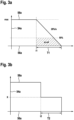
- the Figures 3a and 3b each show an example of the motor torque of the electric motor 12a.
- An ordinate axis 54a is designed as a magnitude axis and shows a degree of steering assistance in %.
- An abscissa axis 56a is designed as a time axis.
- a curve 58a shows the motor torque of the electric motor 12a.
- a malfunction and/or failure of the main control unit 10a occurs.
- the auxiliary control unit 14a is then provided to operate the electric motor 12a in such a way that the motor torque of the electric motor 12a ramps down so that the steering assistance is continuously reduced.
- a time period T1 which characterizes the ramping down of the motor torque of the electric motor 12a, is between 0.5 s and 5 s.
- a highlighted area characterizes an area of sudden loss of steering assistance (sLoA).
- Figure 3b shows an alternative to Figure 3a .
- a fault and/or failure of the main control unit 10a occurs at a time t2.
- the auxiliary control unit 14a is then provided to operate the electric motor 12a in such a way that a step-like reduction in the motor torque of the electric motor 12a is achieved, so that the steering assistance is reduced step-like.
- the auxiliary control unit 14a is provided to reduce the motor torque of the electric motor 12a and thus the steering assistance to a value x over a further period of time T2 from the time t2.
- the further time period T2 which particularly characterizes a reduction of the motor torque of the electric motor 12a to a vanishing motor torque, is between 3 s and 5 s.
- the value x is between 15 % and 30 % of a maximum motor torque.
- Figure 4 shows a further embodiment of the invention with a further steering device in a more detailed representation.
- the embodiment of the Figure 4 is followed by the letter b.
- the steering device comprises a main control unit 10b, an auxiliary control unit 14b, an electric motor 12b, a power electronics unit 16b, a first sensor unit 38b, a second sensor unit 42b and a control unit 20b, in the present case in particular in the form of separate driver electronics for the power electronics unit 16b.
- main control unit 10b has an additional connection to a vehicle bus system 70b.
- the steering device in this case comprises a switching unit 18b.
- the switching unit 18b has an electrical connection to the auxiliary control unit 14b.
- the switching unit 18b has an electrical connection with the power electronics 16b and the electric motor 12b.
- the switching unit 18b is arranged between the power electronics 16b and the electric motor 12b.
- the switching unit 18b is intended to selectively separate the individual phases of the electric motor 12b.
- the switching unit 18b comprises several switching elements (not shown), whereby in the present case exactly one of the switching elements is assigned to each phase of the electric motor 12b.
- the auxiliary control unit 14b in particular in addition to or as an alternative to controlling the power electronics 16b, is provided to control the switching unit 18b in the fault operating state and thereby operate the electric motor 12b in such a way that at least a ramping out of a motor torque, in particular an assist torque, of the electric motor 12b is achieved.
- a power supply circuit 60b of the steering device is shown.
- the main control unit 10b and the power electronics 16b have a direct connection to a power source 62b, for example in the form of a vehicle electrical system, and the auxiliary control unit 14b has an indirect connection to the same power source 62b.
- the power supply circuit 60b can, for example, comprise at least one connection switch 64b, at least one voltage regulator 66b and/or at least one capacitor 68.
- FIG. 5 A further embodiment of the invention is shown.
- the embodiment of the Figure 5 is followed by the letter c.
- the further embodiment of the Figure 5 differs from the previous embodiments at least essentially by a connection of an auxiliary control unit 14c of a steering device to a power electronics 16c of the steering device.
- the auxiliary control unit 14c is indirectly connected to the power electronics 16c at least for controlling operation of an electric motor 12c in a fault operating state.
- the steering device comprises a further control unit 72c, which is arranged between the auxiliary control unit 14c and the power electronics 16c.
- the further control unit 72c can be designed, for example, as a switching unit, as a level converter, as a line damper, as a line amplifier and/or as separate driver electronics for the power electronics 16c.
- the further control unit 72c is provided to enable and/or optimize the operation of the electric motor 12c of the steering device by the auxiliary control unit 14c in the fault operating state as a function of a further control signal 74c of the auxiliary control unit 14c, whereby a particularly high level of operational reliability can be achieved in the event of a malfunction and/or failure of a main control unit 10c.
- the further control unit 72c can advantageously interact with a control unit 20c as a changeover switch, in particular arranged between the main control unit 10c and the power electronics 16c.
- the control unit 20c and the further control unit 72c serve to alternately control the power electronics 16c by the main control unit 10c and the auxiliary control unit 14c.
- auxiliary control unit 14c is in this case provided to detect a current in the power electronics 16c by means of a connecting line 76c, whereby an at least temporary control of a motor torque of the electric motor 12c can be achieved.
- FIG. 6 A further embodiment of the invention is shown.
- the embodiment of the Figure 6 is followed by the letter d.
- the further embodiment of the Figure 6 differs from the previous embodiments at least essentially by a design of an auxiliary control unit 14d of a steering device.
- a computing power of the auxiliary control unit 14d is identical or almost identical to a computing power of a main control unit 10d.
- the auxiliary control unit 14d is intended to replace the main control unit 10d in a fault operating state and to take over control of an operation of an electric motor 12d.
- the auxiliary control unit 14d is intended to control a power electronics 16d in the fault operating state. and thereby operate the electric motor 12d in such a way that a motor torque, in particular an assist torque, of the electric motor 12d equivalent to a normal operating state can be generated.
- the auxiliary control unit 14d is therefore provided to operate the electric motor 12d in the fault operating state in a manner equivalent to the main control unit 10d, namely in such a way that a full assist torque can be provided.
- the auxiliary control unit 14d has an electrical connection with a first sensor unit 38d for detecting steering angle information, in particular a torque signal, from a steering handle.
- Figure 7 shows a further embodiment of the invention.
- the embodiment of the Figure 7 is followed by the letter e.
- an auxiliary control unit 14e is also provided to control a power electronics unit 16e in a fault operating state and thereby operate an electric motor 12e in such a way that a motor torque, in particular a support torque, of the electric motor 12e equivalent to a normal operating state can be generated.
- the auxiliary control unit 14e is provided to directly control the power electronics unit 16e.
- Driver electronics (not shown) for the power electronics unit 16e are integrated into the auxiliary control unit 14e. This advantageously means that driver electronics for the power electronics unit 16e can also be covered as a fault path with a single-chip solution.
- a main control unit 10e is provided for controlling a control unit 20e, whereby a flexibility of the steering device and/or a control of a control signal of the main control unit 10e can be further improved.
Landscapes
- Engineering & Computer Science (AREA)
- Chemical & Material Sciences (AREA)
- Combustion & Propulsion (AREA)
- Transportation (AREA)
- Mechanical Engineering (AREA)
- Power Steering Mechanism (AREA)
- Steering Control In Accordance With Driving Conditions (AREA)
Description
- Die Erfindung geht aus von einer Lenkvorrichtung nach dem Oberbegriff des Anspruch 1. Zudem betrifft die Erfindung ein Lenksystem gemäß Anspruch 11.
- Aus dem Stand der Technik sind Lenksysteme mit einer elektrischen Lenkunterstützung in Form einer Servolenkung bekannt, wobei zur Erzeugung der Lenkunterstützung ein Elektromotor eingesetzt wird. Als Sicherheitskonzept, beispielsweise bei einem Fehler einer elektrischen und/oder elektronischen Komponente des Lenksystems, dient in der Regel eine mechanische Rückfallebene, welche dazu vorgesehen ist, ein Lenken auch mit ausgefallener Lenkunterstützung zu ermöglichen und ein beherrschbaren und sicheren Betrieb zu gewährleisten. Realisiert wird der Wechsel in einen rein mechanischen Betrieb durch Abschalten einer Haupt-Steuereinheit mit einer Highlevel-Software zur Steuerung eines Betriebs des Elektromotors und/oder durch Deaktivieren einer mit dem Elektromotor verbundenen Leistungselektronik. Ein plötzliches Abschalten der Lenkunterstützung führt jedoch zu einem hohen Momentensprung an einer Lenkhandhabe des Lenksystems, was für einen Fahrer sehr irritierend sein kann und eine Unfallgefahr erhöht.
- Aus diesem Grund wird beispielsweise in der
DE 10 2010 050 820 A1 vorgeschlagen, einen Betrieb des Elektromotors bei einem Fehler der Haupt-Steuereinheit mittels einer Hilfs-Steuereinheit in Form eines Überwachungsrechners zu steuern. Die Hilfs-Steuereinheit dient in diesem Fall einerseits zur Überwachung der Haupt-Steuereinheit in einem Normalbetriebszustand und andererseits zur Ansteuerung eines Elektromotors bzw. einer Leistungselektronik in einem Fehlerbetriebszustand. - Ferner offenbart die
DE 10 2008 048 952 A1 ein Lenksystem mit einer Haupt-Steuereinheit zur Ansteuerung einer Leistungselektronik und mit einer zusätzlichen Hilfs-Steuereinheit, welche bei einem Normalbetrieb zur Überwachung und/oder zur Aufbereitung von Sensordaten für die Haupt-Steuereinheit dient und bei einem Fehler der Haupt-Steuereinheit die Leistungselektronik für einen Notlauf ansteuert, um ein hartes Abschalten und hierdurch eine Irritation des Fahrers zu verhindern.US 2017/277607 offenbart eine Lenkvorrichtung mit zumindest einer Haupt-Steuereinheit, welche in zumindest einem Normalbetriebszustand zur Steuerung eines Betriebs wenigstens eines Elektromotors vorgesehen ist, und mit zumindest einer unabhängig von der Haupt-Steuereinheit betreibbaren Hilfs-Steuereinheit, welche zur Steuerung des Betriebs des Elektromotors vorgesehen ist, wobei sich die Hilfs-Steuereinheit in dem Normalbetriebszustand in einem passiven Betriebsmodus in Form eines Ruhebetriebsmodus und/oder eines Bereitschaftsbetriebsmodus befindet, in welchem die Hilfs-Steuereinheit unbetrieben und/oder inaktiv ist. - Die Doppelfunktion der Hilfs-Steuereinheit führt jedoch in beiden Fällen zu einem stark erhöhten Rechenaufwand und schränkt gleichzeitig eine Flexibilität sowie eine Betriebssicherheit ein.
- Die Aufgabe der Erfindung besteht somit insbesondere darin, eine besonders effiziente Lenkvorrichtung mit verbesserten Eigenschaften hinsichtlich einer Flexibilität bereitzustellen. Die Aufgabe wird durch die kennzeichnenden Merkmale des Anspruchs 1 sowie die Merkmale des Anspruchs 11 gelöst, während vorteilhafte Ausgestaltungen und Weiterbildungen der Erfindung den Unteransprüchen entnommen werden können.
- Die Erfindung geht aus von einer Lenkvorrichtung, insbesondere zur Bereitstellung einer elektrischen Lenkunterstützung, mit zumindest einer Haupt-Steuereinheit, welche in zumindest einem Normalbetriebszustand zur Steuerung eines Betriebs wenigstens eines Elektromotors vorgesehen ist, und mit zumindest einer Hilfs-Steuereinheit, welche in zumindest einem, insbesondere von dem Normalbetriebszustand verschiedenen, Fehlerbetriebszustand, bei welchem eine Störung und/oder ein Ausfall der Haupt-Steuereinheit auftritt, insbesondere zumindest temporär, zur Steuerung des Betriebs des Elektromotors vorgesehen ist. Es wird vorgeschlagen, dass die Haupt-Steuereinheit, insbesondere in dem Normalbetriebszustand, unabhängig von der Hilfs-Steuereinheit betreibbar ist und sich die Hilfs-Steuereinheit in dem Normalbetriebszustand in einem passiven Betriebsmodus befindet. Durch diese Ausgestaltung kann insbesondere eine Flexibilität der Lenkvorrichtung erhöht werden. Darüber hinaus kann insbesondere ein Rechenaufwand minimiert und/oder ein Steueralgorithmus vereinfacht werden. Ferner kann vorteilhaft eine Betriebssicherheit erhöht werden, da eine Irritation eines Fahrers in dem Fehlerbetriebszustand verhindert werden kann. Zudem kann vorteilhaft eine Effizienz, insbesondere eine Leistungseffizienz, eine Steuerungseffizienz, eine Energieeffizienz, eine Bauraumeffizienz und/oder eine Kosteneffizienz, optimiert werden.
- Unter einer "Lenkvorrichtung" soll in diesem Zusammenhang insbesondere zumindest ein Teil, insbesondere eine Unterbaugruppe, eines Lenksystems, insbesondere eines Fahrzeugs und vorzugsweise eines Kraftfahrzeugs, verstanden werden. Das Lenksystem ist dabei vorteilhaft als konventionelles Lenksystem, insbesondere mit einem mechanischen Durchgriff, ausgebildet und somit insbesondere von einem als Steer-by-Wire-Lenksystem ausgebildeten Lenksystem verschieden. Zudem kann die Lenkvorrichtung insbesondere auch den Elektromotor umfassen. Darüber hinaus kann die Lenkvorrichtung weitere Bauteile und/oder Baugruppen umfassen, wie beispielsweise wenigstens eine Lenkhandhabe, wenigstens eine, vorzugsweise als Wechselrichtereinheit und/oder Endstufe ausgebildete, Leistungselektronik zum Betrieb, insbesondere zur Ansteuerung und/oder Versorgung, des Elektromotors und/oder wenigstens eine Sensoreinheit zur Erfassung einer Rotorlage des Elektromotors und/oder zur Erfassung einer Lenkwinkelinformation von der Lenkhandhabe. Der Elektromotor ist ferner insbesondere als Servomotor, vorteilhaft als bürstenloser Motor und besonders vorteilhaft als Asynchronmotor oder als permanenterregter Synchronmotor ausgebildet. Bevorzugt ist der Elektromotor dabei Teil einer elektrischen Hilfskraftlenkung und insbesondere zur Erzeugung der elektrischen Lenkunterstützung vorgesehen. Der Elektromotor könnte dabei beispielsweise als sechsphasiger, neunphasiger oder als zwölfphasiger Elektromotor ausgebildet sein. Bevorzugt wird jedoch vorgeschlagen, dass der Elektromotor als dreiphasiger Elektromotor und/oder Standard-Elektromotor ausgebildet ist. Unter "vorgesehen" soll insbesondere speziell programmiert, ausgelegt und/oder ausgestattet verstanden werden. Darunter, dass ein Objekt zu einer bestimmten Funktion vorgesehen ist, soll insbesondere verstanden werden, dass das Objekt diese bestimmte Funktion in zumindest einem Anwendungs- und/oder Betriebszustand erfüllt und/oder ausführt.
- Ferner soll unter einer "Steuereinheit" insbesondere eine elektronische Einheit verstanden werden, welche einen Informationseingang, eine Informationsverarbeitung und eine Informationsausgabe aufweist. Vorteilhaft weist die Steuereinheit, insbesondere die Haupt-Steuereinheit und/oder die Hilfs-Steuereinheit, ferner zumindest eine Recheneinheit und/oder einen Prozessor, beispielsweise in Form eines Mikroprozessors, zumindest einen Betriebsspeicher, zumindest ein Ein- und/oder Ausgabemittel, zumindest ein Betriebsprogramm, zumindest eine Steuerroutine, zumindest eine Regelroutine, zumindest eine Berechnungsroutine und/oder zumindest eine Verarbeitungsroutine auf. Die Haupt-Steuereinheit umfasst insbesondere eine Highlevel-Software zur Steuerung des Betriebs des Elektromotors. Vorteilhaft ist die Haupt-Steuereinheit dazu vorgesehen, in dem Normalbetriebszustand, insbesondere durch Ansteuerung der Leistungselektronik, ein Motormoment des Elektromotors und bevorzugt ein Unterstützungsmoment des Elektromotors einzustellen. Die Hilfs-Steuereinheit weist insbesondere eine Wirkverbindung mit der Haupt-Steuereinheit auf und ist insbesondere dazu vorgesehen, die Haupt-Steuereinheit in dem Fehlerbetriebszustand zu ersetzen und eine Steuerung des Betriebs des Elektromotors zu übernehmen. Vorteilhaft sind die Haupt-Steuereinheit in dem Normalbetriebszustand und die Hilfs-Steuereinheit in dem Fehlerbetriebszustand dazu vorgesehen, zur Steuerung des Betriebs des Elektromotors zumindest teilweise dieselben und/oder die identischen, insbesondere bestehenden, Baugruppen und Verbindungsleitungen zu verwenden und vorzugsweise dieselben Phasen des Elektromotors zu betreiben. Ferner ist die Hilfs-Steuereinheit vorzugsweise unabhängig von der Haupt-Steuereinheit betreibbar. Insbesondere ist die Hilfs-Steuereinheit zumindest und vorteilhaft ausschließlich dazu vorgesehen, in dem Fehlerbetriebszustand, insbesondere durch Ansteuerung der Leistungselektronik, ein Motormoment des Elektromotors und bevorzugt ein Unterstützungsmoment des Elektromotors zu verändern und/oder zu variieren. Bei Verwendung eines dreiphasigen Elektromotors kann durch die Steuerung des Elektromotors mittels der Haupt-Steuereinheit und der Hilfs-Steuereinheit dabei insbesondere eine Redundanz und vorteilhaft ein virtueller 6-Phasen-Betrieb bzw. 2x3-Phasen-Betrieb erreicht werden. Zudem ist die Hilfs-Steuereinheit bevorzugt zumindest zur Einleitung und/oder Bereitstellung eines Notlaufs und/oder Notbetriebs vorgesehen. Des Weiteren ist die Haupt-Steuereinheit und/oder die Hilfs-Steuereinheit vorteilhaft in ein Steuergerät der Lenkvorrichtung integriert.
- Darüber hinaus soll unter "einer Störung und/oder einem Ausfall der Haupt-Steuereinheit" insbesondere eine Störung und/oder ein Ausfall der Haupt-Steuereinheit selbst und/oder einer mit der Haupt-Steuereinheit zusammenwirkenden Peripherie-Baugruppe, wie beispielsweise einer Energieversorgung, und eine hierdurch bewirkte Störung der Haupt-Steuereinheit verstanden werden. Ferner soll unter der Wendung, dass "die Haupt-Steuereinheit unabhängig von der Hilfs-Steuereinheit betreibbar ist" insbesondere verstanden werden, dass die Steuerung des Betriebs des Elektromotors in dem Normalbetriebszustand durch die Haupt-Steuereinheit und insbesondere unabhängig von der Hilfs-Steuereinheit erfolgt. In diesem Fall ist die Haupt-Steuereinheit insbesondere eigensicher ausgebildet und insbesondere nicht zur Überwachung der Hilfs-Steuereinheit vorgesehen. Analog soll unter der Wendung, dass ""die Hilfs-Steuereinheit unabhängig von der Haupt-Steuereinheit betreibbar ist" insbesondere verstanden werden, dass die Steuerung des Betriebs des Elektromotors in dem Fehlerbetriebszustand durch die Hilfs-Steuereinheit und insbesondere unabhängig von der Haupt-Steuereinheit erfolgt. In diesem Fall ist die Hilfs-Steuereinheit insbesondere eigensicher ausgebildet und insbesondere nicht zur Überwachung der Haupt-Steuereinheit vorgesehen. Unter einem "passiven Betriebsmodus" soll ferner insbesondere ein, insbesondere energiesparender, Ruhebetriebsmodus und/oder ein, insbesondere energiesparender, Bereitschaftsbetriebsmodus verstanden werden, in welchem die Hilfs-Steuereinheit insbesondere unbetrieben und/oder inaktiv ist und insbesondere keine aktive Funktion wahrnimmt.
- Ferner wird vorgeschlagen, dass die Haupt-Steuereinheit dazu vorgesehen ist, in dem Normalbetriebszustand ein Betriebssignal, insbesondere einen Betriebsstatus, bereitzustellen und insbesondere an die Hilfs-Steuereinheit, insbesondere drahtlos, wie beispielsweise optisch und/oder induktiv, und/oder kabelgebunden, zu übermitteln. Die Hilfs-Steuereinheit ist insbesondere dazu vorgesehen, das Betriebssignal zu erfassen und/oder auszuwerten. Zudem ist die Hilfs-Steuereinheit insbesondere dazu vorgesehen, in Abhängigkeit von einem Ausbleiben des Betriebssignals die Störung und/oder den Ausfall der Haupt-Steuereinheit zu ermitteln und insbesondere einen mit dem Fehlerbetriebszustand verknüpften Fehlerbetriebsmodus zu initiieren, in welchem die Hilfs-Steuereinheit zur Steuerung des Betriebs des Elektromotors vorgesehen ist. Vorzugsweise ist die Haupt-Steuereinheit dazu elektrisch mit der Hilfs-Steuereinheit verbunden. Hierdurch kann vorteilhaft einfach ein Fehlerbetriebszustand erfasst werden, insbesondere auch in einem Betriebszustand, in welchem sich die Hilfs-Steuereinheit in einem passiven Betriebsmodus befindet. Zudem kann vorteilhaft auf eine rechenintensive Überwachung der Haupt-Steuereinheit mittels der Hilfs-Steuereinheit verzichtet werden.
- Das Betriebssignal könnte beispielsweise ein kontinuierliches Signal sein. Eine besonders hohe Energieeffizienz kann jedoch insbesondere erreicht werden, wenn das Betriebssignal ein diskontinuierliches Signal ist und die Haupt-Steuereinheit dazu vorgesehen ist, das Betriebssignal in regelmäßigen zeitlichen Abständen bereitzustellen.
- Bevorzugt ist die die Haupt-Steuereinheit dazu vorgesehen, das Betriebssignal in zeitlichen Abständen von zumindest 1 ms und vorteilhaft von zumindest 5 ms und/oder von höchstens 100 ms und vorteilhaft von höchstens 50 ms, bereitzustellen und an die Hilfs-Steuereinheit zu übermitteln. Hierdurch kann insbesondere eine Betriebssicherheit erhöht, eine sichere Erfassung des Fehlerbetriebszustand gewährleistet und gleichzeitig eine vorteilhafte Energieeffizienz erreicht werden.
- Ist eine Rechenleistung der Hilfs-Steuereinheit geringer als eine Rechenleistung der Haupt-Steuereinheit, können insbesondere Zusatzkosten für die Hilfs-Steuereinheit reduziert werden. Bevorzugt ist die Rechenleistung der Hilfs-Steuereinheit dabei um zumindest 10 %, vorteilhaft um zumindest 25 %, vorzugsweise um zumindest 50 % und besonders bevorzugt um zumindest 75 % geringer als die Rechenleistung der Haupt-Steuereinheit.
- Die Hilfs-Steuereinheit kann insbesondere dazu vorgesehen sein, den Elektromotor in dem Fehlerbetriebszustand derart zu betreiben, insbesondere zu blockieren und/oder zu bremsen, dass eine stufenförmige Verringerung eines Motormoments, insbesondere eines Unterstützungsmoments, des Elektromotors erreicht und insbesondere die Lenkunterstützung stufenförmig reduziert wird. Gemäß einer bevorzugten Ausgestaltung der Erfindung wird jedoch vorgeschlagen, dass die Hilfs-Steuereinheit dazu vorgesehen ist, den Elektromotor in dem Fehlerbetriebszustand derart zu betreiben, insbesondere zu blockieren und/oder zu bremsen, dass zumindest ein Ausrampen eines Motormoments, insbesondere eines Unterstützungsmoments, des Elektromotors erreicht wird. Vorzugsweise ist die Hilfs-Steuereinheit dabei dazu vorgesehen, den Elektromotor in dem Fehlerbetriebszustand derart zu betreiben, dass das Motormoment, insbesondere das Unterstützungsmoment, des Elektromotors kontinuierlich und insbesondere nicht schlagartig reduziert wird. Bevorzugt wird somit die bereitgestellte Lenkunterstützung kontinuierlich reduziert, wodurch insbesondere ein vorteilhaft sanfter und/oder unauffälliger Wechsel in einen rein mechanischen Betrieb erreicht und eine Irritation des Fahrers verhindert werden kann.
- In einer weiteren Ausgestaltung der Erfindung wird vorgeschlagen, dass die Hilfs-Steuereinheit dazu vorgesehen ist, den Elektromotor in dem Fehlerbetriebszustand derart zu betreiben, dass ein zu dem Normalbetriebszustand äquivalentes Motormoment, insbesondere Unterstützungsmoment, des Elektromotors erzeugbar ist. Vorzugsweise ist die Hilfs-Steuereinheit dabei dazu vorgesehen, den Elektromotor in dem Fehlerbetriebszustand auf eine zu der Haupt-Steuereinheit äquivalente Weise zu betreiben, vorteilhaft derart, dass ein volles Motormoment, insbesondere Unterstützungsmoment, bereitgestellt werden kann. Vorteilhaft ist die Hilfs-Steuereinheit ferner dazu vorgesehen, in dem Fehlerbetriebszustand, insbesondere durch Ansteuerung der Leistungselektronik, das Motormoment des Elektromotors und bevorzugt das Unterstützungsmoment des Elektromotors einzustellen. Dazu kann die Hilfs-Steuereinheit insbesondere eine Highlevel-Software zur Steuerung des Betriebs des Elektromotors umfassen. Hierdurch kann vorteilhaft eine Irritation des Fahrers weiter reduziert werden, da auch in einem Fehlerbetriebszustand eine Lenkunterstützung bereitgestellt werden kann, welche dem Fahrer ein komfortables Lenken ermöglicht. Zudem kann vorteilhaft eine Betriebssicherheit erhöht werden, da sowohl ein der Haupt-Steuereinheit zugeordneter Steuerpfad als auch ein der Hilfs-Steuereinheit zugeordneter weiterer Steuerpfad unabhängig voneinander und gleichzeitig ausreichend sicher für den Betrieb des Elektromotors sind.
- Ferner wird vorgeschlagen, dass die Lenkvorrichtung wenigstens eine Leistungselektronik, insbesondere die bereits zuvor genannte Leistungselektronik, zum Betrieb des Elektromotors umfasst, wobei die Hilfs-Steuereinheit dazu vorgesehen ist, in dem Fehlerbetriebszustand die Leistungselektronik, insbesondere mittelbar, wie beispielsweise über eine separate Treiberelektronik, oder vorteilhaft unmittelbar, anzusteuern. Hierdurch kann insbesondere eine vorteilhaft hohe Betriebssicherheit erreicht und/oder ein vorteilhaft einfacher Steueralgorithmus bereitgestellt werden.
- Alternativ oder zusätzlich wird vorgeschlagen, dass die Lenkvorrichtung wenigstens eine Schalteinheit zur Auftrennung wenigstens einer Phase des Elektromotors und vorteilhaft zur selektiven Auftrennung der einzelnen Phasen des Elektromotors umfasst, wobei die Hilfs-Steuereinheit dazu vorgesehen ist, in dem Fehlerbetriebszustand die Schalteinheit, insbesondere mittelbar oder vorteilhaft unmittelbar, anzusteuern. Vorteilhaft umfasst die Schalteinheit dabei mehrere Schaltelemente, wobei bevorzugt eine Anzahl an Schaltelementen an eine Anzahl an Phasen angepasst ist, insbesondere derart, dass jeder Phase des Elektromotors genau eines der Schaltelemente zugeordnet ist. Ferner ist die Schalteinheit vorteilhaft schaltungstechnisch zwischen der Leistungselektronik und dem Elektromotor angeordnet. Hierdurch kann vorteilhaft eine Rechenleistung der Hilfs-Steuereinheit weiter reduziert werden, wodurch vorteilhaft eine Hilfs-Steuereinheit mit einem minimalen Chipsatz für minimale Mehrkosten bereitgestellt werden kann.
- Darüber hinaus wird vorgeschlagen, dass die Lenkvorrichtung wenigstens eine Kontrolleinheit, beispielsweise eine weitere Schalteinheit, ein Pegelumsetzer, ein Leitungsdämpfer, ein Leitungsverstärker und/oder eine separate Treiberelektronik für die Leistungselektronik, umfasst, welche zumindest dazu vorgesehen ist, in dem Fehlerbetriebszustand in Abhängigkeit von einem Ansteuersignal der Hilfs-Steuereinheit einen Betrieb des Elektromotors durch die Haupt-Steuereinheit zu verhindern. Hierdurch kann insbesondere eine Betriebssicherheit erhöht werden, da die Haupt-Steuereinheit bei einem Fehler vorteilhaft von den restlichen Baugruppen abgetrennt werden kann.
- Die Lenkvorrichtung soll hierbei nicht auf die oben beschriebene Anwendung und Ausführungsform beschränkt sein. Insbesondere kann die Lenkvorrichtung zu einer Erfüllung einer hierin beschriebenen Funktionsweise eine von einer hierin genannten Anzahl von einzelnen Elementen, Bauteilen und Einheiten abweichende Anzahl aufweisen.
- Weitere Vorteile ergeben sich aus der folgenden Zeichnungsbeschreibung. In den Zeichnungen sind Ausführungsbeispiele der Erfindung dargestellt. Die Zeichnungen, die Beschreibung und die Ansprüche enthalten zahlreiche Merkmale in Kombination. Der Fachmann wird die Merkmale zweckmäßigerweise auch einzeln betrachten und zu sinnvollen weiteren Kombinationen zusammenfassen.
- Es zeigen:
- Fig. 1
- ein beispielhaftes Lenksystem mit einer Lenkvorrichtung in einer vereinfachten Darstellung,
- Fig. 2
- eine schematische Darstellung einer Ansteuerung eines Elektromotors der Lenkvorrichtung,
- Fig. 3a-b
- ein beispielhaftes Schaubild eines Ausrampens eines Motormoments des Elektromotors in einem Fehlerbetriebszustand und
- Fig. 4 - 7
- weitere Ausführungsbeispiele von Lenkvorrichtungen zur Bereitstellung einer elektrischen Lenkunterstützung.
-
Figur 1 zeigt ein beispielhaftes Lenksystem 22a in einer vereinfachten Darstellung. Das Lenksystem 22a ist als konventionelles Lenksystem mit einem mechanischen Durchgriff ausgebildet. Das Lenksystem 22a ist zudem als elektrisch unterstütztes Lenksystem ausgebildet und weist demnach eine elektrische Hilfskraftunterstützung auf. Ferner ist das Lenksystem 22a zu einem Einsatz in einem Fahrzeug (nicht dargestellt), insbesondere einem Kraftfahrzeug, vorgesehen. - Das Lenksystem 22a weist in einem eingebauten Zustand eine Wirkverbindung mit Fahrzeugrädern 24a des Fahrzeugs auf und ist zur Beeinflussung einer Fahrtrichtung des Fahrzeugs vorgesehen.
- Das Lenksystem 22a umfasst eine Lenkvorrichtung. Die Lenkvorrichtung umfasst eine, im vorliegenden Fall beispielhaft als Lenkrad ausgebildete, Lenkhandhabe 26a, welche zum Aufbringen eines manuellen Lenkmoments vorgesehen ist. Die Lenkhandhabe 26a dient folglich zum Einbringen einer Lenkvorgabe und insbesondere zur manuellen Steuerung der Fahrtrichtung des Fahrzeugs, insbesondere durch einen Fahrer.
- Darüber hinaus weist die Lenkvorrichtung ein Lenkgetriebe 28a auf, welches im vorliegenden Fall als an sich bekanntes Zahnstangenlenkgetriebe ausgebildet ist. Das Lenkgetriebe 28a umfasst ein Lenkritzel 30a und eine mit dem Lenkritzel 30a mechanisch gekoppelte Zahnstange 32a. Das Lenkgetriebe 28a ist dazu vorgesehen, eine Schwenkbewegung und/oder Drehbewegung der Fahrzeugräder 24a zu bewirken und insbesondere eine Lenkvorgabe in eine Lenkbewegung der Fahrzeugräder 24a umzusetzen.
- Zur mechanischen Verbindung der Lenkhandhabe 26a mit dem Lenkgetriebe 28a umfasst die Lenkvorrichtung ferner eine Lenksäule 34a. Die Lenksäule 34a umfasst zumindest ein Torsionselement (nicht dargestellt), im vorliegenden Fall insbesondere einen Drehstab, welches zu einer Verdrehung in Abhängigkeit von der Lenkvorgabe vorgesehen ist.
- Des Weiteren umfasst die Lenkvorrichtung eine elektrisch ausgebildete Unterstützungseinheit 36a zur Erzeugung und/oder Bereitstellung einer Lenkunterstützung. Die Unterstützungseinheit 36a ist dazu vorgesehen, ein Unterstützungsmoment in das Lenkgetriebe 28a einzubringen und das, insbesondere von dem Fahrer aufgebrachte, manuelle Lenkmoment zu unterstützen.
- Dazu umfasst die Unterstützungseinheit 36a einen, im vorliegenden Fall insbesondere als permanenterregten Synchronmotor ausgebildeten, Elektromotor 12a. Der Elektromotor 12a ist als mehrphasiger, im vorliegenden Fall dreiphasiger, Elektromotor ausgebildet. Der Elektromotor 12a steht in Wirkverbindung mit dem Lenkgetriebe 28a, insbesondere der Zahnstange 32a. Der Elektromotor 12a ist zur Erzeugung eines Motormoments, insbesondere eines Unterstützungsmoments, vorgesehen. Der Elektromotor 12a ist dabei Teil der elektrischen Hilfskraftlenkung und dient insbesondere zur Erzeugung der elektrischen Lenkunterstützung. Prinzipiell könnte ein Elektromotor jedoch auch als sechsphasiger oder als zwölfphasiger Elektromotor ausgebildet sein.
- Ferner weist die Lenkvorrichtung eine erste Sensoreinheit 38a auf. Die erste Sensoreinheit 38a umfasst zumindest einen, beispielsweise als Drehmomentsensor ausgebildeten, Winkelsensor 40a und ist zur Erfassung einer Lenkwinkelinformation 41a von der Lenkhandhabe 26a vorgesehen. Im vorliegenden Fall ist die erste Sensoreinheit 38 in einem Bereich des Torsionselements angeordnet und zu einer Erfassung einer, insbesondere mit dem Torsionselement korrelierten, Lenkwinkelinformation 41a in Form eines Drehmomentsignals vorgesehen. Das Drehmomentsignal ist dabei ein Maß für das, insbesondere von dem Fahrer aufgebrachte, manuelle Lenkmoment. Vorteilhaft kann die erste Sensoreinheit 38a jedoch auch zumindest zwei Winkelsensoren aufweisen, wodurch insbesondere eine vorteilhafte Redundanz erreicht werden kann.
- Des Weiteren weist die Lenkvorrichtung eine zweite Sensoreinheit 42a auf. Die zweite Sensoreinheit 42a umfasst zumindest einen Rotorlagesensor 44a, 46a und im vorliegenden Fall vorteilhaft zwei Rotorlagesensoren 44a, 46a (vgl. insbesondere
Figur 2 ). Die zweite Sensoreinheit 42a ist in einem Bereich des Elektromotors 12a angeordnet und zu einer Erfassung eines Rotorlagesignals 47a des Elektromotors 12a vorgesehen. Prinzipiell könnte eine zweite Sensoreinheit jedoch auch genau einen Rotorlagesensor oder zumindest drei Rotorlagesensoren aufweisen. - Darüber hinaus weist die Lenkvorrichtung ein Steuergerät 48a auf. Das Steuergerät 48a weist eine Wirkverbindung mit der ersten Sensoreinheit 38a, der zweiten Sensoreinheit 42a und der Unterstützungseinheit 36a auf. Das Steuergerät 48a ist zu einer Ansteuerung des Elektromotors 12a und somit insbesondere zu einer Einstellung des Motormoments, insbesondere in Abhängigkeit von der Lenkwinkelinformation 41a und des Rotorlagesignals 47a, vorgesehen.
-
Figur 2 zeigt einen vereinfachten, schematischen Aufbau des Steuergeräts 48a und insbesondere ein vereinfachtes Prinzip-Blockschaltbild zur Ansteuerung des Elektromotors 12a. - Die Lenkvorrichtung umfasst eine Haupt-Steuereinheit 10a. Die Haupt-Steuereinheit 10a ist im vorliegenden Fall in das Steuergerät 48a integriert. Prinzipiell könnte eine Haupt-Steuereinheit jedoch auch separat von einem Steuergerät ausgebildet sein. Die Haupt-Steuereinheit 10a umfasst zumindest einen Prozessor (nicht dargestellt), beispielsweise in Form eines Mikroprozessors. Zudem kann die Haupt-Steuereinheit 10a zumindest einen Betriebsspeicher (nicht dargestellt) umfassen. Ferner umfasst die Haupt-Steuereinheit 10a zumindest ein im Betriebsspeicher hinterlegtes Betriebsprogramm mit zumindest einer Berechnungsroutine, zumindest einer Steuerroutine und zumindest einer Verarbeitungsroutine. Die Haupt-Steuereinheit 10a weist ferner eine elektrische Verbindung mit der ersten Sensoreinheit 38a und der zweiten Sensoreinheit 42a, insbesondere einem ersten Rotorlagesensor 44a der Rotorlagesensoren 44a, 46a, auf.
- Darüber hinaus umfasst die Lenkvorrichtung eine an sich bekannte Leistungselektronik 16a, welche als Endstufe ausgebildet ist. Die Leistungselektronik 16a ist im vorliegenden Fall in das Steuergerät 48a integriert. Prinzipiell könnte eine Leistungselektronik jedoch auch separat von einem Steuergerät ausgebildet sein. Die Leistungselektronik 16a weist eine elektrische Verbindung mit der Haupt-Steuereinheit 10a und dem Elektromotor 12a auf. Die Leistungselektronik 16a ist zwischen der Haupt-Steuereinheit 10a und dem Elektromotor 12a angeordnet. Die Leistungselektronik 16a ist dazu vorgesehen, eine pulsierende gleichgerichtete Spannung einer Energiequelle in einen Phasenstrom umzuwandeln und über einen jeweiligen Mittelabgriff dem Elektromotor 12a, insbesondere einer jeweili-gen Phase des Elektromotors 12a, zuzuführen. Prinzipiell ist jedoch auch denkbar, auf eine Leistungselektronik zu verzichten oder eine Leistungselektronik in eine Haupt-Steuereinheit und/oder eine Hilfs-Steuereinheit zu integrieren.
- In einem Normalbetriebszustand ist die Haupt-Steuereinheit 10a zur Steuerung eines Betriebs des Elektromotors 12a vorgesehen. Dabei ist die Haupt-Steuereinheit 10a dazu vorgesehen, die Lenkwinkelinformation 41a und das Rotorlagesignal 47a zu empfangen und durch Ansteuerung der Leistungselektronik 16a das Motormoment des Elektromotors 12a einzustellen.
- Da es sich bei einem Lenksystem um eine sicherheitsrelevante Fahrzeugkomponente mit direktem Einfluss auf den Fahrer und/oder eine Fahrzeugführung handelt, wird in einem Fehlerbetriebszustand, in welchem eine Störung und/oder ein Ausfall der Haupt-Steuereinheit 10a selbst und/oder einer mit der Haupt-Steuereinheit 10a zusammenwirkenden Peripherie-Baugruppe, wie beispielsweise einer Energieversorgung, und eine hierdurch bewirkte Störung der Haupt-Steuereinheit 10a auftritt, ein entsprechendes Sicherheitskonzept benötigt. Als Sicherheitskonzept kann beispielsweise eine mechanische Rückfallebene dienen, welche zumindest die Lenkhandhabe 26a, die Lenksäule 34a und das Lenkgetriebe 28a umfasst und ein Lenken auch mit ausgefallener Lenkunterstützung ermöglicht. Ein plötzliches Abschalten der Lenkunterstützung bei einem Wechsel in den mechanischen Betrieb führt jedoch zu einem hohen Momentensprung an der Lenkhandhabe 26a, was für den Fahrer sehr irritierend sein kann und eine Unfallgefahr erhöht.
- Insbesondere um in einem derartigen Fall eine Irritation des Fahrers zu verhindern, umfasst die Lenkvorrichtung eine Hilfs-Steuereinheit 14a. Die Hilfs-Steuereinheit 14a ist im vorliegenden Fall in das Steuergerät 48a integriert. Die Hilfs-Steuereinheit 14a umfasst zumindest einen Prozessor (nicht dargestellt), beispielsweise in Form eines Mikroprozessors. Ferner umfasst die Hilfs-Steuereinheit 14a zumindest einen weiteren Betriebsspeicher (nicht dargestellt) mit einem im weiteren Betriebsspeicher hinterlegten weiteren Betriebsprogramm.
- Die Hilfs-Steuereinheit 14a ist getrennt von der Haupt-Steuereinheit 10a ausgebildet. Ferner ist die Hilfs-Steuereinheit 14a baulich verschieden von der Haupt-Steuereinheit 10a. Eine Rechenleistung der Hilfs-Steuereinheit 14a ist dabei um zumindest 50 % geringer als eine Rechenleistung der Haupt-Steuereinheit 10a. Prinzipiell könnte eine Hilfs-Steuereinheit jedoch auch separat von einem Steuergerät ausgebildet sein. Ferner könnte eine Rechenleistung einer Hilfs-Steuereinheit auch identisch oder nahezu identisch zu einer Rechenleistung einer Haupt-Steuereinheit sein.
- Die Hilfs-Steuereinheit 14a weist ferner eine elektrische Verbindung mit der Haupt-Steuereinheit 10a und mit der Leistungselektronik 16a auf. Zudem weist die Hilfs-Steuereinheit 14a eine elektrische Verbindung mit der zweiten Sensoreinheit 42a, insbesondere einem zweiten Rotorlagesensor 44a der Rotorlagesensoren 44a, 46a, auf. Die Hilfs-Steuereinheit 14a ist im vorliegenden Fall jedoch frei von einer elektrischen Verbindung mit der ersten Sensoreinheit 38a. Grundsätzlich könnte eine Hilfs-Steuereinheit jedoch auch eine elektrische Verbindung mit einer ersten Sensoreinheit aufweisen, wie beispielsweise in einigen der folgenden Ausführungsbeispielen dargestellt.
- Darüber hinaus sind die Hilfs-Steuereinheit 14a und die Haupt-Steuereinheit 10a unabhängig voneinander betreibbar. Die Hilfs-Steuereinheit 14a befindet sich in dem Normalbetriebszustand in einem rein passiven Betriebsmodus und ist ausschließlich in dem Fehlerbetriebszustand zur Steuerung des Betriebs des Elektromotors 12a vorgesehen. Im vorliegenden Fall ist die Hilfs-Steuereinheit 14a dazu vorgesehen, die Haupt-Steuereinheit 10a in dem Fehlerbetriebszustand zu ersetzen und eine Steuerung des Betriebs des Elektromotors 12a zu übernehmen, um einen Notlauf und/oder einen Notbetrieb einzuleiten. Die Hilfs-Steuereinheit 14a ist zudem dazu vorgesehen, zur Steuerung des Betriebs des Elektromotors 12a zumindest teilweise dieselben und/oder die identischen, insbesondere bestehenden, Baugruppen und Verbindungsleitungen zu verwenden und dieselben Phasen des Elektromotors 12a wie die Haupt-Steuereinheit 10a zu betreiben. Bei der Verwendung eines dreiphasigen Elektromotors 12a kann hierdurch eine Redundanz erreicht und vorteilhaft ein virtueller 6-Phasen-Betrieb bzw. 2x3-Phasen-Betrieb erreicht werden. Im vorliegenden Fall ist die Hilfs-Steuereinheit 14a dazu vorgesehen, in dem Fehlerbetriebszustand die Leistungselektronik 16a unmittelbar anzusteuern und hierdurch den Elektromotor 12a derart zu betreiben, dass ein Ausrampen des Motormoments, insbesondere des Unterstützungsmoments, des Elektromotors 12a erreicht wird und Lenkbewegungen an der Lenkhandhabe 26a vorteilhaft gedämpft werden. Insbesondere wird dabei durch die Hilfs-Steuereinheit 14a das Motormoment des Elektromotors 12a und somit die bereitgestellte Lenkunterstützung kontinuierlich und insbesondere nicht schlagartig reduziert, wodurch insbesondere ein vorteilhaft sanfter und/oder unauffälliger Wechsel in den mechanischen Betrieb erreicht und eine Irritation des Fahrers verhindert werden kann.
- Zur Ermittlung des Fehlerbetriebszustands, insbesondere der Störung und/oder des Ausfalls der Haupt-Steuereinheit 10a, ist die Haupt-Steuereinheit 10a dazu vorgesehen, in dem Normalbetriebszustand ein Betriebssignal 50a bereitzustellen und insbesondere an die Hilfs-Steuereinheit 14a zu übermitteln. Das Betriebssignal 50a ist im vorliegenden Fall ein diskontinuierliches Signal und wird in regelmäßigen zeitlichen Abständen zwischen 1 ms und 100 ms von der Haupt-Steuereinheit 10a an die Hilfs-Steuereinheit 14a übermittelt. Die, in dem Normalbetriebszustand insbesondere passive, Hilfs-Steuereinheit 14a ist dazu vorgesehen, das Betriebssignal 50a zu erfassen. Im Falle einer Störung und/oder eines Ausfalls der Haupt-Steuereinheit 10a wird das Betriebssignal 50a nicht mehr von der Haupt-Steuereinheit 10a erzeugt, sodass die Hilfs-Steuereinheit 14a anhand eines Ausbleibens des Betriebssignals 50a die Störung und/oder den Ausfall der Haupt-Steuereinheit 10a ermitteln und insbesondere einen mit dem Fehlerbetriebszustand verknüpften Fehlerbetriebsmodus initiieren kann, in welchem die Hilfs-Steuereinheit 14a die Steuerung des Betriebs des Elektromotors 12a übernimmt. Grundsätzlich könnte ein Betriebssignal jedoch auch einem kontinuierlichen Signal entsprechen.
- Darüber hinaus umfasst die Lenkvorrichtung im vorliegenden Fall eine Kontrolleinheit 20a. Die Kontrolleinheit 20a ist im vorliegenden Fall in das Steuergerät 48a integriert. Prinzipiell könnte eine Kontrolleinheit jedoch auch separat von einem Steuergerät ausgebildet sein. Die Kontrolleinheit 20a weist eine elektrische Verbindung mit der Hilfs-Steuereinheit 14a auf. Zudem weist die Kontrolleinheit 20a eine elektrische Verbindung mit der Haupt-Steuereinheit 10a und der Leistungselektronik 16a auf. Im vorliegenden Fall ist die Kontrolleinheit 20a zwischen der Haupt-Steuereinheit 10a und der Leistungselektronik 16a angeordnet. Die Kontrolleinheit 20a kann beispielsweise als Schalteinheit, als Pegelumsetzer, als Leitungsdämpfer, als Leitungsverstärker und/oder als separate Treiberelektronik für die Leistungselektronik 16a, ausgebildet sein. Die Kontrolleinheit 20a ist zumindest dazu vorgesehen, in dem Fehlerbetriebszustand in Abhängigkeit von einem Ansteuersignal 52a der Hilfs-Steuereinheit 14a einen Betrieb des Elektromotors 12a durch die Haupt-Steuereinheit 10a zu verhindern. Im vorliegenden Fall ist die Kontrolleinheit 20a dabei zumindest dazu vorgesehen, die Haupt-Steuereinheit 10a von der Leistungselektronik 16a abzukoppeln, wodurch insbesondere eine Betriebssicherheit erhöht werden kann, da die Haupt-Steuereinheit 10a bei einem Fehler von den restlichen Baugruppen abgetrennt werden kann. Prinzipiell ist jedoch auch denkbar, auf eine Kontrolleinheit vollständig zu verzichten. Ferner könnte eine Kontrolleinheit beispielsweise in Form einer Treiberelektronik für eine Leistungselektronik auch in die Leistungselektronik, eine Haupt-Steuereinheit und/oder eine Hilfs-Steuereinheit integriert sein.
- Darüber hinaus kann die Lenkvorrichtung und/oder das Steuergerät 48a weitere Bauteile und/oder Baugruppen umfassen, wie beispielsweise eine Energieversorgungsschaltung und/oder eine Schalteinheit zur Auftrennung wenigstens einer Phase des Elektromotors 12a.
- Die
Figuren 3a und 3b zeigen jeweils einen beispielhaften Verlauf des Motormoments des Elektromotors 12a. Eine Ordinatenachse 54a ist jeweils als Größenachse ausgebildet und zeigt einen Grad der Lenkunterstützung in %. Eine Abszissenachse 56a ist jeweils als Zeitachse ausgebildet. Ein Kurve 58a zeigt jeweils das Motormoment des Elektromotors 12a. - In
Figur 3a tritt zu einem Zeitpunkt t1 eine Störung und/oder ein Ausfall der Haupt-Steuereinheit 10a auf. Anschließend ist die Hilfs-Steuereinheit 14a dazu vorgesehen, den Elektromotor 12a derart zu betreiben, dass ein Ausrampen des Motormoments des Elektromotors 12a erreicht wird, sodass die Lenkunterstützung kontinuierlich reduziert wird. Eine Zeitdauer T1, welche das Ausrampen des Motormoments des Elektromotors 12a charakterisiert beträgt dabei zwischen 0,5 s und 5 s. Ein hervorgehobener Bereich charakterisiert einen Bereich eines plötzlichen Verlusts der Lenkunterstützung (sudden loss of assistance =sLoA). -
Figur 3b zeigt eine Alternative zurFigur 3a . In diesem Fall tritt zu einem Zeitpunkt t2 eine Störung und/oder ein Ausfall der Haupt-Steuereinheit 10a auf. Anschließend ist die Hilfs-Steuereinheit 14a dazu vorgesehen, den Elektromotor 12a derart zu betreiben, dass eine stufenförmige Verringerung des Motormoments des Elektromotors 12a erreicht wird, sodass die Lenkunterstützung stufenförmig reduziert wird. Im vorliegenden Fall ist die Hilfs-Steuereinheit 14a dazu vorgesehen, ab dem Zeitpunkt t2 das Motormoment des Elektromotors 12a und somit die Lenkunterstützung über eine weitere Zeitdauer T2 auf einen Wert x zu verringern. - Die weitere Zeitdauer T2, welche insbesondere eine Verringerung des Motormoments des Elektromotors 12a auf ein verschwindendes Motormoment charakterisiert, beträgt dabei zwischen 3 s und 5 s. Der Wert x liegt zwischen 15 % und 30 % eines maximalen Motormoments. Auch wenn in
Figur 3b beispielhaft lediglich eine Stufe dargestellt ist, kann eine Hilfs-Steuereinheit auch dazu vorgesehen sein, einen Elektromotor mit mehreren Stufen anzusteuern, um eine stufenförmige Verringerung eines Motormoments eines Elektromotors zu erreichen. - In den
Figuren 4 bis 7 sind weitere Ausführungsbeispiele der Erfindung gezeigt. Die nachfolgenden Beschreibungen und die Zeichnungen beschränken sich im Wesentlichen auf die Unterschiede zwischen den Ausführungsbeispielen, wobei bezüglich gleich bezeichneter Bauteile, insbesondere in Bezug auf Bauteile mit gleichen Bezugszeichen, grundsätzlich auch auf die Zeichnungen und/oder die Beschreibung der anderen Ausführungsbeispiele, insbesondere derFiguren 1 bis 3b , verwiesen werden kann. Zur Unterscheidung der Ausführungsbeispiele ist der Buchstabe a den Bezugszeichen des Ausführungsbeispiels in denFiguren 1 bis 3b nachgestellt. In den Ausführungsbeispielen derFiguren 4 bis 7 ist der Buchstabe a durch die Buchstaben b bis e ersetzt. -
Figur 4 zeigt ein weiteres Ausführungsbeispiel der Erfindung mit einer weiteren Lenkvorrichtung in einer detaillierteren Darstellung. Dem Ausführungsbeispiel derFigur 4 ist der Buchstabe b nachgestellt. - Die Lenkvorrichtung umfasst dabei analog zum vorherigen Ausführungsbeispiel eine Haupt-Steuereinheit 10b, eine Hilfs-Steuereinheit 14b, einen Elektromotor 12b, eine Leistungselektronik 16b, eine erste Sensoreinheit 38b, eine zweite Sensoreinheit 42b sowie eine Kontrolleinheit 20b, im vorliegenden Fall insbesondere in Form einer separaten Treiberelektronik für die Leistungselektronik 16b.
- Ferner weist die Haupt-Steuereinheit 10b eine zusätzliche Anbindung an ein Fahrzeugbus-System 70b auf.
- Darüber hinaus umfasst die Lenkvorrichtung in diesem Fall eine Schalteinheit 18b. Die Schalteinheit 18b weist eine elektrische Verbindung mit der Hilfs-Steuereinheit 14b auf. Zudem weist die Schalteinheit 18b eine elektrische Verbindung mit der Leistungselektronik 16b und dem Elektromotor 12b auf. Im vorliegenden Fall ist die Schalteinheit 18b zwischen der Leistungselektronik 16b und dem Elektromotor 12b angeordnet. Die Schalteinheit 18b ist dazu vorgesehen, die einzelnen Phasen des Elektromotors 12b selektiv aufzutrennen. Dazu umfasst die Schalteinheit 18b mehrere Schaltelemente (nicht dargestellt), wobei im vorliegenden Fall jeder Phase des Elektromotors 12b genau eines der Schaltelemente zugeordnet ist.
- In diesem Fall ist die Hilfs-Steuereinheit 14b, insbesondere zusätzlich oder alternativ zur Ansteuerung der Leistungselektronik 16b, dazu vorgesehen, in dem Fehlerbetriebszustand die Schalteinheit 18b anzusteuern und hierdurch den Elektromotor 12b derart zu betreiben, dass zumindest ein Ausrampen eines Motormoments, insbesondere eines Unterstützungsmoments, des Elektromotors 12b erreicht wird.
- Ferner ist in
Figur 4 zusätzlich eine Energieversorgungsschaltung 60b der Lenkvorrichtung gezeigt. In diesem Fall weisen die Haupt-Steuereinheit 10b und die Leistungselektronik 16b eine unmittelbare Verbindung mit einer Energiequelle 62b, beispielsweise in Form eines Fahrzeugbordnetzes, und die Hilfs-Steuereinheit 14b eine mittelbare Verbindung mit derselben Energiequelle 62b auf. Zur Anbindung der Hilfs-Steuereinheit 14b an die Energiequelle 62b kann die Energieversorgungsschaltung 60b beispielsweise zumindest einen Verbindungsschalter 64b, zumindest einen Spannungsregler 66b und/oder zumindest einen Kondensator 68 umfassen. - In
Figur 5 ist ein weiteres Ausführungsbeispiel der Erfindung gezeigt. Dem Ausführungsbeispiel derFigur 5 ist der Buchstabe c nachgestellt. Das weitere Ausführungsbeispiel derFigur 5 unterscheidet sich von den vorherigen Ausführungsbeispielen zumindest im Wesentlichen durch eine Anbindung einer Hilfs-Steuereinheit 14c einer Lenkvorrichtung an eine Leistungselektronik 16c der Lenkvorrichtung. - In diesem Fall ist die Hilfs-Steuereinheit 14c zumindest zur Steuerung eines Betriebs eines Elektromotors 12c in einem Fehlerbetriebszustand mittelbar mit der Leistungselektronik 16c verbunden.
- Dazu umfasst die Lenkvorrichtung eine weitere Kontrolleinheit 72c, welche zwischen der Hilfs-Steuereinheit 14c und der Leistungselektronik 16c angeordnet ist. Die weitere Kontrolleinheit 72c kann beispielsweise als Schalteinheit, als Pegelumsetzer, als Leitungsdämpfer, als Leitungsverstärker und/oder als separate Treiberelektronik für die Leistungselektronik 16c ausgebildet sein. Die weitere Kontrolleinheit 72c ist dazu vorgesehen, in dem Fehlerbetriebszustand in Abhängigkeit von einem weiteren Ansteuersignal 74c der Hilfs-Steuereinheit 14c den Betrieb des Elektromotors 12c der Lenkvorrichtung durch die Hilfs-Steuereinheit 14c zu ermöglichen und/oder zu optimieren, wodurch eine besonders hohe Betriebssicherheit bei einer Störung und/oder einem Ausfall einer Haupt-Steuereinheit 10c erreicht werden kann. Vorteilhaft kann die weitere Kontrolleinheit 72c dabei mit einer, insbesondere zwischen der Haupt-Steuereinheit 10c und der Leistungselektronik 16c angeordneten, Kontrolleinheit 20c als Wechselschalter zusammenwirken. Die Kontrolleinheit 20c und die weitere Kontrolleinheit 72c dienen in diesem Fall zum wechselseitigen Ansteuern der Leistungselektronik 16c durch die Hauptsteuereinheit 10c und die Hilfs-Steuereinheit 14c.
- Darüber hinaus ist die Hilfs-Steuereinheit 14c in diesem Fall dazu vorgesehen, mittels einer Verbindungsleitung 76c einen Strom in der Leistungselektronik 16c zu erfassen, wodurch eine zumindest temporäre Regelung eines Motormoments des Elektromotors 12c erreicht werden kann.
- In
Figur 6 ist ein weiteres Ausführungsbeispiel der Erfindung gezeigt. Dem Ausführungsbeispiel derFigur 6 ist der Buchstabe d nachgestellt. Das weitere Ausführungsbeispiel derFigur 6 unterscheidet sich von den vorherigen Ausführungsbeispielen zumindest im Wesentlichen durch eine Ausgestaltung einer Hilfs-Steuereinheit 14d einer Lenkvorrichtung. - In diesem Fall ist eine Rechenleistung der Hilfs-Steuereinheit 14d identisch oder nahezu identisch zu einer Rechenleistung einer Haupt-Steuereinheit 10d. Die Hilfs-Steuereinheit 14d ist dazu vorgesehen, die Haupt-Steuereinheit 10d in einem Fehlerbetriebszustand zu ersetzen und eine Steuerung eines Betriebs eines Elektromotors 12d zu übernehmen. Dabei ist die Hilfs-Steuereinheit 14d dazu vorgesehen, in dem Fehlerbetriebszustand eine Leistungselektronik 16d anzusteuern und hierdurch den Elektromotor 12d derart zu betreiben, dass ein zu einem Normalbetriebszustand äquivalentes Motormoment, insbesondere Unterstützungsmoment, des Elektromotors 12d erzeugbar ist. Die Hilfs-Steuereinheit 14d ist folglich dazu vorgesehen, den Elektromotor 12d in dem Fehlerbetriebszustand auf eine zu der Haupt-Steuereinheit 10d äquivalente Weise zu betreiben und zwar derart, dass ein volles Unterstützungsmoment bereitgestellt werden kann.
- Hierzu weist die Hilfs-Steuereinheit 14d eine elektrischen Verbindung mit einer ersten Sensoreinheit 38d zur Erfassung einer Lenkwinkelinformation, insbesondere eines Drehmomentsignals, von einer Lenkhandhabe auf.
-
Figur 7 zeigt ein weiteres Ausführungsbeispiel der Erfindung. Dem Ausführungsbeispiel derFigur 7 ist der Buchstabe e nachgestellt. - In diesem Fall ist eine Hilfs-Steuereinheit 14e ebenfalls dazu vorgesehen, in einem Fehlerbetriebszustand eine Leistungselektronik 16e anzusteuern und hierdurch einen Elektromotor 12e derart zu betreiben, dass ein zu einem Normalbetriebszustand äquivalentes Motormoment, insbesondere Unterstützungsmoment, des Elektromotors 12e erzeugbar ist. Allerdings ist die Hilfs-Steuereinheit 14e dabei zu einer unmittelbaren Ansteuerung der Leistungselektronik 16e vorgesehen. Dabei ist eine Treiberelektronik (nicht dargestellt) für die Leistungselektronik 16e in die Hilfs-Steuereinheit 14e integriert. Hierdurch kann vorteilhaft auch mit einer Ein-Chip-Lösung eine Treiberelektronik für die Leistungselektronik 16e als Fehlerpfad mit abgedeckt werden.
- Ferner ist in diesem Fall eine Haupt-Steuereinheit 10e zu einer Ansteuerung einer Kontrolleinheit 20e vorgesehen, wodurch eine Flexibilität der Lenkvorrichtung und/oder eine Kontrolle eines Steuersignals der Haupt-Steuereinheit 10e weiter verbessert werden kann.
Claims (11)
- Lenkvorrichtung, insbesondere zur Bereitstellung einer elektrischen Lenkunterstützung, mit zumindest einer Haupt-Steuereinheit (10a-e), welche in zumindest einem Normalbetriebszustand zur Steuerung eines Betriebs wenigstens eines Elektromotors (12a-e) vorgesehen ist, und mit zumindest einer unabhängig von der Haupt-Steuereinheit (10a-e) betreibbaren Hilfs-Steuereinheit (14a-e), welche ausschließlich in einem Fehlerbetriebszustand, bei welchem eine Störung und/oder ein Ausfall der Haupt-Steuereinheit (10a-e) auftritt, zur Steuerung des Betriebs des Elektromotors (12a-e) vorgesehen ist, wobei sich die Hilfs-Steuereinheit (14a-e) in dem Normalbetriebszustand in einem passiven Betriebsmodus in Form eines Ruhebetriebsmodus und/oder eines Bereitschaftsbetriebsmodus befindet, in welchem die Hilfs-Steuereinheit (14a-e) unbetrieben und/oder inaktiv ist.
- Lenkvorrichtung nach Anspruch 1, dadurch gekennzeichnet, dass die Haupt-Steuereinheit (10a-e) dazu vorgesehen ist, in dem Normalbetriebszustand ein Betriebssignal (50a) bereitzustellen und die Hilfs-Steuereinheit (14a-e) dazu vorgesehen ist, in Abhängigkeit von einem Ausbleiben des Betriebssignals (50a) die Störung und/oder den Ausfall der Haupt-Steuereinheit (10a-e) zu ermitteln.
- Lenkvorrichtung nach Anspruch 2, dadurch gekennzeichnet, dass das Betriebssignal (50a) ein diskontinuierliches Signal ist und die Haupt-Steuereinheit (10a-e) dazu vorgesehen ist, das Betriebssignal (50a) in regelmäßigen zeitlichen Abständen bereitzustellen.
- Lenkvorrichtung nach Anspruch 2 oder 3, dadurch gekennzeichnet, dass die Haupt-Steuereinheit (10a-e) dazu vorgesehen ist, das Betriebssignal (50a) in zeitlichen Abständen von zumindest 1 ms und/oder von höchstens 100 ms bereitzustellen.
- Lenkvorrichtung nach einem der vorhergehenden Ansprüche, dadurch gekennzeichnet, dass eine Rechenleistung der Hilfs-Steuereinheit (14a-c) geringer als eine Rechenleistung der Haupt-Steuereinheit (10a-c) ist.
- Lenkvorrichtung nach einem der vorhergehenden Ansprüche, dadurch gekennzeichnet, dass die Hilfs-Steuereinheit (14a-e) dazu vorgesehen ist, den Elektromotor (12a-e) in dem Fehlerbetriebszustand derart zu betreiben, dass zumindest ein Ausrampen eines Motormoments des Elektromotors (12a-e) erreicht wird.
- Lenkvorrichtung nach einem der vorhergehenden Ansprüche, dadurch gekennzeichnet, dass die Hilfs-Steuereinheit (14d; 14e) dazu vorgesehen ist, den Elektromotor (12d; 12e) in dem Fehlerbetriebszustand derart zu betreiben, dass ein zu dem Normalbetriebszustand äquivalentes Motormoment des Elektromotors (12d; 12e) erzeugbar ist.
- Lenkvorrichtung nach einem der vorhergehenden Ansprüche, gekennzeichnet durch wenigstens eine Leistungselektronik (16a-e) zum Betrieb des Elektromotors (12a-e), wobei die Hilfs-Steuereinheit (14a-e) dazu vorgesehen ist, in dem Fehlerbetriebszustand die Leistungselektronik (16a-e) anzusteuern.
- Lenkvorrichtung nach einem der vorhergehenden Ansprüche, gekennzeichnet durch wenigstens eine Schalteinheit (18b) zur Auftrennung wenigstens einer Phase des Elektromotors (12b-e), wobei die Hilfs-Steuereinheit (14b-e) dazu vorgesehen ist, in dem Fehlerbetriebszustand die Schalteinheit (18b-e) anzusteuern.
- Lenkvorrichtung nach einem der vorhergehenden Ansprüche, gekennzeichnet durch wenigstens eine Kontrolleinheit (20a; 20b; 20c; 20e), welche zumindest dazu vorgesehen ist, in dem Fehlerbetriebszustand in Abhängigkeit von einem Ansteuersignal (52a) der Hilfs-Steuereinheit (14a-e) einen Betrieb des Elektromotors (12a-e) durch die Haupt-Steuereinheit (10a-e) zu verhindern.
- Lenksystem (22a) mit zumindest einer Lenkvorrichtung nach einem der vorhergehenden Ansprüche.
Applications Claiming Priority (2)
| Application Number | Priority Date | Filing Date | Title |
|---|---|---|---|
| DE102017223814.3A DE102017223814A1 (de) | 2017-12-27 | 2017-12-27 | Lenkvorrichtung |
| PCT/EP2018/082831 WO2019129455A1 (de) | 2017-12-27 | 2018-11-28 | Lenkvorrichtung |
Publications (2)
| Publication Number | Publication Date |
|---|---|
| EP3732087A1 EP3732087A1 (de) | 2020-11-04 |
| EP3732087B1 true EP3732087B1 (de) | 2024-07-31 |
Family
ID=64901473
Family Applications (1)
| Application Number | Title | Priority Date | Filing Date |
|---|---|---|---|
| EP18826958.3A Active EP3732087B1 (de) | 2017-12-27 | 2018-11-28 | Lenkvorrichtung |
Country Status (7)
| Country | Link |
|---|---|
| US (1) | US11565745B2 (de) |
| EP (1) | EP3732087B1 (de) |
| JP (1) | JP7065973B2 (de) |
| KR (1) | KR102741210B1 (de) |
| CN (1) | CN111491852B (de) |
| DE (1) | DE102017223814A1 (de) |
| WO (1) | WO2019129455A1 (de) |
Families Citing this family (4)
| Publication number | Priority date | Publication date | Assignee | Title |
|---|---|---|---|---|
| DE102018114828B3 (de) * | 2018-06-20 | 2019-07-25 | Thyssenkrupp Ag | Kraftfahrzeuglenkung mit einem redundant ausgelegten Steuergerät |
| JP7318450B2 (ja) * | 2019-09-24 | 2023-08-01 | 株式会社ジェイテクト | 転舵装置 |
| JP7594842B2 (ja) | 2021-12-21 | 2024-12-05 | 三菱電機モビリティ株式会社 | モータ制御装置および電動パワーステアリング装置 |
| DE102023209792A1 (de) * | 2023-10-09 | 2025-04-10 | Robert Bosch Gesellschaft mit beschränkter Haftung | Lenksystem und Verfahren zum Betrieb eines Lenksystems |
Citations (1)
| Publication number | Priority date | Publication date | Assignee | Title |
|---|---|---|---|---|
| US20170277607A1 (en) * | 2016-03-23 | 2017-09-28 | GM Global Technology Operations LLC | Fault-tolerance pattern and switching protocol for multiple hot and cold standby redundancies |
Family Cites Families (23)
| Publication number | Priority date | Publication date | Assignee | Title |
|---|---|---|---|---|
| JPH0796388B2 (ja) * | 1987-04-13 | 1995-10-18 | 株式会社日立製作所 | 電動式パワ−ステアリング装置 |
| JP2853377B2 (ja) * | 1991-06-20 | 1999-02-03 | トヨタ自動車株式会社 | 車両の電気制御装置 |
| JP2884942B2 (ja) * | 1992-09-17 | 1999-04-19 | 株式会社日立製作所 | 電気車制御装置 |
| JPH06329042A (ja) * | 1993-05-26 | 1994-11-29 | Nippondenso Co Ltd | 後輪操舵装置 |
| JP3839142B2 (ja) * | 1997-09-19 | 2006-11-01 | 本田技研工業株式会社 | 電動機駆動装置 |
| JP3968972B2 (ja) * | 2000-08-14 | 2007-08-29 | 日本精工株式会社 | 電動パワーステアリング装置の制御装置 |
| JP4031931B2 (ja) | 2001-12-10 | 2008-01-09 | 三甲株式会社 | 合成樹脂製パレット |
| JP3824527B2 (ja) | 2001-12-10 | 2006-09-20 | 株式会社ジェイテクト | パワーステアリング装置 |
| JP2006329042A (ja) | 2005-05-25 | 2006-12-07 | Babcock Hitachi Kk | ディーゼル排ガス浄化装置および運転制御方法 |
| JP4473809B2 (ja) | 2005-11-09 | 2010-06-02 | 株式会社デンソー | 移動体案内装置 |
| US7828112B2 (en) * | 2006-05-26 | 2010-11-09 | Mitsubishi Electric Corporation | Electric power steering device |
| DE102008048952A1 (de) | 2008-09-25 | 2010-04-01 | Volkswagen Ag | Vorrichtung und Verfahren zur Steuerung einer elektrischen Lenkung |
| CN101734135A (zh) * | 2009-12-29 | 2010-06-16 | 东莞市精航达电动转向系统有限公司 | 一种车辆电动助力转向控制方法及其控制装置 |
| WO2011158876A1 (ja) * | 2010-06-18 | 2011-12-22 | 日立オートモティブシステムズ株式会社 | 電子制御装置 |
| DE102010050819A1 (de) * | 2010-11-09 | 2012-05-10 | Audi Ag | Vorrichtung zum Ansteuern eines Elektromotors für eine elektrische Hilfskraftlenkung |
| DE102010050820B4 (de) | 2010-11-09 | 2021-06-24 | Audi Ag | Vorrichtung zum Ansteuern eines Elektromotors für eine Hilfskraftlenkung |
| JP5189659B2 (ja) * | 2011-01-13 | 2013-04-24 | 三菱電機株式会社 | レゾルバの異常検出装置 |
| CN103747999B (zh) * | 2011-10-24 | 2016-03-02 | 三菱电机株式会社 | 电动助力转向装置 |
| DE102012204263A1 (de) * | 2012-03-19 | 2013-09-19 | Continental Teves Ag & Co. Ohg | Fremdkraftbremsanlage |
| JP6379907B2 (ja) * | 2014-09-16 | 2018-08-29 | 株式会社ジェイテクト | 電動パワーステアリング装置 |
| DE102014117406B4 (de) * | 2014-11-27 | 2018-04-26 | Robert Bosch Automotive Steering Gmbh | Verfahren zum betreiben eines lenksystems |
| DE102015115423B4 (de) * | 2015-09-14 | 2021-07-01 | Robert Bosch Gmbh | Verfahren und Vorrichtung zum Betreiben eines Servolenksystems eines Fahrzeugs, Servolenksystem |
| DE102015116937B4 (de) | 2015-10-06 | 2018-10-31 | Robert Bosch Automotive Steering Gmbh | Verfahren zum Betreiben eines Lenksystems eines Kraftfahrzeugs |
-
2017
- 2017-12-27 DE DE102017223814.3A patent/DE102017223814A1/de not_active Ceased
-
2018
- 2018-11-28 WO PCT/EP2018/082831 patent/WO2019129455A1/de not_active Ceased
- 2018-11-28 JP JP2020536107A patent/JP7065973B2/ja active Active
- 2018-11-28 KR KR1020207018626A patent/KR102741210B1/ko active Active
- 2018-11-28 CN CN201880083401.4A patent/CN111491852B/zh active Active
- 2018-11-28 EP EP18826958.3A patent/EP3732087B1/de active Active
- 2018-12-28 US US16/772,264 patent/US11565745B2/en active Active
Patent Citations (1)
| Publication number | Priority date | Publication date | Assignee | Title |
|---|---|---|---|---|
| US20170277607A1 (en) * | 2016-03-23 | 2017-09-28 | GM Global Technology Operations LLC | Fault-tolerance pattern and switching protocol for multiple hot and cold standby redundancies |
Also Published As
| Publication number | Publication date |
|---|---|
| EP3732087A1 (de) | 2020-11-04 |
| JP2021508635A (ja) | 2021-03-11 |
| KR102741210B1 (ko) | 2024-12-12 |
| DE102017223814A1 (de) | 2019-06-27 |
| CN111491852A (zh) | 2020-08-04 |
| CN111491852B (zh) | 2022-11-04 |
| WO2019129455A1 (de) | 2019-07-04 |
| US20210086827A1 (en) | 2021-03-25 |
| US11565745B2 (en) | 2023-01-31 |
| KR20200103692A (ko) | 2020-09-02 |
| JP7065973B2 (ja) | 2022-05-12 |
Similar Documents
| Publication | Publication Date | Title |
|---|---|---|
| EP3810486B1 (de) | Kraftfahrzeuglenkung mit einem redundant ausgelegten steuergerät | |
| DE4422031B4 (de) | Fahrzeuglenksystem | |
| DE602005005399T2 (de) | Elektrische Servolenkung | |
| EP2450259B1 (de) | Kraftfahrzeug mit elektrischer Hilfskraftlenkung | |
| EP3752407B1 (de) | Verfahren zur bereitstellung einer lenkkraftunterstützung für ein elektromechanisches lenksystem eines kraftfahrzeuges mit einem redundant ausgelegten steuergerät | |
| EP3765348A1 (de) | Elektromechanische kraftfahrzeuglenkung mit einem redundant ausgelegten steuergerät | |
| DE112015000941T5 (de) | Fahrzeugseitige Vorrichtungssteuereinheit und Lenkunterstützungsvorrichtung | |
| DE112016001949T5 (de) | Elektrische Servolenksteuervorrichtung | |
| EP4273025A1 (de) | Steer-by-wire-lenksystem und verfahren zum betreiben eines steer-by-wire-lenksystems in einem normalbetriebsmodus und in einem sonderbetriebsmodus | |
| DE102017215842B4 (de) | Verfahren zum Betrieb einer Lenkvorrichtung und Lenkvorrichtung | |
| EP2331383B1 (de) | Vorrichtung und verfahren zur steuerung einer elektrischen lenkung | |
| DE102017223814A1 (de) | Lenkvorrichtung | |
| EP2608996B1 (de) | Sicherheitsschaltung für einen elektromotor einer elektromechanischen lenkung | |
| EP1845007A1 (de) | Verfahren zum Betrieb eines elektrischen Servolenksystems | |
| EP3747733B1 (de) | Verfahren zum betreiben eines lenksystems | |
| DE112018007700T5 (de) | Lenkeinrichtung | |
| DE102019117222A1 (de) | Steer-by-Wire-Lenksystem, Verfahren zum Betrieb eines Steer-by-Wire-Lenksystems und Fahrzeug | |
| DE10035356A1 (de) | Elektrisches Servolenkgerät | |
| DE102005044629A1 (de) | Elektromotorregelung mit kontrolliertem Fehlerabfang | |
| DE102017220069B4 (de) | Verfahren zum Betrieb eines Lenksystems in einem Fahrzeug | |
| DE102020203622A1 (de) | Fahrzeug und Verfahren zur Übergabe einer Lenkfunktion an einen Fahrer eines Fahrzeugs | |
| EP1521701B1 (de) | Verfahren zum lenken eines fahrzeugs mit einer überlagerungslenkung | |
| EP3856610B1 (de) | Steer-by-wire-lenksystem für ein kraftfahrzeug und verfahren zum betreiben eines steer-by-wire-lenksystems für ein kraftfahrzeug | |
| WO2023057192A1 (de) | Steuervorrichtung und verfahren zum betreiben eines elektromotors, insbesondere eines lenksystems | |
| EP3470301B1 (de) | Lenkungssteuersystem für ein lenksystem eines kraftfahrzeuges sowie verfahren zum betreiben eines lenkungssteuersystems |
Legal Events
| Date | Code | Title | Description |
|---|---|---|---|
| STAA | Information on the status of an ep patent application or granted ep patent |
Free format text: STATUS: UNKNOWN |
|
| STAA | Information on the status of an ep patent application or granted ep patent |
Free format text: STATUS: THE INTERNATIONAL PUBLICATION HAS BEEN MADE |
|
| PUAI | Public reference made under article 153(3) epc to a published international application that has entered the european phase |
Free format text: ORIGINAL CODE: 0009012 |
|
| STAA | Information on the status of an ep patent application or granted ep patent |
Free format text: STATUS: REQUEST FOR EXAMINATION WAS MADE |
|
| 17P | Request for examination filed |
Effective date: 20200727 |
|
| AK | Designated contracting states |
Kind code of ref document: A1 Designated state(s): AL AT BE BG CH CY CZ DE DK EE ES FI FR GB GR HR HU IE IS IT LI LT LU LV MC MK MT NL NO PL PT RO RS SE SI SK SM TR |
|
| AX | Request for extension of the european patent |
Extension state: BA ME |
|
| DAV | Request for validation of the european patent (deleted) | ||
| DAX | Request for extension of the european patent (deleted) | ||
| STAA | Information on the status of an ep patent application or granted ep patent |
Free format text: STATUS: EXAMINATION IS IN PROGRESS |
|
| 17Q | First examination report despatched |
Effective date: 20220704 |
|
| GRAP | Despatch of communication of intention to grant a patent |
Free format text: ORIGINAL CODE: EPIDOSNIGR1 |
|
| STAA | Information on the status of an ep patent application or granted ep patent |
Free format text: STATUS: GRANT OF PATENT IS INTENDED |
|
| INTG | Intention to grant announced |
Effective date: 20240514 |
|
| GRAS | Grant fee paid |
Free format text: ORIGINAL CODE: EPIDOSNIGR3 |
|
| GRAA | (expected) grant |
Free format text: ORIGINAL CODE: 0009210 |
|
| STAA | Information on the status of an ep patent application or granted ep patent |
Free format text: STATUS: THE PATENT HAS BEEN GRANTED |
|
| AK | Designated contracting states |
Kind code of ref document: B1 Designated state(s): AL AT BE BG CH CY CZ DE DK EE ES FI FR GB GR HR HU IE IS IT LI LT LU LV MC MK MT NL NO PL PT RO RS SE SI SK SM TR |
|
| REG | Reference to a national code |
Ref country code: CH Ref legal event code: EP Ref country code: GB Ref legal event code: FG4D Free format text: NOT ENGLISH |
|
| REG | Reference to a national code |
Ref country code: DE Ref legal event code: R096 Ref document number: 502018014963 Country of ref document: DE |
|
| REG | Reference to a national code |
Ref country code: IE Ref legal event code: FG4D Free format text: LANGUAGE OF EP DOCUMENT: GERMAN |
|
| REG | Reference to a national code |
Ref country code: LT Ref legal event code: MG9D |
|
| REG | Reference to a national code |
Ref country code: NL Ref legal event code: MP Effective date: 20240731 |
|
| PG25 | Lapsed in a contracting state [announced via postgrant information from national office to epo] |
Ref country code: PT Free format text: LAPSE BECAUSE OF FAILURE TO SUBMIT A TRANSLATION OF THE DESCRIPTION OR TO PAY THE FEE WITHIN THE PRESCRIBED TIME-LIMIT Effective date: 20241202 |
|
| PG25 | Lapsed in a contracting state [announced via postgrant information from national office to epo] |
Ref country code: PT Free format text: LAPSE BECAUSE OF FAILURE TO SUBMIT A TRANSLATION OF THE DESCRIPTION OR TO PAY THE FEE WITHIN THE PRESCRIBED TIME-LIMIT Effective date: 20241202 |
|
| PG25 | Lapsed in a contracting state [announced via postgrant information from national office to epo] |
Ref country code: NO Free format text: LAPSE BECAUSE OF FAILURE TO SUBMIT A TRANSLATION OF THE DESCRIPTION OR TO PAY THE FEE WITHIN THE PRESCRIBED TIME-LIMIT Effective date: 20241031 |
|
| PG25 | Lapsed in a contracting state [announced via postgrant information from national office to epo] |
Ref country code: FI Free format text: LAPSE BECAUSE OF FAILURE TO SUBMIT A TRANSLATION OF THE DESCRIPTION OR TO PAY THE FEE WITHIN THE PRESCRIBED TIME-LIMIT Effective date: 20240731 Ref country code: NL Free format text: LAPSE BECAUSE OF FAILURE TO SUBMIT A TRANSLATION OF THE DESCRIPTION OR TO PAY THE FEE WITHIN THE PRESCRIBED TIME-LIMIT Effective date: 20240731 Ref country code: PL Free format text: LAPSE BECAUSE OF FAILURE TO SUBMIT A TRANSLATION OF THE DESCRIPTION OR TO PAY THE FEE WITHIN THE PRESCRIBED TIME-LIMIT Effective date: 20240731 Ref country code: GR Free format text: LAPSE BECAUSE OF FAILURE TO SUBMIT A TRANSLATION OF THE DESCRIPTION OR TO PAY THE FEE WITHIN THE PRESCRIBED TIME-LIMIT Effective date: 20241101 |
|
| PG25 | Lapsed in a contracting state [announced via postgrant information from national office to epo] |
Ref country code: BG Free format text: LAPSE BECAUSE OF FAILURE TO SUBMIT A TRANSLATION OF THE DESCRIPTION OR TO PAY THE FEE WITHIN THE PRESCRIBED TIME-LIMIT Effective date: 20240731 |
|
| PG25 | Lapsed in a contracting state [announced via postgrant information from national office to epo] |
Ref country code: LV Free format text: LAPSE BECAUSE OF FAILURE TO SUBMIT A TRANSLATION OF THE DESCRIPTION OR TO PAY THE FEE WITHIN THE PRESCRIBED TIME-LIMIT Effective date: 20240731 |
|
| PG25 | Lapsed in a contracting state [announced via postgrant information from national office to epo] |
Ref country code: IS Free format text: LAPSE BECAUSE OF FAILURE TO SUBMIT A TRANSLATION OF THE DESCRIPTION OR TO PAY THE FEE WITHIN THE PRESCRIBED TIME-LIMIT Effective date: 20241130 |
|
| PG25 | Lapsed in a contracting state [announced via postgrant information from national office to epo] |
Ref country code: HR Free format text: LAPSE BECAUSE OF FAILURE TO SUBMIT A TRANSLATION OF THE DESCRIPTION OR TO PAY THE FEE WITHIN THE PRESCRIBED TIME-LIMIT Effective date: 20240731 |
|
| PG25 | Lapsed in a contracting state [announced via postgrant information from national office to epo] |
Ref country code: RS Free format text: LAPSE BECAUSE OF FAILURE TO SUBMIT A TRANSLATION OF THE DESCRIPTION OR TO PAY THE FEE WITHIN THE PRESCRIBED TIME-LIMIT Effective date: 20241031 Ref country code: ES Free format text: LAPSE BECAUSE OF FAILURE TO SUBMIT A TRANSLATION OF THE DESCRIPTION OR TO PAY THE FEE WITHIN THE PRESCRIBED TIME-LIMIT Effective date: 20240731 |
|
| PG25 | Lapsed in a contracting state [announced via postgrant information from national office to epo] |
Ref country code: RS Free format text: LAPSE BECAUSE OF FAILURE TO SUBMIT A TRANSLATION OF THE DESCRIPTION OR TO PAY THE FEE WITHIN THE PRESCRIBED TIME-LIMIT Effective date: 20241031 Ref country code: PL Free format text: LAPSE BECAUSE OF FAILURE TO SUBMIT A TRANSLATION OF THE DESCRIPTION OR TO PAY THE FEE WITHIN THE PRESCRIBED TIME-LIMIT Effective date: 20240731 Ref country code: NO Free format text: LAPSE BECAUSE OF FAILURE TO SUBMIT A TRANSLATION OF THE DESCRIPTION OR TO PAY THE FEE WITHIN THE PRESCRIBED TIME-LIMIT Effective date: 20241031 Ref country code: NL Free format text: LAPSE BECAUSE OF FAILURE TO SUBMIT A TRANSLATION OF THE DESCRIPTION OR TO PAY THE FEE WITHIN THE PRESCRIBED TIME-LIMIT Effective date: 20240731 Ref country code: LV Free format text: LAPSE BECAUSE OF FAILURE TO SUBMIT A TRANSLATION OF THE DESCRIPTION OR TO PAY THE FEE WITHIN THE PRESCRIBED TIME-LIMIT Effective date: 20240731 Ref country code: IS Free format text: LAPSE BECAUSE OF FAILURE TO SUBMIT A TRANSLATION OF THE DESCRIPTION OR TO PAY THE FEE WITHIN THE PRESCRIBED TIME-LIMIT Effective date: 20241130 Ref country code: HR Free format text: LAPSE BECAUSE OF FAILURE TO SUBMIT A TRANSLATION OF THE DESCRIPTION OR TO PAY THE FEE WITHIN THE PRESCRIBED TIME-LIMIT Effective date: 20240731 Ref country code: GR Free format text: LAPSE BECAUSE OF FAILURE TO SUBMIT A TRANSLATION OF THE DESCRIPTION OR TO PAY THE FEE WITHIN THE PRESCRIBED TIME-LIMIT Effective date: 20241101 Ref country code: FI Free format text: LAPSE BECAUSE OF FAILURE TO SUBMIT A TRANSLATION OF THE DESCRIPTION OR TO PAY THE FEE WITHIN THE PRESCRIBED TIME-LIMIT Effective date: 20240731 Ref country code: ES Free format text: LAPSE BECAUSE OF FAILURE TO SUBMIT A TRANSLATION OF THE DESCRIPTION OR TO PAY THE FEE WITHIN THE PRESCRIBED TIME-LIMIT Effective date: 20240731 Ref country code: BG Free format text: LAPSE BECAUSE OF FAILURE TO SUBMIT A TRANSLATION OF THE DESCRIPTION OR TO PAY THE FEE WITHIN THE PRESCRIBED TIME-LIMIT Effective date: 20240731 |
|
| PG25 | Lapsed in a contracting state [announced via postgrant information from national office to epo] |
Ref country code: DK Free format text: LAPSE BECAUSE OF FAILURE TO SUBMIT A TRANSLATION OF THE DESCRIPTION OR TO PAY THE FEE WITHIN THE PRESCRIBED TIME-LIMIT Effective date: 20240731 Ref country code: SM Free format text: LAPSE BECAUSE OF FAILURE TO SUBMIT A TRANSLATION OF THE DESCRIPTION OR TO PAY THE FEE WITHIN THE PRESCRIBED TIME-LIMIT Effective date: 20240731 Ref country code: RO Free format text: LAPSE BECAUSE OF FAILURE TO SUBMIT A TRANSLATION OF THE DESCRIPTION OR TO PAY THE FEE WITHIN THE PRESCRIBED TIME-LIMIT Effective date: 20240731 |
|
| PG25 | Lapsed in a contracting state [announced via postgrant information from national office to epo] |
Ref country code: EE Free format text: LAPSE BECAUSE OF FAILURE TO SUBMIT A TRANSLATION OF THE DESCRIPTION OR TO PAY THE FEE WITHIN THE PRESCRIBED TIME-LIMIT Effective date: 20240731 |
|
| PG25 | Lapsed in a contracting state [announced via postgrant information from national office to epo] |
Ref country code: CZ Free format text: LAPSE BECAUSE OF FAILURE TO SUBMIT A TRANSLATION OF THE DESCRIPTION OR TO PAY THE FEE WITHIN THE PRESCRIBED TIME-LIMIT Effective date: 20240731 |
|
| PG25 | Lapsed in a contracting state [announced via postgrant information from national office to epo] |
Ref country code: SK Free format text: LAPSE BECAUSE OF FAILURE TO SUBMIT A TRANSLATION OF THE DESCRIPTION OR TO PAY THE FEE WITHIN THE PRESCRIBED TIME-LIMIT Effective date: 20240731 Ref country code: IT Free format text: LAPSE BECAUSE OF FAILURE TO SUBMIT A TRANSLATION OF THE DESCRIPTION OR TO PAY THE FEE WITHIN THE PRESCRIBED TIME-LIMIT Effective date: 20240731 |
|
| REG | Reference to a national code |
Ref country code: DE Ref legal event code: R097 Ref document number: 502018014963 Country of ref document: DE |
|
| PLBE | No opposition filed within time limit |
Free format text: ORIGINAL CODE: 0009261 |
|
| STAA | Information on the status of an ep patent application or granted ep patent |
Free format text: STATUS: NO OPPOSITION FILED WITHIN TIME LIMIT |
|
| REG | Reference to a national code |
Ref country code: CH Ref legal event code: PL |
|
| PG25 | Lapsed in a contracting state [announced via postgrant information from national office to epo] |
Ref country code: MC Free format text: LAPSE BECAUSE OF FAILURE TO SUBMIT A TRANSLATION OF THE DESCRIPTION OR TO PAY THE FEE WITHIN THE PRESCRIBED TIME-LIMIT Effective date: 20240731 |
|
| 26N | No opposition filed |
Effective date: 20250501 |
|
| PG25 | Lapsed in a contracting state [announced via postgrant information from national office to epo] |
Ref country code: LU Free format text: LAPSE BECAUSE OF NON-PAYMENT OF DUE FEES Effective date: 20241128 |
|
| REG | Reference to a national code |
Ref country code: CH Ref legal event code: PL |
|
| PG25 | Lapsed in a contracting state [announced via postgrant information from national office to epo] |
Ref country code: CH Free format text: LAPSE BECAUSE OF NON-PAYMENT OF DUE FEES Effective date: 20241130 |
|
| REG | Reference to a national code |
Ref country code: BE Ref legal event code: MM Effective date: 20241130 |
|
| PG25 | Lapsed in a contracting state [announced via postgrant information from national office to epo] |
Ref country code: SE Free format text: LAPSE BECAUSE OF FAILURE TO SUBMIT A TRANSLATION OF THE DESCRIPTION OR TO PAY THE FEE WITHIN THE PRESCRIBED TIME-LIMIT Effective date: 20240731 |
|
| PG25 | Lapsed in a contracting state [announced via postgrant information from national office to epo] |
Ref country code: BE Free format text: LAPSE BECAUSE OF NON-PAYMENT OF DUE FEES Effective date: 20241130 |
|
| PG25 | Lapsed in a contracting state [announced via postgrant information from national office to epo] |
Ref country code: IE Free format text: LAPSE BECAUSE OF NON-PAYMENT OF DUE FEES Effective date: 20241128 |
|
| PGFP | Annual fee paid to national office [announced via postgrant information from national office to epo] |
Ref country code: GB Payment date: 20251120 Year of fee payment: 8 |
|
| PG25 | Lapsed in a contracting state [announced via postgrant information from national office to epo] |
Ref country code: AT Free format text: LAPSE BECAUSE OF NON-PAYMENT OF DUE FEES Effective date: 20241128 |
|
| PGFP | Annual fee paid to national office [announced via postgrant information from national office to epo] |
Ref country code: FR Payment date: 20251125 Year of fee payment: 8 |
|
| REG | Reference to a national code |
Ref country code: AT Ref legal event code: MM01 Ref document number: 1708214 Country of ref document: AT Kind code of ref document: T Effective date: 20241128 |
|
| PG25 | Lapsed in a contracting state [announced via postgrant information from national office to epo] |
Ref country code: HU Free format text: LAPSE BECAUSE OF FAILURE TO SUBMIT A TRANSLATION OF THE DESCRIPTION OR TO PAY THE FEE WITHIN THE PRESCRIBED TIME-LIMIT; INVALID AB INITIO Effective date: 20181128 |
|
| PG25 | Lapsed in a contracting state [announced via postgrant information from national office to epo] |
Ref country code: CY Free format text: LAPSE BECAUSE OF FAILURE TO SUBMIT A TRANSLATION OF THE DESCRIPTION OR TO PAY THE FEE WITHIN THE PRESCRIBED TIME-LIMIT; INVALID AB INITIO Effective date: 20181128 |
|
| PGFP | Annual fee paid to national office [announced via postgrant information from national office to epo] |
Ref country code: DE Payment date: 20260126 Year of fee payment: 8 |
|
| PG25 | Lapsed in a contracting state [announced via postgrant information from national office to epo] |
Ref country code: TR Free format text: LAPSE BECAUSE OF FAILURE TO SUBMIT A TRANSLATION OF THE DESCRIPTION OR TO PAY THE FEE WITHIN THE PRESCRIBED TIME-LIMIT Effective date: 20240731 |
|
| PG25 | Lapsed in a contracting state [announced via postgrant information from national office to epo] |
Ref country code: SI Free format text: LAPSE BECAUSE OF FAILURE TO SUBMIT A TRANSLATION OF THE DESCRIPTION OR TO PAY THE FEE WITHIN THE PRESCRIBED TIME-LIMIT Effective date: 20240731 |
|
| PG25 | Lapsed in a contracting state [announced via postgrant information from national office to epo] |
Ref country code: LT Free format text: LAPSE BECAUSE OF FAILURE TO SUBMIT A TRANSLATION OF THE DESCRIPTION OR TO PAY THE FEE WITHIN THE PRESCRIBED TIME-LIMIT Effective date: 20240731 |