EP3731532A1 - Conversion of high dynamix range (hdr) luminance - Google Patents
Conversion of high dynamix range (hdr) luminance Download PDFInfo
- Publication number
- EP3731532A1 EP3731532A1 EP20179890.7A EP20179890A EP3731532A1 EP 3731532 A1 EP3731532 A1 EP 3731532A1 EP 20179890 A EP20179890 A EP 20179890A EP 3731532 A1 EP3731532 A1 EP 3731532A1
- Authority
- EP
- European Patent Office
- Prior art keywords
- luminance
- eotf
- video
- range
- conversion
- Prior art date
- Legal status (The legal status is an assumption and is not a legal conclusion. Google has not performed a legal analysis and makes no representation as to the accuracy of the status listed.)
- Withdrawn
Links
- 238000006243 chemical reaction Methods 0.000 title claims abstract description 162
- 238000000034 method Methods 0.000 claims abstract description 53
- 238000012546 transfer Methods 0.000 claims abstract description 8
- 235000019557 luminance Nutrition 0.000 description 696
- 238000012545 processing Methods 0.000 description 66
- 230000000875 corresponding effect Effects 0.000 description 58
- 238000010586 diagram Methods 0.000 description 44
- 230000008859 change Effects 0.000 description 33
- 210000003127 knee Anatomy 0.000 description 16
- 238000013507 mapping Methods 0.000 description 11
- 238000012937 correction Methods 0.000 description 5
- 230000006870 function Effects 0.000 description 5
- 230000006872 improvement Effects 0.000 description 5
- 238000013139 quantization Methods 0.000 description 5
- 230000003068 static effect Effects 0.000 description 5
- 238000004590 computer program Methods 0.000 description 4
- 230000000694 effects Effects 0.000 description 3
- 230000004048 modification Effects 0.000 description 3
- 238000012986 modification Methods 0.000 description 3
- 230000002596 correlated effect Effects 0.000 description 2
- 230000008569 process Effects 0.000 description 2
- 239000004065 semiconductor Substances 0.000 description 2
- 241000282412 Homo Species 0.000 description 1
- 230000002238 attenuated effect Effects 0.000 description 1
- 230000000295 complement effect Effects 0.000 description 1
- 238000001514 detection method Methods 0.000 description 1
- 239000000463 material Substances 0.000 description 1
- 230000009467 reduction Effects 0.000 description 1
- 230000035945 sensitivity Effects 0.000 description 1
- 230000008054 signal transmission Effects 0.000 description 1
Images


Classifications
-
- H—ELECTRICITY
- H04—ELECTRIC COMMUNICATION TECHNIQUE
- H04N—PICTORIAL COMMUNICATION, e.g. TELEVISION
- H04N9/00—Details of colour television systems
- H04N9/64—Circuits for processing colour signals
-
- H—ELECTRICITY
- H04—ELECTRIC COMMUNICATION TECHNIQUE
- H04N—PICTORIAL COMMUNICATION, e.g. TELEVISION
- H04N21/00—Selective content distribution, e.g. interactive television or video on demand [VOD]
- H04N21/20—Servers specifically adapted for the distribution of content, e.g. VOD servers; Operations thereof
- H04N21/23—Processing of content or additional data; Elementary server operations; Server middleware
- H04N21/236—Assembling of a multiplex stream, e.g. transport stream, by combining a video stream with other content or additional data, e.g. inserting a URL [Uniform Resource Locator] into a video stream, multiplexing software data into a video stream; Remultiplexing of multiplex streams; Insertion of stuffing bits into the multiplex stream, e.g. to obtain a constant bit-rate; Assembling of a packetised elementary stream
- H04N21/2362—Generation or processing of Service Information [SI]
-
- H—ELECTRICITY
- H04—ELECTRIC COMMUNICATION TECHNIQUE
- H04N—PICTORIAL COMMUNICATION, e.g. TELEVISION
- H04N11/00—Colour television systems
- H04N11/24—High-definition television systems
-
- H—ELECTRICITY
- H04—ELECTRIC COMMUNICATION TECHNIQUE
- H04N—PICTORIAL COMMUNICATION, e.g. TELEVISION
- H04N21/00—Selective content distribution, e.g. interactive television or video on demand [VOD]
- H04N21/40—Client devices specifically adapted for the reception of or interaction with content, e.g. set-top-box [STB]; Operations thereof
- H04N21/43—Processing of content or additional data, e.g. demultiplexing additional data from a digital video stream; Elementary client operations, e.g. monitoring of home network or synchronising decoder's clock; Client middleware
- H04N21/431—Generation of visual interfaces for content selection or interaction; Content or additional data rendering
-
- H—ELECTRICITY
- H04—ELECTRIC COMMUNICATION TECHNIQUE
- H04N—PICTORIAL COMMUNICATION, e.g. TELEVISION
- H04N21/00—Selective content distribution, e.g. interactive television or video on demand [VOD]
- H04N21/40—Client devices specifically adapted for the reception of or interaction with content, e.g. set-top-box [STB]; Operations thereof
- H04N21/43—Processing of content or additional data, e.g. demultiplexing additional data from a digital video stream; Elementary client operations, e.g. monitoring of home network or synchronising decoder's clock; Client middleware
- H04N21/434—Disassembling of a multiplex stream, e.g. demultiplexing audio and video streams, extraction of additional data from a video stream; Remultiplexing of multiplex streams; Extraction or processing of SI; Disassembling of packetised elementary stream
- H04N21/4345—Extraction or processing of SI, e.g. extracting service information from an MPEG stream
-
- H—ELECTRICITY
- H04—ELECTRIC COMMUNICATION TECHNIQUE
- H04N—PICTORIAL COMMUNICATION, e.g. TELEVISION
- H04N21/00—Selective content distribution, e.g. interactive television or video on demand [VOD]
- H04N21/40—Client devices specifically adapted for the reception of or interaction with content, e.g. set-top-box [STB]; Operations thereof
- H04N21/43—Processing of content or additional data, e.g. demultiplexing additional data from a digital video stream; Elementary client operations, e.g. monitoring of home network or synchronising decoder's clock; Client middleware
- H04N21/435—Processing of additional data, e.g. decrypting of additional data, reconstructing software from modules extracted from the transport stream
-
- H—ELECTRICITY
- H04—ELECTRIC COMMUNICATION TECHNIQUE
- H04N—PICTORIAL COMMUNICATION, e.g. TELEVISION
- H04N21/00—Selective content distribution, e.g. interactive television or video on demand [VOD]
- H04N21/40—Client devices specifically adapted for the reception of or interaction with content, e.g. set-top-box [STB]; Operations thereof
- H04N21/43—Processing of content or additional data, e.g. demultiplexing additional data from a digital video stream; Elementary client operations, e.g. monitoring of home network or synchronising decoder's clock; Client middleware
- H04N21/44—Processing of video elementary streams, e.g. splicing a video clip retrieved from local storage with an incoming video stream or rendering scenes according to encoded video stream scene graphs
- H04N21/4402—Processing of video elementary streams, e.g. splicing a video clip retrieved from local storage with an incoming video stream or rendering scenes according to encoded video stream scene graphs involving reformatting operations of video signals for household redistribution, storage or real-time display
-
- H—ELECTRICITY
- H04—ELECTRIC COMMUNICATION TECHNIQUE
- H04N—PICTORIAL COMMUNICATION, e.g. TELEVISION
- H04N21/00—Selective content distribution, e.g. interactive television or video on demand [VOD]
- H04N21/40—Client devices specifically adapted for the reception of or interaction with content, e.g. set-top-box [STB]; Operations thereof
- H04N21/45—Management operations performed by the client for facilitating the reception of or the interaction with the content or administrating data related to the end-user or to the client device itself, e.g. learning user preferences for recommending movies, resolving scheduling conflicts
- H04N21/4508—Management of client data or end-user data
- H04N21/4518—Management of client data or end-user data involving characteristics of one or more peripherals, e.g. peripheral type, software version, amount of memory available or display capabilities
-
- H—ELECTRICITY
- H04—ELECTRIC COMMUNICATION TECHNIQUE
- H04N—PICTORIAL COMMUNICATION, e.g. TELEVISION
- H04N21/00—Selective content distribution, e.g. interactive television or video on demand [VOD]
- H04N21/40—Client devices specifically adapted for the reception of or interaction with content, e.g. set-top-box [STB]; Operations thereof
- H04N21/47—End-user applications
- H04N21/485—End-user interface for client configuration
- H04N21/4854—End-user interface for client configuration for modifying image parameters, e.g. image brightness, contrast
-
- H—ELECTRICITY
- H04—ELECTRIC COMMUNICATION TECHNIQUE
- H04N—PICTORIAL COMMUNICATION, e.g. TELEVISION
- H04N5/00—Details of television systems
- H04N5/14—Picture signal circuitry for video frequency region
- H04N5/20—Circuitry for controlling amplitude response
-
- H—ELECTRICITY
- H04—ELECTRIC COMMUNICATION TECHNIQUE
- H04N—PICTORIAL COMMUNICATION, e.g. TELEVISION
- H04N5/00—Details of television systems
- H04N5/44—Receiver circuitry for the reception of television signals according to analogue transmission standards
- H04N5/57—Control of contrast or brightness
-
- H—ELECTRICITY
- H04—ELECTRIC COMMUNICATION TECHNIQUE
- H04N—PICTORIAL COMMUNICATION, e.g. TELEVISION
- H04N9/00—Details of colour television systems
- H04N9/64—Circuits for processing colour signals
- H04N9/646—Circuits for processing colour signals for image enhancement, e.g. vertical detail restoration, cross-colour elimination, contour correction, chrominance trapping filters
Definitions
- the present invention relates to a display method and a display device.
- a display method is a display method of displaying, on a display device, video of video data where luminance of video is defined by a first EOTF (Electro-Optical Transfer Function) indicating a correlation of HDR (High Dynamic Range) luminance and code values.
- the video data includes peak luminance information indicating peak luminance of the video.
- the method includes: acquiring the video data; performing first conversion where the luminance of the video is converted to a luminance corresponding to a dynamic range of a third EOTF, where, with regard to a second EOTF that is part of the first EOTF and is the part of a luminance range where the peak luminance indicated by the peak luminance information included in the acquired video data is the maximum luminance, the dynamic range of luminance of the second EOTF is reduced with the maximum luminance of the second EOTF matching the displayable luminance of the display device, while maintaining the relative relationship of luminance of the second EOTF; and displaying the video on the display device using the result of the first conversion.
- General or specific embodiments may be implemented as a device, a system, an integrated circuit, a computer program, or a computer-readable recording medium such as a CD-ROM or the like, and may also be implemented as any selective combination of a device, a system, an integrated circuit, a computer program, and a recording medium.
- the present inventor has found that the following problems occur with regard to the image signal processing device described in the Background Art section.
- the image signal processing device disclosed in PTL 1 calculates linear luminance for each pixel based on linear RGB values calculated from a pixel making up a subject, based on the linear RGB values and linear luminance calculates a corrected linear value of each pixel based on the linear RGB value and linear luminance, and a corrected linear RGB value of a composited pixel of multiple pixels including the pixel, and performs gamma correction of the corrected linear luminance and corrected linear RGB values to calculate a display luminance and display RGB values.
- the number of expressible gradients is increased in the image signal processing device by correcting the linear luminance based on the corrected linear RGB values.
- HDR High Dynamic Range
- Fig. 1 is a diagram for describing evolution of video technology.
- SD Standard Definition
- HD High Definition
- Ultra High Definition (UHD) video that has 3840 ⁇ 1920 pixels
- 4K video that has 4096 ⁇ 1920 known as 4K, for even higher image quality.
- CMOS Complementary metal-oxide-semiconductor
- HDR is being noted as a signal standard that enables transmission of signals with even higher luminance, in order to exploit the improved performance of such cameras and image sensors for improvement in expression.
- TV signals heretofore have been referred to as SDR (Standard Dynamic Range) and have a peak luminance (maximum luminance) of 100 nits, while in the case of HDR (particularly HDR encoded by ST 2084 (PQ curve) that is EOTF standardized by the SMPTE), peak luminance of 10,000 nits or higher can now be expressed.
- SDR Standard Dynamic Range
- HDR high definition television
- packaged media Blu-ray (a registered trademark) disc, etc.
- Internet distribution Internet distribution
- Fig. 2 is a diagram for describing the difference between SDR signals and HDR signals. Note that SDR signals are video signals indicating SDR video corresponding to SDR, and HDR signals are video signals indicating HDR video corresponding to HDR.
- Original signals obtained by shooting with a digital camera having a broad dynamic range contain luminance information over the broad range of 0 to 10,000 nits.
- SDR signals are video satisfying a broadcast standard such as bt709 or the like, and are video signals obtained by color correction processing (grading) to yield SDR video with a peak luminance of 100 nits from original signals. That is to say, SDR signals are video signals where the luminance of the video is defined by a dynamic range of 0 to 100 nits in luminance.
- HDR signals are video signals obtained by color correction processing (grading) to yield HDR video with a maximum luminance up to 10,000 nits for the dynamic range of luminance, to match the restrictions of ST 2084 (hereinafter referred to as "PQ curve"), where the restrictions of peak luminance of 100 nits such as in SDR signals have been eliminated. That is to say, HDR signals are video signals where the luminance of the video is defined by a dynamic range of 0 to 10000 nits in luminance. Note that the maximum luminance of the dynamic range of luminance for HDR signals is not restricted to 10,000 nits, and may be 800 to 4000 nits, for example.
- the dynamic range of luminance in HDR is a dynamic range that has a greater peak luminance than the dynamic range of luminance in SDR.
- the minim luminance of the dynamic range of luminance in HDR is the same as the minimum luminance of the dynamic range of luminance in SDR, which is 0 nits.
- Fig. 3 is an explanatory diagram of a method for deciding code values for luminance signals stored in contents, and a process of restoring luminance from code values at the time of playback.
- the video signals in this example are HDR signals corresponding to HDR.
- an image is quantized by inverse EOTF conversion of HDR, and code values corresponding to the luminance of the image are decided.
- Image encoding and so forth is performed based on the code values, and a video stream is generated.
- the decoded results of the stream are converted into linear signals by performing inverse quantization based on EOTF of HDR, thereby restoring the luminance for each pixel.
- quantization using inverse EOTF of HDR will be referred to as "HDR inverse EOTF conversion”.
- Inverse quantization using EOTF of HDR will be referred to as "HDR EOTF conversion”.
- SDR inverse EOTF conversion Inverse quantization using EOTF of SDR will be referred to as "SDR EOTF conversion”.
- SDR EOTF conversion Inverse quantization using EOTF of SDR will be referred to as "SDR EOTF conversion”.
- the displayable peak luminance (hereinafter referred to as "display peak luminance") of the HDR TV is often lower than the peak luminance of the HDR signals. Accordingly, there is a need for the dynamic range of the luminance of the HDR signals to be compressed to the dynamic range of the luminance which the HDR TV can handle, so that the peak luminance of the HDR signals match the display peak luminance of the HDR TV.
- the luminance correction (conversion) such as that performed by the image signal processing device disclosed in PTL 1 did not take into consideration a conversion method for luminance when correcting (converting) luminance to a dynamic range of luminance narrower than the dynamic range of luminance in HDR where video luminance is defined.
- SDR video is video of a relative luminance reference, which has been graded to SDR video of which the peak luminance is 100 nits, by the luminance of original signals being quantized by EOTF of SDR (gamma curve).
- Fig. 4 is a diagram for describing an example of display processing in a case of displaying SDR signals on an SDR TV.
- the (a) in Fig. 4 is a diagram illustrating EOTF of SDR where luminance of SDR content video is defined.
- the (b) in Fig. 4 is a diagram illustrating EOTF of SDR converted in accordance with display peak luminance of an SDR TV.
- the display peak luminance of SDR TV differs from 100 nits (in this example, 250 nits which is larger than 100 nits) adjustment and display is performed while maintaining the relative relation in contrast, in accordance with the luminance display capabilities of the SDR TV.
- the EOTF of SDR is adjusted while maintaining the relative relation in contrast by multiplying variables representing the luminance of EOTF of SDR by 2.5 so as to match the display peak luminance of the SDR TV, thereby generating an EOTF matching the luminance display capabilities of the SDR TV, and displaying SDR video on the SDR TV using this EOTF. Accordingly, display is realized in a form close to the intent of the content creator even if the luminance display capabilities of the SDR TV differ from the luminance dynamic range of the SDR contents.
- the SDR TV displays the SDR video represented by SDR signals according to a relative luminance reference.
- the HDR TV faithfully display the HDR video by the absolute luminance reference for the PQ curve, since the PQ curve has been contrived taking into consideration human vision characteristics (the entire luminance range that humans are capable of recognizing).
- HDR-capable contents are graded with a predetermined luminance smaller than 10,000 nits (e.g., 1000 nits) as the upper limit, for the time being (luminances above this also permissible).
- Fig. 5 is a diagram for describing an example of display processing in a case of displaying HDR signals on an HDR TV.
- the (a) in Fig. 5 is a diagram illustrating EOTF of HDR where the luminance of video of HDR contents is defined.
- the (b) in Fig. 5 is a diagram illustrating tone mapping processing (luminance conversion processing) for converting luminance of HDR contents in accordance with display peak luminance of an HDR TV.
- the HDR TV is required to express the predetermined luminance that is the peak luminance of the HDR video, by predetermined tone mapping processing being performed on the HDR signals of the HDR video, as illustrated in Fig. 5 . That is to say, performing tone mapping processing to match the predetermined luminance to the display peak luminance of the HDR TV is required, so that the peak luminance of the HDR video can be expressed on the HDR TV.
- the luminance of the video can be converted to match the display peak luminance of the HDR TV by performing tone mapping processing including knee curve processing using a knee curve that shows the relationship between input luminance and output luminance, as illustrated in (b) in Fig. 5 .
- tone mapping processing including knee curve processing using a knee curve that shows the relationship between input luminance and output luminance, as illustrated in (b) in Fig. 5 .
- equivalent knee curve processing independently to each RGB color of the video signals, there is concern that color change might occur.
- predetermined tone mapping processing there is need to perform processing equivalent independently to each RGB color, so that color does not change.
- the color of one pixel that is the object of predetermined tone mapping processing is configured of luminance of each RGB color situated spanning the point of knee curve, the RGB balance after the predetermined tone mapping processing will be lost, and the color will change before and after tone mapping processing.
- a first color of RGB e.g., R
- a second color of RGB e.g., B
- the luminance does not change regarding luminance in the luminance range to which the knee curve has not been applied, but luminance slightly changes regarding the luminance in the luminance range to which the knee curve is applied. Accordingly, the relative relationship among the RGB luminances is lost between before and after the predetermined tone mapping processing, and change of color occurs.
- a display method is a display method of displaying, on a display device, video of video data where luminance of video is defined by a first EOTF (Electro-Optical Transfer Function) indicating a correlation of HDR (High Dynamic Range) luminance and code values.
- the video data includes peak luminance information indicating peak luminance of the video.
- the method includes: acquiring the video data; performing first conversion where the luminance of the video is converted to a luminance corresponding to a dynamic range of a third EOTF, where, with regard to a second EOTF that is part of the first EOTF and is the part of a luminance range where the peak luminance indicated by the peak luminance information included in the acquired video data is the maximum luminance, the dynamic range of luminance of the second EOTF is reduced with the maximum luminance of the second EOTF matching the displayable luminance of the display device, while maintaining the relative relationship of luminance of the second EOTF; and displaying the video on the display device using the result of the first conversion.
- the dynamic range of luminance of video compatible with HDR can be converted in accordance with the displayable luminance of the display device, without performing luminance changing processing such as knee curve processing. Accordingly, luminance conversion of video of video data in accordance with the luminance of the display device can be easily performed, and change in color between before and after conversion can be suppressed.
- the third EOTF may be an EOTF where the dynamic range of luminance of the second EOTF is reduced with the maximum luminance of the second EOTF matching the displayable luminance, while maintaining the relative relationship of luminance of the second EOTF, by multiplying a value, obtained by dividing the displayable luminance by the peak luminance, by a variable representing luminance in the second EOTF.
- luminance conversion of video of video data in accordance with the luminance of the display device can be easily performed, and change in color between before and after conversion can be suppressed.
- the display method may further include: performing first determining of whether or not the peak luminance that the peak luminance information indicates exceeds a predetermined luminance stored beforehand by the display device; in a case where a result of the first determining is that the peak luminance exceeds the predetermined luminance, performing second conversion including (i) a third conversion of converting luminance in a luminance range in luminances of the video, from the predetermined luminance of the second EOTF to the peak luminance, to a luminance of a luminance range from a first luminance corresponding to an upper limit value of a narrow range that is narrower than a full range stipulating a range of code values of a fourth EOTF that the display device stores beforehand, and a second luminance corresponding to an upper limit value of the full range, and (ii) a fourth conversion of converting a fifth EOTF that is part of the second EOTF and is the part of the luminance range where the predetermined luminance is the maximum luminance, to a sixth EOTF, where the
- the second conversion is performed and not the first conversion.
- luminance conversion processing with the relative relationship of luminance maintained (first conversion) is not performed, thereby suppressing the appearance from greatly changing due to the low-luminance range becoming too dark, even though the relative relationship of luminance between before and after the luminance conversion processing is maintained.
- luminance in a luminance range from the predetermined luminance to the peak luminance of the second EOTF may be converted to where a linear relationship is satisfied between a set of the first luminance and upper limit value of the narrow range and a set of the second luminance and upper limit value of the full range.
- conversion of reducing the dynamic range of luminance of the second EOTF with the peak luminance matching the first luminance serving as the displayable luminance may be performed as the first conversion.
- the first conversion is performed and not the second conversion, so even easier conversion processing can be performed in a case where there is little possibility that the appearance will greatly change before and after the conversion processing. Accordingly, the processing load can be reduced.
- the full range may be a range of integer values of code values from 0 to 1023, and the narrow range may be a range of integer values of code values from 64 to 940.
- the video data may further include maximum frame average luminance information indicating maximum frame average luminance that is a maximum value of average luminance of each of a plurality of frames making up the video.
- Second determining may be performed of whether or not the maximum frame average luminance that the maximum frame average luminance information indicates is 1/2 of the peak luminance or lower. In a case where the maximum frame average luminance is found to be 1/2 of the peak luminance or lower as a result of the second determining, the second conversion may be performed using a value that is double the maximum frame average luminance, as the predetermined luminance.
- the video data may further include, for each of a plurality of sectional video making up the video, sectional peak luminance information indicating sectional peak luminance that is peak luminance of that sectional video.
- the display method may further include: performing third determining of determining whether or not change in luminance between two consecutive sectional videos out of the plurality of sectional videos is sudden, using the peak luminance information and the sectional peak luminance information included in the acquired video data; converting the dynamic range of luminance of at least one of the two sectional videos so that the change in luminance comes within a predetermined range, in a case where the result of the third determining is that the luminance change is sudden; and performing the first conversion in which the EOTF in the dynamic range where the sectional peak luminance indicated by the sectional peak luminance information corresponding to this sectional video is the maximum luminance is the second EOTF, for each of the two sectional videos, in a case where the result of the third determining is that the luminance change is not sudden.
- processing is switched in accordance with whether sudden change in luminance occurs between consecutive sectional videos, so the video can be suppressed from suddenly becoming dark or becoming bright, and loosing unity of the overall video can be suppressed.
- the display method may further include: acquiring environment light in space where the display device is installed; performing fourth determining of determining whether or not the acquired environment light is bright; performing, in a case where the result of the fourth determining is that the environment light is bright, conversion using a seventh EOTF as the third EOTF, where the dynamic range of luminance of the second EOTF has been reduced to match displayable luminance that is the display peak luminance of the display device, as the first conversion; and performing, in a case where the result of the fourth determining is that the environment light is dark, conversion using an eighth EOTF as the third EOTF, where the dynamic range of luminance of the second EOTF has been reduced to match a luminance lowered by a predetermined percentage from the display peak luminance serving as the displayable luminance, as the first conversion.
- display in accordance with the brightness of the viewing environment can be easily realized, even in a case of displaying video regarding which display at absolute luminance is assumed on the display device.
- the displayable luminance may be the display peak luminance of the display device.
- the luminance of the video can be converted and display in accordance with the display peak luminance of the display device.
- these general or specific embodiments may be implemented as a device, a system, an integrated circuit, a computer program, or a computer-readable recording medium such as a CD-ROM or the like, and may also be implemented as any selective combination of a device, a system, an integrated circuit, a computer program, and a recording medium.
- the present disclosure relates to an HDR signal format, a display method of the HDR signals, and a display device, to realize display of HDR (High Dynamic Range) signals that are high luminance signals with a high dynamic range, encoded by the SMPTE (Society of Motion Picture & Television Engineers) ST 2084 standard EOTF (hereinafter referred to as "PQ curve"), on a display device (e.g., TV, projector, tablet, smartphone, etc.) that has different display capabilities of dynamic range of luminance from the peak luminance (maximum luminance or highest luminance) in the dynamic range of luminance that the HDR signals correspond to.
- a display device e.g., TV, projector, tablet, smartphone, etc.
- Fig. 6 is a diagram illustrating a scale for luminance when shooting images.
- 18% gray which is gray where the reflectance is 18%
- 18% gray is a reference reflectance serving as a reference of brightness. Stop numbers are defined increasing by one each time the luminance doubles, with the luminance at 18% gray as the reference point.
- the luminance obtained by the image sensor e.g., CMOS, CCD, etc.
- the luminance obtained by the image sensor changes in accordance with exposure due to aperture, shutter speed, sensitivity settings, and so forth. That is to say, even of subjects with the same brightness are shot, the luminance obtained from the image sensor will be different values depending on the exposure. Accordingly, the Stop number values themselves are not absolute values, but relative values. That is to say, luminance cannot be expressed by Stop numbers.
- the exposure is set at the camera so that the balance between dark portions and bright portions is good.
- exposure settings are made at the camera with reduced exposure to prevent white clipping at bright portions.
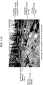
- Fig. 7 is a diagram illustrating an example of luminance of an image that has been shot.
- FIG. 7 A) in an image 10 that has been shot (hereinafter referred to as "original image”) indicates pixels having a luminance corresponding to 18% gray (0 Stop) that is the reference reflectance serving as the reference for brightness (hereinafter referred to as “reference luminance” or "18% Gray value”).
- B) in 10 indicates pixels having luminance corresponding to 90% reflectance (90% gray) (2.3 Stops).
- C) in 10 indicates pixels having luminance corresponding to 2.3% gray (-3 Stops) that is almost black.
- D) in 10 indicates pixels obtained by shooting the sun, yielding luminance that is extremely bright, having luminance corresponding to 1150% gray (6 Stops).
- E) in 10 indicates pixels obtained by shooting portions with mirror reflection, having luminance corresponding to 290% gray (4 Stops).
- Fig. 8 is a diagram for describing the relationship between a flow of creating a master for SDR-capable home entertainment, a distribution medium, and a display device.
- the original image 10 described in Fig. 7 is an image of which the maximum luminance is 1300 nits. That is to say, in a case of creating a master image (SDR image) corresponding to SDR in which the maximum luminance is 100 nits using the original image 10, an SDR-capable master image cannot be created using the luminance of the original image as it is without conversion, since SDR cannot express pixels having luminance 100 nits or higher. That is to say, in order to create an SDR-capable master image using the original image 10, the luminance of the original image needs to be converted into luminance of a dynamic range that is compatible with SDR.
- knee curve processing is processing where luminance at a certain value or lower is linearly displayed, and luminance at a certain value or higher is attenuated in accordance with the display peak luminance of the display device on which display is to be performed.
- Fig. 9A is a diagram illustrating an example of luminance as a result of having mastered the original image illustrated in Fig. 7 to an SDR image.
- Fig. 9B is a diagram illustrating an example of the relationship between original signal values and SDR signal values, for converting (mastering) original signal values into SDR signal values.
- the original signal values are luminance in a dynamic range of 0 to 1300 nits in the original image 10 (hereinafter referred to as "luminance of original image”)
- SDR signal values are luminance in the SDR luminance range (hereinafter referred to as "SDR luminance").
- pixels having a luminance corresponding to 18% gray (0 Stop) that is the reference reflectance are pixels having the reference luminance that is the reference for brightness, as illustrated in Fig. 9B . Accordingly, in the mastering to SDR image, the luminance of the original image corresponding to 18% gray (18 nits) in the original image 10 is not changed even after converting the original image 10 into the SDR image 11, and is decided as the luminance for SDR.
- the luminance of the original image is not changed in the luminance range at or below the luminance of the original image corresponding to 90% gray (90 nits) in the original image 10 (0 to 90 nits), and is decided as the luminance for SDR, as illustrated in Fig. 9B .
- the luminance of the original image in the luminance range exceeding the luminance of the original image corresponding to 90% gray (90 nits) in the original image 10 is allocated to SDR luminance in the luminance range of 90 to 100 nits by linear conversion, as illustrated in Fig. 9B .
- the luminance of the original image corresponding to 90% gray (90 nits) in the original image 10 is not changed even after converting the original image 10 into the SDR image 11, and is decided as the luminance for SDR.
- the luminance of the original image corresponding to 2.3% gray (2 nits) in the original image 10 is not changed even after converting the original image 10 into the SDR image 11, and is decided as the luminance for SDR, in the same way as described above.
- the luminance of the original image corresponding to 1150% gray (1150 nits) in the original image 10 is converted to 100 nits that is the maximum luminance for SDR.
- Fig. 10A is a diagram illustrating an example of luminance as a result of having mastered the original image illustrated in Fig. 7 to an HDR image.
- Fig. 10B is a diagram illustrating an example of the relationship between original signal values and HDR signal values, for converting (mastering) original signal values into HDR signal values.
- HDR signal values are luminance in the HDR luminance range (hereinafter referred to as "HDR luminance"). Note that in the mastering from the original image to an HDR image in this example, allocation of luminance up to 2000 nits as luminance for HDR is permitted, so the luminance of the original image can be maintained without change in the HDR image as well.
- pixels having a luminance corresponding to 18% gray (0 Stop) that is the reference reflectance are pixels having the reference luminance that is the reference for brightness, such as in A) in an HDR image 12, so in the mastering to HDR image, the luminance of the original image corresponding to 18% gray (18 nits) in the original image 10 is not changed even after converting the original image 10 into the HDR image 12, and is decided as the luminance for HDR.
- the luminance of the original image is not changed for each of pixels corresponding to 90% gray (2.3 Stops) as in B) in the HDR image 12, pixels corresponding to 2.3% gray (-3 Stops) as in C) in the HDR image 12, pixels corresponding to 1150% gray (6 Stops) as in D) in the HDR image 12, and pixels corresponding to 290% gray (4 Stops) as in E) in the HDR image 12, for example, and is decided as the luminance for HDR.
- Fig. 11A is a diagram illustrating an example of results of acquiring an HDR image obtained by the mastering in Fig. 10A , and performing luminance conversion for a display device of which second maximum luminance is 500 nits.
- Fig. 11B is a diagram illustrating an example of the relationship between HDR signal values and TV signal values, for conversion of HDR signal values into TV signal values.
- the second maximum luminance that the HDR TV can display is restricted to 500 nits. Accordingly, the HDR luminance that the HDR signals represent need to be converted to the display luminance in the luminance range of the display.
- HDR signals are acquired, and luminance corresponding to 18% gray (0 Stop) that is the reference for brightness (reference luminance) is extracted from the acquired HDR signals.
- the HDR signals indicating the luminance in the HDR image 13 have 36 nits as the reference luminance, so it can be known that the creator has intentionally changed the reference luminance. Accordingly, the values of luminance indicated by the HDR signals are maintained without change for luminance corresponding to 90% gray (180 nits) and lower, while the values of luminance indicated by these HDR signals exceeding luminance corresponding to 90% gray (180 nits) is linearly converted to where the first maximum luminance that these HDR signals indicate (HPL: 1300 nits) become the second maximum luminance displayable on the HDR TV (DPL: 500 nits).
- the HDR luminance indicated by the HDR signals is decoded to be the display luminance for HDR signals indicating luminance of a fourth reference value (90 nits) and below that is greater than 36 nits.
- the HDR signals indicating luminance exceeding 90 nits are subjected to linear conversion for HDR luminance from 90 nits to the second maximum luminance (DPL) that is displayable on the HDR TV, so that the first maximum luminance (HPL) is made to correspond to the second maximum luminance (DPL), thereby converting the HDR luminance to display luminance.
- DPL second maximum luminance
- the luminances of pixels A) corresponding to 18% gray in the HDR image 13, pixels B) corresponding to 90% gray in the HDR image 13, and pixels C) corresponding to 2.3% gray in the HDR image 13, are not changed, and the luminance of the HDR image 13 is decided as the display luminance.
- the pixels D) corresponding to 1150% gray in the HDR image 13 446 nits obtained by performing the above-described linear conversion is decided as the display luminance
- the pixels E) corresponding to 290% gray in the HDR image 13 313 nits obtained by performing the above-described linear conversion is decided as the display luminance.
- Fig. 12 is a diagram illustrating a functional block diagram of a display device according to a first embodiment.
- Fig. 13 is a diagram for describing a specific example of conversion processing (first conversion) at a converting unit of a display device.
- a display device 100 has a converter 101 and a display unit 102, as illustrated in Fig. 12 .
- the display device 100 is an HDR display device capable of display HDR video, for example, such as an HDR TV, HDR-capable display, or the like.
- the converter 101 acquires video data including HDR signals and static metadata (peak luminance information per title (The Maximum Content Light Level (MaxCLL)).
- the converter 101 controls the HDR effects in accordance with the acquired static metadata, and performs processing of converting from the PQ curve to the gamma curve in the luminance range that the display unit 102 can handle.
- the converter 101 specifically converts a portion of the PQ curve on up into a gamma curve matching the display peak luminance of the HDR TV (third EOTF), without changing the relative relationship in luminance of the PQ curve in the luminance range of 0 to 800 nits (second EOTF), so as to match the value of MaxCLL (e.g., 800 nits) to the display peak luminance of the HDR TV (e.g., 750 nits), as illustrated in Fig. 13 .
- the converter 101 is realized by a processor, memory storing a program, and so forth, for example.
- the converter 101 performs first conversion of converting the luminance of the video, in which, with regard to the second EOTF that is a part of the PQ curve that is the first EOTF, the maximum luminance of the second EOTF is converted to luminance corresponding to the dynamic range of the third EOTF where the dynamic range of the luminance of the second EOTF has been reduced to match the displayable luminance (e.g., peak luminance) of the display unit 102 of the display device 100.
- the displayable luminance of the display unit 102 in this case specifically is the display peak luminance of the display unit 102.
- the converter 101 does not perform tone mapping processing using a knee curve that requires complicated circuits when displaying, on an HDR TV, video data of HDR contents of which the luminance is defined by the PQ curve, so change in color of the pixels in the video at the converter 101 between before and after the first conversion can be suppressed.
- the first EOTF represents the correlation between HDR luminance and code values.
- the second EOTF is a part of the first EOTF that has been clipped out, as a luminance range where 0 nits is the minimum luminance, and the peak luminance indicated by the peak luminance information included in the acquired video data is the maximum luminance.
- the third EOTF is an EOTF where the dynamic range of luminance of the second EOTF has been reduced so that the maximum luminance of the second EOTF matches the displayable luminance, while maintaining the relative relation of luminance in the second EOTF, by multiplying a value, obtained by dividing the displayable luminance by peak luminance indicated in the peak luminance information, by a variable representing luminance in the second EOTF that is a part of the PQ curve, for example. That is to say, the relative relationship of luminance in the second EOTF is the ratio in sets of multiple luminances and code values correlated by the second EOTF, between multiple luminances correlated with mutually different multiple code values.
- the second EOTF in a case where there are a first pre-conversion luminance on the second EOTF, and a second pre-conversion luminance on the second EOTF that differs from the first pre-conversion luminance, and in a case where the first pre-conversion luminance after conversion is a first post-conversion luminance and the second pre-conversion luminance after conversion is a second post-conversion luminance, conversion is performed such that a first ratio between the first pre-conversion luminance and the second pre-conversion luminance, and a second ratio between the first post-conversion luminance and the second post-conversion luminance, are generally equal (so that the error between the first ratio and second ratio after conversion is within a predetermined threshold value).
- the display unit 102 displays video using the results of the first conversion at the converter 101.
- the display unit 102 is realized by an LCD panel, a backlight, an LCD panel driving circuit, a backlight control circuit, and so forth, for example.
- the display unit 102 can display video of the video data input with the contrast relationship being maintained from the time of creating the contents.
- the display unit 102 at this time displays video where the absolute luminance of each pixel is not maintained, but the contrast ratio among the pixels has been maintained at a luminance different from the absolute luminance at time of creating the contents.
- Fig. 14 is a diagram for describing a specific example of other conversion processing at the converting unit.
- the MaxCLL of the video data of the HDR contents exceeds a predetermined luminance (e.g., 1000 nits)
- a predetermined luminance e.g. 1000 nits
- performing luminance conversion where the relative correlation is maintained up to MaxCLL reduces the rate of reduction as to the luminance of the overall image, so the luminance in a low-luminance range (e.g., luminance 100 nits and lower) before conversion becomes extremely small after conversion. Accordingly, if luminance conversion processing is performed uniformly maintaining the relative relationship of luminance even if the value of the MaxCLL exceeds the predetermined luminance, this may result in the appearance greatly changing due to the low-luminance range becoming too dark, even though the relative relationship of luminance between before and after the conversion processing is maintained.
- first conversion is performed where the relative relationship is maintained for a luminance range equal to or below the predetermined luminance out of the luminances of the video
- second conversion that is the same processing as Super White in SDR is performed handling regions of the predetermined luminance or higher as Sperkle regions.
- the converter 101 performs third conversion where this MaxCLL is set to 1023 that is the upper limit code value (CV) of the full range (see description below), and of the luminances of the video, the luminance in a luminance range from 1000 nits to MaxCLL is linearly expressed, performs fourth conversion where a value corresponding to 1000 nits is set to 940 that is the upper limit code value (CV) of a narrow range (see description below), and of the luminances of the video, the dynamic range of the luminance in a luminance range from 0 nits to 1000 nits is reduced with the relative relationship of luminance maintained in the same way as the first conversion described with reference to Fig.
- the converter 101 performs first conversion where the MaxCLL is set to 940 that is the upper limit code value (CV) of narrow range.
- the converter 101 performs first determining of whether or not the peak luminance indicated by the peak luminance information exceeds a predetermined luminance (e.g., 1000 nits) stored in the display device 100 beforehand, and selectively performs one of the first conversion and second conversion in accordance with the results of the first determining. Specifically, in a case where the peak luminance is found to exceed the predetermined luminance as a result of the first determining, the second conversion that differs from the first conversion is performed.
- the second conversion is conversion including the third conversion where luminance is converted in a luminance range from the predetermined luminance to the peak luminance, and fourth conversion where luminance is converted in a luminance range from 0 nits to the predetermined luminance.
- the luminance of video in the luminance range from the predetermined luminance of the second EOTF to the peak luminance indicated by the peak luminance information is converted to luminance in a luminance range from the first luminance corresponding to 940 that is the upper limit of the narrow range of code values to the second luminance 1023 that is the upper limit value of the full range of code values.
- the luminance in a luminance range from the predetermined luminance of the second EOTF to the peak luminance is converted so that a linear relationship is satisfied between a set of the first luminance and the upper limit value of the narrow range, and a set of the second luminance and the upper limit value of the fill range.
- full range is a range stipulating code values of the fourth EOTF stored by the display device 100 beforehand, and is a range of integer values from 0 through 1023 for example, in a case the code values are 10-bit stipulated. That is to say, the full range is a range where the minimum value through the maximum value of integer values that can express the code values of luminance by bit length are used.
- the narrow range is a range narrower than the full range, and is a range of integer values from 64 through 940 for example, in a case the code values are 10-bit stipulated. That is to say, the narrow range is a range where integer values, of a narrower range than full range, of inerter values that can express the code values of luminance by bit length are used.
- a fifth EOTF that is part of the second EOTF and is the part of the luminance range where the predetermined luminance is the maximum luminance is converted to a sixth EOTF, where the dynamic range of luminance of the fifth EOTF is reduced with the maximum luminance of luminance of the fifth EOTF matching the first luminance, while maintaining the relative relationship of the fifth EOTF, and luminance of the dynamic range of the fifth EOTF of the video is converted to the dynamic range of the sixth EOTF.
- the converter 101 performs conversion where the dynamic range of the luminance of the second EOTF is reduced to match the peak luminance to the first luminance serving as the displayable luminance, as first conversion.
- the display unit 102 displays video using the result of the first conversion or the result of the second conversion.
- the dynamic range of luminance of video compatible with HDR can be converted to match the display peak luminance of the display device, without performing luminance conversion processing such as knee curve processing. Accordingly, luminance conversion of video of video data compatible with HDR to match the display peak luminance of the display device can be easily performed, and change in color between before and after conversion can be suppressed.
- second conversion rather than first conversion is performed in a case where the result of the first determining finds that the peak luminance exceeds the predetermined luminance. Accordingly, in a case where the peak luminance exceeds the predetermined luminance, luminance conversion processing with the relative relationship of luminance maintained (first conversion) is not performed, thereby suppressing a situation where the appearance greatly changes due to the low-luminance range becoming too dark, even though the relative relationship of luminance between before and after the conversion processing of luminance is maintained.
- the firs conversion is performed rather than the second conversion, so even easier conversion processing can be performed in a case where there is little possibility that the appearance will greatly change before and after the conversion processing. Accordingly, the processing load can be reduced.
- the predetermined luminance may be decided in accordance with the value of the maximum frame average luminance information (MaxFALL: The Maximum Frame-Average Light Level) indicating the maximum frame average luminance that is the maximum value of average luminance of each of multiple frames making up the video.
- the maximum frame average luminance information is information included in static metadata included in the video data.
- the converter 101 performs second determining to determine whether or not the maximum frame average luminance indicated by the maximum frame average luminance information is 1/2 or the peak luminance or lower. In a case where there result of the second determining finds that the maximum frame average luminance is 1/2 the peak luminance or lower, the second conversion is performed using a value double the maximum frame average luminance as the predetermined luminance.
- first conversion or second conversion may be performed using dynamic metadata corresponding to each of multiple sectional videos (cuts, series of sequences) making up the video of the video data for this content, instead of the MaxCLL that is static metadata.
- dynamic metadata is sectional peak luminance information (The Maximum Sequence Light Level: MaxSLL) indicating the peak luminance of this sectional video (sectional peak luminance), for each of multiple sectional videos. Accordingly, HDR contents can be displayed using peak luminance of the HDR TV more efficiently.
- the luminance of that sectional video may be displayed as it is, maintaining the relative relationship and not performing conversion processing of extending in the direction of being brighter.
- sectional peak luminance corresponding to each sectional video is markedly lower than the peak luminance (e.g., 1/2 or below), or in a case where the sectional peak luminances of consecutive sectional videos markedly differ (difference of 50% or more), performing the above processing as it is may result in the low-luminance range (dark portions) becoming suddenly bright and unity of the overall image may be lost. Accordingly, sudden change in luminance may be suppressed by not using the sectional peak luminance as it is, but performing correction on the sectional peak luminance (MaxSLL) such as (MaxCLL + MaxSLL) / 2, (MaxSLL (x) + MaxSLL (X + 1)) / 2, or the like, and then using the corrected values to perform the above processing.
- MaxSLL sectional peak luminance
- the converter 101 performs third determining to determine whether or not change in luminance between two consecutive sectional videos out of multiple sectional videos is sudden or not, using peak luminance information and sectional peak luminance information included in the acquired video data.
- the converter 101 converts the dynamic range of the luminance of at least one of the two sectional videos so that the change in luminance comes within a predetermined range.
- the converter 101 performs the first conversion in which the EOTF in the dynamic range where the sectional peak luminance indicated by the sectional peak luminance information corresponding to this sectional video is the maximum luminance is the second EOTF, for each of the two sectional videos.
- processing is switched in accordance with whether sudden change in luminance occurs between consecutive sectional videos, so the video can be suppressed from suddenly becoming dark or becoming bright, and loosing unity of the overall video can be suppressed.
- the display method of reducing the dynamic range of luminance of video in HDR contents to display on an HDR TV has the following issues, unlike a case of changing the dynamic range of luminance of video in SDR contents to display on an SDR TV.
- Fig. 15 is a diagram for describing an example of display processing in a case of displaying SDR signals on an SDR TV, in accordance with the brightness of the viewing atmosphere.
- SDR TV quantizes SDR signals of SDR contents using an SDR EOTF (gamma curve) to maintain relative luminance (contrast ratio) not absolute luminance in display.
- SDR EOTF gamma curve
- a dimming device is provided to the SDR TV, and the contrast ratio between dark portions and bright portions in the SDR contents is maintained in accordance with the brightness of the viewing environment of the SDR TV, by automatically changing the light emission intensity of the backlight of the display unit in accordance with the brightness of the viewing environment acquired by the dimming device.
- the display control is changed in accordance with whether the viewing environment is a dark room or a bright room.
- the SDR TV has capabilities to display the display peak luminance at a luminance (e.g., 250 nits) exceeding 100 nits that is the peak luminance of the dynamic range of the luminance of the EOTF of SDR (gamma curve).
- the displayed peak luminance is suppressed to 100 nits as illustrated in (b-1) in (b) in Fig. 15 .
- the displayed peak luminance is extended to the maximal 250 nits as illustrated in (b-2) in (b) in Fig. 15 .
- the luminance of video of SDR signals in SDR contents is managed by relative luminance in SDR TV, so changing of the peak luminance of video to be displayed on the SDR TV in accordance with the brightness of the viewing environment while maintaining the relative luminance is easy.
- HDR TV where video of HDR signals obtained by the absolute luminance of shot video being quantized by the PQ curve, to not be displayed by absolute luminance but to perform display control where the dynamic range of luminance of the video is changed in accordance with the brightness of the viewing environment (dark room, dark room, somewhat bright room, etc.). That is to say, there is demand for HDR TV to be able to provide viewers with maximally similar HDR effects even if the brightness of the viewing environment changes, by performing display control to perform display while maintaining an appropriate contrast ratio, the same as with SDR TV.
- HDR video of HDR contents is created by the content creator assuming display by absolute luminance, so even if the method of converting the luminance of the video while maintaining the relative luminance of luminance of the video as it is, is directly applied to HDR signal video, displaying video of appropriate luminance on the display unit is difficult.
- the peak luminance is often around 800 to 4000 nits, exceeding the peak luminance of normal HDR TVs. Accordingly, there is the need to set the light emission intensity of the backlight to maximum in order to display peak luminance of HDR video even in a dark viewing environment, so adjustment in accordance with the viewing environment is difficult by backlight control alone.
- the dynamic range of luminance of the EOTF of HDR is 0 to 10,000 nits
- the dynamic range of luminance of the EOTF of SDR is 0 to 100 nits
- the dynamic range of luminance of the EOTF of HDR is 100 times greater than the EOTF of SDR.
- the contents themselves can be displayed on the display device using 0 through 100 nits in full in the case of SDR video, it is rare for display to be made on the display device using the dynamic range of luminance from 0 to 10,000 nits in the case of HDR video, and the possibility of displaying video having peak luminance of around 800 to 4000 nits on the display device is high.
- Fig. 16 is a block diagram illustrating functional blocks of a display device according to the second embodiment.
- a display device 100a includes a converter 101a, the display unit 102, and a viewing environment light input unit 103, as illustrated in Fig. 16 .
- the display unit 102 has the same configuration as the display unit 102 of the display device 100 in the first embodiment, so detailed description will be omitted.
- the viewing environment light input unit 103 detects the intensity of environment light in the space where the display device 100a is installed (i.e., the brightness of the viewing environment), and sends the detection results to the converter 101a.
- the viewing environment light input unit 103 is realized by an illuminance sensor or the like, for example.
- the converter 101a performs fourth determining to determine whether or not the environment light is bright, in accordance with the intensity of the environment light detected by the viewing environment light input unit 103. In a case where the result of the fourth determining is that the environment light is bright, the converter 101a performs conversion using a seventh EOTF as the third EOTF, as the first conversion.
- the seventh EOTF is an EOTF where the dynamic range of luminance of the second EOTF has been reduced to match displayable luminance which is the display peak luminance of the display device.
- the converter 101a performs conversion using an eighth EOTF as the third EOTF, as the first conversion.
- the eighth EOTF is an EOTF where the dynamic range of the second EOTF has been reduced to match a luminance lowered by a predetermined percentage of luminance from the peak luminance of the display device.
- the emission intensity of the backlight of the display unit 102 is not set to maximum but is set to emission intensity reduced by 20%, for example, from the maximum emission intensity of the backlight. Also, in a case where the detected intensity of the environment light exceeds the predetermined threshold value, and the viewing environment is determined to be bright, the emission intensity of the backlight of the display unit 102 is set to maximum. Note that in a case where the viewing environment is determined to be dark, the first conversion is performed matching a luminance reduced by 20% from the display peak luminance, and in a case where the viewing environment is determined to be bright, the first conversion is performed matching the display peak luminance.
- display in accordance with the brightness of the viewing environment can be easily realized even in a case of displaying HDR video, regarding which display at absolute luminance is assumed, on an HDR TV.
- the components of the above embodiments may be realized by dedicated hardware, or may be realized by a software program suitable for the components being executed.
- the components may be realized by a program executing unit such as a CPU or another processor or the like reading out and executing the software program recorded in a recording medium such as a hard disk, semiconductor memory, or the like.
- Software realizing the display method and so forth in the above embodiments is a program such as follows.
- the program causes a computer to execute a display method of displaying, on a display device, video of video data where luminance of video is defined by a first EOTF (Electro-Optical Transfer Function) indicating a correlation of HDR (High Dynamic Range) luminance and code values.
- the video data includes peak luminance information indicating peak luminance of the video.
- the method includes: acquiring the video data; performing first conversion where the luminance of the video is converted to a luminance corresponding to a dynamic range of a third EOTF, where, with regard to a second EOTF that is part of the first EOTF and is the part of a luminance range where the peak luminance indicated by the peak luminance information included in the acquired video data is the maximum luminance, the dynamic range of luminance of the second EOTF is reduced with the maximum luminance of the second EOTF matching the displayable luminance of the display device, while maintaining the relative relationship of luminance of the second EOTF; and displaying the video on the display device using the result of the first conversion.
- the present disclosure is useful as a display method, display device, and so forth that enables luminance conversion to be easily performed for video of video data corresponding to HDR in accordance with display peak luminance, and enables change in color between before and after conversion to be suppressed.
- Reference Signs List
- the third EOTF is an EOTF where the dynamic range of luminance of the second EOTF is reduced with the maximum luminance of the second EOTF matching the displayable luminance, while maintaining the relative relationship of luminance of the second EOTF, by multiplying a value, obtained by dividing the displayable luminance by the peak luminance, by a variable representing luminance in the second EOTF.
- the video data further includes maximum frame average luminance information indicating maximum frame average luminance that is a maximum value of average luminance of each of a plurality of frames making up the video, wherein second determining is performed of whether or not the maximum frame average luminance that the maximum frame average luminance information indicates is 1/2 of the peak luminance or lower, and wherein, in a case where the maximum frame average luminance is found to be 1/2 of the peak luminance or lower as a result of the second determining, the second conversion is performed using a value that is double the maximum frame average luminance, as the predetermined luminance.
- the video data further includes, for each of a plurality of sectional video making up the video, sectional peak luminance information indicating sectional peak luminance that is peak luminance of that sectional video, the display method further comprising:
- a display device displaying video of video data where luminance of video is defined by a first EOTF (Electro-Optical Transfer Function) indicating a correlation of HDR (High Dynamic Range) luminance and code values, wherein the video data includes peak luminance information indicating peak luminance of the video, the display device comprising:
Landscapes
- Engineering & Computer Science (AREA)
- Multimedia (AREA)
- Signal Processing (AREA)
- Human Computer Interaction (AREA)
- Databases & Information Systems (AREA)
- Picture Signal Circuits (AREA)
- Controls And Circuits For Display Device (AREA)
- Transforming Electric Information Into Light Information (AREA)
- Processing Of Color Television Signals (AREA)
- Control Of Indicators Other Than Cathode Ray Tubes (AREA)
Applications Claiming Priority (4)
| Application Number | Priority Date | Filing Date | Title |
|---|---|---|---|
| US201562160016P | 2015-05-12 | 2015-05-12 | |
| JP2015248025A JP6731722B2 (ja) | 2015-05-12 | 2015-12-18 | 表示方法および表示装置 |
| PCT/JP2016/000626 WO2016181584A1 (ja) | 2015-05-12 | 2016-02-08 | 表示方法および表示装置 |
| EP16792319.2A EP3297288B1 (en) | 2015-05-12 | 2016-02-08 | Display method and display device |
Related Parent Applications (2)
| Application Number | Title | Priority Date | Filing Date |
|---|---|---|---|
| EP16792319.2A Division EP3297288B1 (en) | 2015-05-12 | 2016-02-08 | Display method and display device |
| EP16792319.2A Division-Into EP3297288B1 (en) | 2015-05-12 | 2016-02-08 | Display method and display device |
Publications (1)
| Publication Number | Publication Date |
|---|---|
| EP3731532A1 true EP3731532A1 (en) | 2020-10-28 |
Family
ID=57551947
Family Applications (2)
| Application Number | Title | Priority Date | Filing Date |
|---|---|---|---|
| EP20179890.7A Withdrawn EP3731532A1 (en) | 2015-05-12 | 2016-02-08 | Conversion of high dynamix range (hdr) luminance |
| EP16792319.2A Active EP3297288B1 (en) | 2015-05-12 | 2016-02-08 | Display method and display device |
Family Applications After (1)
| Application Number | Title | Priority Date | Filing Date |
|---|---|---|---|
| EP16792319.2A Active EP3297288B1 (en) | 2015-05-12 | 2016-02-08 | Display method and display device |
Country Status (5)
| Country | Link |
|---|---|
| US (2) | US10462407B2 (es) |
| EP (2) | EP3731532A1 (es) |
| JP (1) | JP6731722B2 (es) |
| CN (2) | CN111491148B (es) |
| MX (1) | MX369783B (es) |
Families Citing this family (29)
| Publication number | Priority date | Publication date | Assignee | Title |
|---|---|---|---|---|
| WO2015130797A1 (en) * | 2014-02-25 | 2015-09-03 | Apple Inc. | Adaptive transfer function for video encoding and decoding |
| JP6421504B2 (ja) * | 2014-07-28 | 2018-11-14 | ソニー株式会社 | 画像処理装置及び画像処理方法 |
| JP6559803B2 (ja) * | 2015-12-25 | 2019-08-14 | シャープ株式会社 | 表示装置、表示装置の制御方法、制御プログラム、および記録媒体 |
| CN109074775B (zh) * | 2016-01-29 | 2022-02-08 | 巴科股份有限公司 | 数字图像处理链和处理块以及包括它们的显示器 |
| JP2018013696A (ja) * | 2016-07-22 | 2018-01-25 | キヤノン株式会社 | 画像処理装置および表示装置 |
| JP6957332B2 (ja) * | 2017-01-17 | 2021-11-02 | キヤノン株式会社 | 画像処理装置および画像処理方法 |
| KR102308192B1 (ko) | 2017-03-09 | 2021-10-05 | 삼성전자주식회사 | 디스플레이 장치 및 그 제어 방법 |
| US10212456B2 (en) * | 2017-06-02 | 2019-02-19 | Apple Inc. | Deblocking filter for high dynamic range (HDR) video |
| JP2019005973A (ja) * | 2017-06-22 | 2019-01-17 | キヤノン株式会社 | 印刷制御装置およびその制御方法 |
| US10735688B2 (en) * | 2017-07-13 | 2020-08-04 | Samsung Electronics Co., Ltd. | Electronics apparatus, display apparatus and control method thereof |
| JP2019047223A (ja) * | 2017-08-30 | 2019-03-22 | シャープ株式会社 | 変換装置、変換方法、表示装置、プログラム、および記録媒体 |
| CN111183651A (zh) * | 2017-10-12 | 2020-05-19 | 索尼公司 | 图像处理设备、图像处理方法、发送设备、发送方法和接收设备 |
| JP6723969B2 (ja) | 2017-11-06 | 2020-07-15 | 株式会社ソニー・インタラクティブエンタテインメント | 画像処理装置、表示装置、および画像処理方法 |
| TWI650998B (zh) * | 2017-12-15 | 2019-02-11 | 晨星半導體股份有限公司 | 應用在機上盒的格式轉換電路及相關的方法 |
| EP3734954B1 (en) * | 2017-12-27 | 2023-03-22 | Panasonic Intellectual Property Management Co., Ltd. | Display device and display method |
| WO2019138942A1 (ja) * | 2018-01-10 | 2019-07-18 | シャープ株式会社 | 表示装置、表示方法、及び表示制御プログラム |
| JP7071137B2 (ja) * | 2018-01-26 | 2022-05-18 | キヤノン株式会社 | 電子機器およびその制御方法 |
| US10832613B2 (en) | 2018-03-07 | 2020-11-10 | At&T Intellectual Property I, L.P. | Image format conversion using luminance-adaptive dithering |
| US20200045341A1 (en) * | 2018-07-31 | 2020-02-06 | Ati Technologies Ulc | Effective electro-optical transfer function encoding for limited luminance range displays |
| US20200192548A1 (en) * | 2018-12-13 | 2020-06-18 | Ati Technologies Ulc | Methods and apparatus for displaying a cursor on a high dynamic range display device |
| EP3672254A1 (en) * | 2018-12-21 | 2020-06-24 | InterDigital VC Holdings, Inc. | Decoding an image |
| JP7344654B2 (ja) * | 2019-03-07 | 2023-09-14 | キヤノン株式会社 | 撮像装置及び再生装置及びそれらの制御方法及びプログラム |
| JP7332325B2 (ja) * | 2019-04-15 | 2023-08-23 | キヤノン株式会社 | 画像処理装置、撮像装置、画像処理方法、及びプログラム |
| JP2022542312A (ja) | 2019-07-30 | 2022-09-30 | ドルビー ラボラトリーズ ライセンシング コーポレイション | 電気-光伝達関数変換及び信号適法化 |
| KR102640015B1 (ko) * | 2019-12-31 | 2024-02-27 | 엘지디스플레이 주식회사 | 표시 장치 및 그 구동 방법 |
| JP7475187B2 (ja) | 2020-04-15 | 2024-04-26 | キヤノン株式会社 | 表示制御装置および方法、プログラム、記憶媒体 |
| US11412174B2 (en) | 2020-09-22 | 2022-08-09 | Microsoft Technology Licensing, Llc | Efficient electro-optical transfer function (EOTF) curve for standard dynamic range (SDR) content |
| CN113870769B (zh) * | 2021-09-23 | 2023-03-21 | 深圳市艾比森光电股份有限公司 | 显示屏系统的数据处理方法和系统 |
| WO2023085795A1 (ko) * | 2021-11-15 | 2023-05-19 | 엘지전자 주식회사 | 영상표시기기 및 그 제어 방법 |
Citations (3)
| Publication number | Priority date | Publication date | Assignee | Title |
|---|---|---|---|---|
| JP2008167418A (ja) | 2006-12-05 | 2008-07-17 | Nippon Hoso Kyokai <Nhk> | 画像信号処理装置 |
| WO2014128586A1 (en) * | 2013-02-21 | 2014-08-28 | Koninklijke Philips N.V. | Improved hdr image encoding and decoding methods and devices |
| WO2015034188A1 (ko) * | 2013-09-06 | 2015-03-12 | 엘지전자 주식회사 | 디지털 방송 시스템에서 광역 밝기 표현을 위한 초고화질 방송 신호 송수신 방법 및 장치 |
Family Cites Families (16)
| Publication number | Priority date | Publication date | Assignee | Title |
|---|---|---|---|---|
| TW201021018A (en) * | 2008-11-21 | 2010-06-01 | Chunghwa Picture Tubes Ltd | Color correction method and related device for liquid crystal display |
| US8525933B2 (en) * | 2010-08-02 | 2013-09-03 | Dolby Laboratories Licensing Corporation | System and method of creating or approving multiple video streams |
| WO2012142285A2 (en) * | 2011-04-12 | 2012-10-18 | Dolby Laboratories Licensing Corporation | Quality assessment for images that have extended dynamic ranges or wide color gamuts |
| EP2702766B1 (en) * | 2011-04-28 | 2017-06-14 | Koninklijke Philips N.V. | Apparatuses and methods for hdr image encoding and decoding |
| EP2745507A1 (en) * | 2011-09-27 | 2014-06-25 | Koninklijke Philips N.V. | Apparatus and method for dynamic range transforming of images |
| CN102427517B (zh) * | 2011-09-30 | 2017-05-31 | 青岛海信电器股份有限公司 | 动态对比度的调整方法及装置、液晶电视机 |
| WO2013059116A1 (en) * | 2011-10-20 | 2013-04-25 | Dolby Laboratories Licensing Corporation | Method and system for video equalization |
| RU2665211C1 (ru) * | 2011-12-06 | 2018-08-28 | Долби Лэборетериз Лайсенсинг Корпорейшн | Устройство и способ улучшения обмена данными изображения на основе нелинейности восприятия яркости между разными возможностями отображения |
| PL2836983T3 (pl) * | 2012-10-08 | 2018-01-31 | Koninklijke Philips Nv | Przetwarzanie obrazu zmieniające luminancję z ograniczeniami barwy |
| CN103915077B (zh) * | 2013-01-04 | 2017-06-20 | 李卫斌 | 一种在普通显示设备上显示高动态图像的方法 |
| KR20160013023A (ko) * | 2013-05-23 | 2016-02-03 | 톰슨 라이센싱 | 비디오 시퀀스를 톤-맵핑하는 방법 |
| JP2015008360A (ja) * | 2013-06-24 | 2015-01-15 | ソニー株式会社 | 再生装置、再生方法、および記録媒体 |
| PL3022902T3 (pl) * | 2013-07-16 | 2020-06-29 | Koninklijke Philips N.V. | Sposób i urządzenie do tworzenia funkcji eotf dla uniwersalnego odwzorowywania kodu dla obrazu hdr |
| TWI632810B (zh) * | 2013-07-19 | 2018-08-11 | 新力股份有限公司 | Data generating device, data generating method, data reproducing device, and data reproducing method |
| JP6202330B2 (ja) * | 2013-10-15 | 2017-09-27 | ソニー株式会社 | 復号装置および復号方法、並びに符号化装置および符号化方法 |
| US10017792B2 (en) * | 2014-07-18 | 2018-07-10 | Alliance For Sustainable Energy, Llc | Biomass conversion to fuels and chemicals |
-
2015
- 2015-12-18 JP JP2015248025A patent/JP6731722B2/ja active Active
-
2016
- 2016-02-08 EP EP20179890.7A patent/EP3731532A1/en not_active Withdrawn
- 2016-02-08 CN CN202010324126.XA patent/CN111491148B/zh active Active
- 2016-02-08 CN CN201680008002.2A patent/CN107211183B/zh active Active
- 2016-02-08 MX MX2017013542A patent/MX369783B/es active IP Right Grant
- 2016-02-08 EP EP16792319.2A patent/EP3297288B1/en active Active
-
2017
- 2017-10-10 US US15/728,550 patent/US10462407B2/en active Active
-
2019
- 2019-09-19 US US16/575,729 patent/US10992898B2/en active Active
Patent Citations (4)
| Publication number | Priority date | Publication date | Assignee | Title |
|---|---|---|---|---|
| JP2008167418A (ja) | 2006-12-05 | 2008-07-17 | Nippon Hoso Kyokai <Nhk> | 画像信号処理装置 |
| WO2014128586A1 (en) * | 2013-02-21 | 2014-08-28 | Koninklijke Philips N.V. | Improved hdr image encoding and decoding methods and devices |
| WO2015034188A1 (ko) * | 2013-09-06 | 2015-03-12 | 엘지전자 주식회사 | 디지털 방송 시스템에서 광역 밝기 표현을 위한 초고화질 방송 신호 송수신 방법 및 장치 |
| US20160173811A1 (en) * | 2013-09-06 | 2016-06-16 | Lg Electronics Inc. | Method and apparatus for transmitting and receiving ultra-high definition broadcasting signal for high dynamic range representation in digital broadcasting system |
Also Published As
| Publication number | Publication date |
|---|---|
| JP2016213809A (ja) | 2016-12-15 |
| US10992898B2 (en) | 2021-04-27 |
| MX2017013542A (es) | 2018-03-07 |
| CN107211183A (zh) | 2017-09-26 |
| US20200014880A1 (en) | 2020-01-09 |
| US10462407B2 (en) | 2019-10-29 |
| JP6731722B2 (ja) | 2020-07-29 |
| EP3297288A4 (en) | 2018-03-21 |
| CN111491148A (zh) | 2020-08-04 |
| CN107211183B (zh) | 2020-05-22 |
| CN111491148B (zh) | 2021-11-12 |
| US20180048845A1 (en) | 2018-02-15 |
| MX369783B (es) | 2019-11-21 |
| EP3297288B1 (en) | 2020-10-14 |
| EP3297288A1 (en) | 2018-03-21 |
Similar Documents
| Publication | Publication Date | Title |
|---|---|---|
| US10992898B2 (en) | Display method and display device | |
| US10891722B2 (en) | Display method and display device | |
| US11423523B2 (en) | Apparatus and method for dynamic range transforming of images | |
| KR102061349B1 (ko) | 높은 다이내믹 레인지 이미지 신호의 생성 및 처리 | |
| US10218952B2 (en) | Architecture for rendering high dynamic range video on enhanced dynamic range display devices | |
| KR102529013B1 (ko) | 컬러 픽처를 인코딩 및 디코딩하는 방법 및 장치 | |
| US20180152686A1 (en) | Tone mapping functions for rendering high dynamic range video on enhanced dynamic range display devices | |
| EP3174280A1 (en) | Conversion method and conversion apparatus | |
| WO2016181584A1 (ja) | 表示方法および表示装置 | |
| JP6980858B2 (ja) | 表示方法および表示装置 | |
| WO2016189774A1 (ja) | 表示方法および表示装置 |
Legal Events
| Date | Code | Title | Description |
|---|---|---|---|
| PUAI | Public reference made under article 153(3) epc to a published international application that has entered the european phase |
Free format text: ORIGINAL CODE: 0009012 |
|
| STAA | Information on the status of an ep patent application or granted ep patent |
Free format text: STATUS: THE APPLICATION HAS BEEN PUBLISHED |
|
| AC | Divisional application: reference to earlier application |
Ref document number: 3297288 Country of ref document: EP Kind code of ref document: P |
|
| AK | Designated contracting states |
Kind code of ref document: A1 Designated state(s): AL AT BE BG CH CY CZ DE DK EE ES FI FR GB GR HR HU IE IS IT LI LT LU LV MC MK MT NL NO PL PT RO RS SE SI SK SM TR |
|
| STAA | Information on the status of an ep patent application or granted ep patent |
Free format text: STATUS: REQUEST FOR EXAMINATION WAS MADE |
|
| 17P | Request for examination filed |
Effective date: 20210420 |
|
| RBV | Designated contracting states (corrected) |
Designated state(s): AL AT BE BG CH CY CZ DE DK EE ES FI FR GB GR HR HU IE IS IT LI LT LU LV MC MK MT NL NO PL PT RO RS SE SI SK SM TR |
|
| STAA | Information on the status of an ep patent application or granted ep patent |
Free format text: STATUS: EXAMINATION IS IN PROGRESS |
|
| 17Q | First examination report despatched |
Effective date: 20211123 |
|
| STAA | Information on the status of an ep patent application or granted ep patent |
Free format text: STATUS: THE APPLICATION HAS BEEN WITHDRAWN |
|
| 18W | Application withdrawn |
Effective date: 20230531 |