EP3731402B1 - Elektrowerkzeug und steuerungsverfahren dafür - Google Patents
Elektrowerkzeug und steuerungsverfahren dafür Download PDFInfo
- Publication number
- EP3731402B1 EP3731402B1 EP20170963.1A EP20170963A EP3731402B1 EP 3731402 B1 EP3731402 B1 EP 3731402B1 EP 20170963 A EP20170963 A EP 20170963A EP 3731402 B1 EP3731402 B1 EP 3731402B1
- Authority
- EP
- European Patent Office
- Prior art keywords
- motor
- voltage
- slope
- power tool
- preset
- Prior art date
- Legal status (The legal status is an assumption and is not a legal conclusion. Google has not performed a legal analysis and makes no representation as to the accuracy of the status listed.)
- Active
Links
- 238000000034 method Methods 0.000 title claims description 42
- 238000001514 detection method Methods 0.000 claims description 26
- 230000000750 progressive effect Effects 0.000 claims 3
- 230000008569 process Effects 0.000 description 18
- 238000004804 winding Methods 0.000 description 4
- 241000196324 Embryophyta Species 0.000 description 2
- 238000010586 diagram Methods 0.000 description 2
- 230000003287 optical effect Effects 0.000 description 2
- 230000002093 peripheral effect Effects 0.000 description 2
- 239000007858 starting material Substances 0.000 description 2
- 241001417527 Pempheridae Species 0.000 description 1
- 230000009471 action Effects 0.000 description 1
- 230000005540 biological transmission Effects 0.000 description 1
- 230000015572 biosynthetic process Effects 0.000 description 1
- 230000008859 change Effects 0.000 description 1
- 230000003247 decreasing effect Effects 0.000 description 1
- 230000004044 response Effects 0.000 description 1
- 239000004576 sand Substances 0.000 description 1
- 238000004904 shortening Methods 0.000 description 1
- 239000000126 substance Substances 0.000 description 1
Images


Classifications
-
- H—ELECTRICITY
- H02—GENERATION; CONVERSION OR DISTRIBUTION OF ELECTRIC POWER
- H02P—CONTROL OR REGULATION OF ELECTRIC MOTORS, ELECTRIC GENERATORS OR DYNAMO-ELECTRIC CONVERTERS; CONTROLLING TRANSFORMERS, REACTORS OR CHOKE COILS
- H02P1/00—Arrangements for starting electric motors or dynamo-electric converters
-
- A—HUMAN NECESSITIES
- A01—AGRICULTURE; FORESTRY; ANIMAL HUSBANDRY; HUNTING; TRAPPING; FISHING
- A01D—HARVESTING; MOWING
- A01D34/00—Mowers; Mowing apparatus of harvesters
- A01D34/006—Control or measuring arrangements
-
- A—HUMAN NECESSITIES
- A01—AGRICULTURE; FORESTRY; ANIMAL HUSBANDRY; HUNTING; TRAPPING; FISHING
- A01D—HARVESTING; MOWING
- A01D34/00—Mowers; Mowing apparatus of harvesters
- A01D34/01—Mowers; Mowing apparatus of harvesters characterised by features relating to the type of cutting apparatus
- A01D34/412—Mowers; Mowing apparatus of harvesters characterised by features relating to the type of cutting apparatus having rotating cutters
- A01D34/63—Mowers; Mowing apparatus of harvesters characterised by features relating to the type of cutting apparatus having rotating cutters having cutters rotating about a vertical axis
- A01D34/76—Driving mechanisms for the cutters
- A01D34/78—Driving mechanisms for the cutters electric
-
- H—ELECTRICITY
- H02—GENERATION; CONVERSION OR DISTRIBUTION OF ELECTRIC POWER
- H02P—CONTROL OR REGULATION OF ELECTRIC MOTORS, ELECTRIC GENERATORS OR DYNAMO-ELECTRIC CONVERTERS; CONTROLLING TRANSFORMERS, REACTORS OR CHOKE COILS
- H02P1/00—Arrangements for starting electric motors or dynamo-electric converters
- H02P1/02—Details of starting control
- H02P1/04—Means for controlling progress of starting sequence in dependence upon time or upon current, speed, or other motor parameter
-
- H—ELECTRICITY
- H02—GENERATION; CONVERSION OR DISTRIBUTION OF ELECTRIC POWER
- H02P—CONTROL OR REGULATION OF ELECTRIC MOTORS, ELECTRIC GENERATORS OR DYNAMO-ELECTRIC CONVERTERS; CONTROLLING TRANSFORMERS, REACTORS OR CHOKE COILS
- H02P1/00—Arrangements for starting electric motors or dynamo-electric converters
- H02P1/16—Arrangements for starting electric motors or dynamo-electric converters for starting dynamo-electric motors or dynamo-electric converters
- H02P1/26—Arrangements for starting electric motors or dynamo-electric converters for starting dynamo-electric motors or dynamo-electric converters for starting an individual polyphase induction motor
- H02P1/28—Arrangements for starting electric motors or dynamo-electric converters for starting dynamo-electric motors or dynamo-electric converters for starting an individual polyphase induction motor by progressive increase of voltage applied to primary circuit of motor
-
- H—ELECTRICITY
- H02—GENERATION; CONVERSION OR DISTRIBUTION OF ELECTRIC POWER
- H02P—CONTROL OR REGULATION OF ELECTRIC MOTORS, ELECTRIC GENERATORS OR DYNAMO-ELECTRIC CONVERTERS; CONTROLLING TRANSFORMERS, REACTORS OR CHOKE COILS
- H02P27/00—Arrangements or methods for the control of AC motors characterised by the kind of supply voltage
- H02P27/04—Arrangements or methods for the control of AC motors characterised by the kind of supply voltage using variable-frequency supply voltage, e.g. inverter or converter supply voltage
- H02P27/06—Arrangements or methods for the control of AC motors characterised by the kind of supply voltage using variable-frequency supply voltage, e.g. inverter or converter supply voltage using dc to ac converters or inverters
- H02P27/08—Arrangements or methods for the control of AC motors characterised by the kind of supply voltage using variable-frequency supply voltage, e.g. inverter or converter supply voltage using dc to ac converters or inverters with pulse width modulation
-
- H—ELECTRICITY
- H02—GENERATION; CONVERSION OR DISTRIBUTION OF ELECTRIC POWER
- H02P—CONTROL OR REGULATION OF ELECTRIC MOTORS, ELECTRIC GENERATORS OR DYNAMO-ELECTRIC CONVERTERS; CONTROLLING TRANSFORMERS, REACTORS OR CHOKE COILS
- H02P6/00—Arrangements for controlling synchronous motors or other dynamo-electric motors using electronic commutation dependent on the rotor position; Electronic commutators therefor
- H02P6/20—Arrangements for starting
-
- A—HUMAN NECESSITIES
- A01—AGRICULTURE; FORESTRY; ANIMAL HUSBANDRY; HUNTING; TRAPPING; FISHING
- A01D—HARVESTING; MOWING
- A01D2101/00—Lawn-mowers
Definitions
- the present disclosure generally relates to power tools, and more particularly to power tools and control methods.
- an increase of the start-up voltage of the motor will result in a larger starting current passing through the motor.
- a significantly large starting current may lead to burnout in the motor or other circuit components.
- the power tool will start slowly with a load, which affects the experience to the user.
- US 2009/0261766 A1 discloses a method for controlling an electric motor fed by a constant voltage supply system, especially a method for controlling a fan motor which is fed by a motor vehicle power supply system using pulse width modulation and which can be connected to the constant voltage supply system via an actuator in the electric circuit of the motor.
- CN107070365A discloses a current amplitude limiting control method applied to the voltage ramp control mode of a solid-state soft starter. Such current limiting control is adopted under a voltage ramp control mode in the start control of a thyristor control-based solid-state soft starter.
- the control method under the voltage ramp control mode, when a current effective value is smaller than a current amplitude limiting set value, voltage boost control is carried out according to the voltage ramp control mode; when the current effective value is larger than the current amplitude limiting set value, the control method shifts to a current amplitude limiting work mode so as to limit the boost action of voltage; and the switching of the current amplitude limiting work mode is performed according to a method in which hysteresis comparison is set according to the effective value of present instantaneous operating current.
- the object of the present disclosure is to provide a power tool and a control method for the power tool capable of starting quickly with a load.
- Such power tool and control method are set out in the appended set of claims.
- the benefits of the present disclosure are avoiding the excessive starting current when the mower starts with a load, shortening the starting time of the mower and improving the user experience.
- the power tools of the present disclosure include but are not limited to the following: power tools such as screwdrivers, electric drills, wrenches, angle grinders, that require speed adjustment; power tools such as sanders that may be used to sand the workpiece; electric hammers and other power tools that may be used for impact.
- the power tools may also be garden tools, such as lawnmowers, snow sweepers, trimmers and chainsaws. Besides, these power tools may be used for other purposes, such as blenders. As long as these power tools employ the substance of the technical solution disclosed below, they shall fall within the protection scope of the present disclosure.
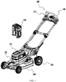
- the lawnmower 100 is taken as an embodiment.
- the lawnmower 100 may be a hand-pushed mower or a riding mower.
- the lawnmower includes a power supply unit 110, a motor 120, a housing 130, a handle 140, wheels 150, a blade (not shown), a deck160.
- the power supply unit 110 is used as a power source to provide kinetic energy for the lawnmower 100.
- the power supply unit 110 is a battery pack, and the battery pack and the housing 130 are detachably coupled.
- the housing 130 is provided with a battery compartment 1311 for receiving the battery pack.
- the battery compartment 1311 is disposed on the upper side of the deck 160.
- the lawnmower 100 includes more than one battery pack.
- the voltage of the battery pack is greater than or equal to 30V. Further, the voltage of the battery pack is greater than or equal to 48V.
- the blade disposed in the deck 160 is used to realize the mowing function.
- the motor 120 is used for driving the blade.
- the motor 120 is operatively coupled to the blade to drive the rotation of the blade, thus achieving the mowing function.
- the blade is directly connected to the motor shaft of the motor 120.
- the blade can be connected to the motor 120 through a transmission device or a deceleration structure.
- the deck 160 is used to carry and install the motor 120.
- the deck 160 is formed with a cutting cavity (not shown).
- the handle 140 is used for being held by a user to facilitate pushing the lawnmower 100.
- the lawnmower 100 also includes a self-propelled motor for driving the wheels 150 to rotate, which can ensure the walking function of the lawnmower 100.
- the lawnmower 100 also includes a power supply circuit 121, a driving circuit 122, a voltage detection unit 123, a rotational speed detection unit 124, a trigger switch 125 and a controller 126.
- the power supply circuit 121 is electrically connected to the power supply unit 110 and is used to convert the power voltage supplied from the power supply unit 110 to each functional circuit.
- the functional circuits mentioned herein include, but are not limited to circuits, chips or electronic devices in the lawnmower 100, which are used to realize functions such as detection, drive, control, calculation, etc.
- the lawnmower 100 may include a plurality of power supply circuits 121 for supplying power to each functional module separately.
- the driving circuit 122 is electrically connected to the motor 120 so that the power supply unit 110 applies the voltage to the motor 120.
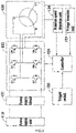
- the motor 120 is a three-phase brushless motor 120, which includes three-phase windings. As shown in FIG.2 , the three-phase windings U, V and W constitute a star connection. In some embodiments, the three-phase windings are connected in an angular formation.
- the driving circuit 122 includes six switching elements configured of FET or IGBT transistors. For the convenience of illustration, taking the IGBT transistor as an embodiment, the gates of the switching elements Q1-Q6 are connected to the controller 126, and the collectors and emitters of the switching elements Q1-Q6 are connected to the three-phase windings. By turning the switching elements Q1-Q6 on and off based on the driving signal outputted from the controller 126, the voltage applied on the motor 120 can be modulated and the rotational speed together with the phase inversion can also be controlled.
- the rotational speed detection unit 124 is configured to detect a rotational speed of the motor 120.
- the rotational speed detection unit 124 includes hall sensors. Three hall sensors are arranged near the rotor at 60 degree intervals along the rotational direction to detect the speed of the motor 120.
- the rotational speed detection unit 124 can also use sensor less methods or other types of sensors, such as an optical or magnetic encoder or a resolver.
- the voltage detection unit 123 is configured to detect a voltage of the motor 120.
- the voltage detection unit 123 includes a voltage sensor and other peripheral circuits connected to the voltage sensor.
- the voltage detection unit 123 is integrated with the controller 126. It should be noted that the voltage detection unit 123 may use any other technical solution capable of detecting the voltage of the motor 120.
- the trigger switch 125 is disposed on the housing 130 that is operatively switched by the user to start the lawnmower 100.
- the trigger switch 125 is a trigger arranged on the housing. After operating the trigger switch 125, the lawnmower 100 is supplied by the power supply unit 110 and enters a start-up stage.
- the controller 126 According to detection signals inputted by the rotational speed detection unit 124 and/or the voltage detection unit 123, the controller 126 generates a corresponding control signal to control the driving circuit 122, so that the corresponding voltage can be outputted to the motor 120 until the lawnmower 100 finishes starting.
- the lawnmower 100 With the trigger switch 125 operated by the user, the lawnmower 100 enters the start-up state.
- the controller 126 controls the driving circuit 122 to apply a voltage to the motor 120 by a first slope while the voltage of the motor 120 is less than the preset voltage V0.
- the voltage detection unit 123 detects the voltage of the motor 120.
- the lawnmower 100 is in the first start-up stage in condition that the voltage of the motor 120 is less than the preset voltage.
- the controller 126 is configured for outputting a control signal to the driving circuit 122, so that the gradually increasing voltage is applied to the motor 120 by the first slope. At this stage, the rotational speed of the motor 120 increases with raising the voltage applied to the motor 120.
- the control signal outputted by the controller 126 is a PWM signal.
- the controller 126 When the lawnmower 100 is in the first start-up stage, the controller 126 outputs the PWM signal whose duty cycle is increased gradually. As shown in FIG.3b , when the lawnmower 100 is in the first start-up stage, the duty cycle of the PWM signal is gradually increased by the first slope.
- the lawnmower 100 When the voltage of the motor 120 is greater than or equal to the preset voltage, the lawnmower 100 is switched from the first start-up stage to the second start-up stage.
- the controller 126 is configured to control the driving circuit 122 to apply a voltage to the motor 120 by a second slope.
- the control signal outputted by the controller 126 is a PWM signal.
- the voltage detection unit 123 detects the voltage of the motor 120. When the voltage of the motor 120 is greater than or equal to the preset voltage value, the controller 126 outputs a PWM signal with a fixed duty cycle to the driving circuit 122. As shown in FIG.3b , the lawnmower 100 is in the second start-up stage at the moment, and the duty cycle of the PWM signal is a fixed value. At this stage, the motor 120 has a specific rotational speed, and the vegetation such as weeds is cut by the blade driven by the motor 120, so that the load of the motor is changed. Besides, the rotational speed of the motor 120 is also changed with the load of the motor 120 (as shown in FIG. 3c ).
- the controller 126 if the voltage of the motor 120 is greater than or equal to the preset voltage, the controller 126 outputs a PWM signal with a duty cycle varied by the second slope to the driving circuit 122. As shown in FIG.4a and FIG.4b , the lawnmower 100 is in the second start-up stage and the duty cycle of the PWM signal changes by the second slope.
- the second slope is greater than or equal to zero and less than or equal to 0.3. If the second slope is 0, that is, the controller 126 outputs a PWM signal with a fixed duty cycle to the driving circuit 122, and the driving circuit 122 applies a fixed voltage to the motor 120. Because the voltage applied to the motor maintains a constant value, it can prevent the generation of an excessive starting current when starting the motor. Also, the blade driven by the motor 120 cuts soft vegetation such as weeds, and the load of the motor 120 will be reduced. With decreasing the load of the motor 120, the rotational speed of the motor 120 is increased, so that the motor 120 can be quickly started. If the second slope is greater than 0.3, the voltage applied to the motor 120 is increased too fast, leading to an excessive starting current and then an increased temperature of the component, which potentially causes the motor 120 and the driving circuit 122 to be burned out.
- the present voltage is obtained.
- the maximum current withstood by the power tool includes the maximum current supported by the driving circuit 122, the maximum current supported by the motor 120, or the maximum current supported by other electronic components.
- the preset voltage is obtained according to the maximum current which could be withstood by the driving circuit 122, and the preset voltage is written to the controller 126.
- a one-to-one relationship between the maximum current which could be withstood by the driving circuit 122 and the preset voltage is established, and save it in the tabular form to a storage unit of the power tool.
- the storage unit could be integrated into the controller 126 or could exist separately.
- the lawnmower 100 When the voltage of the motor reaches the preset voltage, the lawnmower 100 is switched from the first start-up stage to the second start-up stage in order to alter the voltage applied to the motor 120.
- the selection of the preset voltage and the change of the voltage not only shorten the starting time of the motor 120 but also ensure that the starting current is maintained within a range in which the lawnmower 100 can work normally.
- the rotational speed detection unit 124 detects the rotational speed of the motor 120.
- the controller 126 controls the driving circuit 122 for applying a voltage to the motor by a third slope in condition that the rotational speed of the motor 120 is greater than or equal to the preset rotational speed n.
- the control signal outputted by the controller 126 is a PWM signal. If the rotational speed of the motor 120 is greater than or equal to the preset rotational speed n, the controller 126 outputs a PWM signal with a duty cycle varied by the third slope to the driving circuit 122. As shown in FIG.3b , the lawnmower 100 is in the third start-up stage and the duty cycle of the PWM signal changes with the third slope. At this stage, the voltage applied to the motor 120 also gradually increases by the third slope, and the rotational speed of the motor 120 increases until the lawnmower 100 finishes starting.
- the range of the preset speed n is: n ⁇ 60% n0, where n0 is the speed of the motor 120 without load. If the preset speed n is higher than the preset speed of 60%, the voltage applied to the motor 120 maybe too large resulting in an excessive starting current.
- the third slope is greater than or equal to the first slope so that it reduces both the start-up time and the start-up current.
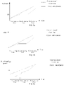
- FIG.3a illustrates the variation curve of the voltage applied to the motor as a function of time
- the dashed line indicates the start-up process of the conventional lawnmower 100 with a load
- the solid line represents the start-up process of the lawnmower 100 with a load as one of the embodiments of the start-up scheme which mentioned above.
- FIG.3b illustrates the variation curve of a PWM signal as a function of time
- the dashed line indicates the start-up process of the conventional lawnmower 100 with a load
- the solid line represents the start-up process of the lawnmower 100 with a load as one of the embodiments of the start-up scheme which mentioned above.
- FIG.3c illustrates the variation curve of the rotational speed of the motor 120 as a function of time
- the dashed line indicates the start-up process of the conventional lawnmower 100 with a load
- the solid line represents the start-up process of the lawnmower 100 with a load as one of the embodiments of the start-up scheme which mentioned above.
- FIG. 3d illustrates the variation curve of the start-up current as a function of time
- the dashed line indicates the start-up process of the conventional lawnmower 100 with a load
- the solid line represents the start-up process of the lawnmower 100 with a load as one of the embodiments of the start-up scheme which mentioned above.
- a lawnmower starting with a load compared with the conventional scheme of a lawnmower starting with a load, adopting the scheme of the lawnmower starting with a load that described in this disclosure can result in a low current of the lawnmower during the process of starting with a load, prevent the lawnmower from frequent starting due to an excessive start-up current during the process of starting with a load, and also reduce the start-up time of the lawnmower.
- the scheme described in this disclosure is especially suitable for starting the lawnmower under heavy load.
- step of S501 the voltage V of the motor is detected.
- the voltage detection unit detects the voltage of the motor.
- the voltage of the motor can be either the phase voltage or the bus voltage.
- the voltage detection unit includes a voltage sensor and other peripheral circuits connected to the voltage sensor. In some embodiments, the voltage detection unit is integrated with the controller.
- step of S502 it is determined whether the voltage of the motor is greater than or equal to the preset voltage V0; if the voltage of the motor is greater than or equal to the preset voltage V0, the process goes to step S504; if the voltage of the motor is less than the preset voltage V0, the process goes to S503.
- the voltage of the motor inputted by the voltage detection unit in the controller is compared with the preset voltage V0 to output corresponding control signals to the driving circuit.
- the present voltage is obtained.
- the maximum current withstood by the power tool includes the maximum current supported by the driving circuit, the maximum current supported by the motor or the maximum current supported by other electronic components.
- the preset voltage is obtained based on the maximum current which could be withstood by the driving circuit, and the value of the preset voltage is written to the controller. In some embodiments, a one-to-one relationship between the maximum current that the driving circuit can withstand and the preset voltage is established, and save it in the tabular form to a storage unit of the power tool.
- the storage unit could be integrated into the controller or could exist separately.
- step of S503 the driving circuit is controlled to apply a voltage to the motor by the first slope.
- the controller outputs a control signal for the driving circuit to apply a voltage to the motor by the first slope.
- the control signal outputted by the controller is a PWM signal.
- step of S504 the driving circuit is controlled to apply a voltage to the motor with the second slope.
- the controller outputs a control signal to enable the driving circuit to apply a voltage to the motor by the second slope.
- the control signal outputted by the controller is a PWM signal.
- the PWM signal changes by the second slope.
- the range of the second slope is greater than or equal to zero and less than or equal to 0.3.
- step of S505 the speed of the motor is detected.
- the rotational speed detection unit detects the rotational speed of the motor.
- the rotational speed detection unit includes hall sensors. Three hall sensors are arranged near the rotor at 60 degree intervals along the rotational direction to detect the speed of the motor.
- the rotational speed detection unit can also use sensor less methods or other types of sensors, such as an optical or magnetic encoder or a resolver.
- step of S506 it is determined whether the rotational speed of the motor is greater than or equal to the preset rotational speed if the rotational speed of the motor is greater than or equal to the preset rotational speed, the process goes to step S507, and if the rotational speed of the motor is less than the preset rotational speed, the process goes to step S505.
- the controller outputs a control signal to the driving circuit according to the motor speed detected by the speed detection unit.
- the range of the preset speed n is: n ⁇ 60% n0, and n0 is the speed of the motor without load.
- step of S507 the driving circuit is controlled to apply a voltage to the motor with the third slope.
- the controller outputs a control signal to enable the driving circuit to apply a voltage to the motor with a third slope.
- the control signal outputted by the controller is a PWM signal.
- the third slope is greater than the second slope.
- FIG. 6 another method for starting the lawnmower with a load is performed according to the steps below.
- step of S601 the voltage V of the motor is detected.
- step of S602 the rotational speed of the motor is detected.
- step of S603 it is determined whether the voltage of the motor is greater than or equal to the preset voltage; if the voltage of the motor is greater than or equal to the preset voltage, the process goes to step S604; if the voltage of the motor is less than the preset voltage, the process goes to S605.
- step of S604 the driving circuit is controlled to apply a voltage to the motor 120 by the second slope, wherein the range of the second slope is greater than or equal to zero and less than or equal to 0.3.
- step of S605 the driving circuit is controlled to apply a voltage to the motor 120 with the first slope.
- step of S606 it is determined whether the rotational speed of the motor s greater than or equal to the preset rotational speed, if the rotational speed of the motor is greater than or equal to the preset rotational speed, the process goes to step S607, and if the rotational speed of the motor is less than the preset rotational speed, the process goes to step S603.
- the range of the preset speed n is: n ⁇ 60% n0, wherein n0 is the speed of the motor 120 without load.
- step of S607 the driving circuit is controlled to apply a voltage to the motor 120 by the third slope.
- the starting method for the lawnmower with a load described in FIG.6 is different than the starting method for the lawnmower with a load described in FIG.5 in that the voltage V and the rotational speed of the motor 120 can be detected simultaneously. And it is not described here.
Landscapes
- Engineering & Computer Science (AREA)
- Power Engineering (AREA)
- Life Sciences & Earth Sciences (AREA)
- Environmental Sciences (AREA)
- Harvester Elements (AREA)
Claims (10)
- Elektrowerkzeug (100), umfassend:einen Motor (120);eine Stromversorgungseinheit (110) für die Versorgung des Motors mit Energie;eine Antriebsschaltung (122), die elektrisch mit dem Motor verbunden ist, sodass die Stromversorgungseinheit eine Spannung an den Motor anlegen kann; undeine Steuereinheit (126), die so ausgelegt ist, dass sie die Antriebsschaltung steuert, um eine Spannung an den Motor anzulegen; dadurch gekennzeichnet, dass sie ferner umfasst:eine Spannungserkennungseinheit (123) zum Erfassen der Spannung;eine Drehzahlerfassungseinheit (124) zur Erfassung der Motordrehzahl;undeinen Triggerschalter (125), der so ausgelegt ist, dass er die Antriebsschaltung in die Lage versetzt, mit dem Anlegen einer Spannung an den Motor zu beginnen, wobei die Steuereinheit dafür ausgelegt ist,die Antriebsschaltung so zu steuern, dass die Spannung an den Motor mit einer ersten Steigung angelegt wird, wenn die Spannung des Motors unter einer voreingestellten Spannung liegt;die Antriebsschaltung so zu steuern, dass die Spannung an den Motor mit einer zweiten Steigung angelegt wird, wenn die Spannung des Motors größer oder gleich der voreingestellten Spannung ist und die Drehzahl des Motors kleiner als eine voreingestellte Drehzahl ist; unddie Antriebsschaltung so zu steuern, dass die Spannung mit einer dritten Steigung angelegt wird, wenn die Drehzahl des Motors größer oder gleich der voreingestellten Drehzahl ist; undwobei die zweite Steigung im Bereich von 0 bis 0,3 liegt, die dritte Steigung größer ist als die zweite Steigung und die erste Steigung kleiner oder gleich der dritten Steigung ist.
- Elektrowerkzeug nach Anspruch 1, wobei:
der Wertebereich der voreingestellten Drehzahl ist: n≤60%n0, wobei n0 die Drehzahl des Motors ohne Last ist. - Elektrowerkzeug nach Anspruch 1, wobei:
die Steuereinheit dafür ausgelegt ist, dass sie die voreingestellte Spannung in Abhängigkeit von einem Maximalstrom bestimmt, dem ein interner Schaltkreis des Elektrowerkzeugs standhält. - Elektrowerkzeug nach Anspruch 1, wobei:
die Steuereinheit die voreingestellte Spannung auf der Grundlage von mindestens einer der folgenden Bedingungen auswählt:
ein Maximalstrom, dem die Antriebsschaltung standhält; und eine Belastung des Motors. - Elektrowerkzeug nach Anspruch 1, wobei:die Antriebsschaltung einen Netzschalter (Q1 - Q6) enthält;die Steuereinheit das Ein- und Ausschalten des Netzschalters durch Pulsweitenmodulation steuert, damit die Antriebsschaltung eine Spannung mit einer zweiten Steigung an den Motor anlegen kann.
- Elektrowerkzeug nach Anspruch 1, wobei:
die Stromversorgungseinheit ein Akkupack ist, der abnehmbar mit dem Elektrowerkzeug verbunden ist, und die Spannung des Akkupacks ist größer oder gleich 30 V. - Elektrowerkzeug nach Anspruch 1, wobei das Elektrowerkzeug ein Rasenmäher ist.
- Steuerungsverfahren für ein Elektrowerkzeug (100), das mit einer Last startet, wobei das Elektrowerkzeug einen Motor (120) umfasst, dadurch gekennzeichnet, dass das Steuerungsverfahren umfasst:Erfassen einer Spannung des Motors;Erfassen einer Drehzahl des Motors;Anlegen progressiver Spannungsanstiege an den Motor mit einer ersten Steigung, wenn sich das Elektrowerkzeug in einer ersten Anlaufphase befindet;Anlegen progressiver Spannungsanstiege an den Motor mit einer zweiten Steigung, wenn sich das Elektrowerkzeug in einer zweiten Anlaufphase befindet; undAnlegen progressiver Spannungsanstiege an den Motor mit einer dritten Steigung, wenn sich das Elektrowerkzeug in einer dritten Anlaufphase befindet;wobei das Elektrowerkzeug von der ersten Anlaufphase auf die zweite Anlaufphase umschaltet, wenn die Spannung des Motors größer oder gleich einer voreingestellten Spannung ist und die Drehzahl des Motors kleiner als eine voreingestellte Drehzahl ist, und das Elektrowerkzeug schaltet von der zweiten Anlaufphase auf die dritte Anlaufphase um, wenn die Drehzahl des Motors größer oder gleich der voreingestellten Drehzahl ist; undwobei die zweite Steigung im Bereich von 0 bis 0,3 liegt, die dritte Steigung größer ist als die zweite Steigung, und die erste Steigung ist kleiner oder gleich der dritten Steigung.
- Steuerungsverfahren für das Elektrowerkzeug nach Anspruch 8, bei dem die voreingestellte Spannung in Abhängigkeit von einem maximalen Strom, dem das Elektrowerkzeug standhält, oder von der Belastung des Motors ermittelt wird.
- Steuerungsverfahren für das Elektrowerkzeug nach Anspruch 8, wobei der Wertebereich der voreingestellten Drehzahl n ist: n≤60%n0, wobei n0 die Drehzahl des Motors ohne Last ist.
Applications Claiming Priority (1)
| Application Number | Priority Date | Filing Date | Title |
|---|---|---|---|
| CN201910346514.5A CN111865145A (zh) | 2019-04-26 | 2019-04-26 | 电动工具及其控制方法 |
Publications (2)
| Publication Number | Publication Date |
|---|---|
| EP3731402A1 EP3731402A1 (de) | 2020-10-28 |
| EP3731402B1 true EP3731402B1 (de) | 2022-05-25 |
Family
ID=70417378
Family Applications (1)
| Application Number | Title | Priority Date | Filing Date |
|---|---|---|---|
| EP20170963.1A Active EP3731402B1 (de) | 2019-04-26 | 2020-04-23 | Elektrowerkzeug und steuerungsverfahren dafür |
Country Status (3)
| Country | Link |
|---|---|
| US (1) | US11622500B2 (de) |
| EP (1) | EP3731402B1 (de) |
| CN (1) | CN111865145A (de) |
Families Citing this family (2)
| Publication number | Priority date | Publication date | Assignee | Title |
|---|---|---|---|---|
| USD1015381S1 (en) | 2022-02-14 | 2024-02-20 | Techtronic Cordless Gp | Lawn mower |
| USD1014568S1 (en) | 2022-02-14 | 2024-02-13 | Techtronic Cordless Gp | Lawn mower |
Family Cites Families (13)
| Publication number | Priority date | Publication date | Assignee | Title |
|---|---|---|---|---|
| IT1305093B1 (it) * | 1998-12-30 | 2001-04-10 | Fiat Auto Spa | Dispositivo di controllo della fase d'avviamento di un motoreelettrico. |
| US6320348B1 (en) | 1999-06-14 | 2001-11-20 | Andrew S. Kadah | Time rate of change motor start circuit |
| CN1722603A (zh) * | 2004-07-16 | 2006-01-18 | 上海雷诺尔电气有限公司 | 控制电机软起动和软停的方法及设备 |
| DE102005024068A1 (de) * | 2005-05-25 | 2006-11-30 | Robert Bosch Gmbh | Verfahren zur Steuerung eines aus einem Gleichspannungsnetz gespeisten Elektromotors |
| US20120159916A1 (en) * | 2007-01-15 | 2012-06-28 | Kanzaki Kokyukoki Manufacturing Co., Ltd. | Control sysytem for motor-driven lawnmower vehicle |
| CN101327529A (zh) * | 2007-06-22 | 2008-12-24 | 国胜丰工具机股份有限公司 | 钻孔机的控制方法及装置 |
| FR3002288B1 (fr) * | 2013-02-20 | 2022-11-25 | Snecma | Suspension d'un turboreacteur par double support arriere |
| JP6193673B2 (ja) * | 2013-08-07 | 2017-09-06 | 株式会社マキタ | 電動機械器具 |
| JP6210429B2 (ja) * | 2013-11-27 | 2017-10-11 | 日立工機株式会社 | 電動工具 |
| WO2015135682A1 (en) * | 2014-03-14 | 2015-09-17 | Koninklijke Philips N.V. | Electric shaver |
| CN105700463B (zh) * | 2014-11-27 | 2019-02-22 | 天佑电器(苏州)有限公司 | 一种电动工具控制电路 |
| CN107360735B (zh) * | 2015-02-03 | 2019-02-15 | 日本精工株式会社 | 电动机控制装置以及搭载了该电动机控制装置的电动助力转向装置 |
| CN107070365A (zh) * | 2017-04-28 | 2017-08-18 | 麦克维尔空调制冷(武汉)有限公司 | 一种固态软启动器电压斜坡控制模式下电流限幅控制方法 |
-
2019
- 2019-04-26 CN CN201910346514.5A patent/CN111865145A/zh active Pending
-
2020
- 2020-04-22 US US16/855,045 patent/US11622500B2/en active Active
- 2020-04-23 EP EP20170963.1A patent/EP3731402B1/de active Active
Also Published As
| Publication number | Publication date |
|---|---|
| CN111865145A (zh) | 2020-10-30 |
| EP3731402A1 (de) | 2020-10-28 |
| US11622500B2 (en) | 2023-04-11 |
| US20200337226A1 (en) | 2020-10-29 |
Similar Documents
| Publication | Publication Date | Title |
|---|---|---|
| EP2760124B1 (de) | Elektrowerkzeug mit einem bürstenlosen Motor und Steuereinheit zur Steuerung des bürstenlosen Motors | |
| EP0633844B1 (de) | Optimaler bau einer gleichstrommotorsteuerung | |
| EP3806316B1 (de) | Elektrisches werkzeug | |
| US7294985B2 (en) | Steering controlling device | |
| EP3731402B1 (de) | Elektrowerkzeug und steuerungsverfahren dafür | |
| US10348227B2 (en) | Electric power tool | |
| EP2564684B1 (de) | Elektrisches Nutzfahrzeug | |
| US20130068491A1 (en) | Electric power tool | |
| US20120191250A1 (en) | Power tool | |
| US20170093321A1 (en) | Electric power tool | |
| US11637523B2 (en) | Power tool and control method of the same | |
| US9340113B2 (en) | Switched reluctance generator integrated controls | |
| US20230065201A1 (en) | Technique for controlling brushless dc motor of electric work machine | |
| JP4203268B2 (ja) | モータの制御装置 | |
| CN216451942U (zh) | 割草机和电动工具 | |
| WO2022142840A1 (zh) | 电动工具及其控制方法 | |
| JP2005006384A (ja) | 電動工具用スイッチおよび同スイッチを用いた電動工具 | |
| US11949362B2 (en) | Power tool including conduction angle control | |
| EP4207583A1 (de) | Elektrowerkzeug | |
| US20230106949A1 (en) | Technique for controlling motor in electric power tool | |
| US20240128897A1 (en) | Power tool | |
| JPH10193230A (ja) | 動力式ねじ締め機の締結制御方法及び回路 | |
| CN114448298A (zh) | 电动工具 | |
| CN114448297A (zh) | 电动工具 | |
| CN116032162A (zh) | 电动工具及其控制方法 |
Legal Events
| Date | Code | Title | Description |
|---|---|---|---|
| PUAI | Public reference made under article 153(3) epc to a published international application that has entered the european phase |
Free format text: ORIGINAL CODE: 0009012 |
|
| STAA | Information on the status of an ep patent application or granted ep patent |
Free format text: STATUS: THE APPLICATION HAS BEEN PUBLISHED |
|
| AK | Designated contracting states |
Kind code of ref document: A1 Designated state(s): AL AT BE BG CH CY CZ DE DK EE ES FI FR GB GR HR HU IE IS IT LI LT LU LV MC MK MT NL NO PL PT RO RS SE SI SK SM TR |
|
| AX | Request for extension of the european patent |
Extension state: BA ME |
|
| STAA | Information on the status of an ep patent application or granted ep patent |
Free format text: STATUS: REQUEST FOR EXAMINATION WAS MADE |
|
| 17P | Request for examination filed |
Effective date: 20210407 |
|
| RBV | Designated contracting states (corrected) |
Designated state(s): AL AT BE BG CH CY CZ DE DK EE ES FI FR GB GR HR HU IE IS IT LI LT LU LV MC MK MT NL NO PL PT RO RS SE SI SK SM TR |
|
| STAA | Information on the status of an ep patent application or granted ep patent |
Free format text: STATUS: EXAMINATION IS IN PROGRESS |
|
| 17Q | First examination report despatched |
Effective date: 20210520 |
|
| GRAP | Despatch of communication of intention to grant a patent |
Free format text: ORIGINAL CODE: EPIDOSNIGR1 |
|
| STAA | Information on the status of an ep patent application or granted ep patent |
Free format text: STATUS: GRANT OF PATENT IS INTENDED |
|
| GRAS | Grant fee paid |
Free format text: ORIGINAL CODE: EPIDOSNIGR3 |
|
| GRAA | (expected) grant |
Free format text: ORIGINAL CODE: 0009210 |
|
| STAA | Information on the status of an ep patent application or granted ep patent |
Free format text: STATUS: THE PATENT HAS BEEN GRANTED |
|
| INTG | Intention to grant announced |
Effective date: 20220328 |
|
| AK | Designated contracting states |
Kind code of ref document: B1 Designated state(s): AL AT BE BG CH CY CZ DE DK EE ES FI FR GB GR HR HU IE IS IT LI LT LU LV MC MK MT NL NO PL PT RO RS SE SI SK SM TR |
|
| REG | Reference to a national code |
Ref country code: GB Ref legal event code: FG4D |
|
| REG | Reference to a national code |
Ref country code: CH Ref legal event code: EP |
|
| REG | Reference to a national code |
Ref country code: AT Ref legal event code: REF Ref document number: 1494646 Country of ref document: AT Kind code of ref document: T Effective date: 20220615 Ref country code: DE Ref legal event code: R096 Ref document number: 602020003270 Country of ref document: DE |
|
| REG | Reference to a national code |
Ref country code: IE Ref legal event code: FG4D |
|
| REG | Reference to a national code |
Ref country code: LT Ref legal event code: MG9D |
|
| REG | Reference to a national code |
Ref country code: NL Ref legal event code: MP Effective date: 20220525 |
|
| REG | Reference to a national code |
Ref country code: AT Ref legal event code: MK05 Ref document number: 1494646 Country of ref document: AT Kind code of ref document: T Effective date: 20220525 |
|
| PG25 | Lapsed in a contracting state [announced via postgrant information from national office to epo] |
Ref country code: SE Free format text: LAPSE BECAUSE OF FAILURE TO SUBMIT A TRANSLATION OF THE DESCRIPTION OR TO PAY THE FEE WITHIN THE PRESCRIBED TIME-LIMIT Effective date: 20220525 Ref country code: PT Free format text: LAPSE BECAUSE OF FAILURE TO SUBMIT A TRANSLATION OF THE DESCRIPTION OR TO PAY THE FEE WITHIN THE PRESCRIBED TIME-LIMIT Effective date: 20220926 Ref country code: NO Free format text: LAPSE BECAUSE OF FAILURE TO SUBMIT A TRANSLATION OF THE DESCRIPTION OR TO PAY THE FEE WITHIN THE PRESCRIBED TIME-LIMIT Effective date: 20220825 Ref country code: NL Free format text: LAPSE BECAUSE OF FAILURE TO SUBMIT A TRANSLATION OF THE DESCRIPTION OR TO PAY THE FEE WITHIN THE PRESCRIBED TIME-LIMIT Effective date: 20220525 Ref country code: LT Free format text: LAPSE BECAUSE OF FAILURE TO SUBMIT A TRANSLATION OF THE DESCRIPTION OR TO PAY THE FEE WITHIN THE PRESCRIBED TIME-LIMIT Effective date: 20220525 Ref country code: HR Free format text: LAPSE BECAUSE OF FAILURE TO SUBMIT A TRANSLATION OF THE DESCRIPTION OR TO PAY THE FEE WITHIN THE PRESCRIBED TIME-LIMIT Effective date: 20220525 Ref country code: GR Free format text: LAPSE BECAUSE OF FAILURE TO SUBMIT A TRANSLATION OF THE DESCRIPTION OR TO PAY THE FEE WITHIN THE PRESCRIBED TIME-LIMIT Effective date: 20220826 Ref country code: FI Free format text: LAPSE BECAUSE OF FAILURE TO SUBMIT A TRANSLATION OF THE DESCRIPTION OR TO PAY THE FEE WITHIN THE PRESCRIBED TIME-LIMIT Effective date: 20220525 Ref country code: BG Free format text: LAPSE BECAUSE OF FAILURE TO SUBMIT A TRANSLATION OF THE DESCRIPTION OR TO PAY THE FEE WITHIN THE PRESCRIBED TIME-LIMIT Effective date: 20220825 Ref country code: AT Free format text: LAPSE BECAUSE OF FAILURE TO SUBMIT A TRANSLATION OF THE DESCRIPTION OR TO PAY THE FEE WITHIN THE PRESCRIBED TIME-LIMIT Effective date: 20220525 |
|
| PG25 | Lapsed in a contracting state [announced via postgrant information from national office to epo] |
Ref country code: RS Free format text: LAPSE BECAUSE OF FAILURE TO SUBMIT A TRANSLATION OF THE DESCRIPTION OR TO PAY THE FEE WITHIN THE PRESCRIBED TIME-LIMIT Effective date: 20220525 Ref country code: PL Free format text: LAPSE BECAUSE OF FAILURE TO SUBMIT A TRANSLATION OF THE DESCRIPTION OR TO PAY THE FEE WITHIN THE PRESCRIBED TIME-LIMIT Effective date: 20220525 Ref country code: LV Free format text: LAPSE BECAUSE OF FAILURE TO SUBMIT A TRANSLATION OF THE DESCRIPTION OR TO PAY THE FEE WITHIN THE PRESCRIBED TIME-LIMIT Effective date: 20220525 Ref country code: IS Free format text: LAPSE BECAUSE OF FAILURE TO SUBMIT A TRANSLATION OF THE DESCRIPTION OR TO PAY THE FEE WITHIN THE PRESCRIBED TIME-LIMIT Effective date: 20220925 |
|
| PG25 | Lapsed in a contracting state [announced via postgrant information from national office to epo] |
Ref country code: SM Free format text: LAPSE BECAUSE OF FAILURE TO SUBMIT A TRANSLATION OF THE DESCRIPTION OR TO PAY THE FEE WITHIN THE PRESCRIBED TIME-LIMIT Effective date: 20220525 Ref country code: SK Free format text: LAPSE BECAUSE OF FAILURE TO SUBMIT A TRANSLATION OF THE DESCRIPTION OR TO PAY THE FEE WITHIN THE PRESCRIBED TIME-LIMIT Effective date: 20220525 Ref country code: RO Free format text: LAPSE BECAUSE OF FAILURE TO SUBMIT A TRANSLATION OF THE DESCRIPTION OR TO PAY THE FEE WITHIN THE PRESCRIBED TIME-LIMIT Effective date: 20220525 Ref country code: ES Free format text: LAPSE BECAUSE OF FAILURE TO SUBMIT A TRANSLATION OF THE DESCRIPTION OR TO PAY THE FEE WITHIN THE PRESCRIBED TIME-LIMIT Effective date: 20220525 Ref country code: EE Free format text: LAPSE BECAUSE OF FAILURE TO SUBMIT A TRANSLATION OF THE DESCRIPTION OR TO PAY THE FEE WITHIN THE PRESCRIBED TIME-LIMIT Effective date: 20220525 Ref country code: DK Free format text: LAPSE BECAUSE OF FAILURE TO SUBMIT A TRANSLATION OF THE DESCRIPTION OR TO PAY THE FEE WITHIN THE PRESCRIBED TIME-LIMIT Effective date: 20220525 Ref country code: CZ Free format text: LAPSE BECAUSE OF FAILURE TO SUBMIT A TRANSLATION OF THE DESCRIPTION OR TO PAY THE FEE WITHIN THE PRESCRIBED TIME-LIMIT Effective date: 20220525 |
|
| REG | Reference to a national code |
Ref country code: DE Ref legal event code: R097 Ref document number: 602020003270 Country of ref document: DE |
|
| PG25 | Lapsed in a contracting state [announced via postgrant information from national office to epo] |
Ref country code: AL Free format text: LAPSE BECAUSE OF FAILURE TO SUBMIT A TRANSLATION OF THE DESCRIPTION OR TO PAY THE FEE WITHIN THE PRESCRIBED TIME-LIMIT Effective date: 20220525 |
|
| PLBE | No opposition filed within time limit |
Free format text: ORIGINAL CODE: 0009261 |
|
| STAA | Information on the status of an ep patent application or granted ep patent |
Free format text: STATUS: NO OPPOSITION FILED WITHIN TIME LIMIT |
|
| PGFP | Annual fee paid to national office [announced via postgrant information from national office to epo] |
Ref country code: FR Payment date: 20230309 Year of fee payment: 4 |
|
| 26N | No opposition filed |
Effective date: 20230228 |
|
| PG25 | Lapsed in a contracting state [announced via postgrant information from national office to epo] |
Ref country code: SI Free format text: LAPSE BECAUSE OF FAILURE TO SUBMIT A TRANSLATION OF THE DESCRIPTION OR TO PAY THE FEE WITHIN THE PRESCRIBED TIME-LIMIT Effective date: 20220525 |
|
| PGFP | Annual fee paid to national office [announced via postgrant information from national office to epo] |
Ref country code: DE Payment date: 20230228 Year of fee payment: 4 |
|
| REG | Reference to a national code |
Ref country code: CH Ref legal event code: PL |
|
| PG25 | Lapsed in a contracting state [announced via postgrant information from national office to epo] |
Ref country code: LU Free format text: LAPSE BECAUSE OF NON-PAYMENT OF DUE FEES Effective date: 20230423 |
|
| REG | Reference to a national code |
Ref country code: BE Ref legal event code: MM Effective date: 20230430 |
|
| PG25 | Lapsed in a contracting state [announced via postgrant information from national office to epo] |
Ref country code: MC Free format text: LAPSE BECAUSE OF FAILURE TO SUBMIT A TRANSLATION OF THE DESCRIPTION OR TO PAY THE FEE WITHIN THE PRESCRIBED TIME-LIMIT Effective date: 20220525 |
|
| PG25 | Lapsed in a contracting state [announced via postgrant information from national office to epo] |
Ref country code: MC Free format text: LAPSE BECAUSE OF FAILURE TO SUBMIT A TRANSLATION OF THE DESCRIPTION OR TO PAY THE FEE WITHIN THE PRESCRIBED TIME-LIMIT Effective date: 20220525 Ref country code: LI Free format text: LAPSE BECAUSE OF NON-PAYMENT OF DUE FEES Effective date: 20230430 Ref country code: IT Free format text: LAPSE BECAUSE OF FAILURE TO SUBMIT A TRANSLATION OF THE DESCRIPTION OR TO PAY THE FEE WITHIN THE PRESCRIBED TIME-LIMIT Effective date: 20220525 Ref country code: CH Free format text: LAPSE BECAUSE OF NON-PAYMENT OF DUE FEES Effective date: 20230430 |
|
| REG | Reference to a national code |
Ref country code: IE Ref legal event code: MM4A |
|
| PG25 | Lapsed in a contracting state [announced via postgrant information from national office to epo] |
Ref country code: BE Free format text: LAPSE BECAUSE OF NON-PAYMENT OF DUE FEES Effective date: 20230430 |
|
| PG25 | Lapsed in a contracting state [announced via postgrant information from national office to epo] |
Ref country code: IE Free format text: LAPSE BECAUSE OF NON-PAYMENT OF DUE FEES Effective date: 20230423 |
|
| PG25 | Lapsed in a contracting state [announced via postgrant information from national office to epo] |
Ref country code: IE Free format text: LAPSE BECAUSE OF NON-PAYMENT OF DUE FEES Effective date: 20230423 |
|
| PGFP | Annual fee paid to national office [announced via postgrant information from national office to epo] |
Ref country code: GB Payment date: 20240307 Year of fee payment: 5 |