EP3731298B1 - Case member with terminals, and method for manufacturing same - Google Patents
Case member with terminals, and method for manufacturing same Download PDFInfo
- Publication number
- EP3731298B1 EP3731298B1 EP19887423.2A EP19887423A EP3731298B1 EP 3731298 B1 EP3731298 B1 EP 3731298B1 EP 19887423 A EP19887423 A EP 19887423A EP 3731298 B1 EP3731298 B1 EP 3731298B1
- Authority
- EP
- European Patent Office
- Prior art keywords
- terminal
- adhesion layer
- external terminal
- resin
- resin material
- Prior art date
- Legal status (The legal status is an assumption and is not a legal conclusion. Google has not performed a legal analysis and makes no representation as to the accuracy of the status listed.)
- Active
Links
Images




Classifications
-
- H—ELECTRICITY
- H01—ELECTRIC ELEMENTS
- H01M—PROCESSES OR MEANS, e.g. BATTERIES, FOR THE DIRECT CONVERSION OF CHEMICAL ENERGY INTO ELECTRICAL ENERGY
- H01M50/00—Constructional details or processes of manufacture of the non-active parts of electrochemical cells other than fuel cells, e.g. hybrid cells
- H01M50/10—Primary casings; Jackets or wrappings
- H01M50/172—Arrangements of electric connectors penetrating the casing
-
- H—ELECTRICITY
- H01—ELECTRIC ELEMENTS
- H01M—PROCESSES OR MEANS, e.g. BATTERIES, FOR THE DIRECT CONVERSION OF CHEMICAL ENERGY INTO ELECTRICAL ENERGY
- H01M50/00—Constructional details or processes of manufacture of the non-active parts of electrochemical cells other than fuel cells, e.g. hybrid cells
- H01M50/10—Primary casings; Jackets or wrappings
- H01M50/131—Primary casings; Jackets or wrappings characterised by physical properties, e.g. gas permeability, size or heat resistance
- H01M50/133—Thickness
-
- H—ELECTRICITY
- H01—ELECTRIC ELEMENTS
- H01M—PROCESSES OR MEANS, e.g. BATTERIES, FOR THE DIRECT CONVERSION OF CHEMICAL ENERGY INTO ELECTRICAL ENERGY
- H01M50/00—Constructional details or processes of manufacture of the non-active parts of electrochemical cells other than fuel cells, e.g. hybrid cells
- H01M50/10—Primary casings; Jackets or wrappings
- H01M50/102—Primary casings; Jackets or wrappings characterised by their shape or physical structure
- H01M50/103—Primary casings; Jackets or wrappings characterised by their shape or physical structure prismatic or rectangular
-
- H—ELECTRICITY
- H01—ELECTRIC ELEMENTS
- H01M—PROCESSES OR MEANS, e.g. BATTERIES, FOR THE DIRECT CONVERSION OF CHEMICAL ENERGY INTO ELECTRICAL ENERGY
- H01M50/00—Constructional details or processes of manufacture of the non-active parts of electrochemical cells other than fuel cells, e.g. hybrid cells
- H01M50/10—Primary casings; Jackets or wrappings
- H01M50/147—Lids or covers
-
- H—ELECTRICITY
- H01—ELECTRIC ELEMENTS
- H01M—PROCESSES OR MEANS, e.g. BATTERIES, FOR THE DIRECT CONVERSION OF CHEMICAL ENERGY INTO ELECTRICAL ENERGY
- H01M50/00—Constructional details or processes of manufacture of the non-active parts of electrochemical cells other than fuel cells, e.g. hybrid cells
- H01M50/10—Primary casings; Jackets or wrappings
- H01M50/147—Lids or covers
- H01M50/148—Lids or covers characterised by their shape
- H01M50/15—Lids or covers characterised by their shape for prismatic or rectangular cells
-
- H—ELECTRICITY
- H01—ELECTRIC ELEMENTS
- H01M—PROCESSES OR MEANS, e.g. BATTERIES, FOR THE DIRECT CONVERSION OF CHEMICAL ENERGY INTO ELECTRICAL ENERGY
- H01M50/00—Constructional details or processes of manufacture of the non-active parts of electrochemical cells other than fuel cells, e.g. hybrid cells
- H01M50/10—Primary casings; Jackets or wrappings
- H01M50/147—Lids or covers
- H01M50/166—Lids or covers characterised by the methods of assembling casings with lids
-
- H—ELECTRICITY
- H01—ELECTRIC ELEMENTS
- H01M—PROCESSES OR MEANS, e.g. BATTERIES, FOR THE DIRECT CONVERSION OF CHEMICAL ENERGY INTO ELECTRICAL ENERGY
- H01M50/00—Constructional details or processes of manufacture of the non-active parts of electrochemical cells other than fuel cells, e.g. hybrid cells
- H01M50/10—Primary casings; Jackets or wrappings
- H01M50/172—Arrangements of electric connectors penetrating the casing
- H01M50/174—Arrangements of electric connectors penetrating the casing adapted for the shape of the cells
- H01M50/176—Arrangements of electric connectors penetrating the casing adapted for the shape of the cells for prismatic or rectangular cells
-
- H—ELECTRICITY
- H01—ELECTRIC ELEMENTS
- H01M—PROCESSES OR MEANS, e.g. BATTERIES, FOR THE DIRECT CONVERSION OF CHEMICAL ENERGY INTO ELECTRICAL ENERGY
- H01M50/00—Constructional details or processes of manufacture of the non-active parts of electrochemical cells other than fuel cells, e.g. hybrid cells
- H01M50/10—Primary casings; Jackets or wrappings
- H01M50/183—Sealing members
- H01M50/186—Sealing members characterised by the disposition of the sealing members
- H01M50/188—Sealing members characterised by the disposition of the sealing members the sealing members being arranged between the lid and terminal
-
- H—ELECTRICITY
- H01—ELECTRIC ELEMENTS
- H01M—PROCESSES OR MEANS, e.g. BATTERIES, FOR THE DIRECT CONVERSION OF CHEMICAL ENERGY INTO ELECTRICAL ENERGY
- H01M50/00—Constructional details or processes of manufacture of the non-active parts of electrochemical cells other than fuel cells, e.g. hybrid cells
- H01M50/10—Primary casings; Jackets or wrappings
- H01M50/183—Sealing members
- H01M50/19—Sealing members characterised by the material
- H01M50/193—Organic material
-
- H—ELECTRICITY
- H01—ELECTRIC ELEMENTS
- H01M—PROCESSES OR MEANS, e.g. BATTERIES, FOR THE DIRECT CONVERSION OF CHEMICAL ENERGY INTO ELECTRICAL ENERGY
- H01M50/00—Constructional details or processes of manufacture of the non-active parts of electrochemical cells other than fuel cells, e.g. hybrid cells
- H01M50/10—Primary casings; Jackets or wrappings
- H01M50/183—Sealing members
- H01M50/19—Sealing members characterised by the material
- H01M50/197—Sealing members characterised by the material having a layered structure
-
- H—ELECTRICITY
- H01—ELECTRIC ELEMENTS
- H01M—PROCESSES OR MEANS, e.g. BATTERIES, FOR THE DIRECT CONVERSION OF CHEMICAL ENERGY INTO ELECTRICAL ENERGY
- H01M50/00—Constructional details or processes of manufacture of the non-active parts of electrochemical cells other than fuel cells, e.g. hybrid cells
- H01M50/10—Primary casings; Jackets or wrappings
- H01M50/183—Sealing members
- H01M50/19—Sealing members characterised by the material
- H01M50/198—Sealing members characterised by the material characterised by physical properties, e.g. adhesiveness or hardness
-
- H—ELECTRICITY
- H01—ELECTRIC ELEMENTS
- H01M—PROCESSES OR MEANS, e.g. BATTERIES, FOR THE DIRECT CONVERSION OF CHEMICAL ENERGY INTO ELECTRICAL ENERGY
- H01M50/00—Constructional details or processes of manufacture of the non-active parts of electrochemical cells other than fuel cells, e.g. hybrid cells
- H01M50/50—Current conducting connections for cells or batteries
- H01M50/543—Terminals
- H01M50/545—Terminals formed by the casing of the cells
-
- H—ELECTRICITY
- H01—ELECTRIC ELEMENTS
- H01M—PROCESSES OR MEANS, e.g. BATTERIES, FOR THE DIRECT CONVERSION OF CHEMICAL ENERGY INTO ELECTRICAL ENERGY
- H01M50/00—Constructional details or processes of manufacture of the non-active parts of electrochemical cells other than fuel cells, e.g. hybrid cells
- H01M50/50—Current conducting connections for cells or batteries
- H01M50/543—Terminals
- H01M50/547—Terminals characterised by the disposition of the terminals on the cells
- H01M50/55—Terminals characterised by the disposition of the terminals on the cells on the same side of the cell
-
- H—ELECTRICITY
- H01—ELECTRIC ELEMENTS
- H01M—PROCESSES OR MEANS, e.g. BATTERIES, FOR THE DIRECT CONVERSION OF CHEMICAL ENERGY INTO ELECTRICAL ENERGY
- H01M50/00—Constructional details or processes of manufacture of the non-active parts of electrochemical cells other than fuel cells, e.g. hybrid cells
- H01M50/50—Current conducting connections for cells or batteries
- H01M50/543—Terminals
- H01M50/552—Terminals characterised by their shape
- H01M50/553—Terminals adapted for prismatic, pouch or rectangular cells
-
- H—ELECTRICITY
- H01—ELECTRIC ELEMENTS
- H01M—PROCESSES OR MEANS, e.g. BATTERIES, FOR THE DIRECT CONVERSION OF CHEMICAL ENERGY INTO ELECTRICAL ENERGY
- H01M50/00—Constructional details or processes of manufacture of the non-active parts of electrochemical cells other than fuel cells, e.g. hybrid cells
- H01M50/50—Current conducting connections for cells or batteries
- H01M50/543—Terminals
- H01M50/562—Terminals characterised by the material
-
- H—ELECTRICITY
- H01—ELECTRIC ELEMENTS
- H01M—PROCESSES OR MEANS, e.g. BATTERIES, FOR THE DIRECT CONVERSION OF CHEMICAL ENERGY INTO ELECTRICAL ENERGY
- H01M50/00—Constructional details or processes of manufacture of the non-active parts of electrochemical cells other than fuel cells, e.g. hybrid cells
- H01M50/50—Current conducting connections for cells or batteries
- H01M50/572—Means for preventing undesired use or discharge
- H01M50/584—Means for preventing undesired use or discharge for preventing incorrect connections inside or outside the batteries
- H01M50/588—Means for preventing undesired use or discharge for preventing incorrect connections inside or outside the batteries outside the batteries, e.g. incorrect connections of terminals or busbars
-
- H—ELECTRICITY
- H01—ELECTRIC ELEMENTS
- H01M—PROCESSES OR MEANS, e.g. BATTERIES, FOR THE DIRECT CONVERSION OF CHEMICAL ENERGY INTO ELECTRICAL ENERGY
- H01M50/00—Constructional details or processes of manufacture of the non-active parts of electrochemical cells other than fuel cells, e.g. hybrid cells
- H01M50/50—Current conducting connections for cells or batteries
- H01M50/572—Means for preventing undesired use or discharge
- H01M50/584—Means for preventing undesired use or discharge for preventing incorrect connections inside or outside the batteries
- H01M50/59—Means for preventing undesired use or discharge for preventing incorrect connections inside or outside the batteries characterised by the protection means
- H01M50/593—Spacers; Insulating plates
-
- H—ELECTRICITY
- H05—ELECTRIC TECHNIQUES NOT OTHERWISE PROVIDED FOR
- H05K—PRINTED CIRCUITS; CASINGS OR CONSTRUCTIONAL DETAILS OF ELECTRIC APPARATUS; MANUFACTURE OF ASSEMBLAGES OF ELECTRICAL COMPONENTS
- H05K5/00—Casings, cabinets or drawers for electric apparatus
- H05K5/06—Hermetically-sealed casings
-
- H—ELECTRICITY
- H05—ELECTRIC TECHNIQUES NOT OTHERWISE PROVIDED FOR
- H05K—PRINTED CIRCUITS; CASINGS OR CONSTRUCTIONAL DETAILS OF ELECTRIC APPARATUS; MANUFACTURE OF ASSEMBLAGES OF ELECTRICAL COMPONENTS
- H05K5/00—Casings, cabinets or drawers for electric apparatus
- H05K5/06—Hermetically-sealed casings
- H05K5/065—Hermetically-sealed casings sealed by encapsulation, e.g. waterproof resin forming an integral casing, injection moulding
-
- Y—GENERAL TAGGING OF NEW TECHNOLOGICAL DEVELOPMENTS; GENERAL TAGGING OF CROSS-SECTIONAL TECHNOLOGIES SPANNING OVER SEVERAL SECTIONS OF THE IPC; TECHNICAL SUBJECTS COVERED BY FORMER USPC CROSS-REFERENCE ART COLLECTIONS [XRACs] AND DIGESTS
- Y02—TECHNOLOGIES OR APPLICATIONS FOR MITIGATION OR ADAPTATION AGAINST CLIMATE CHANGE
- Y02E—REDUCTION OF GREENHOUSE GAS [GHG] EMISSIONS, RELATED TO ENERGY GENERATION, TRANSMISSION OR DISTRIBUTION
- Y02E60/00—Enabling technologies; Technologies with a potential or indirect contribution to GHG emissions mitigation
- Y02E60/10—Energy storage using batteries
-
- Y—GENERAL TAGGING OF NEW TECHNOLOGICAL DEVELOPMENTS; GENERAL TAGGING OF CROSS-SECTIONAL TECHNOLOGIES SPANNING OVER SEVERAL SECTIONS OF THE IPC; TECHNICAL SUBJECTS COVERED BY FORMER USPC CROSS-REFERENCE ART COLLECTIONS [XRACs] AND DIGESTS
- Y02—TECHNOLOGIES OR APPLICATIONS FOR MITIGATION OR ADAPTATION AGAINST CLIMATE CHANGE
- Y02E—REDUCTION OF GREENHOUSE GAS [GHG] EMISSIONS, RELATED TO ENERGY GENERATION, TRANSMISSION OR DISTRIBUTION
- Y02E60/00—Enabling technologies; Technologies with a potential or indirect contribution to GHG emissions mitigation
- Y02E60/13—Energy storage using capacitors
Definitions
- the present invention relates to a terminal-equipped case member and to a manufacturing method thereof.
- a terminal-equipped case member equipped with an external terminal for electrically connecting an external device has been heretofore used as its case.
- the gap between the external terminal and the case member is sealed with a sealing member made of resin.
- the sealing member made of resin acquires also insulation between the case member and the external terminal.
- an external terminal is usually made of metal, thus satisfactory adhesion cannot be obtained between the sealing member made of resin and the external terminal made of metal in some cases.
- the adhesion is poor, there is a risk that airtightness between the both will decrease, and airtightness inside the case cannot be maintained accordingly. Therefore, according to a configuration disclosed in JP 5492653 B2 , in the lid of a square case for a lithium-ion battery, the outer surface of an external terminal is notched in a comb-like shape to provide unevenness thereon and allow a sealing member to enter this unevenness, so that the adhesion between the external terminal and the sealing member is enhanced.
- CN 102082244 A discloses a battery cover board assembly.
- JP 2017-97978 A discloses a sealing plate for a sealed electric storage device.
- JP 2010-52365 A discloses an insert resin molded product, in which an interface boundary of a metal insert member and a resin molding part is equipped with an adhesive layer.
- a polyphenylene sulfide resin (PPS), a polybutylene terephthalate resin (PBT), a perfluoroalkoxy resin (PFA), etc. are used as a sealing member, and the resin material constituting the sealing member per se is relatively poor in adhesion to the external terminal made of metal. Therefore, even if unevenness is provided on the external terminal as mentioned above, sufficient airtightness cannot be always expected, and thus there is room for improvement. Alternately, although it may be possible to increase adhesion by forming fine unevenness on the surface of the external terminal to provide surface roughness, sufficient adhesion cannot be necessarily obtained depending on the kind of resin materials for constituting the sealing member. Such tendency becomes remarkable particularly when an engineering plastic or a super engineering plastic is used as a resin material for constituting the sealing member.
- the present invention has been made in view of such a background, and it is intended to provide a method for manufacturing a terminal-equipped case member that is excellent in airtightness.
- a method for manufacturing a terminal-equipped case member according to claim 1 is provided.
- the sealing member and the external terminal are bonded to each other through the terminal adhesion layer, and the second resin material that forms the terminal adhesion layer has a higher adhesion to the external terminal than that of the first resin material. Therefore, in comparison with a case where the terminal adhesion layer is not provided as specified in claim 1, the adhesion between the external terminal and the sealing member can be increased, so that the airtightness between the external terminal and the base material can be satisfactorily obtained.
- a method for manufacturing a terminal-equipped case member that is excellent in airtightness can be provided.
- the above-mentioned first resin material is an engineering plastic or a super engineering plastic
- the above-mentioned second resin material is an epoxy resin, a polyamide-imide resin, or a polyimide resin.
- the sealing member can be improved in insulation, heat resistance, chemical resistance, and mechanical characteristics.
- An epoxy resin, a polyamide-imide resin, or a polyimide resin adopted as the second resin material has high wettability with a heat-melted engineering plastic or super engineering plastic, and is well compatible therewith, thus it has high affinity and compatibility as surface characteristics with respect to the engineering plastic or the super engineering plastic.
- an engineering plastics means a resin material that has a heat-resistant temperature of 100°C or higher, and is more excellent in tensile strength and elastic modulus than those of a general purpose plastic.
- a super engineering plastic means a resin material having a heat-resistant temperature of 150°C or higher among engineering plastics.
- the above-mentioned terminal adhesion layer is composed of an electrodeposition coating film.
- Electrodeposition is a technique for forming a thin polymer film firmly on the surface of an object to be coated, in which the object to be coated of a conductor is immersed in a bath filled with a water-soluble paint for electrodeposition so as to form a water-insoluble coating uniformly on the surface thereof by applying a voltage between the object to be coated and an counter electrode to flow a current, and is subjected to baking and drying.
- electrodeposition makes it possible to form a uniform resin thin film on the surface of the object even in the case of a complicated shape.
- the terminal adhesion layer with an electrodeposition coating film allows the terminal adhesion layer to have a uniform film thickness even if an external terminal has a complicated shape.
- the terminal adhesion layer can be formed of a firm resin coating, it will be excellent in heat resistance. As a result, heat deterioration in the terminal adhesion layer due to melting heat at the time of molding the sealing member can be curtailed to thereby achieve further excellent airtightness.
- the thickness of the terminal adhesion layer is preferably within a range of 10-80 ⁇ m.
- the terminal adhesion layer can have sufficient adhesion to both the external terminal and the sealing member, so that the airtightness between the external terminal and the base material can be further improved.
- the external terminal has a recess or a through hole formed on an outer peripheral surface thereof, part of the terminal adhesion layer penetrates the recess or the through hole, and part of the sealing member is bonded to the part of the terminal adhesion layer that has penetrated the recess or the through hole.
- the adhesion of the terminal adhesion layer with respect to the external terminal is improved, so that the airtightness between the external terminal and the base material is further improved.
- a base material adhesion layer formed of a third resin material with a higher adhesion to the base material than that of the first resin material.
- the airtightness between the sealing member and the base material is improved having the base material adhesion layer interposed therebetween.
- a method for manufacturing a terminal-equipped case member according to claim 1 is provided.
- a terminal-equipped case member that is excellent in airtightness can be manufactured, as described above.
- the terminal adhesion layer is formed on the external terminal by electrodeposition.
- the terminal adhesion layer can be formed as a firm thin film by electrodeposition, which tends not to suffer heat deterioration, so that a terminal-equipped case member that is excellent in airtightness can be manufactured.
- a molding material for the terminal adhesion layer is excellent in throwing power, occurrence of an uncoated part in the area intended to form a terminal adhesion layer can be prevented, and dropping of the molding material hardly occurs, so that a uniform resin coating can be formed. Therefore, control of forming the terminal adhesion layer becomes easy.
- the sealing member may be formed by filling the gap between the external terminal in the through hole and the base material with the first resin material of an engineering plastic or a super engineering plastic by insert molding.
- the first resin material of an engineering plastic or a super engineering plastic can be filled in the gap to form the sealing member by insert molding as described above by forming the terminal adhesion layer by electrodeposition in a firm thin film that tends not to suffer heat deterioration.
- the gap can be surely sealed with the sealing member, so that a terminal-equipped case member that is further excellent in airtightness can be manufactured.
- the second resin material of a thermosetting epoxy resin, a polyamide-imide resin, or a polyimide resin is applied to the external terminal by electrodeposition, and is dried in a temperature environment below the curing temperature of the second resin material to thereby form the terminal adhesion layer in a semi-cured state, and in the sealing step, the external terminal is inserted into the through hole to be located inside the through hole such that the terminal adhesion layer thus semi-cured is located inside the through hole, the first resin material of a heat-melted engineering plastic is filled into the gap to cause compatibilization with part of the second resin material, and is heated to the curing temperature of the second resin material or more to thereby completely cure the terminal adhesion layer.
- the terminal adhesion layer and the sealing member can be made into a state of being firmly stuck together, so that the airtightness between the base material and the external terminal can be further improved.
- a terminal side compatible layer in which both resin materials are compatible with each other is formed between the terminal adhesion layer and the sealing member.
- the terminal side compatible layer makes it possible to reduce a stress caused by thermal expansion and contraction difference between the external terminal made of metal and the sealing member formed of resin, so that reduction of the airtightness that will be accompanied with temperature change can be restrained.
- a terminal-equipped case member 1 of Working Example 1 is configured to have external terminals 20 for electrically connecting an external device, which is fixed to a case body 1a for housing an electronic component 100 or a case member 10 constituting a case lid 1b that is attached to the case body 1a.
- the terminal-equipped case member 1 includes a base material 11, external terminals 20, and sealing members 30 as shown in FIG. 2 .
- the base material 11 is made of metal, and constitutes the case member 10.
- Each external terminal 20 is inserted into a through hole 12 formed through the base material 11.
- Each sealing member 30 is formed of a first resin material, and seals a gap 13 between the external terminal 20 in the through hole 12 and the base material 11.
- the external terminal 20 and the sealing member 30 are bonded to each other through a terminal adhesion layer 40 formed of a second resin material with a higher adhesion to the external terminal 20 than that of the first resin material.
- the case body 1a houses an electronic component 100, and the case lid 1b is attached to the opening of the case body 1a.
- the case lid 1b serves as the case member 10, to which the after-mentioned external terminal 20 is attached.
- the electronic component 100 is an electrode body, and an electrolyte is filled inside the case in a state that the opening of the case body 1a is sealed with the case lid 1b to thereby constitute a secondary battery.
- the base material 11 made of metal, which forms the case member 10, is provided with two through holes 12 and a relief valve 15.
- the base material 11 is made of an aluminum alloy.
- each through holes 12 has the external terminal 20 inserted therethrough.
- the external terminals 20 are made of metal, which may be copper, aluminum alloys, etc., and copper is used in the present example.
- the external terminals 20 in the present example are formed in a cylindrical shape.
- the bottom of each external terminal 20, which is positioned inside the case body 1a, has a collector 25 welded thereto to be connected to the electronic component 100.
- the terminal adhesion layer 40 is provided at the central area of the outer surface of the external terminal 20 in its axial direction Y, the area including a portion positioned inside the through hole 12.
- the terminal adhesion layer 40 is a resin coating that is formed by electrodeposition.
- a resin material for forming the terminal adhesion layer 40 (the second resin material)
- a resin material with a higher adhesion to the external terminal 20 than that of the first resin material that forms the after-mentioned sealing member 30 is used.
- thermosetting epoxy resin as a cationic electrodeposition coating material, a polyamide-imide resin, or a polyimide resin may be used, and in the present example, the thermosetting epoxy resin is used.
- An average thickness of the terminal adhesion layer 40 may be set within a range of 10-80 ⁇ m, preferably set within a range of 20-50 ⁇ m, and is set to 30 ⁇ m in the present example.
- the average thickness of the terminal adhesion layer 40 is less than 10 ⁇ m, fine unevenness on the terminal surface causes uneven coating such that the terminal adhesion layer 40 is made too thin, and/or an uncoated part by which the terminal adhesion layer 40 is not formed, which is not favorable.
- the average thickness of the terminal adhesion layer 40 exceeds 80 ⁇ m, there is a risk that it may take excessively much time to form the layer, therefore it is considered to be distant.
- a base material adhesion layer 50 is formed on an area that extends over a wall surface 12a of the through hole 12 in the base material 11, a certain area on an upper side surface 111 of the base material 11 near the through hole 12, and a certain area on a back side surface 112 of the base material 11 near the through hole 12,.
- the base material adhesion layer 50 is a resin coating formed by electrodeposition as with the terminal adhesion layer 40, and has the same configuration as the terminal adhesion layer 40.
- the gap 13 between the base material 11 and the external terminal 20 is sealed with the sealing member 30.
- the terminal adhesion layer 40 lies between the external terminal 20 and the sealing material 30, whereby the external terminal 20 and the sealing member 30 are bonded to each other through the terminal adhesion layer 40.
- the base material adhesion layer 50 lies between the base material 11 and the sealing member 30, whereby the base material 11 and the sealing member 30 are bonded to each other.
- thermoplastic resin material As a resin material for forming the sealing member 30 (the first resin material), a thermoplastic resin material is preferable in order that the after-mentioned insert molding can be performed, and preferably has a heat-resistant temperature of 150°C or higher in consideration of the circumference of being exposed to high temperature during the insert molding.
- solubility parameters (SP values) of the both are preferably set to be close to each other.
- a resin material having a solubility parameter (SP value) within a range of 9.5-15 may be used as the first resin material.
- engineering plastics such as a nylon resin, a polycarbonate resin, etc.
- super engineering plastics such as a polyphenylene sulfide (PPS) resin, a polysulfone (PSF) resin, a polyether sulphone (PES) resin, a polyamide-imide (PAI) resin, etc.
- PPS resin polyphenylene sulfide
- PSF polysulfone
- PES polyether sulphone
- PAI polyamide-imide
- a terminal side compatible layer 45 in which both the resin materials are compatible with each other is formed between the terminal adhesion layer 40 and the sealing member 30 .
- a base material side compatible layer 55 in which both the resin materials are compatible with each other is formed between the base material adhesion layer 50 and the sealing member 30 . It is noted that the boundaries between the terminal side compatible layer 45 and the sealing member 30, and between the terminal side compatible layer 45 and the terminal adhesion layer 40 are actually unclear. Similarly, the boundaries between the base material side compatible layer 55 and the sealing member 30, and between the base material side compatible layer 55 and the base material adhesion layer 50 are also actually unclear.
- a preparation step S1 shown in FIG. 5 (a) is performed.
- the base material 11 having the through holes 12 are prepared.
- the through holes 12 are formed so as to have a larger diameter than that of the external terminal 20 so that the external terminal 20 can be loosely inserted.
- a terminal adhesion layer formation step S2 shown in FIG.5 (b) is performed.
- the terminal adhesion layer 40 is formed on the external terminal 20.
- a resin coating composed of a water-solubilized thermosetting epoxy resin is formed by electrodeposition to thereby form the terminal adhesion layer 40. It is noted that in order to form the terminal adhesion layer 40 on the external terminal 20 in the area located inside the through hole 12, and its neighboring area, electrodeposition is performed masking both end regions other than these areas.
- thermosetting epoxy resin is applied to the external terminal 20 by electrodeposition, and is dried in a temperature environment below the curing temperature of the epoxy resin to thereby form the terminal adhesion layer 40 in a semi-cured state.
- the electrodeposition in the terminal adhesion layer formation step S2 according to the present example is performed in the following manner. First, washing and degreasing are performed on the surface of the external terminal 20. Thereafter, the external terminal 20 that has been subjected to the washing and degreasing is immersed in a bath for electrodeposition in which a cation type epoxy resin electrodeposition coating material (manufactured by NIPPONPAINT Co., Ltd., Model number: INSULEED3030) with a solid concentration of 20% is filled, and is energized with an applied voltage of 200V for three minutes. Then, the external terminal 20 is taken out from the bath, washed with water, and dried in a drying furnace of 130°C for 20 minutes. In this way, the terminal adhesion layer 40, which is composed of an epoxy resin coating in a semi-cured state with an average thickness of 50 ⁇ m, can be formed.
- a cation type epoxy resin electrodeposition coating material manufactured by NIPPONPAINT Co., Ltd., Model number:
- a base material adhesion layer formation step S3 shown in FIG.5 (c) is performed.
- the base material adhesion layer 50 is formed on the wall surface of the through hole 12 in the base material 11, an upper side surface 111 of the base material 11 in the area adjacent to the through hole 12, and a back side surface 112 of the base material 11 in the area adjacent to the through hole 12.
- the base material adhesion layer formation step S3 is performed by electrodeposition as with the terminal adhesion layer formation step S2.
- a sealing step S4 shown in FIG. 5(d) and FIG. 5(e) is performed.
- the gap 13 between the external terminal 20 in the through hole 12 and the base material 11 is sealed with the sealing member 30 composed of a PPS resin as shown in FIG. 5(e) in a state that the external terminal 20 is inserted into the through hole 12 as shown in FIG. 5(d) .
- the sealing member 30 is formed by insert molding.
- the external terminal 20 provided with the terminal adhesion layer 40 composed of an epoxy resin coating in a semi-cured state is placed in a mold for insert molding not illustrated in a state of being inserted into the through hole 12 of the base material 11, then a PPS resin that has been melted by heating to 330°C is poured into the insert molding mold and filled in the gap 13 as shown in FIG. 5(e) to thereby seal the gap 13 and form the sealing member 30.
- the sealing member 30 and the external terminal 20 are bonded to each other through the terminal adhesion layer 40
- the base material adhesion layer 50 lies between the sealing member 30 and the base material 11
- the sealing member 30 and the base material 11 are bonded to each other through the base material adhesion layer 50.
- the collector 25 is welded to the external terminal 20 to form the terminal-equipped case member 1 shown in FIG. 2 .
- the terminal side compatible layer 45 in which both molding materials are compatible with each other is formed, and between the base material adhesion layer 50 and the sealing member 30, the base material side compatible layer 55 in which both molding materials are compatible with each other is formed.
- the external terminal 20 and the sealing member 30 are bonded to each other through the terminal adhesion layer 40, and the second resin material that forms the terminal adhesion layer 40 has a higher adhesion to the external terminal 20 than that of the first resin material that forms the sealing member 30. Therefore, in comparison with the case that the terminal adhesion layer 40 is not provided, adhesion between the external terminal 20 and the sealing member 30 can be increased, so that airtightness between the external terminal 20 and the base material 11 can be satisfactorily ensured.
- an engineering plastic is used as the first resin material that is a molding material for the sealing member 30, and an epoxy resin is used as the second resin material that is a molding material for the terminal adhesion layer 40.
- an engineering plastic or a super engineering plastic as the first resin material, the sealing member 30 can be improved in insulation, heat resistance, chemical resistance, and mechanical characteristics.
- An epoxy resin, a polyamide-imide resin, or a polyimide resin adopted as the second resin material has high wettability with a heat-melted engineering plastic or super engineering plastic, and is well compatible with each other, thus it has high affinity and compatibility with respect to the engineering plastic or the super engineering plastic as surface characteristics.
- the terminal adhesion layer 40 is composed of an electrodeposition coating film. Therefore, even if the external terminal 20 might have a complicated shape, the terminal adhesion layer 40 can be made to have a uniform film thickness.
- the terminal adhesion layer 40 can be formed of a firm resin coating so as to be excellent in heat resistance. As a result, heat deterioration in the terminal adhesion layer 40 caused by melting heat at the time of molding the sealing member 30 can be restrained to thereby achieve further excellent airtightness.
- the thickness of the terminal adhesion layer 40 is set to 30 ⁇ m within a range of 10-80 ⁇ m.
- the terminal adhesion layer 40 can possess sufficient adhesion with respect to both the external terminal 20 and the sealing member 30, so that airtightness between the external terminal 20 and the base material 11 can be further increased.
- the base material 11 and the sealing member 30 are bonded to each other through the base material adhesion layer 50 that is formed of the third resin material having a higher adhesion to the external terminal 20 than that of the first resin material.
- the third resin material that forms the base material adhesion layer 50 is the same as the molding material (the second resin material) for the terminal adhesion layer 40.
- the base material side compatible layer 55 in which both resin materials are compatible with each other is formed.
- the base material side compatible layer 55 makes it possible to reduce a stress caused by thermal expansion and contraction difference between the base material 11 made of metal and the sealing member 30 formed of resin, and thus reduction of the airtightness between the sealing member 30 and the base material 11 accompanied with temperature change can be restrained.
- the manufacturing method of the terminal-equipped case member 1 in the present example includes the preparation step S1 of preparing the base material 11 having the through hole 12, the terminal adhesion layer formation step S2 of forming the terminal adhesion layer 40 on the external terminal 20, and a sealing step S4 of sealing the gap 13 by filling the gap 13 between the external terminal 20 in the through hole 12 and the base material 11 with the sealing member 30 in a state that the external terminal 20 is inserted into the through hole 12, so that the sealing member 30 and the external terminal 20 are bonded to each other through the terminal adhesion layer 40.
- the terminal-equipped case member 1 that is excellent in airtightness as described above can be manufactured.
- the terminal adhesion layer 40 is formed on the external terminal 20 by electrodeposition. Accordingly, the terminal adhesion layer 40 can be formed as a firm thin film by electrodeposition, which makes heat deterioration hardly occur, so that the terminal-equipped case member 1 that is excellent in airtightness can be manufactured. Furthermore, in electrodeposition, because the throwing power of a molding material for the terminal adhesion layer 40 is satisfactory, occurrence of holiday in the area intended to form a terminal adhesion layer 40 can be prevented, and dropping of the molding material hardly occurs, so that a uniform coating can be formed. As a result, control of forming the terminal adhesion layer 40 becomes easy.
- the sealing member 30 is formed by filling the gap between the external terminal 20 in the through hole 12 and the base material 11 with the first resin material of an engineering plastic or a super engineering plastic by insert molding. Further, in the present example, because the terminal adhesion layer 40 has been formed as a firm thin film by electrodeposition to hardly suffer heat deterioration, the sealing member 30 can be formed by filling the gap 13 with the first resin material of an engineering plastic or a super engineering plastic by insert molding as described above. As a result, the sealing member 30 can surely seal the gap 13, so that the terminal-equipped case member 1, which is further excellent in airtightness, can be manufactured.
- the second resin material of a thermosetting epoxy resin is applied to the external terminal 20 by electrodeposition, and is dried in a temperature environment below the curing temperature of the second resin material to thereby form the terminal adhesion layer 40 in a semi-cured state.
- the external terminal 20 is inserted into the through hole 12 so that the terminal adhesion layer 40 is located inside the through hole12, the first resin material of an engineering plastic is heat-melted and filled into the gap 13 to cause compatibilization with part of the second resin material, and the resin materials thus compatibilized are heated to the curing temperature of the second resin material or more to thereby completely cure the terminal adhesion layer 40.
- the terminal adhesion layer 40 and the sealing member 30 can be made into a state of being firmly stuck together, and thus, the airtightness between the sealing member 30 and the external terminal 20 can be further improved.
- the terminal side compatible layer 45 in which both resin materials are compatible with each other is formed. The terminal side compatible layer 45 makes it possible to reduce a stress caused by thermal expansion and contraction difference between the external terminal 20 made of metal and the sealing member 30 formed of resin, and thus reduction of the airtightness between the sealing member 30 and the external terminal 20 accompanied with temperature change can be restrained.
- a configuration such that differently from the external terminal 20 of the present example, the external terminal 20 has a terminal through hole 22 formed therethrough, the part 46 of the terminal adhesion layer 40 penetrates the terminal through hole 22, and the part 35 of the sealing member 30 is bonded to the part 46 of the terminal adhesion layer 40 that has penetrated the terminal through hole 22, may be also adopted as shown in Modification 2 in FIG. 7(a) and FIG. 7(b) .
- the adhesion between the terminal adhesion layer 40 and the external terminal 20 can be increased, and the adhesion between the terminal adhesion layer 40 and the sealing member 30, so that the airtightness between the sealing member 30 and the external terminal 20 is further increased.
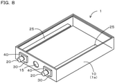
- the case lid 1b is used as the case member 10, and the external terminal 20 is provided to the case lid 1b, however, the case body 1a may be used as the case member 10 in place of the case lid 1b, and the external terminal 20 is provided to the case body 1a.
- the case body 1a is of a flat box shape with an opening on the longitudinal surface side.
- the external terminal 20 is provided on the side wall adjacent to the opening. It is noted that the opening is configured to be sealable by being covered with the case lid that is not illustrated. Also in Modification 3, the same operational effects as those in Working Example 1 are exhibited.
- the terminal-equipped case member 1 which is excellent in airtightness, can be provided.
- a specimen 1p including the base material 11, the external terminal 20, the sealing member 30, the terminal adhesion layer 40, and the base material adhesion layer 50, which are the same configurations as those of the terminal-equipped case member 1 of Working Example 1 was prepared as shown in FIG. 9(a), and FIG. 9(b) that is a cross-section taken along IXb-IXb line of FIG. 9(a) . It is noted that the specimen 1p is provided with only one external terminal 20, and is not provided with the safety valve 15.
- a specimen 1q including the base material 11, the external terminal 20, the sealing member 30, the terminal adhesion layer 40, and the base material adhesion layer 50, which are the same configurations as those of the terminal-equipped case member 1 of Modification 1 was prepared as shown in FIG. 9(c), and FIG. 9(d) that is a cross-section taken along IXd-IXd line of FIG. 9(c) . It is also noted that the specimen 1q was provided with only one external terminal 20, and was not provided with the safety valve 15.
- a specimen 9p configured not to include the terminal adhesion layer 40 and the base material adhesion layer 50 in the above-mentioned specimen 1p was prepared as shown in FIG. 10(a), and FIG. 10(b) that is a cross-section taken along Xb-Xb line of FIG. 10(a) .
- Comparative Test 2 a below-mentioned tensile strength test was performed.
- Test Examples 1 and 2 and Comparative Example 1 were set in the same way as in Comparative Test 1.
- the external terminal 20 and the base material 11 of each specimen 1p, 1q, and 9p in Test Examples 1 and 2, and Comparative Example 1 respectively were chucked and pulled in the axial direction Y of the external terminal 20 at a tensile rate of 25.4 mm/min until the specimen was broken, and the peak load was measured using an electric tensile-testing machine (manufactured by YONEKURA MFG Co., Ltd., Model number: CATY-1005Z).
Landscapes
- Chemical & Material Sciences (AREA)
- Chemical Kinetics & Catalysis (AREA)
- Electrochemistry (AREA)
- General Chemical & Material Sciences (AREA)
- Engineering & Computer Science (AREA)
- Microelectronics & Electronic Packaging (AREA)
- Sealing Battery Cases Or Jackets (AREA)
- Connection Of Batteries Or Terminals (AREA)
- Connector Housings Or Holding Contact Members (AREA)
- Electric Double-Layer Capacitors Or The Like (AREA)
- Casings For Electric Apparatus (AREA)
Description
- The present invention relates to a terminal-equipped case member and to a manufacturing method thereof.
- With regard to a capacitor, a lithium-ion battery etc., which contain an electrolyte thereinside, a terminal-equipped case member equipped with an external terminal for electrically connecting an external device has been heretofore used as its case. In order for such a case member to maintain airtightness inside the case, the gap between the external terminal and the case member is sealed with a sealing member made of resin. And where a case member made of metal is used, the sealing member made of resin acquires also insulation between the case member and the external terminal.
- Meanwhile, an external terminal is usually made of metal, thus satisfactory adhesion cannot be obtained between the sealing member made of resin and the external terminal made of metal in some cases. In case the adhesion is poor, there is a risk that airtightness between the both will decrease, and airtightness inside the case cannot be maintained accordingly. Therefore, according to a configuration disclosed in
JP 5492653 B2 -
CN 102082244 A discloses a battery cover board assembly.JP 2017-97978 A JP 2010-52365 A - Nevertheless, in the configuration disclosed in
JP 5492653 B2 - The present invention has been made in view of such a background, and it is intended to provide a method for manufacturing a terminal-equipped case member that is excellent in airtightness.
- According to the invention a method for manufacturing a terminal-equipped case member according to
claim 1 is provided. - In the terminal-equipped case member produced by the method according to the invention the sealing member and the external terminal are bonded to each other through the terminal adhesion layer, and the second resin material that forms the terminal adhesion layer has a higher adhesion to the external terminal than that of the first resin material. Therefore, in comparison with a case where the terminal adhesion layer is not provided as specified in
claim 1, the adhesion between the external terminal and the sealing member can be increased, so that the airtightness between the external terminal and the base material can be satisfactorily obtained. - As mentioned above, according to the present invention, a method for manufacturing a terminal-equipped case member that is excellent in airtightness can be provided.
-
-
FIG. 1 is a perspective view of an electronic component installed in a terminal-equipped case member, according to Working Example 1. -
FIG. 2 is a cross-sectional view of the terminal-equipped case member taken along II-II line inFIG. 1 . -
FIG. 3 is an enlarged cross-sectional view of the neighborhood of an external terminal inFIG. 2 . -
FIG. 4 is a further enlarged cross-sectional view of the neighborhood of the external terminal inFIG. 3 . -
FIG. 5 is a schematic view showing a manufacturing method of a terminal-equipped case member, according to Working Example 1. -
FIG. 6 is an enlarged cross-sectional view of the neighborhood of an external terminal, according toModification 1. -
FIG. 7 is an enlarged cross-sectional view of the neighborhood of an external terminal, according toModification 2. -
FIG. 8 is a perspective view of a terminal-equipped case member, according toModification 3. -
FIG. 9 shows perspective and cross-sectional views showing configurations of Test Examples 1 and 2 inComparative Tests -
FIG. 10 shows perspective and cross-sectional views showing a configuration of Comparative Example inComparative Tests - The above-mentioned first resin material is an engineering plastic or a super engineering plastic, and the above-mentioned second resin material is an epoxy resin, a polyamide-imide resin, or a polyimide resin. By adopting an engineering plastic or a super engineering plastic as the first resin material, the sealing member can be improved in insulation, heat resistance, chemical resistance, and mechanical characteristics. An epoxy resin, a polyamide-imide resin, or a polyimide resin adopted as the second resin material has high wettability with a heat-melted engineering plastic or super engineering plastic, and is well compatible therewith, thus it has high affinity and compatibility as surface characteristics with respect to the engineering plastic or the super engineering plastic. In addition, because these materials are excellent in heat resistance, heat deterioration due to a heat-melted engineering plastic or super engineering plastic at the time of molding tends not to occur. Therefore, by adopting the first resin material and the second resin material as described above, satisfactory adhesion can be obtained between the terminal adhesion layer and the external terminal made of metal, and between the sealing member and the terminal adhesion layer. Further, because the sealing member and the terminal adhesion layer are both made of resin, satisfactory adhesion can be obtained therebetween. Consequently, the airtightness between the external terminal and the base material can be further improved.
- It is noted that in the present specification, an engineering plastics means a resin material that has a heat-resistant temperature of 100°C or higher, and is more excellent in tensile strength and elastic modulus than those of a general purpose plastic. In addition, a super engineering plastic means a resin material having a heat-resistant temperature of 150°C or higher among engineering plastics.
- The above-mentioned terminal adhesion layer is composed of an electrodeposition coating film. Electrodeposition is a technique for forming a thin polymer film firmly on the surface of an object to be coated, in which the object to be coated of a conductor is immersed in a bath filled with a water-soluble paint for electrodeposition so as to form a water-insoluble coating uniformly on the surface thereof by applying a voltage between the object to be coated and an counter electrode to flow a current, and is subjected to baking and drying. As long as an object to be coated is made of a conductor such as a metal, electrodeposition makes it possible to form a uniform resin thin film on the surface of the object even in the case of a complicated shape. Accordingly, forming the terminal adhesion layer with an electrodeposition coating film allows the terminal adhesion layer to have a uniform film thickness even if an external terminal has a complicated shape. In addition, because the terminal adhesion layer can be formed of a firm resin coating, it will be excellent in heat resistance. As a result, heat deterioration in the terminal adhesion layer due to melting heat at the time of molding the sealing member can be curtailed to thereby achieve further excellent airtightness.
- The thickness of the terminal adhesion layer is preferably within a range of 10-80 µm. In this case, the terminal adhesion layer can have sufficient adhesion to both the external terminal and the sealing member, so that the airtightness between the external terminal and the base material can be further improved.
- It is preferable that the external terminal has a recess or a through hole formed on an outer peripheral surface thereof, part of the terminal adhesion layer penetrates the recess or the through hole, and part of the sealing member is bonded to the part of the terminal adhesion layer that has penetrated the recess or the through hole. In this case, the adhesion of the terminal adhesion layer with respect to the external terminal is improved, so that the airtightness between the external terminal and the base material is further improved.
- Between the base material and the sealing member, there lies a base material adhesion layer formed of a third resin material with a higher adhesion to the base material than that of the first resin material. In this case, the airtightness between the sealing member and the base material is improved having the base material adhesion layer interposed therebetween.
- According to the present invention a method for manufacturing a terminal-equipped case member according to
claim 1 is provided. - According to such a manufacturing method, a terminal-equipped case member that is excellent in airtightness can be manufactured, as described above.
- In the terminal adhesion layer formation step, the terminal adhesion layer is formed on the external terminal by electrodeposition. In this case, the terminal adhesion layer can be formed as a firm thin film by electrodeposition, which tends not to suffer heat deterioration, so that a terminal-equipped case member that is excellent in airtightness can be manufactured. In addition, because such a molding material for the terminal adhesion layer is excellent in throwing power, occurrence of an uncoated part in the area intended to form a terminal adhesion layer can be prevented, and dropping of the molding material hardly occurs, so that a uniform resin coating can be formed. Therefore, control of forming the terminal adhesion layer becomes easy.
- In the sealing step, the sealing member may be formed by filling the gap between the external terminal in the through hole and the base material with the first resin material of an engineering plastic or a super engineering plastic by insert molding. In the past, when insert-molding a metal and an engineering plastic, forming a resin layer on the surface of the metal in advance as an adhesion layer for bonding the both, i.e. application of a so-called primer or a basecoat was rarely performed. However, the first resin material of an engineering plastic or a super engineering plastic can be filled in the gap to form the sealing member by insert molding as described above by forming the terminal adhesion layer by electrodeposition in a firm thin film that tends not to suffer heat deterioration. As a result, the gap can be surely sealed with the sealing member, so that a terminal-equipped case member that is further excellent in airtightness can be manufactured.
- In the terminal adhesion layer formation step, it is preferable that the second resin material of a thermosetting epoxy resin, a polyamide-imide resin, or a polyimide resin is applied to the external terminal by electrodeposition, and is dried in a temperature environment below the curing temperature of the second resin material to thereby form the terminal adhesion layer in a semi-cured state, and in the sealing step, the external terminal is inserted into the through hole to be located inside the through hole such that the terminal adhesion layer thus semi-cured is located inside the through hole, the first resin material of a heat-melted engineering plastic is filled into the gap to cause compatibilization with part of the second resin material, and is heated to the curing temperature of the second resin material or more to thereby completely cure the terminal adhesion layer. In this case, the terminal adhesion layer and the sealing member can be made into a state of being firmly stuck together, so that the airtightness between the base material and the external terminal can be further improved. In addition, between the terminal adhesion layer and the sealing member, a terminal side compatible layer in which both resin materials are compatible with each other is formed. The terminal side compatible layer makes it possible to reduce a stress caused by thermal expansion and contraction difference between the external terminal made of metal and the sealing member formed of resin, so that reduction of the airtightness that will be accompanied with temperature change can be restrained.
- A working example of the above-mentioned terminal-equipped case member is explained below with reference to
FIGS. 1 to 5 . - As shown in
FIG. 1 , a terminal-equippedcase member 1 of Working Example 1 is configured to haveexternal terminals 20 for electrically connecting an external device, which is fixed to acase body 1a for housing anelectronic component 100 or acase member 10 constituting a case lid 1b that is attached to thecase body 1a. - The terminal-equipped
case member 1 includes abase material 11,external terminals 20, and sealingmembers 30 as shown inFIG. 2 . - The
base material 11 is made of metal, and constitutes thecase member 10. - Each
external terminal 20 is inserted into a throughhole 12 formed through thebase material 11. - Each sealing
member 30 is formed of a first resin material, and seals agap 13 between theexternal terminal 20 in the throughhole 12 and thebase material 11. - The
external terminal 20 and the sealingmember 30 are bonded to each other through aterminal adhesion layer 40 formed of a second resin material with a higher adhesion to theexternal terminal 20 than that of the first resin material. - Hereinafter, the terminal-equipped
case member 1 of Working Example 1 is explained in detail. - As shown in
FIG. 1 , thecase body 1a houses anelectronic component 100, and the case lid 1b is attached to the opening of thecase body 1a. In the present example, the case lid 1b serves as thecase member 10, to which the after-mentionedexternal terminal 20 is attached. In the present example, theelectronic component 100 is an electrode body, and an electrolyte is filled inside the case in a state that the opening of thecase body 1a is sealed with the case lid 1b to thereby constitute a secondary battery. - As shown in
FIG. 2 , thebase material 11 made of metal, which forms thecase member 10, is provided with two throughholes 12 and arelief valve 15. In the present example, thebase material 11 is made of an aluminum alloy. And, each through holes 12 has theexternal terminal 20 inserted therethrough. Theexternal terminals 20 are made of metal, which may be copper, aluminum alloys, etc., and copper is used in the present example. In addition, theexternal terminals 20 in the present example are formed in a cylindrical shape. The bottom of eachexternal terminal 20, which is positioned inside thecase body 1a, has acollector 25 welded thereto to be connected to theelectronic component 100. - As shown in
FIG. 3 , theterminal adhesion layer 40 is provided at the central area of the outer surface of theexternal terminal 20 in its axial direction Y, the area including a portion positioned inside the throughhole 12. Theterminal adhesion layer 40 is a resin coating that is formed by electrodeposition. With regard to a resin material for forming the terminal adhesion layer 40 (the second resin material), a resin material with a higher adhesion to theexternal terminal 20 than that of the first resin material that forms the after-mentioned sealingmember 30 is used. For example, as the resin material for forming the terminal adhesion layer 40 (the second resin material), a thermosetting epoxy resin as a cationic electrodeposition coating material, a polyamide-imide resin, or a polyimide resin may be used, and in the present example, the thermosetting epoxy resin is used. An average thickness of theterminal adhesion layer 40 may be set within a range of 10-80 µm, preferably set within a range of 20-50 µm, and is set to 30 µm in the present example. If the average thickness of theterminal adhesion layer 40 is less than 10 µm, fine unevenness on the terminal surface causes uneven coating such that theterminal adhesion layer 40 is made too thin, and/or an uncoated part by which theterminal adhesion layer 40 is not formed, which is not favorable. On the other hand, if the average thickness of theterminal adhesion layer 40 exceeds 80 µm, there is a risk that it may take excessively much time to form the layer, therefore it is considered to be distant. - In the present example, as shown in
FIG. 3 , a basematerial adhesion layer 50 is formed on an area that extends over awall surface 12a of the throughhole 12 in thebase material 11, a certain area on anupper side surface 111 of thebase material 11 near the throughhole 12, and a certain area on aback side surface 112 of thebase material 11 near the throughhole 12,. In the present example, the basematerial adhesion layer 50 is a resin coating formed by electrodeposition as with theterminal adhesion layer 40, and has the same configuration as theterminal adhesion layer 40. - As shown in
FIG. 3 , in the throughhole 12, thegap 13 between thebase material 11 and theexternal terminal 20 is sealed with the sealingmember 30. And theterminal adhesion layer 40 lies between theexternal terminal 20 and the sealingmaterial 30, whereby theexternal terminal 20 and the sealingmember 30 are bonded to each other through theterminal adhesion layer 40. In addition, the basematerial adhesion layer 50 lies between thebase material 11 and the sealingmember 30, whereby thebase material 11 and the sealingmember 30 are bonded to each other. - As a resin material for forming the sealing member 30 (the first resin material), a thermoplastic resin material is preferable in order that the after-mentioned insert molding can be performed, and preferably has a heat-resistant temperature of 150°C or higher in consideration of the circumference of being exposed to high temperature during the insert molding. In addition, from the viewpoint of ensuring the compatibility and adhesiveness between the first resin material and the second resin material, the solubility parameters (SP values) of the both are preferably set to be close to each other. For example, in view of the case where an epoxy resin having an SP value of around 11, a polyamide-imide resin or a polyimide resin having an SP value of around 13.6 is used as the second resin material, a resin material having a solubility parameter (SP value) within a range of 9.5-15 may be used as the first resin material.
- For example, as the first resin material, engineering plastics such as a nylon resin, a polycarbonate resin, etc., and super engineering plastics such as a polyphenylene sulfide (PPS) resin, a polysulfone (PSF) resin, a polyether sulphone (PES) resin, a polyamide-imide (PAI) resin, etc. may be used, and a PPS resin is used in the present example.
- In the present example, as shown in
FIG. 4 , between theterminal adhesion layer 40 and the sealingmember 30, a terminal sidecompatible layer 45 in which both the resin materials are compatible with each other is formed. In addition, between the basematerial adhesion layer 50 and the sealingmember 30, a base material sidecompatible layer 55 in which both the resin materials are compatible with each other is formed. It is noted that the boundaries between the terminal sidecompatible layer 45 and the sealingmember 30, and between the terminal sidecompatible layer 45 and theterminal adhesion layer 40 are actually unclear. Similarly, the boundaries between the base material sidecompatible layer 55 and the sealingmember 30, and between the base material sidecompatible layer 55 and the basematerial adhesion layer 50 are also actually unclear. - Hereinafter, a manufacturing method of the terminal-equipped
case member 1 of the present example is explained. - First, a preparation step S1 shown in
FIG. 5 (a) is performed. In the preparation step S1, thebase material 11 having the throughholes 12 are prepared. The through holes 12 are formed so as to have a larger diameter than that of theexternal terminal 20 so that theexternal terminal 20 can be loosely inserted. - Next, a terminal adhesion layer formation step S2 shown in
FIG.5 (b) is performed. In the terminal adhesion layer formation step S2, theterminal adhesion layer 40 is formed on theexternal terminal 20. In the terminal adhesion layer formation step S2 of the present example, a resin coating composed of a water-solubilized thermosetting epoxy resin is formed by electrodeposition to thereby form theterminal adhesion layer 40. It is noted that in order to form theterminal adhesion layer 40 on theexternal terminal 20 in the area located inside the throughhole 12, and its neighboring area, electrodeposition is performed masking both end regions other than these areas. According to the present example, in the terminal adhesion layer formation step S2, a thermosetting epoxy resin is applied to theexternal terminal 20 by electrodeposition, and is dried in a temperature environment below the curing temperature of the epoxy resin to thereby form theterminal adhesion layer 40 in a semi-cured state. - The electrodeposition in the terminal adhesion layer formation step S2 according to the present example is performed in the following manner. First, washing and degreasing are performed on the surface of the
external terminal 20. Thereafter, theexternal terminal 20 that has been subjected to the washing and degreasing is immersed in a bath for electrodeposition in which a cation type epoxy resin electrodeposition coating material (manufactured by NIPPONPAINT Co., Ltd., Model number: INSULEED3030) with a solid concentration of 20% is filled, and is energized with an applied voltage of 200V for three minutes. Then, theexternal terminal 20 is taken out from the bath, washed with water, and dried in a drying furnace of 130°C for 20 minutes. In this way, theterminal adhesion layer 40, which is composed of an epoxy resin coating in a semi-cured state with an average thickness of 50 µm, can be formed. - Furthermore, in the present example, a base material adhesion layer formation step S3 shown in
FIG.5 (c) is performed. In the base material adhesion layer formation step S3, the basematerial adhesion layer 50 is formed on the wall surface of the throughhole 12 in thebase material 11, anupper side surface 111 of thebase material 11 in the area adjacent to the throughhole 12, and aback side surface 112 of thebase material 11 in the area adjacent to the throughhole 12. The base material adhesion layer formation step S3 is performed by electrodeposition as with the terminal adhesion layer formation step S2. - Thereafter, a sealing step S4 shown in
FIG. 5(d) and FIG. 5(e) is performed. In the sealing step S4, thegap 13 between theexternal terminal 20 in the throughhole 12 and thebase material 11 is sealed with the sealingmember 30 composed of a PPS resin as shown inFIG. 5(e) in a state that theexternal terminal 20 is inserted into the throughhole 12 as shown inFIG. 5(d) . The sealingmember 30 is formed by insert molding. In the present example, theexternal terminal 20 provided with theterminal adhesion layer 40 composed of an epoxy resin coating in a semi-cured state is placed in a mold for insert molding not illustrated in a state of being inserted into the throughhole 12 of thebase material 11, then a PPS resin that has been melted by heating to 330°C is poured into the insert molding mold and filled in thegap 13 as shown inFIG. 5(e) to thereby seal thegap 13 and form the sealingmember 30. Thus, due to the configuration in which theterminal adhesion layer 40 lies between the sealingmember 30 and theexternal terminal 20, the sealingmember 30 and theexternal terminal 20 are bonded to each other through theterminal adhesion layer 40, and due to the configuration in which the basematerial adhesion layer 50 lies between the sealingmember 30 and thebase material 11, the sealingmember 30 and thebase material 11 are bonded to each other through the basematerial adhesion layer 50. Thereafter, thecollector 25 is welded to theexternal terminal 20 to form the terminal-equippedcase member 1 shown inFIG. 2 . - In the present example, by the above-mentioned insert molding, between the
terminal adhesion layer 40 and the sealingmember 30 shown inFIG. 4 , the terminal sidecompatible layer 45 in which both molding materials are compatible with each other is formed, and between the basematerial adhesion layer 50 and the sealingmember 30, the base material sidecompatible layer 55 in which both molding materials are compatible with each other is formed. - Next, operational effects in the terminal-equipped
case member 1 of the present example are explained in detail. - According to the terminal-equipped
case member 1 of the present example, theexternal terminal 20 and the sealingmember 30 are bonded to each other through theterminal adhesion layer 40, and the second resin material that forms theterminal adhesion layer 40 has a higher adhesion to theexternal terminal 20 than that of the first resin material that forms the sealingmember 30. Therefore, in comparison with the case that theterminal adhesion layer 40 is not provided, adhesion between theexternal terminal 20 and the sealingmember 30 can be increased, so that airtightness between theexternal terminal 20 and thebase material 11 can be satisfactorily ensured. - Furthermore, in the present example, an engineering plastic is used as the first resin material that is a molding material for the sealing
member 30, and an epoxy resin is used as the second resin material that is a molding material for theterminal adhesion layer 40. In this way, by adopting an engineering plastic or a super engineering plastic as the first resin material, the sealingmember 30 can be improved in insulation, heat resistance, chemical resistance, and mechanical characteristics. An epoxy resin, a polyamide-imide resin, or a polyimide resin adopted as the second resin material has high wettability with a heat-melted engineering plastic or super engineering plastic, and is well compatible with each other, thus it has high affinity and compatibility with respect to the engineering plastic or the super engineering plastic as surface characteristics. In addition, because these materials are excellent in heat resistance, heat deterioration due to the heat-melted engineering plastic or super engineering plastic tends not to occur during molding. Therefore, by adopting the first resin material and the second resin material as described above, satisfactory adhesion can be obtained between theterminal adhesion layer 40 and theexternal terminal 20 made of metal, and between the sealingmember 30 and theterminal adhesion layer 40. Further, because the sealingmember 30 and theterminal adhesion layer 40 are both made of resin, satisfactory adhesion can be obtained therebetween. Consequently, the airtightness between theexternal terminal 20 and thebase material 11 can be further improved. - Furthermore, in the present example, the
terminal adhesion layer 40 is composed of an electrodeposition coating film. Therefore, even if theexternal terminal 20 might have a complicated shape, theterminal adhesion layer 40 can be made to have a uniform film thickness. In addition, theterminal adhesion layer 40 can be formed of a firm resin coating so as to be excellent in heat resistance. As a result, heat deterioration in theterminal adhesion layer 40 caused by melting heat at the time of molding the sealingmember 30 can be restrained to thereby achieve further excellent airtightness. In particular, when a super engineering plastic is used as the first resin material that is a molding material for the sealingmember 30, because the super engineering plastic has high heat resistance of 150°C or higher, heat deterioration caused by melting heat of the super engineering plastic can be effectively restrained by forming theterminal adhesion layer 40 with an electrodeposition coating film that is excellent in heat resistance. - Furthermore, in the present example, the thickness of the
terminal adhesion layer 40 is set to 30 µm within a range of 10-80 µm. As a result, theterminal adhesion layer 40 can possess sufficient adhesion with respect to both theexternal terminal 20 and the sealingmember 30, so that airtightness between theexternal terminal 20 and thebase material 11 can be further increased. - Furthermore, in the present example, the
base material 11 and the sealingmember 30 are bonded to each other through the basematerial adhesion layer 50 that is formed of the third resin material having a higher adhesion to theexternal terminal 20 than that of the first resin material. As a result, airtightness between the sealingmember 30 and thebase material 11 is increased through the basematerial adhesion layer 50. It is noted that in the present example, the third resin material that forms the basematerial adhesion layer 50 is the same as the molding material (the second resin material) for theterminal adhesion layer 40. Further, in the present example, between the basematerial adhesion layer 50 and the sealingmember 30, the base material sidecompatible layer 55 in which both resin materials are compatible with each other is formed. The base material sidecompatible layer 55 makes it possible to reduce a stress caused by thermal expansion and contraction difference between thebase material 11 made of metal and the sealingmember 30 formed of resin, and thus reduction of the airtightness between the sealingmember 30 and thebase material 11 accompanied with temperature change can be restrained. - The manufacturing method of the terminal-equipped
case member 1 in the present example includes the preparation step S1 of preparing thebase material 11 having the throughhole 12, the terminal adhesion layer formation step S2 of forming theterminal adhesion layer 40 on theexternal terminal 20, and a sealing step S4 of sealing thegap 13 by filling thegap 13 between theexternal terminal 20 in the throughhole 12 and thebase material 11 with the sealingmember 30 in a state that theexternal terminal 20 is inserted into the throughhole 12, so that the sealingmember 30 and theexternal terminal 20 are bonded to each other through theterminal adhesion layer 40. According to such a manufacturing method, the terminal-equippedcase member 1 that is excellent in airtightness as described above can be manufactured. - Furthermore, in the present example, in the terminal adhesion layer formation step S2, the
terminal adhesion layer 40 is formed on theexternal terminal 20 by electrodeposition. Accordingly, theterminal adhesion layer 40 can be formed as a firm thin film by electrodeposition, which makes heat deterioration hardly occur, so that the terminal-equippedcase member 1 that is excellent in airtightness can be manufactured. Furthermore, in electrodeposition, because the throwing power of a molding material for theterminal adhesion layer 40 is satisfactory, occurrence of holiday in the area intended to form aterminal adhesion layer 40 can be prevented, and dropping of the molding material hardly occurs, so that a uniform coating can be formed. As a result, control of forming theterminal adhesion layer 40 becomes easy. - Furthermore, in the present example, in the sealing step S4, the sealing
member 30 is formed by filling the gap between theexternal terminal 20 in the throughhole 12 and thebase material 11 with the first resin material of an engineering plastic or a super engineering plastic by insert molding. Further, in the present example, because theterminal adhesion layer 40 has been formed as a firm thin film by electrodeposition to hardly suffer heat deterioration, the sealingmember 30 can be formed by filling thegap 13 with the first resin material of an engineering plastic or a super engineering plastic by insert molding as described above. As a result, the sealingmember 30 can surely seal thegap 13, so that the terminal-equippedcase member 1, which is further excellent in airtightness, can be manufactured. - Furthermore, in the present example, in the terminal adhesion layer formation step S2, the second resin material of a thermosetting epoxy resin is applied to the
external terminal 20 by electrodeposition, and is dried in a temperature environment below the curing temperature of the second resin material to thereby form theterminal adhesion layer 40 in a semi-cured state. And in the sealing step S4, theexternal terminal 20 is inserted into the throughhole 12 so that theterminal adhesion layer 40 is located inside the through hole12, the first resin material of an engineering plastic is heat-melted and filled into thegap 13 to cause compatibilization with part of the second resin material, and the resin materials thus compatibilized are heated to the curing temperature of the second resin material or more to thereby completely cure theterminal adhesion layer 40. As a result, theterminal adhesion layer 40 and the sealingmember 30 can be made into a state of being firmly stuck together, and thus, the airtightness between the sealingmember 30 and theexternal terminal 20 can be further improved. In addition, between theterminal adhesion layer 40 and the sealingmember 30, the terminal sidecompatible layer 45 in which both resin materials are compatible with each other is formed. The terminal sidecompatible layer 45 makes it possible to reduce a stress caused by thermal expansion and contraction difference between theexternal terminal 20 made of metal and the sealingmember 30 formed of resin, and thus reduction of the airtightness between the sealingmember 30 and theexternal terminal 20 accompanied with temperature change can be restrained. - It is noted that a configuration in which differently from the
external terminal 20 of the present example, theexternal terminal 20 has arecess 21 formed on an outer peripheral surface thereof, apart 46 of theterminal adhesion layer 40 penetrates therecess 21, and apart 35 of the sealingmember 30 is bonded to thepart 46 of theterminal adhesion layer 40 that has penetrated therecess 21 as inModification 1 shown inFIG. 6 , may be adopted. According toModification 1, the adhesion between theterminal adhesion layer 40 and theexternal terminal 20 can be increased to thereby further increase the airtightness between the sealingmember 30 and theexternal terminal 20. - Furthermore, it is noted that a configuration such that differently from the
external terminal 20 of the present example, theexternal terminal 20 has a terminal throughhole 22 formed therethrough, thepart 46 of theterminal adhesion layer 40 penetrates the terminal throughhole 22, and thepart 35 of the sealingmember 30 is bonded to thepart 46 of theterminal adhesion layer 40 that has penetrated the terminal throughhole 22, may be also adopted as shown inModification 2 inFIG. 7(a) and FIG. 7(b) . According also toModification 2, the adhesion between theterminal adhesion layer 40 and theexternal terminal 20 can be increased, and the adhesion between theterminal adhesion layer 40 and the sealingmember 30, so that the airtightness between the sealingmember 30 and theexternal terminal 20 is further increased. - It is noted that in the present example, the case lid 1b is used as the
case member 10, and theexternal terminal 20 is provided to the case lid 1b, however, thecase body 1a may be used as thecase member 10 in place of the case lid 1b, and theexternal terminal 20 is provided to thecase body 1a. In addition, inModification 3, thecase body 1a is of a flat box shape with an opening on the longitudinal surface side. And theexternal terminal 20 is provided on the side wall adjacent to the opening. It is noted that the opening is configured to be sealable by being covered with the case lid that is not illustrated. Also inModification 3, the same operational effects as those in Working Example 1 are exhibited. - As described above, according to the present example, the terminal-equipped
case member 1, which is excellent in airtightness, can be provided. - Next, the following airtightness test was performed as
Comparative Test 1. - First, in preparation for Test Example 1, a
specimen 1p including thebase material 11, theexternal terminal 20, the sealingmember 30, theterminal adhesion layer 40, and the basematerial adhesion layer 50, which are the same configurations as those of the terminal-equippedcase member 1 of Working Example 1 was prepared as shown inFIG. 9(a), and FIG. 9(b) that is a cross-section taken along IXb-IXb line ofFIG. 9(a) . It is noted that thespecimen 1p is provided with only oneexternal terminal 20, and is not provided with thesafety valve 15. - Further, in preparation for Test Example 2, a
specimen 1q including thebase material 11, theexternal terminal 20, the sealingmember 30, theterminal adhesion layer 40, and the basematerial adhesion layer 50, which are the same configurations as those of the terminal-equippedcase member 1 ofModification 1 was prepared as shown inFIG. 9(c), and FIG. 9(d) that is a cross-section taken along IXd-IXd line ofFIG. 9(c) . It is also noted that thespecimen 1q was provided with only oneexternal terminal 20, and was not provided with thesafety valve 15. - Furthermore, in preparation for Comparative Example, a
specimen 9p configured not to include theterminal adhesion layer 40 and the basematerial adhesion layer 50 in the above-mentionedspecimen 1p was prepared as shown inFIG. 10(a), and FIG. 10(b) that is a cross-section taken along Xb-Xb line ofFIG. 10(a) . - As an airtightness test for
Comparative Test 1, Helium Leak Test was adopted and performed in the following manner. First, eachspecimen - Next, as
Comparative Test 2, a below-mentioned tensile strength test was performed. Test Examples 1 and 2, and Comparative Example 1 were set in the same way as inComparative Test 1. In the tensile strength test forComparative Test 2, theexternal terminal 20 and thebase material 11 of eachspecimen external terminal 20 at a tensile rate of 25.4 mm/min until the specimen was broken, and the peak load was measured using an electric tensile-testing machine (manufactured by YONEKURA MFG Co., Ltd., Model number: CATY-1005Z). - Test results of the above-mentioned
Comparative Tests (Table 1) Test Example 1 Test Example 2 Comparative Example Comparative Test 1 (Helium Leak Test) [Pa·m3/sec] 2.4×10⁻⁹ 2.6×10⁻⁹ 1.6×10⁻⁶ Comparative Test 2 (Tensile Strength Test) [MPa] 1.5 8.8 1.6 - As shown in Table 1, it was confirmed that in
Comparative Test 1, the He leakage amounts in Test Examples 1 and 2 are significantly smaller than that in Comparative Example. And it was confirmed that inComparative Test 2, Test Example 1 has a tensile strength equivalent to that of Comparative Example, and Test Example 2 has a tensile strength significantly larger than that of Comparative Example.
Claims (3)
- A method for manufacturing a terminal-equipped case member (1) having an external terminal (20) for electrically connecting an external device, which is fixed to a case body (1a) for housing an electronic component (100) or a case member (10) constituting a case lid (16) that is attached to the case body (1a), the terminal-equipped case member (1) comprising:a base material (11) made of metal that forms the case member (1);the external terminal (20) made of metal that is inserted into a through hole (12) formed through the base material (11); anda sealing member (30) formed of a first resin material that seals a gap between the external terminal (20) in the through hole (12) and the base material (11), whereinthe external terminal (20) and the sealing member (30) are bonded to each other through a terminal adhesion layer (40) formed of a second resin material with a higher adhesion to the external terminal (20) than that of the first resin material,the first resin material is an engineering plastic or a super engineering plastic, andthe second resin material is an epoxy resin, a polyamide-imide resin, or a polyimide resin, the method comprising:a preparation step of preparing the base material (11) having the through hole (12);a terminal adhesion layer formation step of forming the terminal adhesion layer (40) on the external terminal (20); anda sealing step of sealing the gap by filling the gap between the external terminal (20) in the through hole (12) and the base material (11) with the first resin material in a state that the external terminal (20) is inserted into the through hole (12) to form the sealing member (30) so that the external terminal (20) and the sealing member (30) are bonded to each other through the terminal adhesion layer (40),wherein in the terminal adhesion layer formation step, the terminal adhesion layer (40) is formed on the external terminal (20) by electrodeposition.
- The method for manufacturing the terminal-equipped case member according to claim 1, wherein in the sealing step, the sealing member (30) is formed by filling the gap between the external terminal (20) in the through hole (12) and the base material (11) with the first resin material of an engineering plastic or a super engineering plastic by insert molding.
- The method for manufacturing the terminal-equipped case member according to claim 1 or 2, wherein in the terminal adhesion layer formation step, the second resin material of a thermosetting epoxy resin, a polyamide-imide resin, or a polyimide resin is applied to the external terminal (20) by electrodeposition, and is dried in a temperature environment below the curing temperature of the second resin material to thereby form the terminal adhesion layer (40) in a semi-cured state, and
in the sealing step, the external terminal (20) is inserted into the through hole (12) to be located inside the through hole (12), the first resin material of an engineering plastic or a super engineering plastic is heat-melted and filled into the gap to cause compatibilization with part of the second resin material, and the resin materials thus compatibilized are heated to the curing temperature of the second resin material or more to thereby completely cure the terminal adhesion layer (40).
Applications Claiming Priority (2)
| Application Number | Priority Date | Filing Date | Title |
|---|---|---|---|
| JP2018219791A JP6636121B1 (en) | 2018-11-23 | 2018-11-23 | Case member with terminal and method of manufacturing the same |
| PCT/JP2019/044311 WO2020105506A1 (en) | 2018-11-23 | 2019-11-12 | Case member with terminals, and method for manufacturing same |
Publications (3)
| Publication Number | Publication Date |
|---|---|
| EP3731298A1 EP3731298A1 (en) | 2020-10-28 |
| EP3731298A4 EP3731298A4 (en) | 2021-06-09 |
| EP3731298B1 true EP3731298B1 (en) | 2022-03-16 |
Family
ID=69183684
Family Applications (1)
| Application Number | Title | Priority Date | Filing Date |
|---|---|---|---|
| EP19887423.2A Active EP3731298B1 (en) | 2018-11-23 | 2019-11-12 | Case member with terminals, and method for manufacturing same |
Country Status (6)
| Country | Link |
|---|---|
| US (1) | US11664551B2 (en) |
| EP (1) | EP3731298B1 (en) |
| JP (1) | JP6636121B1 (en) |
| KR (1) | KR102222550B1 (en) |
| CN (1) | CN111656556B (en) |
| WO (1) | WO2020105506A1 (en) |
Families Citing this family (15)
| Publication number | Priority date | Publication date | Assignee | Title |
|---|---|---|---|---|
| JP7527793B2 (en) * | 2020-01-23 | 2024-08-05 | 日本パーカライジング株式会社 | Lithium ion battery can lid and lithium ion battery can body equipped with said lithium ion battery can lid |
| JP6923700B1 (en) * | 2020-03-25 | 2021-08-25 | 昭和電工株式会社 | Electrochemical elements and methods for manufacturing electrochemical elements |
| DE102021203995A1 (en) * | 2021-04-21 | 2022-10-27 | Elringklinger Ag | Electrochemical cell and method of making an electrochemical cell |
| JP7745876B2 (en) * | 2021-12-27 | 2025-09-30 | 株式会社大北製作所 | metal resin joint |
| JP2023163595A (en) * | 2022-04-28 | 2023-11-10 | プライムアースEvエナジー株式会社 | secondary battery |
| CN114667022B (en) * | 2022-05-24 | 2022-08-23 | 苏州百孝医疗科技有限公司 | Packaging process of electronic product, electronic product and continuous analyte monitoring system |
| JP7485227B1 (en) | 2022-08-10 | 2024-05-16 | 株式会社レゾナック | Method for manufacturing joined body, joined body, and electric/electronic component |
| JP2024040550A (en) * | 2022-09-13 | 2024-03-26 | 日本ケミコン株式会社 | Electricity storage device, terminal parts, and method for manufacturing electricity storage device |
| JP7485005B1 (en) | 2022-12-19 | 2024-05-16 | 株式会社レゾナック | Method for manufacturing joined body, joined body, and electric/electronic component |
| AT526993B1 (en) * | 2023-02-16 | 2025-07-15 | Avl List Gmbh | Battery storage device |
| JP7485170B1 (en) | 2023-06-15 | 2024-05-16 | 株式会社レゾナック | Method for manufacturing joined body and electric/electronic component |
| JP7475090B1 (en) | 2023-07-19 | 2024-04-26 | 株式会社大北製作所 | Manufacturing method of the joint body |
| DE102023132844B3 (en) * | 2023-11-24 | 2025-04-24 | Carl Freudenberg Kg | Cover assembly for a battery cell |
| JP2025153760A (en) * | 2024-03-29 | 2025-10-10 | 日本軽金属株式会社 | Lid and manufacturing method thereof |
| KR102892841B1 (en) * | 2024-04-26 | 2025-12-02 | 동원시스템즈 주식회사 | Cell pouch for secondary battery and its manufacturing method |
Family Cites Families (19)
| Publication number | Priority date | Publication date | Assignee | Title |
|---|---|---|---|---|
| US5182178A (en) * | 1992-05-21 | 1993-01-26 | Gates Energy Products, Inc. | Suppression of electrolyte leakage from the terminal of a lead-acid battery |
| JP3260349B2 (en) * | 2000-06-05 | 2002-02-25 | 松下電器産業株式会社 | Sealant for electrochemical device and electrochemical device using the same |
| JP5085950B2 (en) * | 2006-02-07 | 2012-11-28 | 三洋電機株式会社 | Battery case, battery and non-aqueous electrolyte secondary battery |
| JP5040142B2 (en) * | 2006-03-31 | 2012-10-03 | 株式会社デンソー | Battery case lid |
| JP2010052365A (en) * | 2008-08-29 | 2010-03-11 | Toyota Motor Corp | Insert resin molding product and method for manufacturing the same |
| CN102082244B (en) * | 2009-11-28 | 2016-06-15 | 上海比亚迪有限公司 | Battery cover assembly, its preparation method, single battery and battery pack |
| KR101073010B1 (en) * | 2010-04-19 | 2011-10-12 | 삼성에스디아이 주식회사 | Secondary battery |
| JP5492653B2 (en) | 2010-05-07 | 2014-05-14 | 日立ビークルエナジー株式会社 | Secondary battery |
| KR20130099975A (en) * | 2010-09-21 | 2013-09-06 | 신코베덴키 가부시키가이샤 | Nonaqueous Electrolyte Secondary Battery |
| KR101494811B1 (en) * | 2010-11-11 | 2015-02-23 | 후지모리 고교 가부시키가이샤 | Process for producing sealing film, and sealing film |
| JP2012248487A (en) * | 2011-05-31 | 2012-12-13 | Mitsubishi Heavy Ind Ltd | Electrical appliance |
| KR101851485B1 (en) * | 2014-03-19 | 2018-04-23 | 도판 인사츠 가부시키가이샤 | Secondary battery |
| WO2015198526A1 (en) * | 2014-06-26 | 2015-12-30 | パナソニックIpマネジメント株式会社 | Rolled-type battery |
| JP2017097978A (en) * | 2015-11-19 | 2017-06-01 | 東レ・デュポン株式会社 | Opening-seal plate for closed type power storage device, method for manufacturing the same, and closed type power storage device |
| JP6817791B2 (en) * | 2016-11-15 | 2021-01-20 | 株式会社東芝 | battery |
| JP2018139190A (en) * | 2017-02-24 | 2018-09-06 | リチウム エナジー アンド パワー ゲゼルシャフト ミット ベシュレンクテル ハフッング ウント コンパニー コマンディトゲゼルシャフトLithium Energy and Power GmbH & Co. KG | Power storage element |
| JP7171183B2 (en) * | 2017-12-19 | 2022-11-15 | 三洋電機株式会社 | Secondary battery and assembled battery using the same |
| CN208014758U (en) * | 2018-01-30 | 2018-10-26 | 中澳科创(深圳)新材料有限公司 | A kind of glass seal packs of cover plate of power battery and pole |
| KR102766735B1 (en) * | 2018-02-07 | 2025-02-12 | 다이니폰 인사츠 가부시키가이샤 | Battery packaging material, manufacturing method thereof, and battery |
-
2018
- 2018-11-23 JP JP2018219791A patent/JP6636121B1/en active Active
-
2019
- 2019-11-12 KR KR1020207022348A patent/KR102222550B1/en active Active
- 2019-11-12 WO PCT/JP2019/044311 patent/WO2020105506A1/en not_active Ceased
- 2019-11-12 EP EP19887423.2A patent/EP3731298B1/en active Active
- 2019-11-12 CN CN201980009925.3A patent/CN111656556B/en active Active
- 2019-11-12 US US16/634,729 patent/US11664551B2/en active Active
Also Published As
| Publication number | Publication date |
|---|---|
| CN111656556B (en) | 2021-10-22 |
| JP6636121B1 (en) | 2020-01-29 |
| EP3731298A1 (en) | 2020-10-28 |
| US20220278398A1 (en) | 2022-09-01 |
| CN111656556A (en) | 2020-09-11 |
| KR20200096674A (en) | 2020-08-12 |
| US11664551B2 (en) | 2023-05-30 |
| KR102222550B1 (en) | 2021-03-05 |
| EP3731298A4 (en) | 2021-06-09 |
| WO2020105506A1 (en) | 2020-05-28 |
| JP2020088137A (en) | 2020-06-04 |
Similar Documents
| Publication | Publication Date | Title |
|---|---|---|
| US11664551B2 (en) | Terminal-equipped case member and manufacturing method thereof | |
| US5707407A (en) | Method of forming chip-formed solid electrolytic capacitor without an anode lead projecting from anode member | |
| US9293263B2 (en) | Solid electrolytic capacitor | |
| US8432665B2 (en) | Solid electrolytic capacitor and manufacturing method thereof | |
| CN2914267Y (en) | Sealing terminal assembly | |
| CN111801813B (en) | battery terminals | |
| JP6110964B2 (en) | Solid electrolytic capacitor with improved ESR stability | |
| CN105098439B (en) | Metal nano is molded air-tight electric connector and its manufacturing process | |
| US12154726B2 (en) | Solid electrolytic capacitor element and solid electrolytic capacitor | |
| CN101192473A (en) | Surface-mount type electrolytic capacitor and method of producing the same | |
| JP2024545094A (en) | Sealed static bipolar battery and method for manufacturing and assembling same | |
| JP7745876B2 (en) | metal resin joint | |
| EP3246929B1 (en) | Feedthrough seal apparatus | |
| JPH01151228A (en) | Manufacture of solid electrolytic capacitor | |
| JP2024162621A (en) | Terminal case and its manufacturing method | |
| CN101300652A (en) | Solid electrolytic capacitor and manufacturing method thereof | |
| CN204118173U (en) | A kind of battery terminal assembly | |
| WO2022030210A1 (en) | Capacitor and manufacturing method therefor | |
| JP2010087308A (en) | Solid electrolytic capacitor | |
| JP7475090B1 (en) | Manufacturing method of the joint body | |
| JP2784124B2 (en) | Liquid insulation coating method for lead wire | |
| JPH02285625A (en) | Manufacture of solid electrolytic condenser | |
| JP7354732B2 (en) | Capacitor and its manufacturing method | |
| JPH03215924A (en) | Manufacture of solid electrolytic capacitor | |
| JPH0624178B2 (en) | Method for manufacturing solid electrolytic capacitor |
Legal Events
| Date | Code | Title | Description |
|---|---|---|---|
| STAA | Information on the status of an ep patent application or granted ep patent |
Free format text: STATUS: THE INTERNATIONAL PUBLICATION HAS BEEN MADE |
|
| PUAI | Public reference made under article 153(3) epc to a published international application that has entered the european phase |
Free format text: ORIGINAL CODE: 0009012 |
|
| STAA | Information on the status of an ep patent application or granted ep patent |
Free format text: STATUS: REQUEST FOR EXAMINATION WAS MADE |
|
| 17P | Request for examination filed |
Effective date: 20200721 |
|
| AK | Designated contracting states |
Kind code of ref document: A1 Designated state(s): AL AT BE BG CH CY CZ DE DK EE ES FI FR GB GR HR HU IE IS IT LI LT LU LV MC MK MT NL NO PL PT RO RS SE SI SK SM TR |
|
| AX | Request for extension of the european patent |
Extension state: BA ME |
|
| REG | Reference to a national code |
Ref country code: DE Ref legal event code: R079 Ref document number: 602019012684 Country of ref document: DE Free format text: PREVIOUS MAIN CLASS: H01M0002060000 Ipc: H01M0050147000 |
|
| A4 | Supplementary search report drawn up and despatched |
Effective date: 20210507 |
|
| RIC1 | Information provided on ipc code assigned before grant |
Ipc: H01M 50/147 20210101AFI20210430BHEP Ipc: H01M 50/172 20210101ALI20210430BHEP Ipc: H01M 50/193 20210101ALI20210430BHEP Ipc: H01M 50/543 20210101ALI20210430BHEP |
|
| GRAP | Despatch of communication of intention to grant a patent |
Free format text: ORIGINAL CODE: EPIDOSNIGR1 |
|
| STAA | Information on the status of an ep patent application or granted ep patent |
Free format text: STATUS: GRANT OF PATENT IS INTENDED |
|
| DAV | Request for validation of the european patent (deleted) | ||
| DAX | Request for extension of the european patent (deleted) | ||
| INTG | Intention to grant announced |
Effective date: 20211221 |
|
| GRAS | Grant fee paid |
Free format text: ORIGINAL CODE: EPIDOSNIGR3 |
|
| GRAA | (expected) grant |
Free format text: ORIGINAL CODE: 0009210 |
|
| STAA | Information on the status of an ep patent application or granted ep patent |
Free format text: STATUS: THE PATENT HAS BEEN GRANTED |
|
| AK | Designated contracting states |
Kind code of ref document: B1 Designated state(s): AL AT BE BG CH CY CZ DE DK EE ES FI FR GB GR HR HU IE IS IT LI LT LU LV MC MK MT NL NO PL PT RO RS SE SI SK SM TR |
|
| REG | Reference to a national code |
Ref country code: GB Ref legal event code: FG4D |
|
| REG | Reference to a national code |
Ref country code: CH Ref legal event code: EP |
|
| REG | Reference to a national code |
Ref country code: DE Ref legal event code: R096 Ref document number: 602019012684 Country of ref document: DE |
|
| REG | Reference to a national code |
Ref country code: IE Ref legal event code: FG4D |
|
| REG | Reference to a national code |
Ref country code: AT Ref legal event code: REF Ref document number: 1476531 Country of ref document: AT Kind code of ref document: T Effective date: 20220415 |
|
| REG | Reference to a national code |
Ref country code: NO Ref legal event code: T2 Effective date: 20220316 |
|
| REG | Reference to a national code |
Ref country code: LT Ref legal event code: MG9D |
|
| REG | Reference to a national code |
Ref country code: NL Ref legal event code: MP Effective date: 20220316 |
|
| PG25 | Lapsed in a contracting state [announced via postgrant information from national office to epo] |
Ref country code: SE Free format text: LAPSE BECAUSE OF FAILURE TO SUBMIT A TRANSLATION OF THE DESCRIPTION OR TO PAY THE FEE WITHIN THE PRESCRIBED TIME-LIMIT Effective date: 20220316 Ref country code: RS Free format text: LAPSE BECAUSE OF FAILURE TO SUBMIT A TRANSLATION OF THE DESCRIPTION OR TO PAY THE FEE WITHIN THE PRESCRIBED TIME-LIMIT Effective date: 20220316 Ref country code: LT Free format text: LAPSE BECAUSE OF FAILURE TO SUBMIT A TRANSLATION OF THE DESCRIPTION OR TO PAY THE FEE WITHIN THE PRESCRIBED TIME-LIMIT Effective date: 20220316 Ref country code: HR Free format text: LAPSE BECAUSE OF FAILURE TO SUBMIT A TRANSLATION OF THE DESCRIPTION OR TO PAY THE FEE WITHIN THE PRESCRIBED TIME-LIMIT Effective date: 20220316 Ref country code: BG Free format text: LAPSE BECAUSE OF FAILURE TO SUBMIT A TRANSLATION OF THE DESCRIPTION OR TO PAY THE FEE WITHIN THE PRESCRIBED TIME-LIMIT Effective date: 20220616 |
|
| REG | Reference to a national code |
Ref country code: AT Ref legal event code: MK05 Ref document number: 1476531 Country of ref document: AT Kind code of ref document: T Effective date: 20220316 |
|
| PG25 | Lapsed in a contracting state [announced via postgrant information from national office to epo] |
Ref country code: LV Free format text: LAPSE BECAUSE OF FAILURE TO SUBMIT A TRANSLATION OF THE DESCRIPTION OR TO PAY THE FEE WITHIN THE PRESCRIBED TIME-LIMIT Effective date: 20220316 Ref country code: GR Free format text: LAPSE BECAUSE OF FAILURE TO SUBMIT A TRANSLATION OF THE DESCRIPTION OR TO PAY THE FEE WITHIN THE PRESCRIBED TIME-LIMIT Effective date: 20220617 Ref country code: FI Free format text: LAPSE BECAUSE OF FAILURE TO SUBMIT A TRANSLATION OF THE DESCRIPTION OR TO PAY THE FEE WITHIN THE PRESCRIBED TIME-LIMIT Effective date: 20220316 |
|
| PG25 | Lapsed in a contracting state [announced via postgrant information from national office to epo] |
Ref country code: NL Free format text: LAPSE BECAUSE OF FAILURE TO SUBMIT A TRANSLATION OF THE DESCRIPTION OR TO PAY THE FEE WITHIN THE PRESCRIBED TIME-LIMIT Effective date: 20220316 |
|
| PG25 | Lapsed in a contracting state [announced via postgrant information from national office to epo] |
Ref country code: SM Free format text: LAPSE BECAUSE OF FAILURE TO SUBMIT A TRANSLATION OF THE DESCRIPTION OR TO PAY THE FEE WITHIN THE PRESCRIBED TIME-LIMIT Effective date: 20220316 Ref country code: SK Free format text: LAPSE BECAUSE OF FAILURE TO SUBMIT A TRANSLATION OF THE DESCRIPTION OR TO PAY THE FEE WITHIN THE PRESCRIBED TIME-LIMIT Effective date: 20220316 Ref country code: RO Free format text: LAPSE BECAUSE OF FAILURE TO SUBMIT A TRANSLATION OF THE DESCRIPTION OR TO PAY THE FEE WITHIN THE PRESCRIBED TIME-LIMIT Effective date: 20220316 Ref country code: PT Free format text: LAPSE BECAUSE OF FAILURE TO SUBMIT A TRANSLATION OF THE DESCRIPTION OR TO PAY THE FEE WITHIN THE PRESCRIBED TIME-LIMIT Effective date: 20220718 Ref country code: ES Free format text: LAPSE BECAUSE OF FAILURE TO SUBMIT A TRANSLATION OF THE DESCRIPTION OR TO PAY THE FEE WITHIN THE PRESCRIBED TIME-LIMIT Effective date: 20220316 Ref country code: EE Free format text: LAPSE BECAUSE OF FAILURE TO SUBMIT A TRANSLATION OF THE DESCRIPTION OR TO PAY THE FEE WITHIN THE PRESCRIBED TIME-LIMIT Effective date: 20220316 Ref country code: CZ Free format text: LAPSE BECAUSE OF FAILURE TO SUBMIT A TRANSLATION OF THE DESCRIPTION OR TO PAY THE FEE WITHIN THE PRESCRIBED TIME-LIMIT Effective date: 20220316 Ref country code: AT Free format text: LAPSE BECAUSE OF FAILURE TO SUBMIT A TRANSLATION OF THE DESCRIPTION OR TO PAY THE FEE WITHIN THE PRESCRIBED TIME-LIMIT Effective date: 20220316 |
|
| PG25 | Lapsed in a contracting state [announced via postgrant information from national office to epo] |
Ref country code: PL Free format text: LAPSE BECAUSE OF FAILURE TO SUBMIT A TRANSLATION OF THE DESCRIPTION OR TO PAY THE FEE WITHIN THE PRESCRIBED TIME-LIMIT Effective date: 20220316 Ref country code: IS Free format text: LAPSE BECAUSE OF FAILURE TO SUBMIT A TRANSLATION OF THE DESCRIPTION OR TO PAY THE FEE WITHIN THE PRESCRIBED TIME-LIMIT Effective date: 20220716 Ref country code: AL Free format text: LAPSE BECAUSE OF FAILURE TO SUBMIT A TRANSLATION OF THE DESCRIPTION OR TO PAY THE FEE WITHIN THE PRESCRIBED TIME-LIMIT Effective date: 20220316 |
|
| REG | Reference to a national code |
Ref country code: DE Ref legal event code: R097 Ref document number: 602019012684 Country of ref document: DE |
|
| PLBE | No opposition filed within time limit |
Free format text: ORIGINAL CODE: 0009261 |
|
| STAA | Information on the status of an ep patent application or granted ep patent |
Free format text: STATUS: NO OPPOSITION FILED WITHIN TIME LIMIT |
|
| PG25 | Lapsed in a contracting state [announced via postgrant information from national office to epo] |
Ref country code: DK Free format text: LAPSE BECAUSE OF FAILURE TO SUBMIT A TRANSLATION OF THE DESCRIPTION OR TO PAY THE FEE WITHIN THE PRESCRIBED TIME-LIMIT Effective date: 20220316 |
|
| 26N | No opposition filed |
Effective date: 20221219 |
|
| PG25 | Lapsed in a contracting state [announced via postgrant information from national office to epo] |
Ref country code: SI Free format text: LAPSE BECAUSE OF FAILURE TO SUBMIT A TRANSLATION OF THE DESCRIPTION OR TO PAY THE FEE WITHIN THE PRESCRIBED TIME-LIMIT Effective date: 20220316 |
|
| PG25 | Lapsed in a contracting state [announced via postgrant information from national office to epo] |
Ref country code: MC Free format text: LAPSE BECAUSE OF FAILURE TO SUBMIT A TRANSLATION OF THE DESCRIPTION OR TO PAY THE FEE WITHIN THE PRESCRIBED TIME-LIMIT Effective date: 20220316 |
|
| REG | Reference to a national code |
Ref country code: CH Ref legal event code: PL |
|
| REG | Reference to a national code |
Ref country code: BE Ref legal event code: MM Effective date: 20221130 |
|
| PG25 | Lapsed in a contracting state [announced via postgrant information from national office to epo] |
Ref country code: LI Free format text: LAPSE BECAUSE OF NON-PAYMENT OF DUE FEES Effective date: 20221130 Ref country code: IT Free format text: LAPSE BECAUSE OF FAILURE TO SUBMIT A TRANSLATION OF THE DESCRIPTION OR TO PAY THE FEE WITHIN THE PRESCRIBED TIME-LIMIT Effective date: 20220316 Ref country code: CH Free format text: LAPSE BECAUSE OF NON-PAYMENT OF DUE FEES Effective date: 20221130 |
|
| PG25 | Lapsed in a contracting state [announced via postgrant information from national office to epo] |
Ref country code: LU Free format text: LAPSE BECAUSE OF NON-PAYMENT OF DUE FEES Effective date: 20221112 |
|
| PG25 | Lapsed in a contracting state [announced via postgrant information from national office to epo] |
Ref country code: IE Free format text: LAPSE BECAUSE OF NON-PAYMENT OF DUE FEES Effective date: 20221112 |
|
| PG25 | Lapsed in a contracting state [announced via postgrant information from national office to epo] |
Ref country code: BE Free format text: LAPSE BECAUSE OF NON-PAYMENT OF DUE FEES Effective date: 20221130 |
|
| PG25 | Lapsed in a contracting state [announced via postgrant information from national office to epo] |
Ref country code: CY Free format text: LAPSE BECAUSE OF FAILURE TO SUBMIT A TRANSLATION OF THE DESCRIPTION OR TO PAY THE FEE WITHIN THE PRESCRIBED TIME-LIMIT Effective date: 20220316 |
|
| PG25 | Lapsed in a contracting state [announced via postgrant information from national office to epo] |
Ref country code: MK Free format text: LAPSE BECAUSE OF FAILURE TO SUBMIT A TRANSLATION OF THE DESCRIPTION OR TO PAY THE FEE WITHIN THE PRESCRIBED TIME-LIMIT Effective date: 20220316 Ref country code: HU Free format text: LAPSE BECAUSE OF FAILURE TO SUBMIT A TRANSLATION OF THE DESCRIPTION OR TO PAY THE FEE WITHIN THE PRESCRIBED TIME-LIMIT; INVALID AB INITIO Effective date: 20191112 |
|
| PG25 | Lapsed in a contracting state [announced via postgrant information from national office to epo] |
Ref country code: MT Free format text: LAPSE BECAUSE OF FAILURE TO SUBMIT A TRANSLATION OF THE DESCRIPTION OR TO PAY THE FEE WITHIN THE PRESCRIBED TIME-LIMIT Effective date: 20220316 |
|
| PG25 | Lapsed in a contracting state [announced via postgrant information from national office to epo] |
Ref country code: TR Free format text: LAPSE BECAUSE OF FAILURE TO SUBMIT A TRANSLATION OF THE DESCRIPTION OR TO PAY THE FEE WITHIN THE PRESCRIBED TIME-LIMIT Effective date: 20220316 |
|
| PGFP | Annual fee paid to national office [announced via postgrant information from national office to epo] |
Ref country code: DE Payment date: 20251118 Year of fee payment: 7 |
|
| PGFP | Annual fee paid to national office [announced via postgrant information from national office to epo] |
Ref country code: GB Payment date: 20251119 Year of fee payment: 7 |
|
| PGFP | Annual fee paid to national office [announced via postgrant information from national office to epo] |
Ref country code: NO Payment date: 20251124 Year of fee payment: 7 |
|
| PGFP | Annual fee paid to national office [announced via postgrant information from national office to epo] |
Ref country code: FR Payment date: 20251120 Year of fee payment: 7 |