EP3730740A1 - Conduit pour pièce de stator pour turbomachine - Google Patents
Conduit pour pièce de stator pour turbomachine Download PDFInfo
- Publication number
- EP3730740A1 EP3730740A1 EP20169774.5A EP20169774A EP3730740A1 EP 3730740 A1 EP3730740 A1 EP 3730740A1 EP 20169774 A EP20169774 A EP 20169774A EP 3730740 A1 EP3730740 A1 EP 3730740A1
- Authority
- EP
- European Patent Office
- Prior art keywords
- internal
- equal
- thickness
- duct
- ridge
- Prior art date
- Legal status (The legal status is an assumption and is not a legal conclusion. Google has not performed a legal analysis and makes no representation as to the accuracy of the status listed.)
- Granted
Links
Images



Classifications
-
- F—MECHANICAL ENGINEERING; LIGHTING; HEATING; WEAPONS; BLASTING
- F01—MACHINES OR ENGINES IN GENERAL; ENGINE PLANTS IN GENERAL; STEAM ENGINES
- F01D—NON-POSITIVE DISPLACEMENT MACHINES OR ENGINES, e.g. STEAM TURBINES
- F01D5/00—Blades; Blade-carrying members; Heating, heat-insulating, cooling or antivibration means on the blades or the members
- F01D5/12—Blades
- F01D5/14—Form or construction
- F01D5/147—Construction, i.e. structural features, e.g. of weight-saving hollow blades
-
- B—PERFORMING OPERATIONS; TRANSPORTING
- B22—CASTING; POWDER METALLURGY
- B22F—WORKING METALLIC POWDER; MANUFACTURE OF ARTICLES FROM METALLIC POWDER; MAKING METALLIC POWDER; APPARATUS OR DEVICES SPECIALLY ADAPTED FOR METALLIC POWDER
- B22F10/00—Additive manufacturing of workpieces or articles from metallic powder
- B22F10/20—Direct sintering or melting
- B22F10/28—Powder bed fusion, e.g. selective laser melting [SLM] or electron beam melting [EBM]
-
- B—PERFORMING OPERATIONS; TRANSPORTING
- B22—CASTING; POWDER METALLURGY
- B22F—WORKING METALLIC POWDER; MANUFACTURE OF ARTICLES FROM METALLIC POWDER; MAKING METALLIC POWDER; APPARATUS OR DEVICES SPECIALLY ADAPTED FOR METALLIC POWDER
- B22F10/00—Additive manufacturing of workpieces or articles from metallic powder
- B22F10/30—Process control
- B22F10/38—Process control to achieve specific product aspects, e.g. surface smoothness, density, porosity or hollow structures
- B22F10/385—Overhang structures
-
- B—PERFORMING OPERATIONS; TRANSPORTING
- B22—CASTING; POWDER METALLURGY
- B22F—WORKING METALLIC POWDER; MANUFACTURE OF ARTICLES FROM METALLIC POWDER; MAKING METALLIC POWDER; APPARATUS OR DEVICES SPECIALLY ADAPTED FOR METALLIC POWDER
- B22F5/00—Manufacture of workpieces or articles from metallic powder characterised by the special shape of the product
- B22F5/009—Manufacture of workpieces or articles from metallic powder characterised by the special shape of the product of turbine components other than turbine blades
-
- B—PERFORMING OPERATIONS; TRANSPORTING
- B22—CASTING; POWDER METALLURGY
- B22F—WORKING METALLIC POWDER; MANUFACTURE OF ARTICLES FROM METALLIC POWDER; MAKING METALLIC POWDER; APPARATUS OR DEVICES SPECIALLY ADAPTED FOR METALLIC POWDER
- B22F5/00—Manufacture of workpieces or articles from metallic powder characterised by the special shape of the product
- B22F5/10—Manufacture of workpieces or articles from metallic powder characterised by the special shape of the product of articles with cavities or holes, not otherwise provided for in the preceding subgroups
- B22F5/106—Tube or ring forms
-
- B—PERFORMING OPERATIONS; TRANSPORTING
- B33—ADDITIVE MANUFACTURING TECHNOLOGY
- B33Y—ADDITIVE MANUFACTURING, i.e. MANUFACTURING OF THREE-DIMENSIONAL [3D] OBJECTS BY ADDITIVE DEPOSITION, ADDITIVE AGGLOMERATION OR ADDITIVE LAYERING, e.g. BY 3D PRINTING, STEREOLITHOGRAPHY OR SELECTIVE LASER SINTERING
- B33Y80/00—Products made by additive manufacturing
-
- F—MECHANICAL ENGINEERING; LIGHTING; HEATING; WEAPONS; BLASTING
- F01—MACHINES OR ENGINES IN GENERAL; ENGINE PLANTS IN GENERAL; STEAM ENGINES
- F01D—NON-POSITIVE DISPLACEMENT MACHINES OR ENGINES, e.g. STEAM TURBINES
- F01D9/00—Stators
- F01D9/02—Nozzles; Nozzle boxes; Stator blades; Guide conduits, e.g. individual nozzles
-
- F—MECHANICAL ENGINEERING; LIGHTING; HEATING; WEAPONS; BLASTING
- F01—MACHINES OR ENGINES IN GENERAL; ENGINE PLANTS IN GENERAL; STEAM ENGINES
- F01D—NON-POSITIVE DISPLACEMENT MACHINES OR ENGINES, e.g. STEAM TURBINES
- F01D9/00—Stators
- F01D9/02—Nozzles; Nozzle boxes; Stator blades; Guide conduits, e.g. individual nozzles
- F01D9/026—Scrolls for radial machines or engines
-
- F—MECHANICAL ENGINEERING; LIGHTING; HEATING; WEAPONS; BLASTING
- F01—MACHINES OR ENGINES IN GENERAL; ENGINE PLANTS IN GENERAL; STEAM ENGINES
- F01D—NON-POSITIVE DISPLACEMENT MACHINES OR ENGINES, e.g. STEAM TURBINES
- F01D9/00—Stators
- F01D9/06—Fluid supply conduits to nozzles or the like
- F01D9/065—Fluid supply or removal conduits traversing the working fluid flow, e.g. for lubrication-, cooling-, or sealing fluids
-
- F—MECHANICAL ENGINEERING; LIGHTING; HEATING; WEAPONS; BLASTING
- F04—POSITIVE - DISPLACEMENT MACHINES FOR LIQUIDS; PUMPS FOR LIQUIDS OR ELASTIC FLUIDS
- F04D—NON-POSITIVE-DISPLACEMENT PUMPS
- F04D29/00—Details, component parts, or accessories
- F04D29/02—Selection of particular materials
- F04D29/026—Selection of particular materials especially adapted for liquid pumps
-
- F—MECHANICAL ENGINEERING; LIGHTING; HEATING; WEAPONS; BLASTING
- F04—POSITIVE - DISPLACEMENT MACHINES FOR LIQUIDS; PUMPS FOR LIQUIDS OR ELASTIC FLUIDS
- F04D—NON-POSITIVE-DISPLACEMENT PUMPS
- F04D29/00—Details, component parts, or accessories
- F04D29/40—Casings; Connections of working fluid
- F04D29/42—Casings; Connections of working fluid for radial or helico-centrifugal pumps
- F04D29/44—Fluid-guiding means, e.g. diffusers
- F04D29/445—Fluid-guiding means, e.g. diffusers especially adapted for liquid pumps
-
- F—MECHANICAL ENGINEERING; LIGHTING; HEATING; WEAPONS; BLASTING
- F05—INDEXING SCHEMES RELATING TO ENGINES OR PUMPS IN VARIOUS SUBCLASSES OF CLASSES F01-F04
- F05D—INDEXING SCHEME FOR ASPECTS RELATING TO NON-POSITIVE-DISPLACEMENT MACHINES OR ENGINES, GAS-TURBINES OR JET-PROPULSION PLANTS
- F05D2230/00—Manufacture
- F05D2230/30—Manufacture with deposition of material
- F05D2230/31—Layer deposition
-
- F—MECHANICAL ENGINEERING; LIGHTING; HEATING; WEAPONS; BLASTING
- F05—INDEXING SCHEMES RELATING TO ENGINES OR PUMPS IN VARIOUS SUBCLASSES OF CLASSES F01-F04
- F05D—INDEXING SCHEME FOR ASPECTS RELATING TO NON-POSITIVE-DISPLACEMENT MACHINES OR ENGINES, GAS-TURBINES OR JET-PROPULSION PLANTS
- F05D2250/00—Geometry
- F05D2250/50—Inlet or outlet
- F05D2250/52—Outlet
-
- F—MECHANICAL ENGINEERING; LIGHTING; HEATING; WEAPONS; BLASTING
- F05—INDEXING SCHEMES RELATING TO ENGINES OR PUMPS IN VARIOUS SUBCLASSES OF CLASSES F01-F04
- F05D—INDEXING SCHEME FOR ASPECTS RELATING TO NON-POSITIVE-DISPLACEMENT MACHINES OR ENGINES, GAS-TURBINES OR JET-PROPULSION PLANTS
- F05D2250/00—Geometry
- F05D2250/70—Shape
-
- Y—GENERAL TAGGING OF NEW TECHNOLOGICAL DEVELOPMENTS; GENERAL TAGGING OF CROSS-SECTIONAL TECHNOLOGIES SPANNING OVER SEVERAL SECTIONS OF THE IPC; TECHNICAL SUBJECTS COVERED BY FORMER USPC CROSS-REFERENCE ART COLLECTIONS [XRACs] AND DIGESTS
- Y02—TECHNOLOGIES OR APPLICATIONS FOR MITIGATION OR ADAPTATION AGAINST CLIMATE CHANGE
- Y02P—CLIMATE CHANGE MITIGATION TECHNOLOGIES IN THE PRODUCTION OR PROCESSING OF GOODS
- Y02P10/00—Technologies related to metal processing
- Y02P10/25—Process efficiency
Definitions
- This disclosure relates to a duct for a stator part for a turbomachine, such as a pump outlet volute or a gas turbine inlet volute.
- the various elements of the turbomachine may be at different temperatures so that there may be thermal stresses in the various elements, for example in the ducts.
- Ducts having a circular section can be obtained by known shaping methods, by foundry for example.
- Ducts can also be manufactured by a powder bed laser fusion additive manufacturing process.
- the circular shape of the section of the duct is not suitable for such a manufacturing process, in particular because of the size of the ducts.
- the shape of the section of the duct has been adapted to the additive manufacturing process by laser fusion on a powder bed, for example by adopting a section having a so-called “drop” shape.
- the present disclosure aims to remedy at least in part these drawbacks.
- the present disclosure relates to a duct for a turbomachine comprising a wall comprising an internal ridge having in section a radius of curvature greater than or equal to 0.5 mm (millimeter), preferably greater than or equal to 1 mm and less than or equal to 5 mm, preferably less than or equal to 4 mm.
- the duct deforms and, when the section comprises, on the internal surface of the wall, one or more sharp angle (s), stress concentrations can occur. These stress concentrations can lead to excessive stresses on the duct and, ultimately, to rupture of the duct. It is understood that the temperature of the fluid circulating in the duct can also cause thermal expansions of the duct and therefore stress concentrations, in particular in the sharp angle. Also, we will speak generally of thermomechanical stresses undergone by the wall of the duct.
- the concentration of thermomechanical stresses during deformation of the duct is reduced so that the risks of rupture of the duct are reduced.
- the radius of curvature being and less than or equal to 5 mm, preferably less than or equal to 4 mm, the duct can be produced by additive manufacturing by laser fusion on a powder bed. It is understood that the radius of curvature is measured on a surface of the wall which is internal to the duct.
- the wall includes a portion adjacent to the inner ridge having a thickness and a wall portion including the inner ridge has a thickness greater than the thickness of the portion adjacent to the inner ridge.
- the wall portion comprising the internal ridge is a portion of the wall having the radius of curvature R.
- a portion adjacent to the internal ridge is a wall portion not having the radius of curvature R and contiguous to the wall portion comprising the internal ridge.
- the duct can thus have better resistance to thermomechanical stresses during deformation while having a wall of which the portion comprising the internal edge has a greater thickness.
- the mass of the duct can thus advantageously be reduced by limiting the thickness of the wall of the duct in portions of the wall which undergo less stresses, for example portions of the wall which are adjacent to the ridge.
- the thickness of the wall portion comprising the inner ridge is greater than or equal to 1.1 times the thickness of the portion adjacent to the inner ridge, preferably greater than or equal to 1.5 times the thickness of the portion adjacent to the inner edge.
- the thickness of the wall portion comprising the inner ridge is less than or equal to 3 times the thickness of the portion adjacent to the inner ridge, preferably less than or equal to 2.5 times l 'thickness of the portion adjacent to the inner edge.
- the wall width including the inner ridge is less than or equal to 3.5 times the thickness of the wall portion including the inner ridge, preferably less than or equal to 3 times the thickness of the wall. wall portion comprising the internal ridge.
- the wall comprises two portions adjacent to the internal ridge, arranged on either side of the internal ridge, each portion comprising an internal face, the internal faces of the two adjacent portions being symmetrical with respect to the internal edge.
- the duct has partial symmetry, at least at the level of the internal ridge and the wall portions adjacent to the internal ridge, so that the flow of the fluid in the duct generates less concentration of thermomechanical stresses than in a duct showing no symmetry, even partial.
- the duct includes two internal ridges opposite to each other.
- the duct has an axis of symmetry in section.
- section can have substantially axial symmetry. This axial symmetry of the section of the wall of the duct allows a more homogeneous distribution of the stresses and reduces the risks of rupture of the duct.
- the axis of symmetry may for example coincide with the axis of symmetry of the internal faces of the portions adjacent to the internal edge.
- the adjacent portions in particular the internal faces of the adjacent portions, form with an axis perpendicular to the axis of symmetry an angle greater than or equal to 0 ° (degree), preferably greater than or equal to 10 ° , preferably greater than or equal to 20 °, preferably greater than or equal to 30, still more preferably greater than or equal to 40 ° and less than or equal to 50 °, preferably less than or equal to 45 °.
- the two internal edges are opposite to each other with respect to the axis of symmetry.
- the duct has two axes of symmetry in section.
- the two axes of symmetry are perpendicular to each other.
- the conduit is a pump outlet volute or a gas turbine inlet volute.
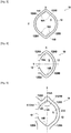
- the figure 1 shows a duct 10 for a part for a turbomachine, in particular a stator part for a turbomachine, such as a pump outlet volute or a gas turbine inlet volute.
- a stator part for a turbomachine such as a pump outlet volute or a gas turbine inlet volute.
- the duct 10 comprises a wall 12 which has in section an internal section S and two internal ridges, a first internal ridge 14A and a second internal ridge 14B.
- Each internal edge 14A, 14B has a radius of curvature R which is greater than or equal to 0.5 mm, preferably greater than or equal to 1 mm and less than or equal to 5 mm, preferably less than or equal to 4 mm.
- the radius of curvature R is equal to 2 mm.
- the radius of curvature R of each internal edge 14A, 14B is measured on a surface internal to the duct 10.
- the wall 12 in particular the internal section S comprises two axes of symmetry, a first axis of symmetry X and a second axis of symmetry Y which are perpendicular to one another.
- the first internal edge 14A is opposite the second internal edge 14B with respect to the second axis of symmetry Y.
- the wall 12 On either side of the first internal ridge 14A, the wall 12 comprises two adjacent portions 12AA, 12AB, each adjacent portion 12AA, 12AB comprising an internal face 16A of the duct 10.
- the internal faces 16A of the two adjacent portions 12AA, 12AB are symmetrical with respect to the first internal edge 14A and with respect to the first axis of symmetry X.
- the wall 12 comprises two adjacent portions 12BA, 12BB, each adjacent portion 12BA, 12BB comprising an internal face 16B to the duct 10.
- the internal faces 16B of the two adjacent portions 12BA, 12BB are symmetrical with respect to the second internal edge 14B and with respect to the first axis of symmetry X.
- each portion 12AA, 12AB adjacent to the first internal edge 14A, in particular the internal face 16A forms with the second axis of symmetry an angle ⁇ which is greater than or equal to 0 °, preferably greater than or equal to 10 °, of preferably greater than or equal to 20 °, preferably greater than or equal to 30, still more preferably greater than or equal to 40 ° and less than or equal to 50 °, preferably less than or equal to 45 °.
- the angle ⁇ is equal to 40 °.
- a wall portion comprising the first internal ridge 14A has a thickness E14 measured along the first axis of symmetry X.
- Each adjacent portion 12AA, 12AB has a thickness E12.
- the thickness E12 is measured in a direction perpendicular to the wall 12.
- the thickness E14 of the wall portion comprising the first internal ridge 14A and the thickness E12 of the two adjacent portions 12AA, 12AB to the first internal ridge 14A are equal.
- a wall portion comprising the second internal ridge 14B has a thickness E14 measured along the first axis of symmetry X.
- Each adjacent portion 12BA, 12BB has a thickness E12.
- the thickness E12 is measured in a direction perpendicular to the wall 12.
- the thickness E14 of the wall portion comprising the second internal ridge 14B and the thickness E12 of the two adjacent portions 12BA, 12BB to the second internal ridge 14B are equal.
- the thickness E14 of the wall portion comprising the first internal ridge 14A and the thickness E14 of the wall portion comprising the second internal ridge 14B are equal. Also, the thickness E14 of the wall portion comprising the first internal ridge 14A and of the wall portion comprising the second internal ridge 14B is equal to the thickness E12 of the adjacent portions 12AA, 12AB to the first internal ridge 14A and portions 12BA, 12BB adjacent to the second internal ridge 14B.
- the embodiment of the figure 2 is similar to the embodiment of the figure 1 .
- the embodiment of the figure 2 differs in particular in that the angle ⁇ between the adjacent portions and the second axis of symmetry Y is equal to 60 ° and the radius of curvature R of the first and of the second internal edge 14A, 14B is equal to 2 mm.
- the embodiment of the figure 3 is similar to the embodiment of the figure 1 .
- the embodiment of the figure 3 differs in particular in that the size of the internal section S and the thickness of the wall 12 are different.
- the embodiment of the figure 4 is similar to the embodiment of the figure 1 .
- the embodiment of the figure 4 differs in particular in that the wall 12 is not continuous in section and has an opening 18.
- the duct 10 has an opening 18 in section and the external shape of the first internal edge 14A differs from the external shape of the second internal edge 14B, it is possible to define the first axis of symmetry X and the second axis of symmetry Y of the internal section S of the wall 12, delimited by the broken lines on the figure 4 .
- the first internal edge 14A is opposite the second internal edge 14B with respect to the second axis of symmetry Y of the wall 12 in section.
- the radius of curvature R of the first and of the second internal edge 14A, 14B is equal to 2 mm.
- the embodiment of the figure 5 is similar to the embodiment of the figure 4 .
- the embodiment of the figure 5 differs in particular in that the wall portion comprising the second internal ridge 14B has a shape external to the duct 10 which is different from the external shape of the wall portion comprising the first internal ridge 14A and in that the thickness E14A of the wall portion comprising the first internal ridge 14A is greater than the thickness E12AA, E12AB of the portions 12AA, 12AB adjacent to the first internal ridge 14A.
- the thickness E14A of the wall portion comprising the first internal ridge 14A is equal to 8 mm and the thickness E12AA, E12AB of the portions 12AA, 12AB adjacent to the first internal ridge 14A is equal to 6 mm.
- the radius of curvature R of the first and of the second internal edge 14A, 14B is equal to 2 mm.
- the wall portion comprising the first internal ridge 14A has a width L14A, measured perpendicular to the thickness E14A of the wall portion comprising the first internal ridge 14A and at half the thickness E14A of the wall portion comprising the first internal edge 14A, equal to 8 mm.
- the embodiment of the figure 6 is similar to the embodiment of the figure 1 .
- the embodiment of the figure 6 differs in particular in that it does not include a first axis of symmetry X.
- the first internal edge 14A and the second internal edge 14B are opposed to each other with respect to the axis of symmetry Y of the internal section S of the wall 12 of the duct 10.
- the first internal edge 14A has an axis of symmetry X 'of the adjacent portions 12AA, 12AB to the first internal edge 14A and the second internal ridge 14B has an axis of symmetry X 'of the portions 12BA, 12BB adjacent to the second internal ridge 14B.
- the axis of symmetry X 'of the first internal edge 14A coincides with the axis of symmetry X' of the second internal edge 14B.
- the axis of symmetry X ' is not an axis of symmetry of the internal section S.
- the radius of curvature R of the first and of the second internal ridge 14A, 14B is equal to 3 mm and the thickness E14B of the wall portion comprising the second internal ridge 14B is equal to 8 mm.
- the thickness E12BA of the adjacent portion 12BA is equal to the thickness E12BB of the adjacent portion 12BB, these thicknesses are equal to the thickness E14B of the wall portion comprising the second internal ridge 14B.
- the embodiment of the figure 7 is similar to the embodiment of the figure 6 .
- the embodiment of the figure 7 differs in particular in that the thickness E14A of the first internal ridge 14A is equal to 6 mm.
- the embodiment of the figure 8 is similar to the embodiment of the figure 1 .
- the embodiment of the figure 8 differs in particular in that it does not include a first axis of symmetry X and a second axis of symmetry Y.
- the second internal edge 14B has an axis of symmetry X ′′ from the adjacent portions 12BA, 12BB to the second internal edge 14B.
- first internal edge 14A does not have an axis of symmetry of the adjacent portions 12AA, 12AB.
- first internal ridge 14A is opposite the second internal ridge 14B.
- the embodiment of the figure 9 is similar to the embodiment of the figure 1 .
- the embodiment of the figure 9 differs in particular in that the duct comprises an internal ridge 14.
- the radius of curvature R of the internal edge 14 is equal to 2 mm and the thickness E14 of the wall portion comprising the internal edge 14 is equal to 5 mm.
- the embodiment of the figure 10 is similar to the embodiment of the figure 9 .
- the embodiment of the figure 10 differs in particular in that the general shape of the internal section S is different.
- the radius of curvature R of the internal ridge 14 is equal to 4 mm and the thickness E14 of the wall portion comprising the internal ridge 14 is equal to 6 mm.
- the embodiment of the figure 11 is similar to the embodiment of the figure 1 .
- the embodiment of the figure 11 differs in particular in that the duct comprises an internal ridge 14, an opening 18 and in that the axis of symmetry X 'of the portions 12A, 12B adjacent to the internal ridge 14 is not an axis of symmetry of the section internal S.
- the radius of curvature R of the internal ridge 14 is equal to 3 mm
- the thickness E14 of the wall portion comprising the internal ridge 14 is equal to 8 mm
- the width L14 of the wall portion comprising the internal edge 14 is equal to 10 mm.
- the thickness E12 of the wall portions adjacent to the internal ridge is equal to 6 mm.
- the embodiment of the figure 12 is similar to the embodiment of the figure 11 .
- the embodiment of the figure 12 differs in particular in that the opening 18 is arranged differently in the wall 12.
- the embodiment of the figure 13 is similar to the embodiment of the figure 11 .
- the embodiment of the figure 13 differs in particular in that the section does not have an opening 18.
- the thickness E12 of the adjacent wall 12A, 12B is equal to 4 mm
- the thickness E14 of the wall portion comprising the internal ridge 14 is equal to 7 mm
- the width L14 of the wall portion comprising the internal edge 14 is equal to 15 mm.
- the radius of curvature R of the internal edge 14 is equal to 2 mm.
- the thickness E14 of the wall portion comprising the internal ridge 14 is equal to 1.75 times the thickness E12 of the wall portions adjacent to the internal ridge and the width L14 of the wall portion comprising the internal ridge 14 is equal to 2.14 times the thickness E14 of the wall portion comprising the internal ridge 14.
- the embodiment of the figure 14 is similar to the embodiment of the figure 12 .
- the embodiment of the figure 14 differs in particular in that the thickness E14 of the wall portion comprising the internal ridge 14 is equal to the thickness E12 of the adjacent wall 12A, 12B.
- the thickness E12 of the adjacent wall 12A, 12B and the thickness E14 of the wall portion comprising the internal edge 14 are equal to 6 mm.
- the radius of curvature R of the internal edge 14 is equal to 2 mm.
- the conduit 10 of the various embodiments presented on the figures 1 to 14 can be produced by additive manufacturing by laser fusion on a powder bed.
Landscapes
- Engineering & Computer Science (AREA)
- Mechanical Engineering (AREA)
- General Engineering & Computer Science (AREA)
- Manufacturing & Machinery (AREA)
- Chemical & Material Sciences (AREA)
- Materials Engineering (AREA)
- Physics & Mathematics (AREA)
- Plasma & Fusion (AREA)
- Automation & Control Theory (AREA)
- Fluid Mechanics (AREA)
- Architecture (AREA)
- Structures Of Non-Positive Displacement Pumps (AREA)
Abstract
Description
- Le présent exposé concerne un conduit pour pièce de stator pour turbomachine, tel qu'une volute de sortie de pompe ou une volute d'entrée de turbine à gaz.
- Dans une turbomachine, des fluides doivent être transportés sous pression entre différents éléments de la turbomachine. Ces fluides (liquides ou gazeux) sous pression exercent des contraintes mécaniques relativement importantes sur les parois des conduits dans lesquels ils circulent.
- Par ailleurs, les différents éléments de la turbomachine peuvent être à des températures différentes de sorte qu'il peut exister des contraintes thermiques dans les différents éléments, par exemple dans les conduits.
- Des conduits présentant une section circulaire peuvent être obtenus par des procédés connus de mise en forme, par fonderie par exemple.
- Des conduits peuvent également être fabriqués par un procédé de fabrication additive par fusion laser sur lit de poudre. Toutefois, la forme circulaire de la section du conduit n'est pas adaptée à un tel procédé de fabrication, notamment en raison de la dimension des conduits.
- Aussi, la forme de la section du conduit a été adaptée au procédé de fabrication additive par fusion laser sur lit de poudre, par exemple en adoptant une section ayant une forme dite de « goutte ».
- Cependant, cette forme de goutte peut s'avérer ne pas être satisfaisante pour tous les cas d'application.
- Le présent exposé vise à remédier au moins en partie à ces inconvénients.
- A cet effet, le présent exposé concerne un conduit pour turbomachine comprenant une paroi comportant une arête interne présentant en section un rayon de courbure supérieur ou égal à 0,5 mm (millimètre), de préférence supérieur ou égal à 1 mm et inférieur ou égal à 5 mm, de préférence inférieur ou égal à 4 mm.
- On comprend que la section de la paroi interne du conduit est dépourvue d'angle vif.
- En effet, lors de la circulation du fluide sous pression dans le conduit, le conduit se déforme et, lorsque la section comporte, sur la surface interne de la paroi, un ou plusieurs angle(s) vif(s), des concentrations de contraintes peuvent survenir. Ces concentrations de contraintes peuvent conduire à des sollicitations trop importantes du conduit et, à terme, à la rupture du conduit. On comprend que la température du fluide circulant dans le conduit peut également provoquer des dilatations thermiques du conduit et donc des concentrations de contraintes, notamment dans l'angle vif. Aussi, on parlera de manière générale de contraintes thermomécaniques subies par la paroi du conduit.
- Grâce à l'arête interne du conduit dépourvue d'angle vif et présentant un rayon de courbure, et non un angle vif, supérieur ou égal à 0,5 mm, de préférence supérieur ou égal à 1 mm, la concentration des contraintes thermomécaniques lors de la déformation du conduit est réduite de sorte que les risques de rupture du conduit sont réduits. Par ailleurs, le rayon de courbure étant et inférieur ou égal à 5 mm, de préférence inférieur ou égal à 4 mm, le conduit peut être réalisé par fabrication additive par fusion laser sur lit de poudre. On comprend que le rayon de courbure est mesuré sur une surface de la paroi qui est interne au conduit.
- Dans certains modes de réalisation, la paroi comprend une portion adjacente à l'arête interne présentant une épaisseur et une portion de paroi comprenant l'arête interne présente une épaisseur supérieure à l'épaisseur de la portion adjacente à l'arête interne.
- On comprend que la portion de paroi comprenant l'arête interne est une portion de la paroi présentant le rayon de courbure R. De même, une portion adjacente à l'arête interne est une portion de paroi ne présentant pas le rayon de courbure R et contiguë à la portion de paroi comprenant l'arête interne.
- Le conduit peut ainsi présenter une meilleure résistance aux contraintes thermomécaniques lors de la déformation tout en présentant une paroi dont la portion comprenant l'arête interne présente une épaisseur plus importante. On peut ainsi avantageusement réduire la masse du conduit en limitant l'épaisseur de la paroi du conduit dans des portions de la paroi qui subissent moins de sollicitations, par exemple des portions de la paroi qui sont adjacentes à l'arête.
- Dans certains modes de réalisation, l'épaisseur de la portion de paroi comprenant l'arête interne est supérieure ou égale à 1,1 fois l'épaisseur de la portion adjacente à l'arête interne, de préférence supérieure ou égale à 1,5 fois l'épaisseur de la portion adjacente à l'arête interne.
- Dans certains modes de réalisation, l'épaisseur de la portion de paroi comprenant l'arête interne est inférieure ou égale à 3 fois l'épaisseur de la portion adjacente à l'arête interne, de préférence inférieure ou égale à 2,5 fois l'épaisseur de la portion adjacente à l'arête interne.
- Dans certains modes de réalisation, la largeur de paroi comprenant l'arête interne est inférieure ou égale 3,5 fois l'épaisseur de la portion de paroi comprenant l'arête interne, de préférence inférieure ou égale à 3 fois l'épaisseur de la portion de paroi comprenant l'arête interne.
- Dans certains modes de réalisation, la paroi comprend deux portions adjacentes à l'arête interne, disposées de part et d'autre de l'arête interne, chaque portion comportant une face interne, les faces internes des deux portions adjacentes étant symétriques par rapport à l'arête interne.
- Le conduit présente une symétrie partielle, au moins au niveau de l'arête interne et des portions de paroi adjacentes à l'arête interne, de sorte que l'écoulement du fluide dans le conduit génère moins de concentration de contraintes thermomécaniques que dans un conduit ne présentant pas de symétrie, même partielle.
- Dans certains modes de réalisation, le conduit comprend deux arêtes internes opposées l'une à l'autre.
- On peut ainsi avoir un conduit présentant une section plus symétrique qu'une section en forme de « goutte » par exemple.
- Dans certains modes de réalisation, le conduit présente en section un axe de symétrie.
- On comprend que la section peut présenter sensiblement une symétrie axiale. Cette symétrie axiale de la section de la paroi du conduit permet une répartition des contraintes plus homogène et réduit les risques de rupture du conduit.
- L'axe de symétrie peut par exemple être confondu avec l'axe de symétrie des faces internes des portions adjacentes à l'arête interne.
- Dans certains modes de réalisation, les portions adjacentes, en particulier les faces internes des portions adjacentes, forment avec un axe perpendiculaire à l'axe de symétrie un angle supérieur ou égal à 0° (degré), de préférence supérieur ou égal à 10°, de préférence supérieur ou égal à 20°, de préférence supérieur ou égal à 30, encore plus de préférence supérieur ou égal à 40° et inférieur ou égal à 50°, de préférence inférieur ou égal à 45°.
- Dans certains modes de réalisation, les deux arêtes internes sont opposées l'une à l'autre par rapport à l'axe de symétrie.
- Dans certains modes de réalisation, le conduit présente en section deux axes de symétrie.
- De préférence, les deux axes de symétrie sont perpendiculaires entre eux.
- Dans certains modes de réalisation, le conduit est une volute de sortie de pompe ou une volute d'entrée de turbine à gaz.
- D'autres caractéristiques et avantages de l'objet du présent exposé ressortiront de la description suivante de modes de réalisation, donnés à titre d'exemples non limitatifs, en référence aux figures annexées.
- [
Fig. 1 ] Lafigure 1 est une vue en coupe d'une section d'un conduit selon un premier mode de réalisation du conduit. - [
Fig. 2 ] Lafigure 2 est une vue en coupe d'une section d'un conduit selon un deuxième mode de réalisation du conduit. - [
Fig. 3 ] Lafigure 3 est une vue en coupe d'une section d'un conduit selon un troisième mode de réalisation du conduit. - [
Fig. 4 ] Lafigure 4 est une vue en coupe d'une section d'un conduit selon un quatrième mode de réalisation du conduit. - [
Fig. 5 ] Lafigure 5 est une vue en coupe d'une section d'un conduit selon un cinquième mode de réalisation du conduit. - [
Fig. 6 ] Lafigure 6 est une vue en coupe d'une section d'un conduit selon un sixième mode de réalisation du conduit. - [
Fig. 7 ] Lafigure 7 est une vue en coupe d'une section d'un conduit selon un septième mode de réalisation du conduit. - [
Fig. 8 ] Lafigure 8 est une vue en coupe d'une section d'un conduit selon un huitième mode de réalisation du conduit. - [
Fig. 9 ] Lafigure 9 est une vue en coupe d'une section d'un conduit selon un neuvième mode de réalisation du conduit. - [
Fig. 10 ] Lafigure 10 est une vue en coupe d'une section d'un conduit selon un dixième mode de réalisation du conduit. - [
Fig. 11 ] Lafigure 11 est une vue en coupe d'une section d'un conduit selon un onzième mode de réalisation du conduit. - [
Fig. 12 ] Lafigure 12 est une vue en coupe d'une section d'un conduit selon un douzième mode de réalisation du conduit. - [
Fig. 13 ] Lafigure 13 est une vue en coupe d'une section d'un conduit selon un treizième mode de réalisation du conduit. - [
Fig. 14 ] Lafigure 14 est une vue en coupe d'une section d'un conduit selon un quatorzième mode de réalisation du conduit. - Sur l'ensemble des figures, les éléments en commun sont repérés par des références numériques identiques.
- La
figure 1 représente un conduit 10 pour pièce pour turbomachine, en particulier une pièce de stator pour turbomachine, tel qu'une volute de sortie de pompe ou une volute d'entrée de turbine à gaz. - Dans le mode de réalisation de la
figure 1 , le conduit 10 comprend une paroi 12 qui présente en section une section interne S et deux arêtes internes, une première arête interne 14A et une deuxième arête interne 14B. Chaque arête interne 14A, 14B présente un rayon de courbure R qui est supérieur ou égal à 0,5 mm, de préférence supérieur ou égal à 1 mm et inférieur ou égal à 5 mm, de préférence inférieur ou égal à 4 mm. Par exemple, dans le mode de réalisation de lafigure 1 , le rayon de courbure R est égal à 2 mm. Le rayon de courbure R de chaque arête interne 14A, 14B est mesuré sur une surface interne au conduit 10. - Dans le mode de réalisation de la
figure 1 , la paroi 12, en particulier la section interne S, comprend deux axes de symétrie, un premier axe de symétrie X et un deuxième axe de symétrie Y qui sont perpendiculaires l'un à l'autre. - Dans le mode de réalisation de la
figure 1 , la première arête interne 14A est opposée à la deuxième arête interne 14B par rapport au deuxième axe de symétrie Y. - De part et d'autre la première arête interne 14A, la paroi 12 comprend deux portions adjacentes 12AA, 12AB, chaque portion adjacente 12AA, 12AB comportant une face interne 16A au conduit 10. Les faces internes 16A des deux portions adjacentes 12AA, 12AB sont symétriques par rapport à la première arête interne 14A et par rapport au premier axe de symétrie X.
- De même, de part et d'autre de la deuxième arête interne 14B, la paroi 12 comprend deux portions adjacentes 12BA, 12BB, chaque portion adjacente 12BA, 12BB comportant une face interne 16B au conduit 10. Les faces internes 16B des deux portions adjacentes 12BA, 12BB sont symétriques par rapport à la deuxième arête interne 14B et par rapport au premier axe de symétrie X.
- Dans le mode de réalisation de la
figure 1 , chaque portion adjacente 12AA, 12AB à la première arête interne 14A, en particulier la face interne 16A, forme avec le deuxième axe de symétrie un angle α qui est supérieur ou égal à 0°, de préférence supérieur ou égal à 10°, de préférence supérieur ou égal à 20°, de préférence supérieur ou égal à 30, encore plus de préférence supérieur ou égal à 40° et inférieur ou égal à 50°, de préférence inférieur ou égal à 45°. Il en va de même des portions adjacentes 12BA, 12BB à la deuxième arête interne 14B, en particulier les faces internes 16B. Dans le mode de réalisation de lafigure 1 , l'angle α est égal à 40°. - Dans le mode de réalisation de la
figure 1 , une portion de paroi comprenant la première arête interne 14A présente une épaisseur E14 mesurée selon le premier axe de symétrie X. Chaque portion adjacente 12AA, 12AB présente une épaisseur E12. L'épaisseur E12 est mesurée selon une direction perpendiculaire à la paroi 12. - Dans le mode de réalisation de la
figure 1 , l'épaisseur E14 de la portion de paroi comprenant la première arête interne 14A et l'épaisseur E12 des deux portions adjacentes 12AA, 12AB à la première arête interne 14A sont égales. - Dans le mode de réalisation de la
figure 1 , une portion de paroi comprenant la deuxième arête interne 14B présente une épaisseur E14 mesurée selon le premier axe de symétrie X. Chaque portion adjacente 12BA, 12BB présente une épaisseur E12. L'épaisseur E12 est mesurée selon une direction perpendiculaire à la paroi 12. - Dans le mode de réalisation de la
figure 1 , l'épaisseur E14 de la portion de paroi comprenant la deuxième arête interne 14B et l'épaisseur E12 des deux portions adjacentes 12BA, 12BB à la deuxième arête interne 14B sont égales. - De plus, dans le mode de réalisation de la
figure 1 , l'épaisseur E14 de la portion de paroi comprenant la première arête interne 14A et l'épaisseur E14 de la portion de paroi comprenant la deuxième arête interne 14B sont égales. Aussi, l'épaisseur E14 de la portion de paroi comprenant la première arête interne 14A et de la portion de paroi comprenant la deuxième arête interne 14B est égale à l'épaisseur E12 des portions adjacentes 12AA, 12AB à la première arête interne 14A et des portions adjacentes 12BA, 12BB à la deuxième arête interne 14B. - Dans ce qui suit, les éléments communs aux différents modes de réalisation sont identifiés par les mêmes références numériques.
- Le mode de réalisation de la
figure 2 est similaire au mode de réalisation de lafigure 1 . Le mode de réalisation de lafigure 2 diffère notamment en ce que l'angle α entre les portions adjacentes et le deuxième axe de symétrie Y est égal à 60° et le rayon de courbure R de la première et de la deuxième arête interne 14A, 14B est égal à 2 mm. - Le mode de réalisation de la
figure 3 est similaire au mode de réalisation de lafigure 1 . Le mode de réalisation de lafigure 3 diffère notamment en ce que la taille de la section interne S et l'épaisseur de la paroi 12 sont différentes. - Le mode de réalisation de la
figure 4 est similaire au mode de réalisation de lafigure 1 . Le mode de réalisation de lafigure 4 diffère notamment en ce que la paroi 12 n'est pas continue en section et présente une ouverture 18. - Bien que le conduit 10 présente en section une ouverture 18 et que la forme externe de la première arête interne 14A diffère de la forme externe de la deuxième arête interne 14B, on peut définir le premier axe de symétrie X et le deuxième axe de symétrie Y de la section interne S de la paroi 12, délimitée par les traits discontinus sur la
figure 4 . - La première arête interne 14A est opposé à la deuxième arête interne 14B par rapport au deuxième axe de symétrie Y de la paroi 12 en section. Le rayon de courbure R de la première et de la deuxième arête interne 14A, 14B est égal à 2 mm.
- Le mode de réalisation de la
figure 5 est similaire au mode de réalisation de lafigure 4 . Le mode de réalisation de lafigure 5 diffère notamment en ce que la portion de paroi comprenant la deuxième arête interne 14B présente une forme externe au conduit 10 qui est différente de la forme externe de la portion de paroi comprenant la première arête interne 14A et en ce que l'épaisseur E14A de la portion de paroi comprenant la première arête interne 14A est supérieure à l'épaisseur E12AA, E12AB des portions adjacentes 12AA, 12AB à la première arête interne 14A. - Dans le mode de réalisation de la
figure 5 , l'épaisseur E14A de la portion de paroi comprenant la première arête interne 14A est égale à 8 mm et l'épaisseur E12AA, E12AB des portions adjacentes 12AA, 12AB à la première arête interne 14A est égale à 6 mm. Le rayon de courbure R de la première et de la deuxième arête interne 14A, 14B est égal à 2 mm. La portion de paroi comprenant la première arête interne 14A présente une largeur L14A, mesurée perpendiculairement à l'épaisseur E14A de la portion de paroi comprenant la première arête interne 14A et à la moitié de l'épaisseur E14A de la portion de paroi comprenant la première arête interne 14A, égale à 8 mm. - Le mode de réalisation de la
figure 6 est similaire au mode de réalisation de lafigure 1 . Le mode de réalisation de lafigure 6 diffère notamment en ce qu'il ne comprend pas de premier axe de symétrie X. La première arête interne 14A et la deuxième arête interne 14B sont opposées l'une à l'autre par rapport à l'axe de symétrie Y de la section interne S de la paroi 12 du conduit 10. La première arête interne 14A présente un axe de symétrie X' des portions adjacentes 12AA, 12AB à la première arête interne 14A et la deuxième arête interne 14B présente un axe de symétrie X' des portions adjacentes 12BA, 12BB à la deuxième arête interne 14B. L'axe de symétrie X' de la première arête interne 14A est confondu avec l'axe de symétrie X' de la deuxième arête interne 14B. Toutefois, dans le mode de réalisation de lafigure 6 , l'axe de symétrie X' n'est pas un axe de symétrie de la section interne S. - Dans le mode de réalisation de la
figure 6 , le rayon de courbure R de la première et de la deuxième arête interne 14A, 14B est égal à 3 mm et l'épaisseur E14B de la portion de paroi comprenant la deuxième arête interne 14B est égale à 8 mm. L'épaisseur E12BA de la portion adjacentes 12BA est égale à l'épaisseur E12BB de la portion adjacente 12BB, ces épaisseurs sont égales à l'épaisseur E14B de la portion de paroi comprenant la deuxième arête interne 14B. - Le mode de réalisation de la
figure 7 est similaire au mode de réalisation de lafigure 6 . Le mode de réalisation de lafigure 7 diffère notamment en ce que l'épaisseur E14A de la première arête interne 14A est égale à 6 mm. - Le mode de réalisation de la
figure 8 est similaire au mode de réalisation de lafigure 1 . Le mode de réalisation de lafigure 8 diffère notamment en ce qu'il ne comprend pas de premier axe de symétrie X et de deuxième axe de symétrie Y. La deuxième arête interne 14B présente un axe de symétrie X" des portions adjacentes 12BA, 12BB à la deuxième arête interne 14B. La première arête interne 14A ne présente pas d'axe de symétrie des portions adjacentes 12AA, 12AB. - On peut dire que la première arête interne 14A est opposée à la deuxième arête interne 14B.
- Le mode de réalisation de la
figure 9 est similaire au mode de réalisation de lafigure 1 . Le mode de réalisation de lafigure 9 diffère notamment en ce que le conduit comprend une arête interne 14. - Dans le mode de réalisation de la
figure 9 , le rayon de courbure R de l'arête interne 14 est égal à 2 mm et l'épaisseur E14 de la portion de paroi comprenant l'arête interne 14 est égale à 5 mm. - Le mode de réalisation de la
figure 10 est similaire au mode de réalisation de lafigure 9 . Le mode de réalisation de lafigure 10 diffère notamment en ce que la forme générale de la section interne S est différente. - Dans le mode de réalisation de la
figure 10 , le rayon de courbure R de l'arête interne 14 est égal à 4 mm et l'épaisseur E14 de la portion de paroi comprenant l'arête interne 14 est égale à 6 mm. - Le mode de réalisation de la
figure 11 est similaire au mode de réalisation de lafigure 1 . Le mode de réalisation de lafigure 11 diffère notamment en ce que le conduit comprend une arête interne 14, une ouverture 18 et en ce que l'axe de symétrie X' des portions adjacentes 12A, 12B à l'arête interne 14 n'est pas un axe de symétrie de la section interne S. - Dans le mode de réalisation de la
figure 11 , le rayon de courbure R de l'arête interne 14 est égal à 3 mm, l'épaisseur E14 de la portion de paroi comprenant l'arête interne 14 est égale à 8 mm et la largeur L14 de la portion de paroi comprenant l'arête interne 14 est égale à 10 mm. L'épaisseur E12 des portions de paroi adjacentes à l'arête interne est égale à 6 mm. - Le mode de réalisation de la
figure 12 est similaire au mode de réalisation de lafigure 11 . Le mode de réalisation de lafigure 12 diffère notamment en ce que l'ouverture 18 est disposée différemment dans la paroi 12. - Le mode de réalisation de la
figure 13 est similaire au mode de réalisation de lafigure 11 . Le mode de réalisation de lafigure 13 diffère notamment en ce que la section ne comporte pas d'ouverture 18. - Dans le mode de réalisation de la
figure 13 , l'épaisseur E12 de la paroi adjacente 12A, 12B est égal à 4 mm, l'épaisseur E14 de la portion de paroi comprenant l'arête interne 14 est égale à 7 mm et la largeur L14 de la portion de paroi comprenant l'arête interne 14 est égale à 15 mm. Le rayon de courbure R de l'arête interne 14 est égal à 2 mm. Aussi, l'épaisseur E14 de la portion de paroi comprenant l'arête interne 14 est égale à 1,75 fois l'épaisseur E12 des portions de paroi adjacentes à l'arête interne et la largeur L14 de la portion de paroi comprenant l'arête interne 14 est égale à 2,14 fois l'épaisseur E14 de la portion de paroi comprenant l'arête interne 14. - Le mode de réalisation de la
figure 14 est similaire au mode de réalisation de lafigure 12 . Le mode de réalisation de lafigure 14 diffère notamment en ce que l'épaisseur E14 de la portion de paroi comprenant l'arête interne 14 est égale à l'épaisseur E12 de la paroi adjacente 12A, 12B. - Dans le mode de réalisation de la
figure 14 , l'épaisseur E12 de la paroi adjacente 12A, 12B et l'épaisseur E14 de la portion de paroi comprenant l'arête interne 14 sont égales à 6 mm. Le rayon de courbure R de l'arête interne 14 est égal à 2 mm. - Le conduit 10 des différents modes de réalisation présentés sur les
figures 1 à 14 peut être réalisé par fabrication additive par fusion laser sur lit de poudre. - Quoique le présent exposé ait été décrit en se référant à un exemple de réalisation spécifique, il est évident que des différentes modifications et changements peuvent être effectués sur ces exemples sans sortir de la portée générale de l'invention telle que définie par les revendications. En outre, des caractéristiques individuelles des différents modes de réalisation évoqués peuvent être combinées dans des modes de réalisation additionnels. Par conséquent, la description et les dessins doivent être considérés dans un sens illustratif plutôt que restrictif.
Claims (8)
- Conduit (10) pour turbomachine comprenant une paroi (12) comportant une arête interne (14 ; 14A, 14B) présentant en section un rayon de courbure (R) supérieur ou égal à 0,5 mm, de préférence supérieur ou égal à 1 mm et inférieur ou égal à 5 mm, de préférence inférieur ou égal à 4 mm, le conduit (10) étant une volute de sortie de pompe ou une volute d'entrée de turbine à gaz.
- Conduit (10) selon la revendication 1, dans lequel la paroi (12) comprend une portion adjacente (12A, 12B ; 12AA, 12AB, 12BA, 12BB) à l'arête interne (14 ; 14A, 14B) présentant une épaisseur (E12) et une portion de paroi comprenant l'arête interne présente une épaisseur (E14 ; E14A) supérieure à l'épaisseur (E12) de la portion adjacente (12A, 12B ; 12AA, 12AB, 12BA, 12BB) à l'arête interne.
- Conduit (10) selon la revendication 2, dans lequel l'épaisseur (E14 ; E14A) de la portion de paroi comprenant l'arête interne est supérieure ou égale à 1,1 fois l'épaisseur (E12) de la portion adjacente (12A, 12B ; 12AA, 12AB, 12BA, 12BB) à l'arête interne, de préférence supérieure ou égale à 1,5 fois l'épaisseur de la portion adjacente (12A, 12B ; 12AA, 12AB, 12BA, 12BB) à l'arête interne.
- Conduit (10) selon la revendication 3, dans lequel l'épaisseur (E14, E14A) de la portion de paroi comprenant l'arête interne est inférieure ou égale à 3 fois l'épaisseur de la portion adjacente (12A, 12B ; 12AA, 12AB, 12BA, 12BB) à l'arête interne, de préférence inférieure ou égale à 2,5 fois l'épaisseur de la portion adjacente (12A, 12B ; 12AA, 12AB, 12BA, 12BB) à l'arête interne.
- Conduit (10) selon l'une quelconque des revendications 1 à 4, dans lequel la paroi (12) comprend deux portions adjacentes (12A, 12B ; 12AA, 12AB, 12BA, 12BB) à l'arête interne (14 ; 14A, 14B), disposées de part et d'autre de l'arête interne (14 ; 14A, 14B), chaque portion (12A, 12B ; 12AA, 12AB, 12BA, 12BB) comportant une face interne (16 ; 16A, 16B), les faces internes (16 ; 16A, 16B) des deux portions adjacentes (12A, 12B ; 12AA, 12AB, 12BA, 12BB) étant symétriques par rapport à l'arête interne (14 ; 14A, 14B).
- Conduit (10) selon l'une quelconque des revendications 1 à 5, comprenant deux arêtes internes (14A, 14B) opposées l'une à l'autre.
- Conduit (10) selon l'une quelconque des revendications 1 à 6, présentant en section un axe de symétrie (X).
- Conduit (10) selon l'une quelconque des revendications 1 à 7, présentant en section deux axes de symétrie (X, Y).
Applications Claiming Priority (1)
| Application Number | Priority Date | Filing Date | Title |
|---|---|---|---|
| FR1904311A FR3095470B1 (fr) | 2019-04-24 | 2019-04-24 | Conduit pour piece de stator pour turbomachine |
Publications (2)
| Publication Number | Publication Date |
|---|---|
| EP3730740A1 true EP3730740A1 (fr) | 2020-10-28 |
| EP3730740B1 EP3730740B1 (fr) | 2022-07-06 |
Family
ID=67441455
Family Applications (1)
| Application Number | Title | Priority Date | Filing Date |
|---|---|---|---|
| EP20169774.5A Active EP3730740B1 (fr) | 2019-04-24 | 2020-04-16 | Conduit pour pièce de stator pour turbomachine |
Country Status (3)
| Country | Link |
|---|---|
| EP (1) | EP3730740B1 (fr) |
| ES (1) | ES2927845T3 (fr) |
| FR (1) | FR3095470B1 (fr) |
Citations (4)
| Publication number | Priority date | Publication date | Assignee | Title |
|---|---|---|---|---|
| DE10022052A1 (de) * | 1999-05-26 | 2001-03-01 | Gillet Heinrich Gmbh | Turbinengehäuse für Abgasturbolader |
| DE102004060409A1 (de) * | 2004-12-14 | 2006-06-29 | Schott Ag | Glasrohr für technische Anwendungen und Verfahren zu dessen Herstellung |
| EP2740905A1 (fr) * | 2012-12-07 | 2014-06-11 | Techspace Aero S.A. | Bec de séparation de turbomachine axiale avec dispositif de dégivrage, compresseur et turbomachine associés |
| FR3063920A1 (fr) * | 2017-03-14 | 2018-09-21 | Zodiac Aero Duct Systems | Tuyauterie specifique pour moteur d'aeronef et procede de fabrication associe |
Family Cites Families (2)
| Publication number | Priority date | Publication date | Assignee | Title |
|---|---|---|---|---|
| CN201836600U (zh) * | 2010-09-30 | 2011-05-18 | 上海宝洋环保科技有限公司 | 一种不易结垢的管道 |
| FR3006998B1 (fr) * | 2013-06-18 | 2015-06-05 | Snecma | Ventilation d'une nacelle de turbomachine |
-
2019
- 2019-04-24 FR FR1904311A patent/FR3095470B1/fr active Active
-
2020
- 2020-04-16 EP EP20169774.5A patent/EP3730740B1/fr active Active
- 2020-04-16 ES ES20169774T patent/ES2927845T3/es active Active
Patent Citations (4)
| Publication number | Priority date | Publication date | Assignee | Title |
|---|---|---|---|---|
| DE10022052A1 (de) * | 1999-05-26 | 2001-03-01 | Gillet Heinrich Gmbh | Turbinengehäuse für Abgasturbolader |
| DE102004060409A1 (de) * | 2004-12-14 | 2006-06-29 | Schott Ag | Glasrohr für technische Anwendungen und Verfahren zu dessen Herstellung |
| EP2740905A1 (fr) * | 2012-12-07 | 2014-06-11 | Techspace Aero S.A. | Bec de séparation de turbomachine axiale avec dispositif de dégivrage, compresseur et turbomachine associés |
| FR3063920A1 (fr) * | 2017-03-14 | 2018-09-21 | Zodiac Aero Duct Systems | Tuyauterie specifique pour moteur d'aeronef et procede de fabrication associe |
Also Published As
| Publication number | Publication date |
|---|---|
| ES2927845T3 (es) | 2022-11-11 |
| FR3095470B1 (fr) | 2021-10-29 |
| EP3730740B1 (fr) | 2022-07-06 |
| FR3095470A1 (fr) | 2020-10-30 |
Similar Documents
| Publication | Publication Date | Title |
|---|---|---|
| EP0636825B1 (fr) | Système de raccordement d'un tuyau véhiculant un fluide chaud à un organe en matière plastique et son utilisation dans un moteur à combustion interne | |
| EP2129878B1 (fr) | Procede d'assemblage de deux pieces bout a bout ayant des coefficients de dilatation differents et assemblage ainsi obtenu | |
| FR3062415B1 (fr) | Rotor de turbine de turbomachine a ventilation par lamage | |
| WO2000022339A1 (fr) | Assemblage filete integral de deux tubes metalliques | |
| EP3347572B1 (fr) | Turbine de turbomachine comprenant un étage distributeur en matériau composite à matrice céramique | |
| FR2961554A1 (fr) | Secteur angulaire de redresseur pour compresseur de turbomachine, redresseur de turbomachine et turbomachine comprenant un tel secteur | |
| FR3107919A1 (fr) | Aube creuse de turbomachine et plateforme inter-aubes équipées de saillies perturbatrices de flux de refroidissement | |
| EP3730740B1 (fr) | Conduit pour pièce de stator pour turbomachine | |
| EP3963184A1 (fr) | Ensemble d'anneau de turbine monté sur entretoise | |
| FR2934797A1 (fr) | Procede et outil pour casser un angle. | |
| EP4680840A1 (fr) | Ensemble d'anneau de turbine à pions axiaux améliorés | |
| FR2957973A1 (fr) | Tube de degazage d'un turboreacteur, procede de montage d'un tel tube et turboreacteur avec un tel tube | |
| FR3063920A1 (fr) | Tuyauterie specifique pour moteur d'aeronef et procede de fabrication associe | |
| EP3985286B1 (fr) | Raccord vissé pour moteur-fusée | |
| EP4445005B1 (fr) | Ensemble de distribution de carburant pour turbomachine | |
| EP3568574B1 (fr) | Ensemble d'anneau de turbine | |
| FR3162459A1 (fr) | Turbine pour turbomachine | |
| FR3094031A1 (fr) | Ensemble pour une turbomachine | |
| FR2957974A1 (fr) | Tube de degazage d'un turboreacteur, procede de montage d'un tel tube et turboreacteur avec un tel tube | |
| FR3141207A1 (fr) | Anneau d’étanchéité pour turbine démontable par l’amont | |
| FR3053083B1 (fr) | Anneau de carenage de roue a aubes | |
| FR3152533A1 (fr) | Carter pour une turbine ou turbomachine d’aeronef | |
| FR3073596A1 (fr) | Assemblage tube/bride ameliore pour systeme de pressurisation d'un engin aeronautique | |
| WO2025046203A1 (fr) | Ensemble pour turbomachine | |
| FR3126471A1 (fr) | Ensemble de turbomachine |
Legal Events
| Date | Code | Title | Description |
|---|---|---|---|
| PUAI | Public reference made under article 153(3) epc to a published international application that has entered the european phase |
Free format text: ORIGINAL CODE: 0009012 |
|
| STAA | Information on the status of an ep patent application or granted ep patent |
Free format text: STATUS: REQUEST FOR EXAMINATION WAS MADE |
|
| 17P | Request for examination filed |
Effective date: 20200416 |
|
| AK | Designated contracting states |
Kind code of ref document: A1 Designated state(s): AL AT BE BG CH CY CZ DE DK EE ES FI FR GB GR HR HU IE IS IT LI LT LU LV MC MK MT NL NO PL PT RO RS SE SI SK SM TR |
|
| AX | Request for extension of the european patent |
Extension state: BA ME |
|
| RAP3 | Party data changed (applicant data changed or rights of an application transferred) |
Owner name: ARIANEGROUP SAS |
|
| GRAP | Despatch of communication of intention to grant a patent |
Free format text: ORIGINAL CODE: EPIDOSNIGR1 |
|
| STAA | Information on the status of an ep patent application or granted ep patent |
Free format text: STATUS: GRANT OF PATENT IS INTENDED |
|
| INTG | Intention to grant announced |
Effective date: 20220222 |
|
| GRAS | Grant fee paid |
Free format text: ORIGINAL CODE: EPIDOSNIGR3 |
|
| GRAA | (expected) grant |
Free format text: ORIGINAL CODE: 0009210 |
|
| STAA | Information on the status of an ep patent application or granted ep patent |
Free format text: STATUS: THE PATENT HAS BEEN GRANTED |
|
| AK | Designated contracting states |
Kind code of ref document: B1 Designated state(s): AL AT BE BG CH CY CZ DE DK EE ES FI FR GB GR HR HU IE IS IT LI LT LU LV MC MK MT NL NO PL PT RO RS SE SI SK SM TR |
|
| REG | Reference to a national code |
Ref country code: AT Ref legal event code: REF Ref document number: 1503020 Country of ref document: AT Kind code of ref document: T Effective date: 20220715 Ref country code: CH Ref legal event code: EP |
|
| REG | Reference to a national code |
Ref country code: DE Ref legal event code: R096 Ref document number: 602020003838 Country of ref document: DE |
|
| REG | Reference to a national code |
Ref country code: IE Ref legal event code: FG4D Free format text: LANGUAGE OF EP DOCUMENT: FRENCH |
|
| REG | Reference to a national code |
Ref country code: NL Ref legal event code: FP |
|
| REG | Reference to a national code |
Ref country code: SE Ref legal event code: TRGR Ref country code: LT Ref legal event code: MG9D |
|
| REG | Reference to a national code |
Ref country code: ES Ref legal event code: FG2A Ref document number: 2927845 Country of ref document: ES Kind code of ref document: T3 Effective date: 20221111 |
|
| PG25 | Lapsed in a contracting state [announced via postgrant information from national office to epo] |
Ref country code: RS Free format text: LAPSE BECAUSE OF FAILURE TO SUBMIT A TRANSLATION OF THE DESCRIPTION OR TO PAY THE FEE WITHIN THE PRESCRIBED TIME-LIMIT Effective date: 20220706 Ref country code: PT Free format text: LAPSE BECAUSE OF FAILURE TO SUBMIT A TRANSLATION OF THE DESCRIPTION OR TO PAY THE FEE WITHIN THE PRESCRIBED TIME-LIMIT Effective date: 20221107 Ref country code: NO Free format text: LAPSE BECAUSE OF FAILURE TO SUBMIT A TRANSLATION OF THE DESCRIPTION OR TO PAY THE FEE WITHIN THE PRESCRIBED TIME-LIMIT Effective date: 20221006 Ref country code: LV Free format text: LAPSE BECAUSE OF FAILURE TO SUBMIT A TRANSLATION OF THE DESCRIPTION OR TO PAY THE FEE WITHIN THE PRESCRIBED TIME-LIMIT Effective date: 20220706 Ref country code: LT Free format text: LAPSE BECAUSE OF FAILURE TO SUBMIT A TRANSLATION OF THE DESCRIPTION OR TO PAY THE FEE WITHIN THE PRESCRIBED TIME-LIMIT Effective date: 20220706 Ref country code: FI Free format text: LAPSE BECAUSE OF FAILURE TO SUBMIT A TRANSLATION OF THE DESCRIPTION OR TO PAY THE FEE WITHIN THE PRESCRIBED TIME-LIMIT Effective date: 20220706 |
|
| REG | Reference to a national code |
Ref country code: AT Ref legal event code: MK05 Ref document number: 1503020 Country of ref document: AT Kind code of ref document: T Effective date: 20220706 |
|
| PG25 | Lapsed in a contracting state [announced via postgrant information from national office to epo] |
Ref country code: PL Free format text: LAPSE BECAUSE OF FAILURE TO SUBMIT A TRANSLATION OF THE DESCRIPTION OR TO PAY THE FEE WITHIN THE PRESCRIBED TIME-LIMIT Effective date: 20220706 Ref country code: IS Free format text: LAPSE BECAUSE OF FAILURE TO SUBMIT A TRANSLATION OF THE DESCRIPTION OR TO PAY THE FEE WITHIN THE PRESCRIBED TIME-LIMIT Effective date: 20221106 Ref country code: GR Free format text: LAPSE BECAUSE OF FAILURE TO SUBMIT A TRANSLATION OF THE DESCRIPTION OR TO PAY THE FEE WITHIN THE PRESCRIBED TIME-LIMIT Effective date: 20221007 |
|
| REG | Reference to a national code |
Ref country code: DE Ref legal event code: R082 Ref document number: 602020003838 Country of ref document: DE Representative=s name: CBDL PATENTANWAELTE GBR, DE Ref country code: DE Ref legal event code: R082 Ref document number: 602020003838 Country of ref document: DE Representative=s name: CBDL PATENTANWAELTE EGBR, DE |
|
| REG | Reference to a national code |
Ref country code: DE Ref legal event code: R097 Ref document number: 602020003838 Country of ref document: DE |
|
| PG25 | Lapsed in a contracting state [announced via postgrant information from national office to epo] |
Ref country code: SM Free format text: LAPSE BECAUSE OF FAILURE TO SUBMIT A TRANSLATION OF THE DESCRIPTION OR TO PAY THE FEE WITHIN THE PRESCRIBED TIME-LIMIT Effective date: 20220706 Ref country code: RO Free format text: LAPSE BECAUSE OF FAILURE TO SUBMIT A TRANSLATION OF THE DESCRIPTION OR TO PAY THE FEE WITHIN THE PRESCRIBED TIME-LIMIT Effective date: 20220706 Ref country code: DK Free format text: LAPSE BECAUSE OF FAILURE TO SUBMIT A TRANSLATION OF THE DESCRIPTION OR TO PAY THE FEE WITHIN THE PRESCRIBED TIME-LIMIT Effective date: 20220706 Ref country code: CZ Free format text: LAPSE BECAUSE OF FAILURE TO SUBMIT A TRANSLATION OF THE DESCRIPTION OR TO PAY THE FEE WITHIN THE PRESCRIBED TIME-LIMIT Effective date: 20220706 Ref country code: AT Free format text: LAPSE BECAUSE OF FAILURE TO SUBMIT A TRANSLATION OF THE DESCRIPTION OR TO PAY THE FEE WITHIN THE PRESCRIBED TIME-LIMIT Effective date: 20220706 |
|
| PLBE | No opposition filed within time limit |
Free format text: ORIGINAL CODE: 0009261 |
|
| STAA | Information on the status of an ep patent application or granted ep patent |
Free format text: STATUS: NO OPPOSITION FILED WITHIN TIME LIMIT |
|
| PG25 | Lapsed in a contracting state [announced via postgrant information from national office to epo] |
Ref country code: SK Free format text: LAPSE BECAUSE OF FAILURE TO SUBMIT A TRANSLATION OF THE DESCRIPTION OR TO PAY THE FEE WITHIN THE PRESCRIBED TIME-LIMIT Effective date: 20220706 Ref country code: EE Free format text: LAPSE BECAUSE OF FAILURE TO SUBMIT A TRANSLATION OF THE DESCRIPTION OR TO PAY THE FEE WITHIN THE PRESCRIBED TIME-LIMIT Effective date: 20220706 |
|
| 26N | No opposition filed |
Effective date: 20230411 |
|
| PG25 | Lapsed in a contracting state [announced via postgrant information from national office to epo] |
Ref country code: AL Free format text: LAPSE BECAUSE OF FAILURE TO SUBMIT A TRANSLATION OF THE DESCRIPTION OR TO PAY THE FEE WITHIN THE PRESCRIBED TIME-LIMIT Effective date: 20220706 |
|
| P01 | Opt-out of the competence of the unified patent court (upc) registered |
Effective date: 20230612 |
|
| PG25 | Lapsed in a contracting state [announced via postgrant information from national office to epo] |
Ref country code: SI Free format text: LAPSE BECAUSE OF FAILURE TO SUBMIT A TRANSLATION OF THE DESCRIPTION OR TO PAY THE FEE WITHIN THE PRESCRIBED TIME-LIMIT Effective date: 20220706 |
|
| PG25 | Lapsed in a contracting state [announced via postgrant information from national office to epo] |
Ref country code: LU Free format text: LAPSE BECAUSE OF NON-PAYMENT OF DUE FEES Effective date: 20230416 |
|
| PG25 | Lapsed in a contracting state [announced via postgrant information from national office to epo] |
Ref country code: MC Free format text: LAPSE BECAUSE OF FAILURE TO SUBMIT A TRANSLATION OF THE DESCRIPTION OR TO PAY THE FEE WITHIN THE PRESCRIBED TIME-LIMIT Effective date: 20220706 |
|
| PG25 | Lapsed in a contracting state [announced via postgrant information from national office to epo] |
Ref country code: MC Free format text: LAPSE BECAUSE OF FAILURE TO SUBMIT A TRANSLATION OF THE DESCRIPTION OR TO PAY THE FEE WITHIN THE PRESCRIBED TIME-LIMIT Effective date: 20220706 |
|
| REG | Reference to a national code |
Ref country code: IE Ref legal event code: MM4A |
|
| PG25 | Lapsed in a contracting state [announced via postgrant information from national office to epo] |
Ref country code: IE Free format text: LAPSE BECAUSE OF NON-PAYMENT OF DUE FEES Effective date: 20230416 |
|
| PG25 | Lapsed in a contracting state [announced via postgrant information from national office to epo] |
Ref country code: IE Free format text: LAPSE BECAUSE OF NON-PAYMENT OF DUE FEES Effective date: 20230416 |
|
| PG25 | Lapsed in a contracting state [announced via postgrant information from national office to epo] |
Ref country code: HR Free format text: LAPSE BECAUSE OF FAILURE TO SUBMIT A TRANSLATION OF THE DESCRIPTION OR TO PAY THE FEE WITHIN THE PRESCRIBED TIME-LIMIT Effective date: 20220706 |
|
| PG25 | Lapsed in a contracting state [announced via postgrant information from national office to epo] |
Ref country code: HR Free format text: LAPSE BECAUSE OF FAILURE TO SUBMIT A TRANSLATION OF THE DESCRIPTION OR TO PAY THE FEE WITHIN THE PRESCRIBED TIME-LIMIT Effective date: 20220706 |
|
| PG25 | Lapsed in a contracting state [announced via postgrant information from national office to epo] |
Ref country code: BG Free format text: LAPSE BECAUSE OF FAILURE TO SUBMIT A TRANSLATION OF THE DESCRIPTION OR TO PAY THE FEE WITHIN THE PRESCRIBED TIME-LIMIT Effective date: 20220706 |
|
| PG25 | Lapsed in a contracting state [announced via postgrant information from national office to epo] |
Ref country code: BG Free format text: LAPSE BECAUSE OF FAILURE TO SUBMIT A TRANSLATION OF THE DESCRIPTION OR TO PAY THE FEE WITHIN THE PRESCRIBED TIME-LIMIT Effective date: 20220706 |
|
| PGFP | Annual fee paid to national office [announced via postgrant information from national office to epo] |
Ref country code: NL Payment date: 20250418 Year of fee payment: 6 |
|
| PGFP | Annual fee paid to national office [announced via postgrant information from national office to epo] |
Ref country code: DE Payment date: 20250422 Year of fee payment: 6 |
|
| PGFP | Annual fee paid to national office [announced via postgrant information from national office to epo] |
Ref country code: ES Payment date: 20250530 Year of fee payment: 6 |
|
| PGFP | Annual fee paid to national office [announced via postgrant information from national office to epo] |
Ref country code: IT Payment date: 20250424 Year of fee payment: 6 Ref country code: BE Payment date: 20250418 Year of fee payment: 6 |
|
| PGFP | Annual fee paid to national office [announced via postgrant information from national office to epo] |
Ref country code: FR Payment date: 20250425 Year of fee payment: 6 |
|
| PGFP | Annual fee paid to national office [announced via postgrant information from national office to epo] |
Ref country code: CH Payment date: 20250501 Year of fee payment: 6 |
|
| PG25 | Lapsed in a contracting state [announced via postgrant information from national office to epo] |
Ref country code: CY Free format text: LAPSE BECAUSE OF FAILURE TO SUBMIT A TRANSLATION OF THE DESCRIPTION OR TO PAY THE FEE WITHIN THE PRESCRIBED TIME-LIMIT; INVALID AB INITIO Effective date: 20200416 |
|
| PGFP | Annual fee paid to national office [announced via postgrant information from national office to epo] |
Ref country code: SE Payment date: 20250429 Year of fee payment: 6 |
|
| PG25 | Lapsed in a contracting state [announced via postgrant information from national office to epo] |
Ref country code: HU Free format text: LAPSE BECAUSE OF FAILURE TO SUBMIT A TRANSLATION OF THE DESCRIPTION OR TO PAY THE FEE WITHIN THE PRESCRIBED TIME-LIMIT; INVALID AB INITIO Effective date: 20200416 |
|
| PG25 | Lapsed in a contracting state [announced via postgrant information from national office to epo] |
Ref country code: TR Free format text: LAPSE BECAUSE OF FAILURE TO SUBMIT A TRANSLATION OF THE DESCRIPTION OR TO PAY THE FEE WITHIN THE PRESCRIBED TIME-LIMIT Effective date: 20220706 |
|
| PGFP | Annual fee paid to national office [announced via postgrant information from national office to epo] |
Ref country code: GB Payment date: 20260306 Year of fee payment: 7 |
|
| REG | Reference to a national code |
Ref country code: CH Ref legal event code: U11 Free format text: ST27 STATUS EVENT CODE: U-0-0-U10-U11 (AS PROVIDED BY THE NATIONAL OFFICE) Effective date: 20260501 |