EP3729957B1 - Système d'arrosage muni de composants adaptatifs - Google Patents
Système d'arrosage muni de composants adaptatifs Download PDFInfo
- Publication number
- EP3729957B1 EP3729957B1 EP20150107.9A EP20150107A EP3729957B1 EP 3729957 B1 EP3729957 B1 EP 3729957B1 EP 20150107 A EP20150107 A EP 20150107A EP 3729957 B1 EP3729957 B1 EP 3729957B1
- Authority
- EP
- European Patent Office
- Prior art keywords
- watering
- sensor
- gateway
- equipment
- watering system
- Prior art date
- Legal status (The legal status is an assumption and is not a legal conclusion. Google has not performed a legal analysis and makes no representation as to the accuracy of the status listed.)
- Active
Links
- 230000003044 adaptive effect Effects 0.000 title claims description 24
- XLYOFNOQVPJJNP-UHFFFAOYSA-N water Substances O XLYOFNOQVPJJNP-UHFFFAOYSA-N 0.000 claims description 56
- 241001061260 Emmelichthys struhsakeri Species 0.000 claims description 34
- 238000004891 communication Methods 0.000 claims description 33
- 241000196324 Embryophyta Species 0.000 claims description 7
- 239000002689 soil Substances 0.000 claims description 7
- 238000012544 monitoring process Methods 0.000 claims description 5
- 238000003780 insertion Methods 0.000 claims description 2
- 230000037431 insertion Effects 0.000 claims description 2
- 238000012545 processing Methods 0.000 description 27
- 230000000875 corresponding effect Effects 0.000 description 15
- 238000012423 maintenance Methods 0.000 description 9
- 238000003973 irrigation Methods 0.000 description 7
- 230000002262 irrigation Effects 0.000 description 7
- 230000000694 effects Effects 0.000 description 6
- 238000000034 method Methods 0.000 description 6
- 230000004044 response Effects 0.000 description 6
- 230000006870 function Effects 0.000 description 5
- 230000003993 interaction Effects 0.000 description 5
- 230000004048 modification Effects 0.000 description 5
- 238000012986 modification Methods 0.000 description 5
- 230000009471 action Effects 0.000 description 4
- 230000008859 change Effects 0.000 description 4
- 238000010586 diagram Methods 0.000 description 4
- 238000010413 gardening Methods 0.000 description 4
- 238000007726 management method Methods 0.000 description 4
- 230000007246 mechanism Effects 0.000 description 4
- 244000025254 Cannabis sativa Species 0.000 description 3
- 230000006399 behavior Effects 0.000 description 3
- 230000005540 biological transmission Effects 0.000 description 3
- 230000008014 freezing Effects 0.000 description 3
- 238000007710 freezing Methods 0.000 description 3
- 239000003795 chemical substances by application Substances 0.000 description 2
- 230000001276 controlling effect Effects 0.000 description 2
- 238000005520 cutting process Methods 0.000 description 2
- 230000001419 dependent effect Effects 0.000 description 2
- 230000007613 environmental effect Effects 0.000 description 2
- 230000006872 improvement Effects 0.000 description 2
- 238000005259 measurement Methods 0.000 description 2
- 238000005507 spraying Methods 0.000 description 2
- 238000013519 translation Methods 0.000 description 2
- 230000002776 aggregation Effects 0.000 description 1
- 238000004220 aggregation Methods 0.000 description 1
- 230000003796 beauty Effects 0.000 description 1
- 230000002596 correlated effect Effects 0.000 description 1
- 230000008878 coupling Effects 0.000 description 1
- 238000010168 coupling process Methods 0.000 description 1
- 238000005859 coupling reaction Methods 0.000 description 1
- 238000013500 data storage Methods 0.000 description 1
- 230000003111 delayed effect Effects 0.000 description 1
- 230000001066 destructive effect Effects 0.000 description 1
- 239000006185 dispersion Substances 0.000 description 1
- 230000003370 grooming effect Effects 0.000 description 1
- 230000000977 initiatory effect Effects 0.000 description 1
- 230000002452 interceptive effect Effects 0.000 description 1
- 239000000463 material Substances 0.000 description 1
- 230000005012 migration Effects 0.000 description 1
- 238000013508 migration Methods 0.000 description 1
- 238000012806 monitoring device Methods 0.000 description 1
- 238000003825 pressing Methods 0.000 description 1
- 238000003860 storage Methods 0.000 description 1
- 239000000126 substance Substances 0.000 description 1
- 230000002123 temporal effect Effects 0.000 description 1
- 230000000007 visual effect Effects 0.000 description 1
Images


Classifications
-
- A—HUMAN NECESSITIES
- A01—AGRICULTURE; FORESTRY; ANIMAL HUSBANDRY; HUNTING; TRAPPING; FISHING
- A01G—HORTICULTURE; CULTIVATION OF VEGETABLES, FLOWERS, RICE, FRUIT, VINES, HOPS OR SEAWEED; FORESTRY; WATERING
- A01G25/00—Watering gardens, fields, sports grounds or the like
- A01G25/16—Control of watering
- A01G25/167—Control by humidity of the soil itself or of devices simulating soil or of the atmosphere; Soil humidity sensors
-
- A—HUMAN NECESSITIES
- A01—AGRICULTURE; FORESTRY; ANIMAL HUSBANDRY; HUNTING; TRAPPING; FISHING
- A01G—HORTICULTURE; CULTIVATION OF VEGETABLES, FLOWERS, RICE, FRUIT, VINES, HOPS OR SEAWEED; FORESTRY; WATERING
- A01G25/00—Watering gardens, fields, sports grounds or the like
- A01G25/16—Control of watering
- A01G25/165—Cyclic operations, timing systems, timing valves, impulse operations
-
- A—HUMAN NECESSITIES
- A01—AGRICULTURE; FORESTRY; ANIMAL HUSBANDRY; HUNTING; TRAPPING; FISHING
- A01G—HORTICULTURE; CULTIVATION OF VEGETABLES, FLOWERS, RICE, FRUIT, VINES, HOPS OR SEAWEED; FORESTRY; WATERING
- A01G25/00—Watering gardens, fields, sports grounds or the like
- A01G25/02—Watering arrangements located above the soil which make use of perforated pipe-lines or pipe-lines with dispensing fittings, e.g. for drip irrigation
-
- B—PERFORMING OPERATIONS; TRANSPORTING
- B05—SPRAYING OR ATOMISING IN GENERAL; APPLYING FLUENT MATERIALS TO SURFACES, IN GENERAL
- B05B—SPRAYING APPARATUS; ATOMISING APPARATUS; NOZZLES
- B05B12/00—Arrangements for controlling delivery; Arrangements for controlling the spray area
- B05B12/02—Arrangements for controlling delivery; Arrangements for controlling the spray area for controlling time, or sequence, of delivery
-
- B—PERFORMING OPERATIONS; TRANSPORTING
- B05—SPRAYING OR ATOMISING IN GENERAL; APPLYING FLUENT MATERIALS TO SURFACES, IN GENERAL
- B05B—SPRAYING APPARATUS; ATOMISING APPARATUS; NOZZLES
- B05B12/00—Arrangements for controlling delivery; Arrangements for controlling the spray area
- B05B12/08—Arrangements for controlling delivery; Arrangements for controlling the spray area responsive to condition of liquid or other fluent material to be discharged, of ambient medium or of target ; responsive to condition of spray devices or of supply means, e.g. pipes, pumps or their drive means
- B05B12/12—Arrangements for controlling delivery; Arrangements for controlling the spray area responsive to condition of liquid or other fluent material to be discharged, of ambient medium or of target ; responsive to condition of spray devices or of supply means, e.g. pipes, pumps or their drive means responsive to conditions of ambient medium or target, e.g. humidity, temperature position or movement of the target relative to the spray apparatus
-
- G—PHYSICS
- G01—MEASURING; TESTING
- G01N—INVESTIGATING OR ANALYSING MATERIALS BY DETERMINING THEIR CHEMICAL OR PHYSICAL PROPERTIES
- G01N33/00—Investigating or analysing materials by specific methods not covered by groups G01N1/00 - G01N31/00
- G01N33/24—Earth materials
- G01N33/246—Earth materials for water content
-
- G—PHYSICS
- G05—CONTROLLING; REGULATING
- G05B—CONTROL OR REGULATING SYSTEMS IN GENERAL; FUNCTIONAL ELEMENTS OF SUCH SYSTEMS; MONITORING OR TESTING ARRANGEMENTS FOR SUCH SYSTEMS OR ELEMENTS
- G05B19/00—Programme-control systems
- G05B19/02—Programme-control systems electric
- G05B19/04—Programme control other than numerical control, i.e. in sequence controllers or logic controllers
- G05B19/042—Programme control other than numerical control, i.e. in sequence controllers or logic controllers using digital processors
-
- G—PHYSICS
- G01—MEASURING; TESTING
- G01N—INVESTIGATING OR ANALYSING MATERIALS BY DETERMINING THEIR CHEMICAL OR PHYSICAL PROPERTIES
- G01N33/00—Investigating or analysing materials by specific methods not covered by groups G01N1/00 - G01N31/00
- G01N33/24—Earth materials
- G01N2033/245—Earth materials for agricultural purposes
-
- G—PHYSICS
- G05—CONTROLLING; REGULATING
- G05B—CONTROL OR REGULATING SYSTEMS IN GENERAL; FUNCTIONAL ELEMENTS OF SUCH SYSTEMS; MONITORING OR TESTING ARRANGEMENTS FOR SUCH SYSTEMS OR ELEMENTS
- G05B2219/00—Program-control systems
- G05B2219/20—Pc systems
- G05B2219/26—Pc applications
- G05B2219/2625—Sprinkler, irrigation, watering
Definitions
- the invention relates to a watering system configured to adaptively react to environmental/situational factors according to claim 1.
- Grounds care maintenance tasks may include lawn care and/or gardening tasks related to facilitating growth and manicuring the lawns or gardens that hopefully prosper as a result of those efforts.
- Facilitating growth has commonly required individuals to focus routine attention on ensuring growing conditions are appropriate for the vegetation being grown, and on providing the necessary care and grooming tasks to further enhance growth.
- An irrigation controller being incorporated within a communication network comprising a link via a gateway to a mobile user interface is described with US patent application US 2014/0039697 A1 .
- the irrigation controller is associated with senor devices with which he forms a network being the hup and the sensors the spokes. Via this network the irrigation controller receives sensor information in addition to the information received over the gateway to allow decision making and action taking in respect to the parcels of the land it irrigates.
- EP 2 342 965 A1 discloses a watering system according to the preamble of claim 1.
- Some example embodiments may therefore provide a capability for intelligent control or management of a number of assets in connection with yard maintenance with the assistance or inclusion of a gateway that connects in-home communication networks to a garden network.
- sensor equipment and watering equipment operation may be adaptively coordinated for efficient gardening and lawn care.
- a system for intelligent control or management of a number of assets in connection with yard maintenance may include sensor equipment including one or more sensors disposed on a parcel of land, watering equipment disposed on the parcel and configured to selectively apply water to the parcel, and a gateway configured to provide for communication with the sensor equipment and the watering equipment.
- the gateway may interface between a first network and a second network.
- the first network may include at least the watering equipment and the sensor equipment.
- An operator may be enabled to wirelessly communicate with the gateway via the second network (e.g., via an app).
- At least one component of the watering equipment or the sensor equipment may be an adaptive component.
- Some example embodiments may improve the ability of operators to maximize the beauty and productivity of their yards and gardens, but do so in a simple and user friendly way.
- Example embodiments may provide an intelligent system for monitoring and/or maintaining yard conditions (i.e., lawn and/or garden conditions) at any of what may potentially be a number of locations throughout a particular parcel, and allowing the operator to interface with devices within the system in a flexible way. Moreover, the devices of the system may be coordinated in their activities.
- the system according to the invention is configured to adapt to the current conditions or stimuli that are present in its environment.
- the inventive system comprises a robotic rover the operations conducted and/or monitoring are/is accomplished with the assistance of a mobile asset in the form of a robotic rover.
- the system utilizes a communication network that gathers information on growing conditions from sensor equipment for association of the information with the areas from which the information was gathered.
- the system may also employ an interface mechanism that allows the operator to have a great deal of flexibility with remotely controlling various components of the system and programming such components via processing circuitry at each respective component. Programming may therefore be coordinated remotely, but at least some of the programming may also be stored locally so that the system can operate with or without connectivity.
- the connectivity aspects of the system may utilize home network components and wide area network components (e.g., the internet), but may also include a gateway that is configured to interface between the deployed components (e.g., components in the yard/garden or otherwise related to yard maintenance) and the home network/wide area network components.
- the processing aspects may be distributed between local and remote management components so that some aspects of yard maintenance may utilize remote assets or at least incorporate information available from abroad, while other aspects can be managed locally.
- adaptability and ease of interface and control are characteristics of the system that are improved by employing example embodiments.
- the system employs a combination of fixed and/or mobile assets that gather data that relates to specific segments of the parcel that may correspond to respective different areas.
- the specific segments have different types of plants therein, and therefore may optimally have different growing conditions desirable in connection with each respective one of the segments.
- the owner/operator may program operating instructions to guide the deployed components relative to operations in the specific segments, which may be referred to as "zones.”
- the processing circuitry may be equipped to allow the user to define specific operating parameters and the system may then adapt to the current conditions to operate according to the operating parameters. Given that internet connectivity is possible, the system correlates desirable growing conditions to an identified plant species based on stored information associated with each plant species from a database or online resource.
- each zone may have corresponding growing condition parameters associated therewith, and the user can see the growing condition parameters relative to the various areas and program operation of system components accordingly relative to maintaining desired growing conditions (e.g., any or all of moisture level, temperature, lighting level, pH, and/or the like) for the corresponding zone.
- desired growing conditions e.g., any or all of moisture level, temperature, lighting level, pH, and/or the like
- schedules among deployed components may be deconflicted or otherwise organized to prevent damage to components, ineffective use of resources, or efficiency reducing behaviors.
- the deployed components associated with the zones may provide the operator with reports and/or warnings via the gateway to enable the operator to intercede in certain situations, or the components may simply respond and inform the operator of their responses via the gateway.
- FIG. 1 illustrates a block diagram of a system 10 that may be employed to accomplish the basic operations described above in accordance with an example embodiment.
- certain tasks like grass cutting, chemical application, visual monitoring and/or the like may be performed by a robot or robotic rover 15. Because the system could operate without the robotic rover 15, the robotic rover 15 is shown in dashed lines in FIG. 1 . Robots or other devices could also be engaged to perform certain other yard maintenance tasks such as raking, fertilizing, lighting, watering, wildlife dispersion and/or the like.
- sprinkler heads and/or a watering computer that interfaces therewith.
- the sprinkler heads may be attached to hoses and the watering computer may provide a mechanism by which to control the turning on/off of water application at the respective sprinkler head locations by providing a central shut off valve for the hoses.
- the hoses, sprinkler heads and/or watering computer may together form watering equipment 20.
- various sensors may be employed. According to the invention these sensore are inserted into the soil for monitoring soil or other growing conditions (e.g., lighting levels, moisture levels, pH, temperature, video or image data, etc.). These sensors may therefore be understood to take various forms within the system 10. However, generally speaking, the sensors may have connectivity to the system 10 in order to enhance operation of system components on the basis of the soil and/or growing condition information gathered by the sensors. Regardless of the specific configuration or placement paradigm, the various sensors may represent sensor equipment 30, as described above.
- the sensor equipment 30, and in some cases also one or more of the devices that comprise the watering equipment 20, may be in communication with a gateway 40 via wired or wireless connections.
- the gateway 40 may subsequently have wired or wireless connection to an access point (AP) 45, which may be directly or indirectly connectable to a user terminal 50.
- the AP 45 may be a router of a home network of the operator.
- direct connection of the AP 45 to the user terminal 50 may be provided via short range wireless communication methods (e.g., Bluetooth, WiFi and/or the like). Indirect connection of the AP 45 to the user terminal 50 may occur via a network 60.
- the network 60 may be a data network, such as a local area network (LAN), a metropolitan area network (MAN), a wide area network (WAN) (e.g., the internet), a wireless personal area network (WPAN), and/or the like, which may couple devices (e.g., the deployed components) to devices such as processing elements (e.g., personal computers, server computers or the like) and/or databases such as the user terminal 50.
- LAN local area network
- MAN metropolitan area network
- WAN wide area network
- WPAN wireless personal area network
- Communication between the network 60 and other devices of the system 10 may be accomplished by either wireline or wireless communication mechanisms and corresponding communication protocols.
- some or all of the sensors of the sensor equipment 30, the watering equipment 20 and/or the robotic rover 15 may be connected to the user terminal 50 by wire and/or be wireless communication means.
- the robotic rover 15 may act as one or both of a piece of sensor equipment 30 or a piece of watering equipment 20. However, given the ability of the robotic rover 15 to act as either or both of a piece of sensor equipment 30 or a piece of watering equipment 20 and the ability of the robotic rover 15 to perform other tasks (e.g., grass cutting) in combination with or independent of the sensor equipment 30 and the watering equipment 20, the robotic rover 15 is shown separately in FIG. 1 .
- the gateway 40 may be a translation agent configured to interface with any or all of the deployed components via wired or wireless communication.
- the gateway 40 may include a high performance antenna to enable the gateway 40 to communicate wirelessly with deployed components via an 868 mHz radio link (e.g., a first wireless link).
- 868 mHz radio link e.g., a first wireless link
- the first wireless link, and the components connected thereby may be part of a first network (e.g., a garden network) or deployed component network that extends outdoors. Components internal to the house or business, and extending to and between the user terminal 50 may form a second network.
- the gateway 40 may be a translation agent between the first and second networks.
- the gateway 40 may be an aggregation point and communications center for communications in both networks.
- the gateway 40 may be provided within the home or otherwise indoor environment of the operator, and still wirelessly communicate with the deployed components (via the first wireless link) to translate instructions thereto from the operator, which may be provided via a second wireless link to the AP 45.
- the wireless communications may be secured by employing encryption or other security techniques.
- the gateway 40 may also provide secure cloud data storage through connection to the network 60 (e.g., via the AP 45).
- the first and second wireless links may be different wireless links that employ different communication protocols and/or frequencies.
- the gateway 40 may also provide the ability for each of the deployed components to be monitored, controlled, programmed or otherwise interfaced with by an operator using the user terminal 50.
- the user terminal 50 may be configured to execute an application (or app) that is tailored to providing an easy setup and/or easy to use interface for interaction with the gateway 40 (and the corresponding deployed components that are reachable through the gateway 40).
- the user terminal 50 may therefore be a smartphone or other mobile terminal, or a laptop, PC, or other computing/communication device.
- the user terminal 50 may include processing circuitry that is enabled to interface with corresponding processing circuitry of the gateway 40 and/or the deployed components to program, control or otherwise interact with the deployed components in a manner described in greater detail below.
- the interaction between the user terminal 50 and the gateway 40 to facilitate programming of, control of, or interaction with the deployed components may create an interactive and fully connectable garden system for irrigation and/or mowing control/coordination.
- the app that may be executed at the user terminal 50 may be configured for control of any or all of the deployed components on a real time or programmed basis.
- the resulting system may be a holistic and connected automatic garden system.
- the connection to content on the internet via network 60 may allow educational content to be integrated into the system's operation to provide operators with an improved interface and more control over gaining full satisfaction of their gardening experience.
- FIGS. 2 and 3 illustrate a water migration path that may be practiced in connection with an example embodiment.
- some of the components may be removed in simpler example embodiments, and some components may be added to provide more complex architectures in other example embodiments.
- the examples of FIGS. 2 and 3 not provided to be limiting in relation to the components included in the system, but merely to show various examples of some components that may be included in one example system.
- FIG. 3 is merely shown to illustrate one way in which multiple water delivery lines can be provided to service a parcel or yard. The fact that FIG. 3 only shows two water lines is not meant to imply that example embodiments may only work with two lines. To the contrary, example embodiments may be practiced with any number of lines, and with separate and/or different water sources.
- the lines may be in-ground lines that are part of an installed irrigation system, or movable hoses that are typically provided above ground.
- a water source 100 may be used to charge a first water line 110 via a watering computer 120.
- the water source 100 may also charge a second water line 112 via a second watering computer 122.
- the first and second water lines 110 and 112 may each be a flexible water hose or garden hose.
- the first and second watering computers 120 and 122 may each be one of the deployed components that forms one component of the watering equipment 20 of FIG. 1 .
- the first and second watering computers 120 and 122 may be directly attached to the water source 100 such that the water source 100 is a tap or spigot to which the pressurized water supply of a house or other structure is supplied.
- a hose or other connector may be provided between the first and second watering computers 120 and 122 and the water source 100.
- An example of such other connector is shown in FIG. 3 , which illustrates an example in which a splitter 125 is provided to split water between the first and second watering computers 120 and 122 and the first and second water lines 110 and 112 that may otherwise be identical or similar to each other in their makeup and operation.
- the splitter 125 may have the ability to interface with the gateway 40 in some embodiments. Thus, wired or wireless control of any number of irrigation lines may be possible.
- one or more sprinklers may receive water from the first water line 110 and second water line 112, respectively.
- the first water line 110 may be selectively charged under control of the first watering computer 120 to provide water for spraying from the first sprinkler 130.
- the second water line 112 may be selectively charged under control of the second watering computer 122 to provide water for spraying from the second sprinkler 132.
- the first sprinklers 130 may be provided with pressurized water that is distributed therethough, and the second sprinkler 132 may be similarly provided with water responsive to operation of the second watering computer 122.
- the first and second sprinklers 130 and 132 may typically be components that are not provided with any local intelligence. Instead, the first and second sprinklers 130 and 132 may only be controllable via operation of the first and second watering computers 120 and 122, respectively, to turn on and off watering functions. However, it is possible that the first and second sprinklers 130 and 132 could have intelligent components and/or control aspects provided therein in some cases.
- One or more sensors may also be provided at various locations in the parcel that is served by the sprinklers to detect or sense conditions proximate to the corresponding sensors.
- the first and second sensors 140 and 142 may each correspond to a respective one of the first and second sprinklers 130 and 132, and the app at the user terminal 50 may be configured to note such correspondence so that information received from a respective one of the first or second sensor 140 or 142 can be correlated to actions that may be ordered to the first watering computer 120 or the second watering computer 122, if needed, based on the information.
- some of the deployed components may include a power supply (P/S) 150 that is local to the corresponding ones of the deployed components.
- the P/S 150 f each component may be a battery or battery pack.
- Each powered one of the deployed components may also include communication circuitry (C/C) 160 that includes processing circuitry for controlling each respective component and an antenna for enabling the deployed components to communicate with the gateway 40 via the first wireless link (or alternatively via a wired connection).
- the robotic rover 15 may also be an example of the deployed components, and thus the robotic rover 15 may also include the P/S 150 and the C/C 160.
- the various power supply and communication circuitry components may have different scale, structure and configuration features.
- the first and second watering computers 120 and 122 may each further include a valve 170, which may be operated to respectively isolate and operably couple the water source 100 from/to the first water line 110 and/or the second water line 122, respectively.
- the valve 170 may be operated based on instructions received through the gateway 40 or based on schedule information stored or otherwise accessible via the C/C 160 of the first or second watering computers 120 or 122.
- the first and second watering computers 120 and 122 may provide convenience to operation of the system 10 since the first and second watering computers 120 and 122 can be controlled from anywhere and/or at anytime via the app at the user terminal 50 by programming a schedule or manually directing operation of the first and second watering computers 120 and 122 at the user terminal 50.
- the app can also be used to program the watering computer 120 for automatic operation of the valves 170 based on sensor data received from the first or second sensor 140 or 142.
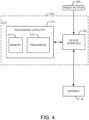
- the C/C 160 may include processing circuitry 210, as shown in FIG. 4 .
- the processing circuitry 210 that may be configured to perform data processing, control function execution and/or other processing and management services according to an example embodiment of the present invention.
- the processing circuitry 210 may be embodied as a chip or chip set.
- the processing circuitry 210 may comprise one or more physical packages (e.g., chips) including materials, components and/or wires on a structural assembly (e.g., a baseboard).
- the structural assembly may provide physical strength, conservation of size, and/or limitation of electrical interaction for component circuitry included thereon.
- the processing circuitry 210 may therefore, in some cases, be configured to implement an embodiment of the present invention on a single chip or as a single "system on a chip.” As such, in some cases, a chip or chipset may constitute means for performing one or more operations for providing the functionalities described herein.
- the processing circuitry 210 may include one or more instances of a processor 212 and memory 214 that may be in communication with or otherwise control a device interface 220.
- the processing circuitry 210 may be embodied as a circuit chip (e.g., an integrated circuit chip) configured (e.g., with hardware, software or a combination of hardware and software) to perform operations described herein.
- the processing circuitry 210 may communicate with internal electronic components of the first and second watering computers 120 and 122, the first or second sensors 140 and 142 and/or the robotic rover 15, and enable communication externally with other components.
- the device interface 220 may include one or more interface mechanisms for enabling communication with other devices via the gateway 40.
- the device interface 220 may be any means such as a device or circuitry embodied in either hardware, or a combination of hardware and software that is configured to receive and/or transmit data from/to the gateway 40 by virtue of the device interface 220 being capable of sending and receiving messages via the gateway 40.
- the device interface 220 may provide interfaces for communication of components of or external to the system 10 via the gateway 40.
- the device interface 220 may further interface with a sensor (e.g., a temperature sensor, a pH sensor, a light sensor, a moisture sensor and/or the like) to obtain sensor data for communication to other devices (e.g., the watering computers). Meanwhile, if the C/C 160 is for a watering computer, the device interface 220 may provide interfaces to other onboard components (e.g., a user interface including lights and a main button as described below).
- a sensor e.g., a temperature sensor, a pH sensor, a light sensor, a moisture sensor and/or the like
- other onboard components e.g., a user interface including lights and a main button as described below.
- the processor 212 may be embodied in a number of different ways.
- the processor 212 may be embodied as various processing means such as one or more of a microprocessor or other processing element, a coprocessor, a controller or various other computing or processing devices including integrated circuits such as, for example, an ASIC (application specific integrated circuit), an FPGA (field programmable gate array), or the like.
- the processor 212 may be configured to execute instructions stored in the memory 214 or otherwise accessible to the processor 212.
- the processor 212 may represent an entity (e.g., physically embodied in circuitry - in the form of processing circuitry 210) capable of performing operations according to embodiments of the present invention while configured accordingly.
- the processor 212 when the processor 212 is embodied as an ASIC, FPGA or the like, the processor 212 may be specifically configured hardware for conducting the operations described herein.
- the processor 212 when the processor 212 is embodied as an executor of software instructions, the instructions may specifically configure the processor 212 to perform the operations described herein.
- the processor 212 may be embodied as, include or otherwise control the C/C 160.
- the processor 212 may be said to cause each of the operations described in connection with the C/C 160 (and corresponding distributed component with which the C/C 160 is associated) by directing the C/C 160 to undertake the corresponding functionalities responsive to execution of instructions or algorithms configuring the processor 212 (or processing circuitry 210) accordingly.
- the C/C 160 of the sensors may be configured to detect environmental parameters (e.g., sensor data) and report the sensor data via the first wireless link to the gateway 40 (and ultimately to the app on the user terminal 50 or to storage in the cloud via the network 60).
- the C/C 160 of the sensors may be configured to determine a difference between a prior set of sensor data (e.g., the magnitude of a previous sensor measurement) and the current set of sensor data (e.g., the magnitude of a most recent sensor measurement). The amount of difference may then be used to determine whether or not the sensor will report the current set of sensor data. If the difference is small (e.g., less than a threshold amount) the sensor may not report the new value. However, if the difference is large enough (e.g., larger than the threshold amount), then the sensor may report the new value. As such, the C/C 160 of the sensors may be configured to perform battery conservation techniques relative to reporting of sensor data.
- the C/C 160 of the sensors may also be configured to otherwise report (or make a determination on whether to report based on the criteria discussed above) sensor data on a given schedule or responsive to certain activities or events.
- a trigger event e.g., temporal or action based trigger
- the C/C 160 of the sensor may make a determination of the current sensor data and decide whether or not to report the sensor data.
- the C/C 160 of the watering computers may be configured to control the operation of the valve 170 on the basis of schedule information stored locally in the memory 214 of the C/C 160.
- the C/C 160 of the watering computers may also allow modifications to the schedule, other programming operations, and/or the real-time taking of control over the position of the valve 170.
- the operator may be enabled to remotely monitor current valve 170 position and/or program settings and make modifications to either.
- the C/C 160 of the watering computers may be programmed to water when sensor data falling within or exceeding certain ranges or thresholds is received.
- the watering computers may be configured to open the valve 170 to deliver water to the sprinklers.
- the C/C 160 of the robotic rover 15 may be configured to control the travels and operations of the robotic rover 15. Moreover, the C/C 160 of the robotic rover 15 may allow the gateway 40 to grant user access to modification of the schedule of operations of the robotic rover 15 and/or to take real-time control over various operations of the robotic rover 15.
- the app at the user terminal 50 may be employed to coordinate and/or de-conflict watering schedules and mowing schedules. Additionally or alternatively, if the operator makes a modification to a schedule or takes real-time control of one or more components, the app at the user terminal 50 may provide alerts to indicate that the proposed changes to the schedule or current operations may be problematic, or may prevent the making of such changes.
- an alert may be provided to indicate that the robotic rover 15 should have its operations changed, or the opening of the valve 170 may be delayed.
- the electronic deployed components may further include a reset button 230 provided at a secure portion thereof.
- the reset button 230 may be provided in or near a battery compartment of the corresponding device.
- the reset button 230 may be used to insert a reset condition that may trigger different functionalities through the programming of the processing circuitry 210 for corresponding different situations and/or actuation methods. For example, a short press of the reset button 230 may cause the corresponding device to go into a pairing mode. Once in the pairing mode, the device may be detectable by the gateway 40 and/or other devices for a given period of time.
- the app on the user terminal 50 may be used to detect the device in pairing mode and, once detected, the app may also be used to pair the device to another device (e.g., of the first network - the deployed component network).
- the gateway 40 and the C/C 160 of the corresponding devices may then be capable of communication with each other on a continuous, event driven or scheduled basis via the first wireless link.
- the first sensor 140 may be configured to provide sensor data to the first watering computer 120 (e.g., via the gateway 40).
- the first sensor 140 may be paired with the first watering computer 120 via a setup procedure and communicate thereafter on a schedule or an activity/event driven basis.
- simple replacement or insertion of a battery to power up the device may be an additional or alternative method by which to initiate the pairing mode.
- a long press of the reset button 230 may result in returning the device to factory settings.
- contents of the memory 214 may be cleared or otherwise reset to initial settings or conditions.
- Other functions may also or alternatively be provided.
- some devices may have additional buttons or operable members.
- the first watering computer 120 may have a main button on a housing of the first watering computer 120 as described in greater detail below.
- Communication between the gateway 40 and the sensors or watering computers may occur for pairing purposes and to facilitate the operational activities for which the system 10 is ultimately configured.
- the operator may use the app at the user terminal 50 to connect to the gateway 40 and may be provided with one or more control console or interface screens that provide options for interacting with deployed components and/or for programming the deployed components.
- initial setup of the system may be facilitated by placing individual deployed components (either sequentially or simultaneously) in a pairing mode.
- the deployed components are then discoverable via the first wireless link and can be added to the first network. Once added to the first network, the deployed components are considered to be assets of the first network that can be interacted with/programmed and/or the like.
- the deployed components can then be paired with each other and configured for individual and/or cooperative functional performance.
- the first watering computer 120 may be paired with the second watering computer 122, with the robotic rover 15 and/or the first sensor 140.
- the operator may have options provided (e.g., via the app) to select instructions or scheduling options for intelligent irrigation.
- the first watering computer 120 may therefore be instructed regarding the specific stimuli that may be received from the first sensor 140 to trigger opening the valve 170.
- the first watering computer 120 may be provided with (e.g., in the memory 214) a schedule or listing of event triggers which cause the first watering computer 120 to "ping" or otherwise reach out to the first sensor to initiate communication to receive sensor data. Based on the sensor data received (e.g., if certain threshold parameters are reached or not), the valve 170 may be opened.
- the app on the user terminal 50 may ensure that scheduling of mowing during watering (or vice versa) is not possible. However, given that the operator can take control of the watering computers and/or the robotic rover 15 to initiate operations, the app on the user terminal 50 may further prevent any attempts to initiate operations of watering computers or the robotic rover 15 in real-time when the other is also operating in the same area.
- watering schedules or operations can be coordinated to manage or prevent under-pressure situations.
- the first and second watering computers 120 and 122 are connected to the splitter 125, as shown in FIG. 3 , it may be possible for water pressure to be insufficient to effectively charge both the first water line 110 and the second water line 112 at the same time.
- operations of one may be communicated to the other (e.g., via the gateway 40) so that the second watering computer 122 will not open its valve 170, while the first watering computer 120 is currently engaged in watering operations.
- the deployed components of various example embodiments may be adaptive to various conditions or situations.
- the adaptive nature of the deployed components may be provided as a programmable feature, where the operator can use the user terminal 50 to program specific adaptive behaviors that are adjustable parameters, relationships or responses.
- the programmable feature should be understood to be remotely programmable (i.e., programmable from the app and/or the user terminal 50 remote from the component being programmed) via the gateway 40.
- the adaptive nature of the deployed components may be provided as a default feature.
- the adaptive capabilities of the deployed components may either be dependent upon connectivity (e.g., connectivity dependent) for remote programming, or may be connectivity independent (e.g., default programming that exists or is instituted when there is no connectivity or responsive to a loss of connectivity.
- battery power levels may be communicated to the gateway 40 and signal strength values relating to communication with the sensors and/or watering computers may also be determined at the gateway 40. This information (along with sensor data) may be provided to the app at the user terminal 50 to alert the operator when battery power is low, or signal strengths are low. Battery replacement and/or sensor repositioning may then be undertaken to improve the situation.
- the sensor may also adaptively respond to its surroundings to trigger reports.
- the water computer may attempt to ping the sensor via the gateway 40 to trigger a report of sensor data.
- the sensor may be configured (e.g., via the C/C 160) to determine the amount of change in the requested parameter before deciding whether to respond to the ping.
- a change of at least a specific amount or percentage may be required before the sensor will report sensor data via wireless transmission. Since wireless transmission consumes more power than internal operation (e.g., to determine the amount of change and current sensor data), by saving several transmission cycles when there is little data change, battery life can be substantially extended.
- the last value received may be substituted and communicated to the operator (e.g., via the app).
- the operator can wake up the watering computers and/or sensors by sending a ping or wake up message to either component via the app.
- the wake up message may be used to see if the devices are still reacting and active, or to request specific data from or initiate actions at such components in real time.
- the operator can send a wakeup, or setup signal to have the corresponding device beacon for at least a predetermined amount of time (e.g., three minutes).
- the devices may be positioned and the operator may check the app to see what signal strength is detected by the gateway 40. The operator can therefore position the devices in real time and make sure that the position in which a device is currently located is a good location from the perspective of its ability to communicate with the gateway 40.
- one or more of the deployed components may further include frost warning capability.
- frost warning capability since the watering computers typically have pressurized water proximate to the valve 170, it should be appreciated that freezing of water in the body of the watering computers may be destructive to the valve 170. Accordingly, the C/C 160 of one or more components (especially the watering computers) may be configured to identify situations where there is a potential for frost that may damage the watering computers. In some embodiments, if the temperature reaches a predetermined threshold distance from the freezing point (e.g., 5 degrees C, or 10 degrees F), an alert may be issued (e.g., through the app at the user terminal 50) to warn the operator that the watering computer (and/or sensors) should be brought in to avoid damage.
- a predetermined threshold distance from the freezing point e.g., 5 degrees C, or 10 degrees F
- the predetermined threshold may be a factory setting, or may be set by the operator. However, in either case, the ability to identify a present temperature condition to alert the operator of a possible frost event is another example of how the deployed components may be configured (by operator program or by default) to be adaptive relative to their surroundings and/or circumstances.
- the adaptability of the deployed components relates to the inability to connect to the first network or a loss of connection to the first network.
- the watering schedules could be maintained in the cloud, on the user terminal 50 or elsewhere, in some cases, the watering schedule (or at least a portion thereof) may be stored locally at the watering computers.
- the memory 214 may be configured to record at least the last water schedule information employed.
- the first and second watering computers 120 and 122 may each store at least the information indicative of their respective last watering schedules.
- each of the first and second watering computers 120 and 122 will continue to water on the previously provided schedule.
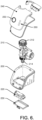
- the watering computer may include a housing body 200 that houses a valve assembly 210 (which includes valve 170) and a battery pack 220 (e.g., P/S 150).
- the battery pack 220 may be provided in a battery compartment that is accessible via the battery compartment door 230.
- the valve assembly 210 may include a tap adapter 212 configured to interface with a spigot or tap of a pressurized water system (e.g., water source 100) and provide an input port for the valve assembly 210.
- a pressurized water system e.g., water source 100
- An output port of the valve assembly 210 may include a hose adapter 214, which may include or be embodied as a quick coupler to/from which a hose can easily be connected/disconnected.
- the housing body 200 may mate with a cover plate 240, which may be a single plate or made of multiple plates.
- the cover plate 240 may include a single main button 250, which may be the only physically embodied operable member associated with the user interface of the watering computer.
- the other physical portion of the user interface that is local to the watering computer may be a light assembly 260, which may include one or more LEDs.
- the main button 250 may have at least two functions (and in some cases only two functions).
- the main button 250 may be operated to manually shift the valve assembly 210 so that the valve 170 is alternately opened or closed (i.e., changed from its current condition to the opposite condition) and/or to trigger a display of status information via the light assembly 260.
- pressing the main button 250 will cause the light assembly 260 to show the current state of the watering computer for a predetermined amount of time (e.g., 20 seconds). After the predetermined amount of time has passed, the watering computer may shut off the light assembly 260 and the valve 170 may remain closed.
- the valve 170 may be opened.
- the valve 170 may remain open for the same amount of time that the operator defined for valve opening via the app the last time the operator used the app.
- the time for which the valve 170 remains opened is adaptive insofar as the opening time is based on programmed settings used the last time the operator interacted with the app.
- FIG. 7 illustrates a perspective view of a sensor 300 according to an example embodiment.
- the sensor 300 may include a base portion 310, which may be inserted into the ground.
- the base portion 310 may be tapered to facilitate piercing the ground for placement therein.
- the base portion 310 may also house sensor portions for interfacing with the ground to detect temperature, pH, moisture, and/or the like.
- the base portion 310 may support a head portion 320 inside which a battery compartment may be provided for supporting the battery pack that powers the sensor 300.
- the head portion 320 may also house communications and/or processing equipment (e.g., the C/C 160 and any antenna(s) and/or the like). In some cases, the head portion 320 may also house a light sensor or other sensing equipment.
- a system of an example embodiment may include sensor equipment having one or more sensors disposed on a parcel of land, watering equipment disposed on the parcel and configured to selectively apply water to the parcel, and a gateway configured to provide for communication with the sensor equipment and the watering equipment.
- the gateway may interface between a first network and a second network.
- the first network may include at least the watering equipment and the sensor equipment.
- An operator may be enabled to wirelessly communicate with the gateway via the second network.
- At least one component of the watering equipment or the sensor equipment may be an adaptive component.
- the system may further include a robotic rover that is also adaptively configured.
- the watering equipment may include a watering computer including a valve assembly.
- the watering computer may be operably coupled to a water source and a water line such that the valve assembly is operable, by the watering computer, to alternately couple the water source to and isolate the water source from the water line.
- the sensor equipment may include a sensor paired with the watering computer via the gateway to communicate sensor data to the watering computer.
- the watering computer may be adaptive as a programmable feature such that the operator is enabled to program a specific adaptive behavior as an adjustable parameter, relationship or response.
- the watering computer may be adaptively configured to respond to temperature by receiving temperature data and providing an alert to the operator responsive to the temperature data being within a predetermined amount of a freezing point.
- the watering computer may be adaptively configured to respond to the sensor data by operating the valve assembly based on an indication that the sensor data corresponds to an operator selected trigger.
- the watering computer may be adaptively configured to respond to a loss of connectivity to the gateway or the sensor by employing a previously programmed watering schedule.
- the watering computer may be adaptive as a default feature such that the watering computer employs a default parameter, relationship or response responsive to an absence of communication from the gateway.
- the watering computer may be configured to employ a last sensor data parameter responsive to not receiving a response to a request for sensor data from the sensor.
- the watering computer may be configured to erase memory and restore default settings responsive to a reset condition.
- the watering computer may be configured to enter a pairing mode responsive to a reset condition.
- the sensor may be configured to adaptively report sensor data to the gateway.
- the sensor may be configured to adaptively report sensor data to the gateway by determining whether a current reading is different from a last reading by greater than a threshold amount, and may only transmit the current reading to the gateway responsive to the current reading being different from the last reading by greater than the threshold amount.
- the second network may include a user terminal via which the operator provides a watering schedule or parameters for initiating watering based on sensor data to the watering computer.
- the second network may include an in-home access point that is wirelessly connectable to the gateway, and a first wireless link that is employed on the first network may be different than a second wireless link employed on the second network.
- the operator may be enabled to receive battery status information or signal strength information relating to the watering equipment or the sensor equipment.
- the watering computer may include a main button and a light assembly, and the main button may be manually operable to display status via the light assembly or to actuate the valve assembly.
- the operator may be enabled to interface with the watering equipment and the sensor equipment via the gateway to pair devices of the watering equipment with corresponding devices of the sensor equipment.
- the operator may be enabled to interface with the watering equipment, the robotic rover and the sensor equipment via the gateway to coordinate watering and mowing schedules.
- the operator may be notified via the gateway when one of the watering equipment or the robotic rover is actuated via the gateway while the other of the watering equipment or the robotic rover is operating in a same area.
Claims (10)
- Système d'arrosage (10) doté d'un composant adaptatif comprenant :un équipement de capteur (30) comportant un ou plusieurs capteurs (140, 142, 300) disposés sur une parcelle d'équipement d'arrosage terrestre (20) disposé sur la parcelle et configuré pour appliquer sélectivement de l'eau à la parcelle ; etune passerelle (40) configurée pour fournir une communication avec l'équipement d'arrosage (20), dans lequella passerelle (40) constitue une interface entre un premier réseau comprenant au moins l'équipement d'arrosage (20) et l'équipement de capteur (30) et un second réseau par l'intermédiaire duquel un opérateur est activé pour communiquer sans fil avec la passerelle (40) ; etau moins un composant de l'équipement d'arrosage (20) et de l'équipement de capteur (30) est un composant adaptatif,dans lequel les composants du système d'arrosage sont configurés aux conditions ou stimuli actuels qui sont présents dans leur environnement,dans lequel le système d'arrosage (10) utilise un réseau de communication pour collecter des informations sur des conditions de croissance de plante à partir de l'équipement de capteur pour association des informations avec les zones à partir desquelles les informations ont été collectées,la passerelle fournit en outre une communication avec l'équipement de capteur (30) ;et dans lequel, lorsque la connectivité internet est possible, le système d'arrosage est employé pour corréler des conditions de croissance souhaitables à une espèce de plante identifiée sur la base d'informations stockées associées à chaque espèce de plante d'une base de données ou d'une ressource en ligne,en outre, le système d'arrosage (10) emploie une combinaison d'atouts fixes et mobiles qui collectent des données qui se rapportent à des segments spécifiques, dans lequel un atout mobile est un véhicule télécommandé robotisé (15),dans lequel le système d'arrosage (10) effectue des opérations connexes à l'aide du véhicule télécommandé robotisé (15),caractérisé en ce quedes segments spécifiques de la parcelle qui correspondent à des zones différentes respectives présentent différents types de plantes dans celui-ci,le ou les capteurs (140, 142, 300) étant insérés dans un sol pour surveiller le sol ou d'autres conditions de croissance collectant des données qui se rapportent à des segments spécifiques de la parcelle qui correspondent à des zones différentes respectives.
- Système d'arrosage (10) doté d'un composant adaptatif selon la revendication 1, dans lequel la passerelle (40) a une connexion filaire ou sans fil à un point d'accès (45), qui peut être connecté directement ou indirectement à un terminal utilisateur (50),dans lequel le ou les capteurs (140, 142, 300) rapportent les données de capteur à une application sur le terminal utilisateur (50) de sorte qu'un utilisateur peut voir les paramètres de condition de croissance par rapport aux diverses zones etdans lequel le terminal utilisateur (50) permet de programmer le fonctionnement des composants du système d'arrosage en conséquence par rapport à un maintien des conditions de croissance souhaitées pour la zone correspondante, les conditions de croissance sont l'un quelconque ou la totalité du niveau d'humidité, de la température, du niveau d'éclairage, du pH.
- Système d'arrosage (10) doté d'un composant adaptatif selon la revendication 2, dans lequel le véhicule télécommandé robotisé (15) est configuré de manière adaptative.
- Système d'arrosage (10) doté d'un composant adaptatif selon la revendication 1, la connexion à un contenu sur internet permet à un contenu pédagogique d'être intégré au fonctionnement du système d'arrosage.
- Système d'arrosage (10) doté d'un composant adaptatif selon l'une quelconque des revendications 1 à 4, dans lequel l'équipement d'arrosage (20) comprend un ordinateur d'arrosage (120, 122) comportant un ensemble soupape (210), l'ordinateur d'arrosage (120, 122) étant couplé de manière fonctionnelle à une source d'eau (100) et une conduite d'eau (110, 112) de telle sorte que l'ensemble soupape (210) peut être mis en fonctionnement par l'ordinateur d'arrosage (120, 122) pour coupler alternativement la source d'eau (100) et isoler la source d'eau (100) de la ligne d'eau (110, 112).
- Système d'arrosage (10) doté d'un composant adaptatif selon la revendication 5, dans lequel l'ordinateur d'arrosage (120, 122) comprend un bouton principal (250) et un ensemble lumière (260), et dans lequel le bouton principal (250) est opérable manuellement pour afficher l'état par l'intermédiaire de l'ensemble lumière (260) ou actionner l'ensemble soupape (210).
- Système d'arrosage (10) doté d'un composant adaptatif selon la revendication 5, dans lequel l'équipement de capteur (30) comprend un capteur apparié à l'ordinateur d'arrosage (120, 122) par l'intermédiaire de la passerelle (40) pour communiquer des données de capteur à l'ordinateur d'arrosage (120, 122).
- Système d'arrosage (10) doté d'un composant adaptatif selon la revendication 5, dans lequel le capteur comporte : une partie de base (310) qui est insérée dans la terre et loge une partie de capteur pour l'interfaçage avec la terre pour détecter au moins l'un parmi la température, le pH et l'humidité ; et une partie de tête (320) qui est supportée par la partie de base, à l'intérieur de la partie de tête, un compartiment de batterie est prévu pour supporter le bloc-batterie qui alimente le capteur.
- Système d'arrosage (10) doté d'un composant adaptatif selon la revendication 4, dans lequel le remplacement ou l'insertion d'un bloc-batterie pour alimenter le capteur lance le mode d'appariement entre le capteur et un ordinateur d'arrosage correspondant.
- Système d'arrosage (10) doté d'un composant adaptatif selon la revendication 3, dans lequel l'opérateur est notifié par l'intermédiaire de la passerelle (40) lorsque l'un de l'équipement d'arrosage (20) ou du véhicule télécommandé robotisé (15) est actionné par l'intermédiaire de la passerelle (40) lorsque l'autre de l'équipement d'arrosage (20) ou du véhicule télécommandé robotisé (15) fonctionne dans une même zone.
Priority Applications (2)
| Application Number | Priority Date | Filing Date | Title |
|---|---|---|---|
| EP20150107.9A EP3729957B1 (fr) | 2015-04-10 | 2015-04-10 | Système d'arrosage muni de composants adaptatifs |
| FIEP20150107.9T FI3729957T3 (fi) | 2015-04-10 | 2015-04-10 | Adaptiivisia komponentteja sisältävä kastelujärjestelmä |
Applications Claiming Priority (3)
| Application Number | Priority Date | Filing Date | Title |
|---|---|---|---|
| EP20150107.9A EP3729957B1 (fr) | 2015-04-10 | 2015-04-10 | Système d'arrosage muni de composants adaptatifs |
| PCT/EP2015/057845 WO2016162085A1 (fr) | 2015-04-10 | 2015-04-10 | Système d'arrosage muni de composants adaptatifs |
| EP15716031.8A EP3280250B1 (fr) | 2015-04-10 | 2015-04-10 | Système d'arrosage muni de composants adaptatifs |
Related Parent Applications (3)
| Application Number | Title | Priority Date | Filing Date |
|---|---|---|---|
| PCT/EP2015/057845 Previously-Filed-Application WO2016162085A1 (fr) | 2015-04-10 | 2015-04-10 | Système d'arrosage muni de composants adaptatifs |
| EP15716031.8A Division-Into EP3280250B1 (fr) | 2015-04-10 | 2015-04-10 | Système d'arrosage muni de composants adaptatifs |
| EP15716031.8A Division EP3280250B1 (fr) | 2015-04-10 | 2015-04-10 | Système d'arrosage muni de composants adaptatifs |
Publications (2)
| Publication Number | Publication Date |
|---|---|
| EP3729957A1 EP3729957A1 (fr) | 2020-10-28 |
| EP3729957B1 true EP3729957B1 (fr) | 2024-03-13 |
Family
ID=52829089
Family Applications (2)
| Application Number | Title | Priority Date | Filing Date |
|---|---|---|---|
| EP15716031.8A Active EP3280250B1 (fr) | 2015-04-10 | 2015-04-10 | Système d'arrosage muni de composants adaptatifs |
| EP20150107.9A Active EP3729957B1 (fr) | 2015-04-10 | 2015-04-10 | Système d'arrosage muni de composants adaptatifs |
Family Applications Before (1)
| Application Number | Title | Priority Date | Filing Date |
|---|---|---|---|
| EP15716031.8A Active EP3280250B1 (fr) | 2015-04-10 | 2015-04-10 | Système d'arrosage muni de composants adaptatifs |
Country Status (9)
| Country | Link |
|---|---|
| US (2) | US11039583B2 (fr) |
| EP (2) | EP3280250B1 (fr) |
| JP (1) | JP6480597B2 (fr) |
| CN (6) | CN107438363B (fr) |
| AU (1) | AU2015390450B2 (fr) |
| CA (3) | CA2977327C (fr) |
| FI (1) | FI3729957T3 (fr) |
| TW (2) | TWI769474B (fr) |
| WO (1) | WO2016162085A1 (fr) |
Families Citing this family (18)
| Publication number | Priority date | Publication date | Assignee | Title |
|---|---|---|---|---|
| GB2593987B (en) * | 2015-05-18 | 2022-02-09 | Exel Industries Sa | Garden watering controllers |
| GB2538504C2 (en) * | 2015-05-18 | 2024-02-28 | Exel Industries Sa | Garden watering controllers |
| CN106899497A (zh) * | 2015-12-18 | 2017-06-27 | 阿基米德自动控制公司 | 智能多通道无线数据获取网关 |
| CN107145084A (zh) * | 2017-04-21 | 2017-09-08 | 句容市宝启电子科技有限公司 | 园林绿化养护控制系统 |
| JOP20190172A1 (ar) * | 2017-06-14 | 2019-07-09 | Grow Solutions Tech Llc | وسائل، أنظمة، وطرق لتوفير واستخدام واحد أو أكثر من الصمامات بحجيرة نمو خط تجميع |
| CN108199954B (zh) * | 2018-01-23 | 2019-01-08 | 南京万荣立体绿化工程有限公司 | 灌溉智能监测系统 |
| CN108153269B (zh) * | 2018-02-05 | 2019-10-01 | 成都数智凌云科技有限公司 | 面向植物智能灌溉的控制方法及系统 |
| US10512034B2 (en) * | 2018-02-07 | 2019-12-17 | Blackberry Limited | Sensor provisioning in wireless sensor networks |
| DE102018108513A1 (de) | 2018-04-10 | 2019-10-10 | Alfred Kärcher SE & Co. KG | System zur Bewässerung von Grünflächen |
| WO2020112401A2 (fr) | 2018-11-28 | 2020-06-04 | The Toro Company | Systèmes, véhicules autonomes de traitement de surface de sol et procédés |
| TWI697275B (zh) * | 2019-06-20 | 2020-07-01 | 欣大園藝噴水工具有限公司 | 具調整顯示面板視角之園藝水管啟閉定時器 |
| TWI693881B (zh) * | 2019-07-31 | 2020-05-21 | 南開科技大學 | 應用物聯網於自動澆水之濕度監控系統 |
| EP4072269B1 (fr) | 2019-12-11 | 2023-06-21 | Husqvarna Ab | Système pour faire fonctionner un dispositif de commande d'équipement de jardin |
| CN111319043B (zh) * | 2020-02-20 | 2022-03-22 | 达闼机器人有限公司 | 机器人的控制方法、装置、存储介质和机器人 |
| CN114054245B (zh) * | 2020-07-30 | 2023-05-30 | 云米互联科技(广东)有限公司 | 智能花洒的控制方法、智能花洒及存储介质 |
| CN112221740A (zh) * | 2020-09-30 | 2021-01-15 | 北京小米移动软件有限公司 | 智能地埋喷头及喷洒方法 |
| EP3994977A1 (fr) | 2020-11-06 | 2022-05-11 | Husqvarna Ab | Robot d'arrosage et système d'arrosage associé |
| CN113296433A (zh) * | 2021-04-28 | 2021-08-24 | 成都秦川物联网科技股份有限公司 | 一种单片机复位方法 |
Family Cites Families (134)
| Publication number | Priority date | Publication date | Assignee | Title |
|---|---|---|---|---|
| US4176395A (en) * | 1977-11-16 | 1979-11-27 | Clemar Manufacturing Corporation | Interactive irrigation control system |
| US5251153A (en) * | 1988-09-28 | 1993-10-05 | Solatrol, Inc. | Flexibly programmable irrigation system controller |
| US5740031A (en) * | 1995-09-07 | 1998-04-14 | Smart Rain Corp. Inc. | Control system for the irrigation of watering stations |
| US6437692B1 (en) * | 1998-06-22 | 2002-08-20 | Statsignal Systems, Inc. | System and method for monitoring and controlling remote devices |
| IL130791A0 (en) * | 1999-07-04 | 2001-01-28 | Arad Com Inc | Irrigation method and system |
| US6611738B2 (en) * | 1999-07-12 | 2003-08-26 | Bryan J. Ruffner | Multifunctional mobile appliance |
| US6377181B1 (en) * | 2001-02-05 | 2002-04-23 | Dryvit Systems, Inc. | Method and apparatus for moisture detection in exterior sheathing of residential and commercial buildings |
| JP2002233255A (ja) * | 2001-02-07 | 2002-08-20 | Sekisui Plant Systems Co Ltd | 散水システム |
| US6823239B2 (en) * | 2001-11-05 | 2004-11-23 | Rain Master Irrigation Systems, Inc. | Internet-enabled central irrigation control |
| US20040015270A1 (en) * | 2002-03-21 | 2004-01-22 | Addink John W. | Interactive irrigation system |
| WO2003099454A2 (fr) * | 2002-05-22 | 2003-12-04 | University Of Florida | Procede et systeme de commande automatique pour l'irrigation |
| US7146254B1 (en) | 2002-07-05 | 2006-12-05 | Matsushita Electric Works, Ltd. | Systems and methods for optimizing the efficiency of a watering system through use of a computer network |
| US6782311B2 (en) * | 2002-08-10 | 2004-08-24 | Jame E. Barlow | Remotely controlled irrigation timer with fault detection |
| WO2004052560A2 (fr) * | 2002-12-10 | 2004-06-24 | Et Water Systems, Llc | Systeme d'irrigation |
| CN100342776C (zh) * | 2003-04-22 | 2007-10-17 | 楼信用 | 一种自动间歇轮流灌溉控制方法及其装置 |
| US7058478B2 (en) * | 2003-04-25 | 2006-06-06 | George Alexanian | Irrigation controller water management with temperature budgeting |
| US7844368B2 (en) * | 2003-04-25 | 2010-11-30 | George Alexanian | Irrigation water conservation with temperature budgeting and time of use technology |
| US20050125083A1 (en) | 2003-11-10 | 2005-06-09 | Kiko Frederick J. | Automation apparatus and methods |
| US7844367B2 (en) * | 2003-12-23 | 2010-11-30 | Rain Bird Corporation | Code replacement for irrigation controllers |
| US7097113B2 (en) * | 2004-01-20 | 2006-08-29 | Norman Ivans | Irrigation unit including a power generator |
| US20050187665A1 (en) * | 2004-02-23 | 2005-08-25 | International Business Machines Corporation | Automatic yard moisture control system |
| US7142107B2 (en) | 2004-05-27 | 2006-11-28 | Lawrence Kates | Wireless sensor unit |
| WO2006004985A1 (fr) | 2004-06-30 | 2006-01-12 | Great Stuff, Inc. | Systeme a faible puissance pour controle sans fil d'un environnement, et controle d'irrigation |
| US7789321B2 (en) * | 2004-09-07 | 2010-09-07 | Digital Sun, Inc. | Wireless sprinkler control |
| US7412303B1 (en) | 2005-11-29 | 2008-08-12 | Hunter Industries, Inc. | Evapotranspiration unit for re-programming an irrigation controller |
| US7590471B2 (en) * | 2004-12-02 | 2009-09-15 | Sterling Investments Lc | Intelligent sprinkler irrigation system |
| US20070016334A1 (en) * | 2005-06-30 | 2007-01-18 | Smith Brian J | Method and system for transmitting and utilizing forecast meteorological data for irrigation controllers |
| US8359288B1 (en) * | 2005-12-30 | 2013-01-22 | Dp Technologies, Inc. | Method and apparatus to utilize sensor, monitor, device (SMD) data based on location |
| US20130099022A9 (en) * | 2006-02-10 | 2013-04-25 | Doug Palmer | Electronic Irrigation System Software |
| US8516087B2 (en) | 2006-02-14 | 2013-08-20 | At&T Intellectual Property I, L.P. | Home automation system and method |
| US9144204B2 (en) | 2006-06-20 | 2015-09-29 | Rain Bird Corporation | User interface for a sensor-based interface device for interrupting an irrigation controller |
| US7949433B2 (en) * | 2006-06-20 | 2011-05-24 | Rain Bird Corporation | Sensor device for interrupting irrigation |
| CN200969804Y (zh) * | 2006-07-13 | 2007-11-07 | 河北农业大学 | 一种手机短信无线遥控的浇灌装置 |
| US8055389B2 (en) | 2006-09-01 | 2011-11-08 | Dig Corporation | Method and apparatus for controlling irrigation |
| CN101155090A (zh) * | 2006-09-29 | 2008-04-02 | 湖南大学 | 基于无线传感器网络的农业节水灌溉系统与方法 |
| US7810515B2 (en) | 2007-03-14 | 2010-10-12 | Melnor, Inc. | Smart water timer |
| CN201004879Y (zh) * | 2007-03-30 | 2008-01-16 | 上海市杨浦区控江二村小学 | 一种浇水装置 |
| ES2311409A1 (es) * | 2007-07-13 | 2009-02-01 | Samcla-Esic, S.L. | Sistema de riego automatizado, remoto y centralizado. |
| CN101389107B (zh) | 2007-09-10 | 2012-04-18 | 中兴通讯股份有限公司 | 一种大话务模拟测试系统和方法 |
| CN100583178C (zh) | 2007-10-16 | 2010-01-20 | 浙江大学 | 基于无线传感器网络的茶园微域监控方法与系统 |
| US8024075B2 (en) | 2007-12-05 | 2011-09-20 | Daniel Joseph Fekete | System and method for wireless irrigation utilizing a centralized control server and field module matrix |
| WO2009100060A1 (fr) * | 2008-02-04 | 2009-08-13 | Cyber-Rain, Inc. | Systèmes et procédés d'irrigation sensibles aux conditions météorologiques |
| US20120037725A1 (en) * | 2008-03-27 | 2012-02-16 | Orion Energy Systems, Inc. | Sprinkler control systems and methods |
| TR200805998A2 (tr) | 2008-08-12 | 2009-12-21 | Kodalfa B�Lg� Ve �Let���M Teknoloj�Ler� Sanay� Ve T�Caret A.�. | Seralar için uzaktan kablosuz iklim gözlemleme ve kontrol sistemi |
| US9026315B2 (en) * | 2010-10-13 | 2015-05-05 | Deere & Company | Apparatus for machine coordination which maintains line-of-site contact |
| WO2010068950A2 (fr) | 2008-12-12 | 2010-06-17 | Blanchard Ron N | Appareil de commande d’irrigation, système et procédé |
| US20100179701A1 (en) | 2009-01-13 | 2010-07-15 | At&T Intellectual Property I, L.P. | Irrigation system with wireless control |
| US8028470B2 (en) | 2009-04-21 | 2011-10-04 | Deere & Company | Robotic watering unit |
| AU2010249499B2 (en) * | 2009-05-22 | 2015-01-29 | Mueller International Llc | Infrastructure monitoring devices, systems, and methods |
| CN101569281B (zh) * | 2009-05-26 | 2013-06-12 | 重庆大学 | 露天植物浇灌控制系统及其控制方法 |
| CN201448993U (zh) * | 2009-06-04 | 2010-05-05 | 广东万和新电气股份有限公司 | 带防冻警示装置的燃气热水器 |
| US20110210187A1 (en) * | 2009-06-21 | 2011-09-01 | Anctechnology | Automatic Sprinkler and Irrigation System |
| AU2010276364B2 (en) | 2009-07-20 | 2016-11-10 | Samsung Electronics Co., Ltd. | Energy management system and method |
| CN201491576U (zh) * | 2009-08-19 | 2010-06-02 | 遵义群建塑胶制品有限公司 | 一种节水灌溉远程自动控制系统 |
| CN101990840A (zh) * | 2009-08-19 | 2011-03-30 | 遵义群建塑胶制品有限公司 | 一种节水灌溉系统的远程自动控制方法及控制系统 |
| CN101642039A (zh) | 2009-08-20 | 2010-02-10 | 杭州师范大学 | 智能浇花小车 |
| EP2336834A1 (fr) * | 2009-11-20 | 2011-06-22 | Zerogroup Holding OÜ | Procédé et système pour contrôler les conditions environnementales d'une entité |
| US8295979B2 (en) * | 2010-01-06 | 2012-10-23 | Deere & Company | Adaptive scheduling of a service robot |
| US8285460B2 (en) * | 2010-01-06 | 2012-10-09 | Deere & Company | Varying irrigation scheduling based on height of vegetation |
| US8862277B1 (en) | 2010-02-01 | 2014-10-14 | Green Badge, LLC | Automatic efficient irrigation threshold setting |
| CN101806925A (zh) * | 2010-03-05 | 2010-08-18 | 北京佳讯飞鸿电气股份有限公司 | 铁路接触网霜冻预测 |
| CN201752200U (zh) * | 2010-05-28 | 2011-03-02 | 上海艾美克电子有限公司 | Gsm群控无线太阳能土壤湿度控制自动灌溉系统 |
| US9192110B2 (en) * | 2010-08-11 | 2015-11-24 | The Toro Company | Central irrigation control system |
| CN101999306B (zh) | 2010-10-25 | 2015-04-08 | 赵致钧 | 可视可对讲多模式灌溉控制系统及方法 |
| CN102037888B (zh) * | 2010-10-28 | 2011-11-30 | 重庆市科学技术研究院 | 分布式网络自动灌溉控制系统及其灌溉控制方法 |
| US8948921B2 (en) * | 2010-11-22 | 2015-02-03 | Et Water Systems, Inc. | System and method for smart irrigation |
| US20120175425A1 (en) * | 2011-01-11 | 2012-07-12 | Harris Corporation | Systems and methods for controlling a sprinkler system based on sensor information |
| JP2012147753A (ja) * | 2011-01-21 | 2012-08-09 | Yonden Gijutsu Consultant:Kk | 植物生育施設用自動散水システム |
| US8554380B2 (en) | 2011-02-07 | 2013-10-08 | National Diversified Sales, Inc. | Weather based irrigation controller |
| US9301460B2 (en) | 2011-02-25 | 2016-04-05 | The Toro Company | Irrigation controller with weather station |
| ITMI20110803A1 (it) | 2011-05-10 | 2012-11-11 | Claber Spa | Impianto di irrigazione a controllo remoto. |
| US20130253713A1 (en) * | 2011-05-12 | 2013-09-26 | LSI Saco Technologies, Inc. | Method and System for Electric-Power Distribution and Irrigation Control |
| CN102788183A (zh) | 2011-05-17 | 2012-11-21 | 上海天净管业有限公司 | 水压自动调节水路保护系统 |
| US9703275B2 (en) | 2011-06-23 | 2017-07-11 | Rain Bird Corporation | Methods and systems for irrigation and climate control |
| CN102388791B (zh) * | 2011-08-02 | 2016-06-01 | 赵致钧 | 中心支轴式喷灌机控制系统及方法 |
| AU2012289857B2 (en) | 2011-08-04 | 2016-06-23 | Vivint, Inc | System automation via an alarm system |
| US9077183B2 (en) | 2011-09-06 | 2015-07-07 | Portland State University | Distributed low-power wireless monitoring |
| CN202232421U (zh) | 2011-09-08 | 2012-05-30 | 甘肃大禹节水集团股份有限公司 | 田间滴灌的ZigBee无线控制系统 |
| DE102011084594A1 (de) * | 2011-10-17 | 2013-04-18 | Robert Bosch Gmbh | Autonomes Arbeitsgerät |
| US20130110293A1 (en) * | 2011-10-31 | 2013-05-02 | Harald Illig | Remotely-controlled water sprinkling system and method |
| CN102506941A (zh) * | 2011-11-21 | 2012-06-20 | 苏州迪芬德物联网科技有限公司 | 无线监测传感器 |
| US8930032B2 (en) * | 2011-11-22 | 2015-01-06 | Zbs Technology, Llc | System and method for wireless irrigation control with a remote application |
| CN102550373A (zh) * | 2011-12-16 | 2012-07-11 | 西安瑞特快速制造工程研究有限公司 | 一种基于手机短信的智能灌溉控制系统及控制方法 |
| US9265204B2 (en) * | 2011-12-19 | 2016-02-23 | Younis Technologies, Inc. | Remotely sensing and adapting irrigation system |
| US9175869B2 (en) * | 2011-12-21 | 2015-11-03 | Lennox Industries Inc. | Uniform HVAC comfort across multiple systems |
| CN202419936U (zh) * | 2012-01-09 | 2012-09-05 | 广东万和新电气股份有限公司 | 具有防冻警报功能的燃气热水器 |
| CN102572721B (zh) | 2012-01-13 | 2014-08-13 | 中兴通讯股份有限公司 | 一种群组终端移动性管理方法、系统及设备 |
| FR2986653A1 (fr) | 2012-02-03 | 2013-08-09 | St Microelectronics Sa | Memoire volatile a consommation reduite |
| CN102566558B (zh) | 2012-02-21 | 2013-04-10 | 南京农业大学 | 基于Android平台的智能温室管理系统及其方法 |
| WO2014007729A1 (fr) * | 2012-07-05 | 2014-01-09 | Husqvarna Ab | Véhicule robotisé modulaire |
| US9538713B2 (en) * | 2012-07-13 | 2017-01-10 | The Toro Company | Modular irrigation controller |
| CN102771358A (zh) * | 2012-07-14 | 2012-11-14 | 成都生辉电子科技有限公司 | 基于plc的自动灌溉控制系统 |
| US9468162B2 (en) * | 2012-08-01 | 2016-10-18 | Rain Bird Corporation | Irrigation controller wireless network adapter and networked remote service |
| CN102845283B (zh) * | 2012-09-24 | 2014-05-28 | 王春晔 | 喷灌机的智能灌溉控制管理系统 |
| CN202857464U (zh) | 2012-09-28 | 2013-04-10 | 南京信息工程大学 | 一种庭院花草自动浇水控制装置 |
| CN202941233U (zh) * | 2012-11-10 | 2013-05-22 | 西安扩力机电科技有限公司 | 一种基于专家系统的农田自动按需灌溉装置 |
| CN103070057A (zh) | 2012-12-13 | 2013-05-01 | 宁波大叶园林工业有限公司 | 一种智能摇摆喷水器 |
| AU2013204337A1 (en) | 2013-01-09 | 2014-07-24 | Lsi Industries, Inc. | Method and System for Electric-Power Distribution and Irrigation Control |
| CN203087142U (zh) * | 2013-02-05 | 2013-07-31 | 保定丰霸现代农业设施有限公司 | 中心支轴式喷灌机的远程智能化控制系统 |
| US9380750B2 (en) | 2013-02-08 | 2016-07-05 | Yuan-Mei Corp. | Automatic water sprinkler regulator |
| US20140236868A1 (en) * | 2013-02-15 | 2014-08-21 | Banyan Water, Inc. | System and method for automated, range-based irrigation |
| ES2659773T3 (es) | 2013-03-15 | 2018-03-19 | Vivint, Inc | Uso de un panel de control como un punto de acceso inalámbrico |
| CN203148876U (zh) | 2013-04-09 | 2013-08-21 | 沈序珍 | 手提式土壤湿度自动检测器 |
| US20150057817A1 (en) | 2013-07-01 | 2015-02-26 | Skydrop, Llc | Irrigation protocols when connection to a network is lost for an extended period |
| EP3033654B1 (fr) | 2013-08-16 | 2019-09-18 | Husqvarna AB | Système intelligent de traitement de sols |
| CA2921316C (fr) | 2013-08-16 | 2018-11-06 | Husqvarna Ab | Systeme intelligent de gestion de terrains incorporant un rover robotise |
| AU2014101142A4 (en) * | 2013-09-13 | 2014-10-16 | Oliver, Ian James | Plant profile watering system |
| CN203501580U (zh) * | 2013-10-15 | 2014-03-26 | 山东雅士股份有限公司 | 一种风冷热泵型冷水机组运行防冻保护装置 |
| CN103548647A (zh) * | 2013-11-04 | 2014-02-05 | 东北林业大学 | 基于手机遥控的智能浇灌系统 |
| CN103718929A (zh) | 2013-12-25 | 2014-04-16 | 北海三大利电子科技有限公司 | 花园植物自动浇水系统 |
| CN103763423A (zh) * | 2014-01-28 | 2014-04-30 | 李宝来 | 实现智能灌溉的手机 |
| CN103875508B (zh) | 2014-03-11 | 2016-03-23 | 长安大学 | 一种手机蓝牙或pc机控制的智能浇花系统及其控制方法 |
| CN103871252B (zh) | 2014-03-17 | 2016-01-20 | 南京瑞伟铭交通科技有限公司 | 一种冰雪路面交通安全动态预警方法 |
| CN106462168B (zh) * | 2014-03-20 | 2021-07-13 | 麦乐诺尔股份有限公司 | 用于控制阀门的无线装置、系统和方法 |
| CN203872715U (zh) | 2014-04-25 | 2014-10-15 | 金陵科技学院 | 一种基于ZigBee技术的语音智能自动灌溉系统 |
| CN103999743A (zh) * | 2014-05-14 | 2014-08-27 | 杭州电子科技大学 | 一种基于无线物联网的智能浇灌系统 |
| CN104067909A (zh) * | 2014-07-09 | 2014-10-01 | 新疆赛维东方能源科技有限公司 | 一种灌溉节水控制器 |
| CN204062483U (zh) * | 2014-07-18 | 2014-12-31 | 天津舜天达天然气有限公司 | 一种天然气的冻堵处理装置 |
| CN204141852U (zh) * | 2014-08-11 | 2015-02-04 | 宁波帅康热水器有限公司 | 一种具有防冻报警功能的燃气热水器 |
| US9645584B2 (en) * | 2014-09-17 | 2017-05-09 | Honeywell International Inc. | Gas valve with electronic health monitoring |
| CN204070010U (zh) * | 2014-09-29 | 2015-01-07 | 四川省农业机械研究设计院 | 一种智能无线远程控制灌溉系统 |
| CN104429832A (zh) * | 2014-11-11 | 2015-03-25 | 陈志雄 | 基于智能移动终端的无线远程灌溉系统及方法 |
| US20160161940A1 (en) * | 2014-12-04 | 2016-06-09 | Yaakov S. MAX | Intelligent water emergency system |
| WO2016103071A1 (fr) | 2014-12-23 | 2016-06-30 | Husqvarna Ab | Contrôle et entretien d'un gazon par l'intermédiaire d'un véhicule robotique |
| WO2016112138A1 (fr) * | 2015-01-06 | 2016-07-14 | Skydrop Holdings, Llc | Capteur de débit d'irrigation |
| AU2016255777B2 (en) * | 2015-04-29 | 2021-01-21 | Climate Llc | Systems, methods, and devices for monitoring weather and field conditions |
| US10034421B2 (en) * | 2015-07-24 | 2018-07-31 | Irobot Corporation | Controlling robotic lawnmowers |
| AU2016401639B2 (en) * | 2016-04-08 | 2019-02-14 | Husqvarna Ab | Intelligent watering pump |
| JP6621935B2 (ja) * | 2016-04-08 | 2019-12-18 | ハスクバーナ・アーベー | インテリジェント散水システム |
| WO2018000922A1 (fr) * | 2016-06-30 | 2018-01-04 | Tti (Macao Commercial Offshore) Limited | Tondeuse à gazon autonome et système de navigation associé |
| AU2017245290B1 (en) * | 2016-11-02 | 2018-05-10 | The Yield Technology Solutions Pty Ltd | Controlling Agricultural Production Areas |
| US20190297798A1 (en) * | 2017-12-22 | 2019-10-03 | Michael R. Levine | Method and Apparatus for Networked Irrigation Controllers that Adjust Watering Schedules in Response to Rainfall |
| CN110338037A (zh) | 2019-08-09 | 2019-10-18 | 王志军 | 一种园林绿化灌溉供水装置 |
| US11314213B1 (en) * | 2021-06-15 | 2022-04-26 | Haber Technologies, Inc. | Autonomous crop drying, conditioning and storage management |
-
2015
- 2015-04-10 EP EP15716031.8A patent/EP3280250B1/fr active Active
- 2015-04-10 CN CN201580078652.XA patent/CN107438363B/zh active Active
- 2015-04-10 EP EP20150107.9A patent/EP3729957B1/fr active Active
- 2015-04-10 FI FIEP20150107.9T patent/FI3729957T3/fi not_active Application Discontinuation
- 2015-04-10 CA CA2977327A patent/CA2977327C/fr active Active
- 2015-04-10 JP JP2017550885A patent/JP6480597B2/ja active Active
- 2015-04-10 CN CN201811156024.0A patent/CN109006416A/zh active Pending
- 2015-04-10 CN CN201811155485.6A patent/CN109006415B/zh active Active
- 2015-04-10 CA CA3113013A patent/CA3113013C/fr active Active
- 2015-04-10 US US15/565,516 patent/US11039583B2/en active Active
- 2015-04-10 CN CN201811157103.3A patent/CN109006419B/zh active Active
- 2015-04-10 CN CN201811156428.XA patent/CN109006418B/zh active Active
- 2015-04-10 CA CA2990378A patent/CA2990378C/fr active Active
- 2015-04-10 WO PCT/EP2015/057845 patent/WO2016162085A1/fr active Application Filing
- 2015-04-10 AU AU2015390450A patent/AU2015390450B2/en active Active
- 2015-04-10 CN CN201811156047.1A patent/CN109006417B/zh active Active
-
2016
- 2016-04-01 TW TW109122804A patent/TWI769474B/zh active
- 2016-04-01 TW TW105110600A patent/TWI700987B/zh active
-
2021
- 2021-06-18 US US17/351,663 patent/US20210307265A1/en active Pending
Also Published As
| Publication number | Publication date |
|---|---|
| CN107438363B (zh) | 2018-09-28 |
| AU2015390450A1 (en) | 2017-08-31 |
| EP3280250B1 (fr) | 2022-11-30 |
| CN109006416A (zh) | 2018-12-18 |
| TW201635896A (zh) | 2016-10-16 |
| JP2018511323A (ja) | 2018-04-26 |
| CA3113013C (fr) | 2024-03-19 |
| CN109006419A (zh) | 2018-12-18 |
| EP3729957A1 (fr) | 2020-10-28 |
| CA2990378C (fr) | 2021-05-25 |
| CN109006415B (zh) | 2021-09-24 |
| TW202041143A (zh) | 2020-11-16 |
| CN109006419B (zh) | 2021-01-26 |
| EP3280250A1 (fr) | 2018-02-14 |
| CN109006417A (zh) | 2018-12-18 |
| CN109006415A (zh) | 2018-12-18 |
| CN109006417B (zh) | 2022-03-29 |
| CA2990378A1 (fr) | 2016-10-13 |
| CN109006418B (zh) | 2021-01-26 |
| WO2016162085A1 (fr) | 2016-10-13 |
| US20180077882A1 (en) | 2018-03-22 |
| US20210307265A1 (en) | 2021-10-07 |
| CA2977327A1 (fr) | 2016-10-13 |
| JP6480597B2 (ja) | 2019-03-13 |
| CA3113013A1 (fr) | 2016-10-13 |
| CN109006418A (zh) | 2018-12-18 |
| CA2977327C (fr) | 2018-03-27 |
| FI3729957T3 (fi) | 2024-04-04 |
| CN107438363A (zh) | 2017-12-05 |
| TWI769474B (zh) | 2022-07-01 |
| US11039583B2 (en) | 2021-06-22 |
| AU2015390450B2 (en) | 2017-09-14 |
| TWI700987B (zh) | 2020-08-11 |
Similar Documents
| Publication | Publication Date | Title |
|---|---|---|
| US20210307265A1 (en) | Watering System with Adaptive Components | |
| US20210307264A1 (en) | Simplified Interface and Operation in a Watering System | |
| US11844315B2 (en) | Intelligent watering system | |
| JP6820366B2 (ja) | 適応的な構成要素を備えた散水システム |
Legal Events
| Date | Code | Title | Description |
|---|---|---|---|
| PUAI | Public reference made under article 153(3) epc to a published international application that has entered the european phase |
Free format text: ORIGINAL CODE: 0009012 |
|
| STAA | Information on the status of an ep patent application or granted ep patent |
Free format text: STATUS: THE APPLICATION HAS BEEN PUBLISHED |
|
| AC | Divisional application: reference to earlier application |
Ref document number: 3280250 Country of ref document: EP Kind code of ref document: P |
|
| AK | Designated contracting states |
Kind code of ref document: A1 Designated state(s): AL AT BE BG CH CY CZ DE DK EE ES FI FR GB GR HR HU IE IS IT LI LT LU LV MC MK MT NL NO PL PT RO RS SE SI SK SM TR |
|
| STAA | Information on the status of an ep patent application or granted ep patent |
Free format text: STATUS: REQUEST FOR EXAMINATION WAS MADE |
|
| 17P | Request for examination filed |
Effective date: 20210414 |
|
| RBV | Designated contracting states (corrected) |
Designated state(s): AL AT BE BG CH CY CZ DE DK EE ES FI FR GB GR HR HU IE IS IT LI LT LU LV MC MK MT NL NO PL PT RO RS SE SI SK SM TR |
|
| STAA | Information on the status of an ep patent application or granted ep patent |
Free format text: STATUS: EXAMINATION IS IN PROGRESS |
|
| 17Q | First examination report despatched |
Effective date: 20220330 |
|
| GRAP | Despatch of communication of intention to grant a patent |
Free format text: ORIGINAL CODE: EPIDOSNIGR1 |
|
| STAA | Information on the status of an ep patent application or granted ep patent |
Free format text: STATUS: GRANT OF PATENT IS INTENDED |
|
| INTG | Intention to grant announced |
Effective date: 20231016 |
|
| GRAS | Grant fee paid |
Free format text: ORIGINAL CODE: EPIDOSNIGR3 |
|
| GRAA | (expected) grant |
Free format text: ORIGINAL CODE: 0009210 |
|
| STAA | Information on the status of an ep patent application or granted ep patent |
Free format text: STATUS: THE PATENT HAS BEEN GRANTED |
|
| P01 | Opt-out of the competence of the unified patent court (upc) registered |
Effective date: 20240123 |
|
| AC | Divisional application: reference to earlier application |
Ref document number: 3280250 Country of ref document: EP Kind code of ref document: P |
|
| AK | Designated contracting states |
Kind code of ref document: B1 Designated state(s): AL AT BE BG CH CY CZ DE DK EE ES FI FR GB GR HR HU IE IS IT LI LT LU LV MC MK MT NL NO PL PT RO RS SE SI SK SM TR |
|
| REG | Reference to a national code |
Ref country code: GB Ref legal event code: FG4D |
|
| REG | Reference to a national code |
Ref country code: CH Ref legal event code: EP |
|
| REG | Reference to a national code |
Ref country code: DE Ref legal event code: R096 Ref document number: 602015087951 Country of ref document: DE |
|
| PGFP | Annual fee paid to national office [announced via postgrant information from national office to epo] |
Ref country code: NL Payment date: 20240311 Year of fee payment: 10 |