EP3729465B1 - Multiple-path flow restrictor nozzle - Google Patents
Multiple-path flow restrictor nozzle Download PDFInfo
- Publication number
- EP3729465B1 EP3729465B1 EP18907542.7A EP18907542A EP3729465B1 EP 3729465 B1 EP3729465 B1 EP 3729465B1 EP 18907542 A EP18907542 A EP 18907542A EP 3729465 B1 EP3729465 B1 EP 3729465B1
- Authority
- EP
- European Patent Office
- Prior art keywords
- nozzle
- flow
- flow paths
- section
- nozzle body
- Prior art date
- Legal status (The legal status is an assumption and is not a legal conclusion. Google has not performed a legal analysis and makes no representation as to the accuracy of the status listed.)
- Active
Links
Images


Classifications
-
- G—PHYSICS
- G21—NUCLEAR PHYSICS; NUCLEAR ENGINEERING
- G21C—NUCLEAR REACTORS
- G21C13/00—Pressure vessels; Containment vessels; Containment in general
- G21C13/02—Details
- G21C13/022—Ventilating arrangements
-
- B—PERFORMING OPERATIONS; TRANSPORTING
- B05—SPRAYING OR ATOMISING IN GENERAL; APPLYING FLUENT MATERIALS TO SURFACES, IN GENERAL
- B05B—SPRAYING APPARATUS; ATOMISING APPARATUS; NOZZLES
- B05B7/00—Spraying apparatus for discharge of liquids or other fluent materials from two or more sources, e.g. of liquid and air, of powder and gas
- B05B7/02—Spray pistols; Apparatus for discharge
- B05B7/06—Spray pistols; Apparatus for discharge with at least one outlet orifice surrounding another approximately in the same plane
-
- F—MECHANICAL ENGINEERING; LIGHTING; HEATING; WEAPONS; BLASTING
- F22—STEAM GENERATION
- F22B—METHODS OF STEAM GENERATION; STEAM BOILERS
- F22B37/00—Component parts or details of steam boilers
- F22B37/02—Component parts or details of steam boilers applicable to more than one kind or type of steam boiler
- F22B37/26—Steam-separating arrangements
- F22B37/268—Steam-separating arrangements specially adapted for steam generators of nuclear power plants
-
- G—PHYSICS
- G21—NUCLEAR PHYSICS; NUCLEAR ENGINEERING
- G21C—NUCLEAR REACTORS
- G21C13/00—Pressure vessels; Containment vessels; Containment in general
- G21C13/02—Details
- G21C13/032—Joints between tubes and vessel walls, e.g. taking into account thermal stresses
-
- G—PHYSICS
- G21—NUCLEAR PHYSICS; NUCLEAR ENGINEERING
- G21C—NUCLEAR REACTORS
- G21C15/00—Cooling arrangements within the pressure vessel containing the core; Selection of specific coolants
- G21C15/16—Cooling arrangements within the pressure vessel containing the core; Selection of specific coolants comprising means for separating liquid and steam
-
- B—PERFORMING OPERATIONS; TRANSPORTING
- B05—SPRAYING OR ATOMISING IN GENERAL; APPLYING FLUENT MATERIALS TO SURFACES, IN GENERAL
- B05B—SPRAYING APPARATUS; ATOMISING APPARATUS; NOZZLES
- B05B1/00—Nozzles, spray heads or other outlets, with or without auxiliary devices such as valves, heating means
- B05B1/005—Nozzles or other outlets specially adapted for discharging one or more gases
-
- B—PERFORMING OPERATIONS; TRANSPORTING
- B05—SPRAYING OR ATOMISING IN GENERAL; APPLYING FLUENT MATERIALS TO SURFACES, IN GENERAL
- B05B—SPRAYING APPARATUS; ATOMISING APPARATUS; NOZZLES
- B05B1/00—Nozzles, spray heads or other outlets, with or without auxiliary devices such as valves, heating means
- B05B1/14—Nozzles, spray heads or other outlets, with or without auxiliary devices such as valves, heating means with multiple outlet openings; with strainers in or outside the outlet opening
-
- Y—GENERAL TAGGING OF NEW TECHNOLOGICAL DEVELOPMENTS; GENERAL TAGGING OF CROSS-SECTIONAL TECHNOLOGIES SPANNING OVER SEVERAL SECTIONS OF THE IPC; TECHNICAL SUBJECTS COVERED BY FORMER USPC CROSS-REFERENCE ART COLLECTIONS [XRACs] AND DIGESTS
- Y02—TECHNOLOGIES OR APPLICATIONS FOR MITIGATION OR ADAPTATION AGAINST CLIMATE CHANGE
- Y02E—REDUCTION OF GREENHOUSE GAS [GHG] EMISSIONS, RELATED TO ENERGY GENERATION, TRANSMISSION OR DISTRIBUTION
- Y02E30/00—Energy generation of nuclear origin
- Y02E30/30—Nuclear fission reactors
Definitions
- the present disclosure relates to devices for restricting a flow of a gas from a pressurized vessel.
- Conventional devices for restricting a flow of a gas from a pressurized vessel may include movable components configured to actuate to provide the requisite flow restriction (e.g., during a steam line break).
- movable components configured to actuate to provide the requisite flow restriction (e.g., during a steam line break).
- the presence of movable components increases the complexity of the device while also raising the risk of failure.
- US 4 071 403 A refers to a method and apparatus for protecting fuel rods in a nuclear reactor core under conditions of a major break in the coolant inlet piping connected to the reactor inlet nozzle.
- a multi-venturi protector which includes multiple parallel disposed venturies is mounted in the inlet nozzle. The characteristics of the venturi protector are such that coolant flow through the protector into the reactor is unimpeded, but reverse flow through the protector is restricted when a break occurs in the inlet piping. The resistance offered to such reverse flow permits reactor coolant and emergency core coolant to remain in contact with the reactor core for a time sufficient to allow the fuel -rods to decrease in temperature to a low safe level.
- DE 10 2012 000 536 B3 refers to a passive return flow delimiter for a flow medium designed in such a manner that said delimiter sufficiently delimits the return flow in the reverse direction in two-phase fluids and only insignificantly delimits the flow in the passage direction.
- said flow medium is further suitable for the use in safety-relevant areas, in particular in nuclear power plants.
- the passive return flow delimiter is equipped with at least one inlet opening, one outlet opening and an intermediate supply network, a first group of flow diodes switched into the supply network, which flow diodes are designed as Venturi nozzles, a second group of flow diodes switched into the supply network, wherein the supply network is configured in such a manner that the flow medium in the return flow operation is first led from the outlet opening first via a flow diode of the second group oriented towards the reverse direction and then via a flow diode of the first group oriented towards the same direction.
- CN 103 187 113 B refers to a steam flow-limiting device for a steam generator in a nuclear power station, which can reduce pressure loss.
- Venturi tubes are arranged in a tube nozzle at a steam outlet; and the arrangement mode of the Venturi tubes is that one Venturi tube is arranged at the center, six Venturi tubes are arranged at a middle ring, and 12 Venturi tubes are arranged at the outmost ring.
- the steam flow-limiting device for the steam generator in the nuclear power station provided by the invention has the characteristic of low-pressure loss and can be used for increasing the pressure of the outlet steam of the steam generator, thus improving economic efficiency.
- first, second, third, etc. may be used herein to describe various elements, components, regions, layers and/or sections, these elements, components, regions, layers, and/or sections should not be limited by these terms. These terms are only used to distinguish one element, component, region, layer, or section from another region, layer, or section. Thus, a first element, component, region, layer, or section discussed below could be termed a second element, component, region, layer, or section without departing from the teachings of example embodiments.
- spatially relative terms e.g., "beneath,” “below,” “lower,” “above,” “upper,” and the like
- the spatially relative terms are intended to encompass different orientations of the device in use or operation in addition to the orientation depicted in the figures. For example, if the device in the figures is turned over, elements described as “below” or “beneath” other elements or features would then be oriented “above” the other elements or features. Thus, the term “below” may encompass both an orientation of above and below.
- the device may be otherwise oriented (rotated 90 degrees or at other orientations) and the spatially relative descriptors used herein interpreted accordingly.
- Example embodiments are described herein with reference to cross-sectional illustrations that are schematic illustrations of idealized embodiments (and intermediate structures) of example embodiments. As such, variations from the shapes of the illustrations as a result, for example, of manufacturing techniques and/or tolerances, are to be expected. Thus, example embodiments should not be construed as limited to the shapes of regions illustrated herein but are to include deviations in shapes that result, for example, from manufacturing.
- FIG. 1 is side view of a flow restrictor nozzle for a pressurized vessel of a nuclear reactor according to an example embodiment.
- the flow restrictor nozzle 100 comprises a nozzle body 102 including an inlet face 104 and an outlet face 106.
- the nozzle body 102 defines a plurality of internal flow paths extending from the inlet face 104 to the outlet face 106.
- Each of the plurality of internal flow paths includes a convergent section, a throat section, and a divergent section.
- the inlet face 104 of the flow restrictor nozzle 100 may be a flanged section of the nozzle body 102, while the outlet face 106 of the flow restrictor nozzle 100 may be a tapered section of the nozzle body 102.
- the inlet face 104 may have a larger circumference and surface area than the outlet face 106.
- the flanged section of the nozzle body 102 may facilitate the attachment of the flow restrictor nozzle 100 to a pressurized vessel (e.g., steam generation vessel) of a nuclear reactor.
- a pressurized vessel e.g., steam generation vessel
- the inlet face 104 is shown as being concave, it should be understood that, in an alternative embodiment, the inlet face 104 may be convex depending on the target surface to which the flow restrictor nozzle 100 will be mounted.
- the nozzle body 102 may further include an instrument tap or a connection stub 112 protruding from the exterior of the nozzle body 102.
- an instrument tap or a connection stub 112 protruding from the exterior of the nozzle body 102.
- two oppositely-arranged connection stubs 112 may be provided.
- a pressure sensor may be connected to the connection stubs 112.
- the nozzle body 102 may be a passive structure with no moving parts.
- the nozzle body 102 may be a monolithic structure.
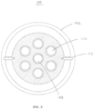
- FIG. 2 is an outlet end view of a cross-section of the flow restrictor nozzle of FIG. 1 .
- the nozzle body 102 of the flow restrictor nozzle 100 has a circular cross-section, although example embodiments are not limited thereto.
- the nozzle body 102 may alternatively have a polygonal cross-section.
- the nozzle body 102 defines a plurality of internal flow paths extending therethrough.
- the plurality of internal flow paths may be arranged in an evenly-spaced array (e.g., hexagonal lattice, triangular lattice) and centered within the nozzle body 102.
- the plurality of internal flow paths may be of the same cross-sectional shape and size.
- each of the plurality of internal flow paths may have a circular cross-sectional shape or other shape (e.g., elliptical cross-sectional shape).
- the plurality of internal flow paths may include a central flow path 108 and peripheral flow paths 110 surrounding the central flow path 108.
- the central flow path 108 may coincide with the central longitudinal axis of the nozzle body 102.
- Each of the peripheral flow paths 110 may be spaced equidistantly from the central flow path 108 as well as from adjacent peripheral flow paths 110. Although six peripheral flow paths 110 are shown, it should be understood that a different number may be implemented depending on the conditions.
- connection stubs 112 may be positioned between adjacent peripheral flow paths 110 while also being radially oriented so as point towards the center of the nozzle body 102 and, thus, the central flow path 108.
- the connection stubs 112 may be arranged at the 9 o'clock and 3 o'clock positions so as to be about 180 degrees apart.
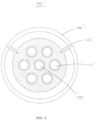
- FIG. 3 is an outlet end view of a cross-section of another flow restrictor nozzle according to an example embodiment.
- the flow restrictor nozzle 100' may be as described in connection with the flow restrictor nozzle 100 of FIG. 2 .
- the nozzle body 102', the central flow path 108', and the peripheral flow paths 110' of FIG. 3 may correspond to the nozzle body 102, the central flow path 108, and the peripheral flow paths 110 of FIG. 2 .
- the corresponding disclosures previously set forth will not be repeated in this section.
- each of the connection stubs 112' may be positioned between adjacent peripheral flow paths 110' while also being radially oriented so as point towards the center of the nozzle body 102' and, thus, the central flow path 108'.
- the connection stubs 112' may be arranged at the 10 o'clock and 2 o'clock positions so as to be 120 degrees apart.
- the connection stubs 112' may be regarded as being arranged at the 12 o'clock and 4 o'clock positions (or other positions depending on the rotation). In any event, the connection stubs 112' shown in FIG. 3 may be about 120 degrees apart regardless of the rotation.
- FIG. 4 is an outlet end view of a cross-section of another flow restrictor nozzle according to an example embodiment.
- the flow restrictor nozzle 100" may be as generally described in connection with the flow restrictor nozzle 100 of FIG. 2 .
- the corresponding disclosures previously set forth will not be repeated in this section.
- the differences shown in the flow restrictor nozzle 100" of FIG. 4 are discussed below.
- the plurality of internal flow paths may be shifted to one side of the nozzle body 102" (rather than being centered within the nozzle body 102").
- the plurality of internal flow paths may be of the same cross-sectional shape (e.g., circular cross-sectional shape) but of different sizes.
- the central flow path 108" may be larger than the peripheral flow paths 110".
- the central flow path 108" may also be off-center relative the central longitudinal axis of the nozzle body 102".
- the peripheral flow paths 110" may differ from each other in size.
- peripheral flow paths 110" may be of an intermediate size (relative to the central flow path 108"), while three of the peripheral flow paths 110" may be of a smaller size, although example embodiments are not limited thereto.
- one or more of the peripheral flow paths 110" may have different spacings from the central flow path 108" as well from each other.
- one central flow path 108" and seven peripheral flow paths 110" are shown, it should be understood that a different number may be implemented depending on the conditions.
- connection stubs 112" may be positioned between adjacent peripheral flow paths 110" while also being radially oriented so as point towards the central flow path 108".
- the connection stubs 112" may be arranged at the 11 o'clock and 1 o'clock positions so as to be 60 degrees apart.
- the connection stubs 112' may be regarded as being arranged at the 12 o'clock and 2 o'clock positions (or other positions depending on the rotation). In any event, as shown in FIG. 4 , the connection stubs 112' will be 60 degrees apart regardless of the rotation.
- FIG. 5 is an outlet end view of a cross-section of another flow restrictor nozzle according to an example embodiment.
- the flow restrictor nozzle 100′′′ may be as described in connection with the flow restrictor nozzle 100" of FIG. 4 .
- the nozzle body 102′′′, the central flow path 108′′′, and the connection stubs 112′′′ of FIG. 5 may correspond to the nozzle body 102", the central flow path 108", and the connection stubs 112" of FIG. 4 .
- the corresponding disclosures previously set forth will not be repeated in this section.
- the differences shown in the flow restrictor nozzle 100′′′ of FIG. 5 are discussed below.
- the peripheral flow paths 110′′′ may differ from each other in cross-sectional size and shape.
- two of the smaller-sized peripheral flow paths 110′′′ may have an elliptical cross-sectional shape.
- the nozzle body 102'" may be alternatively configured such that the central flow path 108′′′ is smaller in size than the peripheral flow paths 110′′′.
- the central flow path 108′′′ may have a different shape (e.g., elliptical cross-sectional shape) than as shown.
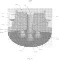
- FIG. 6 is an upper perspective view of a cross-section of a flow restrictor nozzle for a pressurized vessel of a nuclear reactor according to an example embodiment.
- the flow restrictor nozzle 200 comprises a nozzle body 202 including an inlet face 204 and an outlet face 206.
- the nozzle body 202 defines a plurality of internal flow paths extending from the inlet face 204 to the outlet face 206.
- the plurality of internal flow paths in FIG. 6 may correspond to the plurality of internal flow paths in FIG. 2 , although example embodiments are not limited thereto.
- the plurality of internal flow paths may extend in parallel through the nozzle body 202.
- Each of the plurality of internal flow paths includes a convergent section, a throat section, and a divergent section.
- the throat section of each of the plurality of internal flow paths is closer to the inlet face 204 than the outlet face 206 of the nozzle body 202.
- the plurality of internal flow paths include a central flow path 208 and peripheral flow paths 210 surrounding the central flow path 208.
- the central flow path 208 includes a convergent section 208a, a throat section 208b, and a divergent section 208c, while each of the peripheral flow paths 210 includes a convergent section 210a, a throat section 210b, and a divergent section 210c.
- the central flow path 208 may coincide with the central longitudinal axis of the nozzle body 202.
- Each of the peripheral flow paths 210 may be spaced equidistantly from the central flow path 208 as well as from adjacent peripheral flow paths 210, although example embodiments are not limited thereto.
- the inlet face 204 of the flow restrictor nozzle 200 may be a flanged section of the nozzle body 202, while the outlet face 206 of the flow restrictor nozzle 200 may be a tapered section of the nozzle body 202.
- the inlet face 204 may have a larger circumference and surface area than the outlet face 206.
- the flanged section of the nozzle body 202 may facilitate the attachment of the flow restrictor nozzle 200 to a pressurized vessel (e.g., steam generation vessel) of a nuclear reactor.
- a pressurized vessel e.g., steam generation vessel
- the inlet face 204 is shown as being concave, it should be understood that, in an alternative embodiment, the inlet face 204 may be convex depending on the target surface to which the flow restrictor nozzle 200 will be mounted.
- the nozzle body 202 may further include an instrument tap or a connection stub 212 protruding from the exterior of the nozzle body 202.
- an instrument tap or a connection stub 212 protruding from the exterior of the nozzle body 202.
- two oppositelyarranged connection stubs 212 may be provided.
- a pressure sensor may be connected to the connection stubs 212.
- the connection stub 212 may be in fluidic communication with the throat section 208b of the central flow path 208 via an opening 216.
- the opening 216 may be alternatively (or additionally) disposed in the throat section 210b of the peripheral flow path 210 so that the connection stub 212 is in fluidic communication with the throat section 210b via the opening 216.
- the nozzle body 202 may be a passive structure with no moving parts.
- the nozzle body 202 may be a monolithic structure.
- FIG. 7 is a side view of the cross-section of the flow restrictor nozzle of FIG. 6 .
- the convergent section 208a of the central flow path 208 may have a first area at the inlet face 204 of the nozzle body 202.
- the divergent section 208c of the central flow path 208 may have a second area at the outlet face 206 of the nozzle body 202.
- the throat section 208b of the central flow path 208 may have a third area at a narrowest part of the throat section 208b.
- the third area of the central flow path 208 may be less than the first area and the second area.
- the convergent section 210a of each of the peripheral flow path 210 may have a first area at the inlet face 204 of the nozzle body 202.
- the divergent section 210c of each of the peripheral flow paths 210 may have a second area at the outlet face 206 of the nozzle body 202.
- the throat section 210b of each of the peripheral flow paths 210 may have a third area at a narrowest part of the throat section 210b.
- the third area of each of the peripheral flow paths 210 may be less than the first area and the second area.
- the convergent section 208a of the central flow path 208 may have a first length.
- the divergent section 208c of the central flow path 208 may have a second length.
- the first length of the central flow path 208 may be less than the second length.
- the convergent section 210a of each of the peripheral flow paths 210 may have a first length.
- the divergent section 210c of each of the peripheral flow paths 210 may have a second length.
- the first length of each of the peripheral flow paths 210 may be less than the second length.
- the throat section 208b of the central flow path 208 is farther from the inlet face 204 of the nozzle body 202 than the throat section 210b of each of the peripheral flow paths 210.
- the throat section 208b of the central flow path 208 will be more downstream relative to the throat section 210b of each of the peripheral flow paths 210.
- FIG. 8 is an upper perspective view of another cross-section of the flow restrictor nozzle of FIG. 6 .
- the cross-section of the flow restrictor nozzle 200 in FIG. 8 is between adjacent peripheral flow paths 210 of the nozzle body 202.
- the nozzle body 202 may further define a pair of channels 214 extending from an exterior of the nozzle body 202 to the central flow path 208.
- Each of the connection stubs 212 may define an interior passage in fluidic communication with a corresponding one of the channels 214.
- the channels 214 may fluidically connect the connection stubs 212 to the throat section 208b of the central flow path 208.
- FIG. 8 is an upper perspective view of another cross-section of the flow restrictor nozzle of FIG. 6 .
- the cross-section of the flow restrictor nozzle 200 in FIG. 8 is between adjacent peripheral flow paths 210 of the nozzle body 202.
- the nozzle body 202 may further define a pair of channels 214 extending from an exterior of the nozzle body
- the channels 214 extend between adjacent peripheral flow paths 210 of the plurality of internal flow paths.
- the connection stubs 212 and the channels 214 may be diametrically and symmetrically arranged such that the opposing connection stubs 212 and associated channels 214 mirror each other.
- the channels 214 may also be provided so as to fluidically connect the connection stubs 212 to the throat section 210b of one or more of the peripheral flow paths 210.
- FIG. 9 is a side view of the cross-section of the flow restrictor nozzle of FIG. 8 .
- the channels 214 may extend inward at an angle toward the inlet face 204 of the nozzle body 202.
- the channels 214 extend to the throat section 208b of the central flow path 208.
- the channels 214 may be regarded as converging at the throat section 208b of the central flow path 208, although different openings 216 ( FIG. 6 ) are associated with each channel 214.
- the connection stubs 212 may be arranged at approximately a midway point between the inlet face 204 and the outlet face 206 of the nozzle body 202, although example embodiments are not limited thereto.
- FIG. 10 is a lower perspective view of the cross-section of the flow restrictor nozzle of FIG. 8 .
- the convergent section 208a of the central flow path 208 and the convergent sections 210a of the peripheral flow paths 210 may be directly adjacent to one another so as to have shared boundaries at the inlet face 204 of the nozzle body 202.
- the boundary of a convergent section 210a of one of the peripheral flow paths 210 at the inlet face 204 of the nozzle body 202 may also form a part of the boundaries of two of the convergent sections 210a of the peripheral flow paths 210 adjacent to it.
- the boundaries of the convergent sections 210a of the peripheral flow paths 210 may form the boundary of the convergent section 208a of the central flow path 208 at the inlet face 204 of the nozzle body 202.
- a method of restricting a flow from a pressurized vessel of a nuclear reactor may comprise securing a flow restrictor nozzle 200 to the pressurized vessel.
- the flow restrictor nozzle 200 has a nozzle body 202 including an inlet face 204 and an outlet face 206.
- the nozzle body 202 defines a plurality of internal flow paths extending from the inlet face 204 to the outlet face 206.
- Each of the plurality of internal flow paths includes a convergent section, a throat section, and a divergent section.
- the method comprises directing the flow from the pressurized vessel through the plurality of internal flow paths of the flow restrictor nozzle 200.
- the securing may include welding the flow restrictor nozzle 200 to an exterior of the pressurized vessel.
- the flow restrictor nozzle 200 may be a monolithic structure.
- the securing may include attaching a first section of the flow restrictor nozzle to the pressurized vessel and attaching a second section of the flow restrictor nozzle to the first section.
- the directing of the flow may result in a choked flow exiting the flow restrictor nozzle 200.
- the directing of the flow may also result in a stabilized flow exiting at equal velocity from the flow restrictor nozzle 200.
- a method of manufacturing a flow restrictor nozzle 200 for a pressurized vessel of a nuclear reactor may comprise fabricating a nozzle body 202 including an inlet face 204 and an outlet face 206.
- the nozzle body 202 defines a plurality of internal flow paths extending from the inlet face 204 to the outlet face 206.
- Each of the plurality of internal flow paths includes a convergent section, a throat section, and a divergent section.
- the method may additionally comprise independently shaping, sizing, and positioning the convergent section of each of the plurality of internal flow paths on the inlet face 204 based on predicted pressure variances of the pressurized vessel.
- the method may further comprise independently spacing the throat section of each of the plurality of internal flow paths relative to the inlet face 204 to mitigate acoustic wave reinforcement.
- the flow restrictor nozzle disclosed herein and the associated design, use, and manufacture thereof are discussed in further detail below in accordance with example embodiments of the present application. Described herein is a flow restrictor nozzle for use in steam generation vessels with features of compactness using multiple parallel paths, nozzle axis angling and inflow and outflow port shaping to control pressure variations, flow distribution, flow swirl, and acoustic pressure wave transmission.
- the flow restrictor nozzle is designed to be replaceable/renewable after installation.
- the flow restrictor nozzle has no moving parts.
- the flow restrictor nozzle may be applied to new or existing vessels.
- the flow restrictor nozzle may be utilized in connection with steam service vessel flow restriction, in saturated or superheated state. However, it should be understood that the flow restrictor nozzle may also be applied in other vapor, gas, and/or liquid (e.g., water) applications with vessel flow restriction nozzle requirements.
- Fluid mechanic principles are applied to address the problems affecting current nozzles.
- multiple parallel flow paths are each formed using a combination of flow nozzle intake and Venturi nozzle discharge flow principles.
- Inlet pressure fields and flows are generally non-uniform and unstable and often have entrained eddies and swirls.
- the number of individual flow path ports, the port shapes, the angle of entry, port locations, accessory features, and individual throat sizes in a multiple parallel flow path restrictor nozzle can be correspondingly varied to mitigate the adverse effects of these inlet conditions.
- Inlet port surfaces can be smooth and uniform or may have convolutions or fluting.
- the shape can be circular, oval, elliptical, or an asymmetric version of oval or elliptical shapes.
- the throat area can be uniform for all ports of a nozzle or can vary to take advantage of non-uniform pressure field prediction at the inlet so that the portion of the nozzle inlet face with higher pressure has a larger throat flow area while the inlet face portion with lower pressure has a smaller throat flow area.
- the total flow area is approximately equivalent to the flow area of a single-path flow restrictor nozzle.
- the throat location within the nozzle can be at a uniform distance from the inlet surface or can be varied in accordance with acoustic analysis to prevent or reduce acoustic wave reinforcement at the inlet or outlet of the multiple-path flow restrictor nozzle.
- Discharge nozzles are relatively shallow angle, following the engineering rules for Venturi expansions, to obtain maximum pressure recovery with minimum total pressure loss from the throat to the nozzle outlet face.
- Discharge nozzles can be in parallel to a single straight pipeline axis that is orthogonal to the nozzle outlet end.
- the outlet flow paths from the throat section can be angled by several degrees to optimize the piping connection interface at the nozzle outlet end.
- Accessory features may include inlet or outlet anti-swirl (flow straightening) blades, varying thickness of erosion resistant weld overlay material, and pressure sensor taps.
- the entire nozzle may be formed as a single piece.
- the nozzle may be composed of two pieces, with the two-piece form permitting nozzle removal/replacement during the equipment service life.
- the nozzle form can be manufactured according to at least three approaches.
- the single piece multiple parallel flow path flow restrictor nozzle is a permanent form that is welded into a vessel during original shop fabrication.
- the first piece of a two-piece nozzle form is welded into a vessel and provides a socket or chamber into which a second multiport restrictor element piece is mechanically inserted and secured prior to unit service.
- the first piece is a mechanical locking mechanism that is inserted into place inside an existing nozzle bore using the principle of interference fit by material cryogenic shrink, with an external mechanical pattern that seals and locks the piece permanently as it re-expands by thermal equalization. With the locking mechanism in place, a second multi-path restrictor element piece is mechanically inserted and secured prior to unit service.
- the throat diameter of each flow path is decreased so that the total flow restrictor function is satisfied by the sum effect of the parallel flow path restrictions, which reduces the overall recovery length of the Venturi discharges so that the overall nozzle is much shorter than the equivalent single flow path nozzle.
- the multiple-path flow restrictor nozzle's total diameter remains very close to that of the equivalent single-path nozzle so that vessel fabrication impact is negligible.
- the nozzle length is a function of the Venturi discharge expansion length which is directly proportional to throat orifice diameter.
- a shortened flow recovery length from the smaller throat orifices of individual paths to the nozzle discharge face makes the nozzle compact enough to be fully installed into the vessel during shop fabrication and requires no expensive, time-consuming, and space-consuming field fitting, welding, and heat treatment of nozzle extensions to complete the vessel nozzle fabrication after field placement
- the mass flow per unit area of the flow paths can be equalized by more closely matching the available flow area to the inlet pressure distribution at the nozzle inlet face.
- the flows then pass through the parallel flow paths at equal velocity. This contributes to minimizing the potential for generating adverse flow phenomena in any individual flow path due to relative flow "starving" compared to other ports of the nozzle, and to eddies at the nozzle exit or downstream flow area displacement caused by recirculating-flow stall conditions due to recombination of individual path flows at different velocities.
- Acoustic waves generated in the piping downstream from the nozzle can cause damage to vessel internal structures by high-cycle fatigue.
- Low frequency acoustic waves carry the most energy and are the most capable of causing metal fatigue failure of vessel internal structures.
- the acoustic pressure waves are partially attenuated by the multiple parallel flow path flow restrictor nozzle by reflection of some of the wave energy.
- the remainder of the wave energy is subject to frequency conversion and energy division by individual higher frequency wave packets that are generated in each of the smaller diameter parallel flow paths of the nozzle.
- Acoustic detuning of the design avoids having these transmitted higher frequency wave packets recombine to reinforce each other. Therefore, the energy impulses that reach the vessel internal structures are further from internal structure resonance frequencies and are of lower energy. This mitigates the potential for internal structure failure from piping system acoustically induced high-cycle fatigue.
- Accessory features of the nozzle design are used to further enhance performance, improve mass-energy transmission efficiency, and assist in flow monitoring.
- fluted inlets may be used to enhance flow entry in the direction of the flow axis and disrupt parasitic drag phenomena caused by swirl.
- the apexes may be sharply peaked to trip cross-flows, or are joined to form flow straightening blades (foils, vanes), such as a bisecting blade, tri-blade or quad-blade pattern.
- flow-straightening blades can be included at the individual Venturi expansion outlets to limit swirl development due to transition eddies formed before the flow reaches full pipe diameter.
- the anti-swirl blades may stabilize flow streams by canceling the cross-flow streams that are a source of drag and downstream eddies.
- the location of the nozzle discharge face connection to piping can be adjusted to improve the system piping interface, reducing the required pipe bends that tend to re-introduce swirl in the downstream flow.
- weld metal overlay addresses areas with higher erosion potential and allows for flow path shaping during fabrication by selective machining and smoothing of the surface.
- Pressure sensing ports can measure upstream (inlet face) and throat pressures so that the mass flow rate through the nozzle can be determined using a differential pressure to flow rate equivalency.
- the nozzle design herein substantially reduces the pressure losses caused by flow swirl that has been analytically demonstrated, and is evidenced by an observable polishing effect on steam dryer outer bank surfaces directly opposite the steam nozzles.
- Improved steam flow delivery increases the potential megawatt-electric output of the unit without adding additional core energy.
- Elimination of field vessel fabrication steps of the current restrictor nozzle design saves significant construction cost.
- the improved interface with the main steam piping also contributes to improved steam delivery.
- the compact design of the multiple-path flow restrictor nozzle allows the complete nozzle to be installed into the pressure vessel without interference with other structures surrounding the vessel or in the vicinity of the steam nozzles.
- the acoustic wave attenuation reduces the cyclic loading of the steam dryer assembly due to downstream acoustic generators (e.g., relief valve branch piping). This mitigates the potential for dryer failures. Furthermore, the smaller flow path orifices of the multiple-path flow restrictor nozzle design would effectively block all but the smaller pieces of debris from being discharged into the steam lines. This debris screening is especially effective if the nozzle design installed in any particular plant's vessel includes inlet, outlet, or inlet and outlet flow straightening blades.
- the partial blockage of acoustic waves includes impulse or shock waves due to sudden valve closures in the downstream piping system, mitigating the transient loads experienced by the vessel internals. This consequently facilitates faster closure times for closing the downstream piping to reduce mass discharge early in a steam system transient event.
- Designing the restrictor nozzle for initial thick-overlay cladding provides a built-in means to adapt the nozzle for a power/flow increase in later service by permitting a portion of the clad to be machined away for a re-profiling of the pathways and recertification of the restrictor nozzle's capacity rating.
- the two-piece design described herein simplifies the original component parts shop fabrication. This concept also permits routine inspection of the restrictor element outside the vessel. Away-from-vessel maintenance facilitates and simplifies refurbishment or replacement of the restrictor element because no welding is involved and all work can be performed in a controlled shop environment. Performing maintenance work remotely from the vessel considerably reduces the material risk of damaging the vessel or losing foreign material in the vessel, and reduces the risk to maintenance personnel performing the work. It also allows use of standard precision shop tools and more accurate and complex methods than possible with in-situ inspection or repair. The ability to swap out restrictor elements permits rapid refitting of a vessel for a change in the design mass flow rate because a new insert piece can be fabricated and certified in advance of the change.
- the material selection options for fabricating the restrictor element insert can make use of a broader selection of available corrosion or erosion resistant materials and alloys, which are also thermally compatible with the vessel and main nozzle chamber base material.
- the restrictor nozzle By designing a multiple-path flow steam flow restrictor element with integral pressure-sensing ports for the inlet face static pressure and the dominant path (e.g., central port) Venturi throat pressure, the restrictor nozzle can be calibrated and capacity certified in a test stand. This can be performed external from the plant.
- the differential-pressure instrumentation connections for the nozzle are simplified and provide assurance of accurate in-service measurement of the nozzle performance.
Landscapes
- Physics & Mathematics (AREA)
- Engineering & Computer Science (AREA)
- High Energy & Nuclear Physics (AREA)
- General Engineering & Computer Science (AREA)
- Plasma & Fusion (AREA)
- Thermal Sciences (AREA)
- Mechanical Engineering (AREA)
- Nozzles (AREA)
- Jet Pumps And Other Pumps (AREA)
- Monitoring And Testing Of Nuclear Reactors (AREA)
Applications Claiming Priority (2)
| Application Number | Priority Date | Filing Date | Title |
|---|---|---|---|
| US15/845,277 US11232874B2 (en) | 2017-12-18 | 2017-12-18 | Multiple-path flow restrictor nozzle |
| PCT/US2018/062632 WO2019168572A2 (en) | 2017-12-18 | 2018-11-27 | Multiple-path flow restrictor nozzle |
Publications (3)
| Publication Number | Publication Date |
|---|---|
| EP3729465A2 EP3729465A2 (en) | 2020-10-28 |
| EP3729465A4 EP3729465A4 (en) | 2021-09-08 |
| EP3729465B1 true EP3729465B1 (en) | 2023-06-21 |
Family
ID=66816211
Family Applications (1)
| Application Number | Title | Priority Date | Filing Date |
|---|---|---|---|
| EP18907542.7A Active EP3729465B1 (en) | 2017-12-18 | 2018-11-27 | Multiple-path flow restrictor nozzle |
Country Status (6)
| Country | Link |
|---|---|
| US (1) | US11232874B2 (enExample) |
| EP (1) | EP3729465B1 (enExample) |
| JP (1) | JP7250020B2 (enExample) |
| FI (1) | FI3729465T3 (enExample) |
| PL (1) | PL3729465T3 (enExample) |
| WO (1) | WO2019168572A2 (enExample) |
Families Citing this family (2)
| Publication number | Priority date | Publication date | Assignee | Title |
|---|---|---|---|---|
| US11232874B2 (en) * | 2017-12-18 | 2022-01-25 | Ge-Hitachi Nuclear Energy Americas Llc | Multiple-path flow restrictor nozzle |
| US11293298B2 (en) * | 2019-12-05 | 2022-04-05 | Raytheon Technologies Corporation | Heat transfer coefficients in a compressor case for improved tip clearance control system |
Family Cites Families (44)
| Publication number | Priority date | Publication date | Assignee | Title |
|---|---|---|---|---|
| US1626047A (en) * | 1925-12-11 | 1927-04-26 | Majestic Mfg Company | Gas stove |
| GB1264241A (enExample) * | 1969-01-23 | 1972-02-16 | ||
| US3622081A (en) * | 1969-06-20 | 1971-11-23 | Nestle Sa | Nozzle |
| US3945574A (en) | 1972-07-24 | 1976-03-23 | Polnauer Frederick F | Dual orifice spray nozzle using two swirl chambers |
| US3878991A (en) | 1974-02-14 | 1975-04-22 | Gen Foods Corp | Steam nozzle |
| US4071403A (en) * | 1974-08-01 | 1978-01-31 | Westinghouse Electric Corporation | Method and apparatus for protecting the core of a nuclear reactor |
| US4361285A (en) | 1980-06-03 | 1982-11-30 | Fluid Kinetics, Inc. | Mixing nozzle |
| US4652234A (en) | 1984-03-01 | 1987-03-24 | Voorheis Industries, Inc. | Constant pressure-variable orifice burner nozzle assembly |
| FR2602309B1 (fr) * | 1986-07-30 | 1988-11-10 | Soudure Autogene Francaise | Buse de coupe siderurgique a double couronne de chauffe |
| JP2811682B2 (ja) * | 1988-09-22 | 1998-10-15 | 石川島播磨重工業株式会社 | 原子炉圧力容器の主蒸気ノズル |
| JPH087274B2 (ja) * | 1990-08-22 | 1996-01-29 | 株式会社日立製作所 | 原子炉圧力容器直付型流量計測ノズル |
| US5090619A (en) * | 1990-08-29 | 1992-02-25 | Pinnacle Innovations | Snow gun having optimized mixing of compressed air and water flows |
| JP2509753B2 (ja) * | 1990-11-15 | 1996-06-26 | 株式会社東芝 | 原子炉主蒸気流量計 |
| US5103800A (en) | 1991-05-13 | 1992-04-14 | Cleveland Range, Inc. | Nozzle for steam cooking device |
| US5385121A (en) | 1993-01-19 | 1995-01-31 | Keystone International Holdings Corp. | Steam desuperheater |
| EP0681301A1 (en) | 1994-05-04 | 1995-11-08 | General Electric Company | Feedwater nozzle and method of repair |
| JPH087274A (ja) | 1994-06-16 | 1996-01-12 | Sony Magnescale Inc | 転写装置 |
| US5613535A (en) * | 1995-06-05 | 1997-03-25 | Shell Oil Company | Fuel dispenser shutoff switch |
| SE512027C2 (sv) * | 1998-05-15 | 2000-01-17 | Silvent Ab | Ljuddämpat blåsmunstycke |
| US6585063B2 (en) * | 2000-12-14 | 2003-07-01 | Smith International, Inc. | Multi-stage diffuser nozzle |
| DE60122709D1 (de) * | 2001-08-20 | 2006-10-12 | Schlumberger Services Petrol | Mehrphasen-Durchflussmesser mit veränderlicher Venturi-Düse |
| US6969489B2 (en) * | 2001-08-24 | 2005-11-29 | Cytoplex Biosciences | Micro array for high throughout screening |
| US7270713B2 (en) * | 2003-01-07 | 2007-09-18 | Applied Materials, Inc. | Tunable gas distribution plate assembly |
| KR20050007941A (ko) * | 2003-07-12 | 2005-01-21 | 두산중공업 주식회사 | 증기 발생기의 다중 확산기 노즐 설계 방법 |
| FR2866410B1 (fr) * | 2004-02-17 | 2006-05-19 | Gaz De France | Conditionneur d'ecoulement pour canalisation de transport de fluide |
| JP2006300535A (ja) | 2005-04-15 | 2006-11-02 | Nuclear Fuel Ind Ltd | 高温ガス炉用被覆燃料粒子製造装置のガス導入ノズル |
| US7945938B2 (en) | 2005-05-11 | 2011-05-17 | Canon Kabushiki Kaisha | Network camera system and control method therefore |
| SE534983C2 (sv) | 2006-06-21 | 2012-03-06 | Clyde Bergemann Inc | Munstycke för svartlut med variabel mynning |
| US8312931B2 (en) * | 2007-10-12 | 2012-11-20 | Baker Hughes Incorporated | Flow restriction device |
| JP5470656B2 (ja) | 2010-03-16 | 2014-04-16 | 株式会社マスダック | 過熱水蒸気発生ノズル |
| EP2555752B1 (en) * | 2010-04-09 | 2019-06-26 | Pacira Pharmaceuticals, Inc. | Method for formulating multivesicular liposomes |
| AU2012253569B2 (en) * | 2011-05-09 | 2018-02-15 | Impel Pharmaceuticals Inc. | Nozzles for nasal drug delivery |
| US9091429B2 (en) | 2011-08-03 | 2015-07-28 | Westinghouse Electric Company Llc | Nuclear steam generator steam nozzle flow restrictor |
| WO2013025421A1 (en) * | 2011-08-14 | 2013-02-21 | Watermiser, Llc | Elliptical chambered flow restrictor |
| DE102012000536B3 (de) | 2012-01-16 | 2013-05-16 | Areva Np Gmbh | Passiver Rückflussbegrenzer für ein Strömungsmedium |
| US10182696B2 (en) * | 2012-09-27 | 2019-01-22 | Dehn's Innovations, Llc | Steam nozzle system and method |
| CN103187113B (zh) | 2013-01-18 | 2017-03-01 | 上海核工程研究设计院 | 一种核电站蒸汽发生器蒸汽限流装置 |
| US9463342B2 (en) * | 2014-03-17 | 2016-10-11 | International Fog, Inc. | Fog-cloud generated nozzle |
| KR101817212B1 (ko) * | 2016-04-29 | 2018-02-21 | 세메스 주식회사 | 처리액 분사 유닛 및 기판 처리 장치 |
| US9987508B2 (en) * | 2016-08-31 | 2018-06-05 | Emerson Process Management Regulator Technologies Tulsa, Llc | Hybrid composite flame cell |
| US20180056100A1 (en) * | 2016-08-31 | 2018-03-01 | Emerson Process Management Regulator Technologies Tulsa, Llc | Method for Manufacturing a Flame Arrestor |
| JP6876447B2 (ja) * | 2017-01-24 | 2021-05-26 | 日立Geニュークリア・エナジー株式会社 | 原子力発電プラント |
| US10811232B2 (en) * | 2017-08-08 | 2020-10-20 | Applied Materials, Inc. | Multi-plate faceplate for a processing chamber |
| US11232874B2 (en) * | 2017-12-18 | 2022-01-25 | Ge-Hitachi Nuclear Energy Americas Llc | Multiple-path flow restrictor nozzle |
-
2017
- 2017-12-18 US US15/845,277 patent/US11232874B2/en active Active
-
2018
- 2018-11-27 PL PL18907542.7T patent/PL3729465T3/pl unknown
- 2018-11-27 FI FIEP18907542.7T patent/FI3729465T3/fi active
- 2018-11-27 EP EP18907542.7A patent/EP3729465B1/en active Active
- 2018-11-27 WO PCT/US2018/062632 patent/WO2019168572A2/en not_active Ceased
- 2018-11-27 JP JP2020532910A patent/JP7250020B2/ja active Active
Also Published As
| Publication number | Publication date |
|---|---|
| JP7250020B2 (ja) | 2023-03-31 |
| US20190189297A1 (en) | 2019-06-20 |
| WO2019168572A2 (en) | 2019-09-06 |
| FI3729465T3 (fi) | 2023-07-19 |
| WO2019168572A3 (en) | 2019-11-07 |
| EP3729465A4 (en) | 2021-09-08 |
| EP3729465A2 (en) | 2020-10-28 |
| JP2021506572A (ja) | 2021-02-22 |
| PL3729465T3 (pl) | 2023-08-21 |
| US11232874B2 (en) | 2022-01-25 |
Similar Documents
| Publication | Publication Date | Title |
|---|---|---|
| EP1914393B1 (en) | Steam valve and steam turbine plant | |
| US20120160346A1 (en) | Nozzle check valve | |
| EP1574764B1 (en) | Valve | |
| EP2428728A1 (en) | Steam generator | |
| US20120240580A1 (en) | Steam valve device and steam turbine plant | |
| EP3729465B1 (en) | Multiple-path flow restrictor nozzle | |
| JP3968181B2 (ja) | 蒸気循環装置における組合せ弁構造 | |
| JPS59122803A (ja) | 蒸気タ−ビンの再熱装置 | |
| US20150000748A1 (en) | Check Valve Apparatus And Methods | |
| EP2796669B1 (en) | Steam valve apparatus | |
| US4230410A (en) | Mixing device for fluids of different and varying temperatures | |
| EP3296514A1 (en) | Fluidically controlled steam turbine inlet scroll | |
| WO2019058394A1 (en) | JET IMPACT COOLING SYSTEM WITH ENHANCED SHOWERHEAD ARRANGEMENT FOR GAS TURBINE BLADES | |
| CN118934112A (zh) | 一种汽轮机旁路扩散器结构 | |
| JP2018087502A (ja) | 蒸気タービン装置の運転方法及び蒸気タービン装置 | |
| US11852272B2 (en) | Check valve assembly | |
| CN214500222U (zh) | 一种具有防冲蚀作用的控制阀 | |
| CN107689257A (zh) | 一种用于解决核电厂蒸汽管道冲蚀的支管连接系统 | |
| EP4493856B1 (en) | Flow conditioning device for steam generator | |
| CN104989529B (zh) | 控制涡轮叶栅顶部端区流动的闭环式引气射流系统 | |
| KR101389054B1 (ko) | 일체형 케이싱 시스템을 구비한 수력기계 | |
| US20250243796A1 (en) | Controlling noise on safety valves | |
| JP2010168984A (ja) | ジェットポンプ及び原子炉 | |
| CN121025286A (zh) | 反射式防堵单向节流装置 | |
| CN120906688A (zh) | 一种降低重型燃气轮机空气系统阻力损失的长行程减涡装置 |
Legal Events
| Date | Code | Title | Description |
|---|---|---|---|
| STAA | Information on the status of an ep patent application or granted ep patent |
Free format text: STATUS: THE INTERNATIONAL PUBLICATION HAS BEEN MADE |
|
| PUAI | Public reference made under article 153(3) epc to a published international application that has entered the european phase |
Free format text: ORIGINAL CODE: 0009012 |
|
| STAA | Information on the status of an ep patent application or granted ep patent |
Free format text: STATUS: REQUEST FOR EXAMINATION WAS MADE |
|
| 17P | Request for examination filed |
Effective date: 20200720 |
|
| AK | Designated contracting states |
Kind code of ref document: A2 Designated state(s): AL AT BE BG CH CY CZ DE DK EE ES FI FR GB GR HR HU IE IS IT LI LT LU LV MC MK MT NL NO PL PT RO RS SE SI SK SM TR |
|
| AX | Request for extension of the european patent |
Extension state: BA ME |
|
| DAV | Request for validation of the european patent (deleted) | ||
| DAX | Request for extension of the european patent (deleted) | ||
| A4 | Supplementary search report drawn up and despatched |
Effective date: 20210806 |
|
| RIC1 | Information provided on ipc code assigned before grant |
Ipc: B05B 1/14 20060101ALN20210802BHEP Ipc: B05B 1/00 20060101ALI20210802BHEP Ipc: F22B 37/26 20060101ALI20210802BHEP Ipc: G21C 15/16 20060101ALI20210802BHEP Ipc: G21C 13/032 20060101ALI20210802BHEP Ipc: G21C 13/02 20060101AFI20210802BHEP |
|
| RIC1 | Information provided on ipc code assigned before grant |
Ipc: B05B 1/14 20060101ALN20221125BHEP Ipc: B05B 1/00 20060101ALI20221125BHEP Ipc: F22B 37/26 20060101ALI20221125BHEP Ipc: G21C 15/16 20060101ALI20221125BHEP Ipc: G21C 13/032 20060101ALI20221125BHEP Ipc: G21C 13/02 20060101AFI20221125BHEP |
|
| GRAP | Despatch of communication of intention to grant a patent |
Free format text: ORIGINAL CODE: EPIDOSNIGR1 |
|
| STAA | Information on the status of an ep patent application or granted ep patent |
Free format text: STATUS: GRANT OF PATENT IS INTENDED |
|
| RIC1 | Information provided on ipc code assigned before grant |
Ipc: B05B 1/14 20060101ALN20221220BHEP Ipc: B05B 1/00 20060101ALI20221220BHEP Ipc: F22B 37/26 20060101ALI20221220BHEP Ipc: G21C 15/16 20060101ALI20221220BHEP Ipc: G21C 13/032 20060101ALI20221220BHEP Ipc: G21C 13/02 20060101AFI20221220BHEP |
|
| INTG | Intention to grant announced |
Effective date: 20230123 |
|
| GRAS | Grant fee paid |
Free format text: ORIGINAL CODE: EPIDOSNIGR3 |
|
| GRAA | (expected) grant |
Free format text: ORIGINAL CODE: 0009210 |
|
| STAA | Information on the status of an ep patent application or granted ep patent |
Free format text: STATUS: THE PATENT HAS BEEN GRANTED |
|
| AK | Designated contracting states |
Kind code of ref document: B1 Designated state(s): AL AT BE BG CH CY CZ DE DK EE ES FI FR GB GR HR HU IE IS IT LI LT LU LV MC MK MT NL NO PL PT RO RS SE SI SK SM TR |
|
| REG | Reference to a national code |
Ref country code: CH Ref legal event code: EP |
|
| REG | Reference to a national code |
Ref country code: DE Ref legal event code: R096 Ref document number: 602018052271 Country of ref document: DE |
|
| REG | Reference to a national code |
Ref country code: AT Ref legal event code: REF Ref document number: 1581499 Country of ref document: AT Kind code of ref document: T Effective date: 20230715 |
|
| REG | Reference to a national code |
Ref country code: IE Ref legal event code: FG4D Ref country code: FI Ref legal event code: FGE |
|
| REG | Reference to a national code |
Ref country code: SE Ref legal event code: TRGR |
|
| REG | Reference to a national code |
Ref country code: LT Ref legal event code: MG9D |
|
| REG | Reference to a national code |
Ref country code: NL Ref legal event code: MP Effective date: 20230621 |
|
| PG25 | Lapsed in a contracting state [announced via postgrant information from national office to epo] |
Ref country code: NO Free format text: LAPSE BECAUSE OF FAILURE TO SUBMIT A TRANSLATION OF THE DESCRIPTION OR TO PAY THE FEE WITHIN THE PRESCRIBED TIME-LIMIT Effective date: 20230921 |
|
| REG | Reference to a national code |
Ref country code: AT Ref legal event code: MK05 Ref document number: 1581499 Country of ref document: AT Kind code of ref document: T Effective date: 20230621 |
|
| PG25 | Lapsed in a contracting state [announced via postgrant information from national office to epo] |
Ref country code: RS Free format text: LAPSE BECAUSE OF FAILURE TO SUBMIT A TRANSLATION OF THE DESCRIPTION OR TO PAY THE FEE WITHIN THE PRESCRIBED TIME-LIMIT Effective date: 20230621 Ref country code: NL Free format text: LAPSE BECAUSE OF FAILURE TO SUBMIT A TRANSLATION OF THE DESCRIPTION OR TO PAY THE FEE WITHIN THE PRESCRIBED TIME-LIMIT Effective date: 20230621 Ref country code: LV Free format text: LAPSE BECAUSE OF FAILURE TO SUBMIT A TRANSLATION OF THE DESCRIPTION OR TO PAY THE FEE WITHIN THE PRESCRIBED TIME-LIMIT Effective date: 20230621 Ref country code: LT Free format text: LAPSE BECAUSE OF FAILURE TO SUBMIT A TRANSLATION OF THE DESCRIPTION OR TO PAY THE FEE WITHIN THE PRESCRIBED TIME-LIMIT Effective date: 20230621 Ref country code: HR Free format text: LAPSE BECAUSE OF FAILURE TO SUBMIT A TRANSLATION OF THE DESCRIPTION OR TO PAY THE FEE WITHIN THE PRESCRIBED TIME-LIMIT Effective date: 20230621 Ref country code: GR Free format text: LAPSE BECAUSE OF FAILURE TO SUBMIT A TRANSLATION OF THE DESCRIPTION OR TO PAY THE FEE WITHIN THE PRESCRIBED TIME-LIMIT Effective date: 20230922 |
|
| PG25 | Lapsed in a contracting state [announced via postgrant information from national office to epo] |
Ref country code: SK Free format text: LAPSE BECAUSE OF FAILURE TO SUBMIT A TRANSLATION OF THE DESCRIPTION OR TO PAY THE FEE WITHIN THE PRESCRIBED TIME-LIMIT Effective date: 20230621 |
|
| PG25 | Lapsed in a contracting state [announced via postgrant information from national office to epo] |
Ref country code: ES Free format text: LAPSE BECAUSE OF FAILURE TO SUBMIT A TRANSLATION OF THE DESCRIPTION OR TO PAY THE FEE WITHIN THE PRESCRIBED TIME-LIMIT Effective date: 20230621 |
|
| PG25 | Lapsed in a contracting state [announced via postgrant information from national office to epo] |
Ref country code: IS Free format text: LAPSE BECAUSE OF FAILURE TO SUBMIT A TRANSLATION OF THE DESCRIPTION OR TO PAY THE FEE WITHIN THE PRESCRIBED TIME-LIMIT Effective date: 20231021 |
|
| PG25 | Lapsed in a contracting state [announced via postgrant information from national office to epo] |
Ref country code: SM Free format text: LAPSE BECAUSE OF FAILURE TO SUBMIT A TRANSLATION OF THE DESCRIPTION OR TO PAY THE FEE WITHIN THE PRESCRIBED TIME-LIMIT Effective date: 20230621 Ref country code: SK Free format text: LAPSE BECAUSE OF FAILURE TO SUBMIT A TRANSLATION OF THE DESCRIPTION OR TO PAY THE FEE WITHIN THE PRESCRIBED TIME-LIMIT Effective date: 20230621 Ref country code: RO Free format text: LAPSE BECAUSE OF FAILURE TO SUBMIT A TRANSLATION OF THE DESCRIPTION OR TO PAY THE FEE WITHIN THE PRESCRIBED TIME-LIMIT Effective date: 20230621 Ref country code: PT Free format text: LAPSE BECAUSE OF FAILURE TO SUBMIT A TRANSLATION OF THE DESCRIPTION OR TO PAY THE FEE WITHIN THE PRESCRIBED TIME-LIMIT Effective date: 20231023 Ref country code: IS Free format text: LAPSE BECAUSE OF FAILURE TO SUBMIT A TRANSLATION OF THE DESCRIPTION OR TO PAY THE FEE WITHIN THE PRESCRIBED TIME-LIMIT Effective date: 20231021 Ref country code: ES Free format text: LAPSE BECAUSE OF FAILURE TO SUBMIT A TRANSLATION OF THE DESCRIPTION OR TO PAY THE FEE WITHIN THE PRESCRIBED TIME-LIMIT Effective date: 20230621 Ref country code: EE Free format text: LAPSE BECAUSE OF FAILURE TO SUBMIT A TRANSLATION OF THE DESCRIPTION OR TO PAY THE FEE WITHIN THE PRESCRIBED TIME-LIMIT Effective date: 20230621 Ref country code: CZ Free format text: LAPSE BECAUSE OF FAILURE TO SUBMIT A TRANSLATION OF THE DESCRIPTION OR TO PAY THE FEE WITHIN THE PRESCRIBED TIME-LIMIT Effective date: 20230621 Ref country code: AT Free format text: LAPSE BECAUSE OF FAILURE TO SUBMIT A TRANSLATION OF THE DESCRIPTION OR TO PAY THE FEE WITHIN THE PRESCRIBED TIME-LIMIT Effective date: 20230621 |
|
| REG | Reference to a national code |
Ref country code: DE Ref legal event code: R097 Ref document number: 602018052271 Country of ref document: DE |
|
| PLBE | No opposition filed within time limit |
Free format text: ORIGINAL CODE: 0009261 |
|
| STAA | Information on the status of an ep patent application or granted ep patent |
Free format text: STATUS: NO OPPOSITION FILED WITHIN TIME LIMIT |
|
| PG25 | Lapsed in a contracting state [announced via postgrant information from national office to epo] |
Ref country code: DK Free format text: LAPSE BECAUSE OF FAILURE TO SUBMIT A TRANSLATION OF THE DESCRIPTION OR TO PAY THE FEE WITHIN THE PRESCRIBED TIME-LIMIT Effective date: 20230621 |
|
| PG25 | Lapsed in a contracting state [announced via postgrant information from national office to epo] |
Ref country code: SI Free format text: LAPSE BECAUSE OF FAILURE TO SUBMIT A TRANSLATION OF THE DESCRIPTION OR TO PAY THE FEE WITHIN THE PRESCRIBED TIME-LIMIT Effective date: 20230621 |
|
| 26N | No opposition filed |
Effective date: 20240322 |
|
| PG25 | Lapsed in a contracting state [announced via postgrant information from national office to epo] |
Ref country code: SI Free format text: LAPSE BECAUSE OF FAILURE TO SUBMIT A TRANSLATION OF THE DESCRIPTION OR TO PAY THE FEE WITHIN THE PRESCRIBED TIME-LIMIT Effective date: 20230621 Ref country code: IT Free format text: LAPSE BECAUSE OF FAILURE TO SUBMIT A TRANSLATION OF THE DESCRIPTION OR TO PAY THE FEE WITHIN THE PRESCRIBED TIME-LIMIT Effective date: 20230621 |
|
| REG | Reference to a national code |
Ref country code: DE Ref legal event code: R119 Ref document number: 602018052271 Country of ref document: DE |
|
| REG | Reference to a national code |
Ref country code: CH Ref legal event code: PL |
|
| PG25 | Lapsed in a contracting state [announced via postgrant information from national office to epo] |
Ref country code: MC Free format text: LAPSE BECAUSE OF FAILURE TO SUBMIT A TRANSLATION OF THE DESCRIPTION OR TO PAY THE FEE WITHIN THE PRESCRIBED TIME-LIMIT Effective date: 20230621 |
|
| PG25 | Lapsed in a contracting state [announced via postgrant information from national office to epo] |
Ref country code: LU Free format text: LAPSE BECAUSE OF NON-PAYMENT OF DUE FEES Effective date: 20231127 |
|
| PG25 | Lapsed in a contracting state [announced via postgrant information from national office to epo] |
Ref country code: CH Free format text: LAPSE BECAUSE OF NON-PAYMENT OF DUE FEES Effective date: 20231130 |
|
| PG25 | Lapsed in a contracting state [announced via postgrant information from national office to epo] |
Ref country code: MC Free format text: LAPSE BECAUSE OF FAILURE TO SUBMIT A TRANSLATION OF THE DESCRIPTION OR TO PAY THE FEE WITHIN THE PRESCRIBED TIME-LIMIT Effective date: 20230621 Ref country code: LU Free format text: LAPSE BECAUSE OF NON-PAYMENT OF DUE FEES Effective date: 20231127 Ref country code: CH Free format text: LAPSE BECAUSE OF NON-PAYMENT OF DUE FEES Effective date: 20231130 |
|
| REG | Reference to a national code |
Ref country code: BE Ref legal event code: MM Effective date: 20231130 |
|
| REG | Reference to a national code |
Ref country code: IE Ref legal event code: MM4A |
|
| PG25 | Lapsed in a contracting state [announced via postgrant information from national office to epo] |
Ref country code: DE Free format text: LAPSE BECAUSE OF NON-PAYMENT OF DUE FEES Effective date: 20240601 Ref country code: IE Free format text: LAPSE BECAUSE OF NON-PAYMENT OF DUE FEES Effective date: 20231127 |
|
| PG25 | Lapsed in a contracting state [announced via postgrant information from national office to epo] |
Ref country code: BE Free format text: LAPSE BECAUSE OF NON-PAYMENT OF DUE FEES Effective date: 20231130 |
|
| PG25 | Lapsed in a contracting state [announced via postgrant information from national office to epo] |
Ref country code: FR Free format text: LAPSE BECAUSE OF NON-PAYMENT OF DUE FEES Effective date: 20231130 |
|
| PG25 | Lapsed in a contracting state [announced via postgrant information from national office to epo] |
Ref country code: IE Free format text: LAPSE BECAUSE OF NON-PAYMENT OF DUE FEES Effective date: 20231127 Ref country code: FR Free format text: LAPSE BECAUSE OF NON-PAYMENT OF DUE FEES Effective date: 20231130 Ref country code: BE Free format text: LAPSE BECAUSE OF NON-PAYMENT OF DUE FEES Effective date: 20231130 Ref country code: DE Free format text: LAPSE BECAUSE OF NON-PAYMENT OF DUE FEES Effective date: 20240601 |
|
| PG25 | Lapsed in a contracting state [announced via postgrant information from national office to epo] |
Ref country code: BG Free format text: LAPSE BECAUSE OF FAILURE TO SUBMIT A TRANSLATION OF THE DESCRIPTION OR TO PAY THE FEE WITHIN THE PRESCRIBED TIME-LIMIT Effective date: 20230621 |
|
| PG25 | Lapsed in a contracting state [announced via postgrant information from national office to epo] |
Ref country code: BG Free format text: LAPSE BECAUSE OF FAILURE TO SUBMIT A TRANSLATION OF THE DESCRIPTION OR TO PAY THE FEE WITHIN THE PRESCRIBED TIME-LIMIT Effective date: 20230621 |
|
| PGFP | Annual fee paid to national office [announced via postgrant information from national office to epo] |
Ref country code: PL Payment date: 20241028 Year of fee payment: 7 Ref country code: FI Payment date: 20241022 Year of fee payment: 7 |
|
| PGFP | Annual fee paid to national office [announced via postgrant information from national office to epo] |
Ref country code: GB Payment date: 20241023 Year of fee payment: 7 |
|
| PGFP | Annual fee paid to national office [announced via postgrant information from national office to epo] |
Ref country code: SE Payment date: 20241022 Year of fee payment: 7 |
|
| PG25 | Lapsed in a contracting state [announced via postgrant information from national office to epo] |
Ref country code: CY Free format text: LAPSE BECAUSE OF FAILURE TO SUBMIT A TRANSLATION OF THE DESCRIPTION OR TO PAY THE FEE WITHIN THE PRESCRIBED TIME-LIMIT; INVALID AB INITIO Effective date: 20181127 |
|
| PG25 | Lapsed in a contracting state [announced via postgrant information from national office to epo] |
Ref country code: HU Free format text: LAPSE BECAUSE OF FAILURE TO SUBMIT A TRANSLATION OF THE DESCRIPTION OR TO PAY THE FEE WITHIN THE PRESCRIBED TIME-LIMIT; INVALID AB INITIO Effective date: 20181127 |
|
| PG25 | Lapsed in a contracting state [announced via postgrant information from national office to epo] |
Ref country code: TR Free format text: LAPSE BECAUSE OF FAILURE TO SUBMIT A TRANSLATION OF THE DESCRIPTION OR TO PAY THE FEE WITHIN THE PRESCRIBED TIME-LIMIT Effective date: 20230621 |