EP3728792B1 - Wellenanordnung für ein flugtriebwerk - Google Patents
Wellenanordnung für ein flugtriebwerk Download PDFInfo
- Publication number
- EP3728792B1 EP3728792B1 EP18842432.9A EP18842432A EP3728792B1 EP 3728792 B1 EP3728792 B1 EP 3728792B1 EP 18842432 A EP18842432 A EP 18842432A EP 3728792 B1 EP3728792 B1 EP 3728792B1
- Authority
- EP
- European Patent Office
- Prior art keywords
- teeth
- splines
- shafts
- shaft
- assembly according
- Prior art date
- Legal status (The legal status is an assumption and is not a legal conclusion. Google has not performed a legal analysis and makes no representation as to the accuracy of the status listed.)
- Active
Links
Images



Classifications
-
- F—MECHANICAL ENGINEERING; LIGHTING; HEATING; WEAPONS; BLASTING
- F16—ENGINEERING ELEMENTS AND UNITS; GENERAL MEASURES FOR PRODUCING AND MAINTAINING EFFECTIVE FUNCTIONING OF MACHINES OR INSTALLATIONS; THERMAL INSULATION IN GENERAL
- F16D—COUPLINGS FOR TRANSMITTING ROTATION; CLUTCHES; BRAKES
- F16D1/00—Couplings for rigidly connecting two coaxial shafts or other movable machine elements
- F16D1/10—Quick-acting couplings in which the parts are connected by simply bringing them together axially
- F16D1/101—Quick-acting couplings in which the parts are connected by simply bringing them together axially without axial retaining means rotating with the coupling
-
- F—MECHANICAL ENGINEERING; LIGHTING; HEATING; WEAPONS; BLASTING
- F01—MACHINES OR ENGINES IN GENERAL; ENGINE PLANTS IN GENERAL; STEAM ENGINES
- F01D—NON-POSITIVE DISPLACEMENT MACHINES OR ENGINES, e.g. STEAM TURBINES
- F01D5/00—Blades; Blade-carrying members; Heating, heat-insulating, cooling or antivibration means on the blades or the members
- F01D5/02—Blade-carrying members, e.g. rotors
- F01D5/026—Shaft to shaft connections
-
- F—MECHANICAL ENGINEERING; LIGHTING; HEATING; WEAPONS; BLASTING
- F02—COMBUSTION ENGINES; HOT-GAS OR COMBUSTION-PRODUCT ENGINE PLANTS
- F02C—GAS-TURBINE PLANTS; AIR INTAKES FOR JET-PROPULSION PLANTS; CONTROLLING FUEL SUPPLY IN AIR-BREATHING JET-PROPULSION PLANTS
- F02C7/00—Features, components parts, details or accessories, not provided for in, or of interest apart form groups F02C1/00 - F02C6/00; Air intakes for jet-propulsion plants
- F02C7/36—Power transmission arrangements between the different shafts of the gas turbine plant, or between the gas-turbine plant and the power user
-
- F—MECHANICAL ENGINEERING; LIGHTING; HEATING; WEAPONS; BLASTING
- F02—COMBUSTION ENGINES; HOT-GAS OR COMBUSTION-PRODUCT ENGINE PLANTS
- F02C—GAS-TURBINE PLANTS; AIR INTAKES FOR JET-PROPULSION PLANTS; CONTROLLING FUEL SUPPLY IN AIR-BREATHING JET-PROPULSION PLANTS
- F02C3/00—Gas-turbine plants characterised by the use of combustion products as the working fluid
- F02C3/04—Gas-turbine plants characterised by the use of combustion products as the working fluid having a turbine driving a compressor
- F02C3/107—Gas-turbine plants characterised by the use of combustion products as the working fluid having a turbine driving a compressor with two or more rotors connected by power transmission
-
- F—MECHANICAL ENGINEERING; LIGHTING; HEATING; WEAPONS; BLASTING
- F02—COMBUSTION ENGINES; HOT-GAS OR COMBUSTION-PRODUCT ENGINE PLANTS
- F02K—JET-PROPULSION PLANTS
- F02K3/00—Plants including a gas turbine driving a compressor or a ducted fan
- F02K3/02—Plants including a gas turbine driving a compressor or a ducted fan in which part of the working fluid by-passes the turbine and combustion chamber
- F02K3/04—Plants including a gas turbine driving a compressor or a ducted fan in which part of the working fluid by-passes the turbine and combustion chamber the plant including ducted fans, i.e. fans with high volume, low pressure outputs, for augmenting the jet thrust, e.g. of double-flow type
- F02K3/06—Plants including a gas turbine driving a compressor or a ducted fan in which part of the working fluid by-passes the turbine and combustion chamber the plant including ducted fans, i.e. fans with high volume, low pressure outputs, for augmenting the jet thrust, e.g. of double-flow type with front fan
-
- F—MECHANICAL ENGINEERING; LIGHTING; HEATING; WEAPONS; BLASTING
- F05—INDEXING SCHEMES RELATING TO ENGINES OR PUMPS IN VARIOUS SUBCLASSES OF CLASSES F01-F04
- F05D—INDEXING SCHEME FOR ASPECTS RELATING TO NON-POSITIVE-DISPLACEMENT MACHINES OR ENGINES, GAS-TURBINES OR JET-PROPULSION PLANTS
- F05D2260/00—Function
- F05D2260/40—Transmission of power
- F05D2260/403—Transmission of power through the shape of the drive components
- F05D2260/4031—Transmission of power through the shape of the drive components as in toothed gearing
-
- F—MECHANICAL ENGINEERING; LIGHTING; HEATING; WEAPONS; BLASTING
- F05—INDEXING SCHEMES RELATING TO ENGINES OR PUMPS IN VARIOUS SUBCLASSES OF CLASSES F01-F04
- F05D—INDEXING SCHEME FOR ASPECTS RELATING TO NON-POSITIVE-DISPLACEMENT MACHINES OR ENGINES, GAS-TURBINES OR JET-PROPULSION PLANTS
- F05D2260/00—Function
- F05D2260/40—Transmission of power
- F05D2260/403—Transmission of power through the shape of the drive components
- F05D2260/4031—Transmission of power through the shape of the drive components as in toothed gearing
- F05D2260/40311—Transmission of power through the shape of the drive components as in toothed gearing of the epicyclical, planetary or differential type
-
- F—MECHANICAL ENGINEERING; LIGHTING; HEATING; WEAPONS; BLASTING
- F16—ENGINEERING ELEMENTS AND UNITS; GENERAL MEASURES FOR PRODUCING AND MAINTAINING EFFECTIVE FUNCTIONING OF MACHINES OR INSTALLATIONS; THERMAL INSULATION IN GENERAL
- F16D—COUPLINGS FOR TRANSMITTING ROTATION; CLUTCHES; BRAKES
- F16D1/00—Couplings for rigidly connecting two coaxial shafts or other movable machine elements
- F16D1/10—Quick-acting couplings in which the parts are connected by simply bringing them together axially
- F16D2001/103—Quick-acting couplings in which the parts are connected by simply bringing them together axially the torque is transmitted via splined connections
-
- Y—GENERAL TAGGING OF NEW TECHNOLOGICAL DEVELOPMENTS; GENERAL TAGGING OF CROSS-SECTIONAL TECHNOLOGIES SPANNING OVER SEVERAL SECTIONS OF THE IPC; TECHNICAL SUBJECTS COVERED BY FORMER USPC CROSS-REFERENCE ART COLLECTIONS [XRACs] AND DIGESTS
- Y02—TECHNOLOGIES OR APPLICATIONS FOR MITIGATION OR ADAPTATION AGAINST CLIMATE CHANGE
- Y02T—CLIMATE CHANGE MITIGATION TECHNOLOGIES RELATED TO TRANSPORTATION
- Y02T50/00—Aeronautics or air transport
- Y02T50/60—Efficient propulsion technologies, e.g. for aircraft
Definitions
- the present invention relates to a set of shafts for an aircraft turbomachine.
- the state of the art includes in particular the documents EP-A1-1 927 774 , US-A1-2015 / 323014 and FR-A1-2 918 726 .
- a turbomachine comprises a gas generator and a fan located at one end of the gas generator and surrounded by a fan casing.
- the blower is intended to generate an air flow, one part of which feeds the gas generator and forms a primary flow, and another part flows between the gas generator and the blower housing and forms a secondary air flow which generates a major part of the thrust of the turbomachine.
- the gas generator comprises, from upstream to downstream in the direction of the gas flow, at least one compressor, a combustion chamber and at least one turbine.
- the role of the compressor is to increase the pressure of the air supplied to the combustion chamber.
- the role of the turbine is to drive the compressor in rotation by taking part of the pressure energy of the hot gases leaving the combustion chamber and transforming it into mechanical energy.
- the compressor and the turbine consist of a first set of fixed parts constituting the stator and a second set of parts, capable of being rotated relative to the stator, constituting the rotor.
- the rotor of the compressor and the rotor of the turbine form an assembly integrally connected by a rotating shaft.
- the rotation of the rotor relative to the stator is made possible by means of bearings, a bearing being a mechanical member supporting and guiding a rotor, in particular the shaft of this rotor.
- This bearing comprises a first part fixed to the rotor shaft and a second part fixed to the stator by means of a support of landing.
- a bearing is arranged between the two parts of the bearing thus allowing the rotation of one part of the bearing relative to the other.
- the bearing may for example be of the ball, cylindrical roller or tapered roller type.
- a turbomachine can also be of the “double-barrel” type, which means that it comprises two rotors arranged coaxially.
- a first body is called a low pressure body and a second body is called a high pressure body.
- the gas generator comprises in this case, from upstream to downstream, a low pressure compressor, a high pressure compressor, the combustion chamber, a high pressure turbine and a low pressure turbine.
- the low pressure turbine shaft drives the fan shaft via a reduction gear which is lubricated and housed in an upstream lubrication chamber.
- the fan shaft will rotate in the same direction or in the opposite direction to the turbine shaft, and the fan shaft will rotate at a slower speed than that of the turbine shaft.
- modules of a turbomachine are generally sets of parts which are attached to one another.
- the modules perform the various functions of the turbomachine: compressor, turbine, combustion chamber, equipment, etc.
- the turbomachine comprises an upstream module comprising the fan shaft, bearing supports and the reduction gear.
- This upstream module is assembled on the low pressure compressor to form a low pressure module of the turbomachine, the module comprising in particular a line of shafts comprising the input shaft of the reducer which must mesh with the solar of the reducer.
- the sun gear of the reducer forms a shaft or a portion of a shaft which is intended to be coupled to this input shaft by a male / female engagement with splines.
- the solar forms a female shaft with internal splines and the input shaft forms a male shaft with external splines.
- the splines of the shafts are rectilinear and extend along the longitudinal axis of the turbomachine, so that the shafts are engaged one in the other by axial translation of the shafts towards one another.
- the aforementioned upstream module is relatively heavy due in particular to the mass of the reducer which can reach 200 kg or even more.
- the reducer In the case of a horizontal assembly, the reducer is cantilevered at the end of the fan shaft and even if this shaft is indeed concentric with the input shaft, the reducer, because of its mass, slightly deforms the fan shaft, which risks causing misalignment of the reducer and its input shaft. This phenomenon can be accentuated or generated by the radial clearances between the meshing teeth in the reduction gear.
- these contact areas are not easily controllable. There is therefore a risk of damaging the splines and of not being able to check their condition after assembly.
- the present invention provides an improvement to this technology, which is simple, efficient and economical, and makes it possible to guarantee optimal positioning of the splines of the shafts during their insertion.
- the teeth are provided and designed to ensure the centering of the shafts during their assembly but also to preferentially undergo shocks and stresses during assembly. If shocks occur between the shafts during assembly, they will be located at the level of the teeth which will eventually be damaged. However, this will not affect the health of the shafts or that of the splines because these teeth are not intended to transmit torque between the shafts. Their function, centering, is only used during insert mounting of the shafts, and disappears once the shafts are in the mating position.
- the present invention also relates to an aircraft turbomachine, comprising at least one assembly as described above.
- the first and second shafts are a reducer solar and a low pressure shaft or two low pressure shafts.
- a turbomachine 1 with reduction gear which comprises, conventionally, a fan S, a low pressure compressor 1a, a high pressure compressor 1b, a combustion chamber 1c, a high pressure turbine 1d and a low pressure turbine 1e.
- the rotors of the high pressure compressor 1b and of the high pressure turbine 1d are connected by a high pressure shaft 5 and form with it a high pressure body (HP).
- the rotors of the low pressure compressor 1a and the low pressure turbine 1e are connected by a shaft low pressure 4 and form with it a low pressure body (LP).
- the fan is, for its part, carried by a fan shaft 3 which is connected by a reduction gear 7 to the LP shaft 4.
- the HP and LP shafts extend along an axis which is the axis of rotation of the turbomachine 1.
- axis which is the axis of rotation of the turbomachine 1.
- the notions of longitudinal or radial, and of interior or exterior, relate to this axis.
- the turbomachine 1 comprises structural housings.
- the HP body is held by two structural casings: the inter-compressor casing and the inter-turbine casing
- the LP body is held by at least two structural casings: the intermediate casing 2 and the inter-turbine casing and / or the casing exhaust 6.
- the intermediate casing 2 supports the bearings of the LP turbine shaft 4 which are housed in a front or upstream enclosure denoted E1.
- the exhaust casing 6 supports the bearings of the LP turbine shaft 4 which are housed in a rear or downstream enclosure denoted E2.
- the enclosures are generally delimited by bearing supports.
- the reducer 7 is here of the epicyclic type.
- the figure 2 very schematically shows the size of the reducer.
- the reducer 7 comprises a solar which is meshed with the satellites and is coupled by means of splines C1, C2 with a shaft 8 which can be considered as the input shaft of the reducer.
- the shaft 8 is driven by the LP shaft 4 via a shaft 9 of the LP compressor which is guided by a downstream bearing 10.
- the shafts 8 and 9 could form a single one-piece shaft.
- Trees 8, 9 and 4 form a line of BP trees.
- the torque at the output of the reducer 7 is transmitted to the fan shaft 3, by a conventional connection, known to those skilled in the art, such as for example a fixing of this fan shaft on the planet carrier forming an output shaft.
- 7a of the reduction gear in the case of an epicyclic reduction gear.
- the fan shaft would be driven by the ring gear.
- the reducer is placed inside the front lubrication enclosure E1.
- the enclosure E1 comprises fixed walls and movable walls.
- the fixed walls of the enclosure E1 comprise an internal wall of the primary flow channel, an upstream bearing support 11 and a downstream bearing support 12.
- the supports 11 and 12 extend towards the inside of the bearing.
- the turbomachine and respectively carry the bearings 13, and the bearing 10. They provide the structure between the housings and the fixed outer rings of the bearings.
- the movable walls of the enclosure E1 comprise the input 8 and output 7a shafts.
- the bearings 10, 13, 14 are housed in the enclosure E1. Seals, not visible in the diagrams, are provided between the fixed and mobile walls and are for example labyrinth seals, brush seals, segmented radial seals, etc.
- the bearings 10, 13 and 14 as well as the reduction gear 7 are lubricated for their correct operation.
- the oil is supplied by suitable means such as nozzles, oil supply pipes, etc.
- the bearings 10, 14 are located at the axial ends of the enclosure E1.
- the bearing bracket 11 includes ventilation holes which allow ventilation air to pass through the enclosure.
- the enclosure E1 is configured so that the air-oil mixture, which forms an oil mist inside the enclosure, is contained in the latter.
- seals (such as labyrinths) are placed to contain the oil, and an air circuit pressurizes these seals. to prevent oil leakage.
- the enclosure E1 is then pressurized (air enters it continuously, repelling the oil which could have come out of the seals by capillary action) and the bearings operate in a medium of mixed oil and air.
- the bearings are supplied by a supply tube and the recovery is ensured by a specific recovery tube.
- the interior of the enclosure is vented at a lower pressure than the pressure of the air entering the seals.
- This air laden with oil particles which is evacuated at the level of a pressure well, must first be treated to recover almost all of the oil it conveys. For this, the oiled air will be brought to an oil separator which will separate the air from the oil it conveys and will reject the deoiled air outside the engine. This is the principle of de-oiling an enclosure.
- the figure 3 shows an assembly step of the turbomachine 1 in which an upstream module 20 comprising the fan shaft 3, the support 11 of the bearings 13, 14, and the reducer 7, are moved in translation along the axis of the turbomachine until its solar coupling with the shaft 8.
- the solar of the reducer is a female shaft with internal splines, and the shaft 8 is a male shaft with external splines.
- the splines of the shafts are straight and longitudinal. They are complementary and intended to cooperate with each other to ensure the transmission of a torque between the LP shaft and the solar gearbox.
- the upstream module 20 can be fixed to the rest of the turbomachine, for example by means of annular fixing flanges 22 and tightening screws of these flanges.
- the assembly is preferably carried out with the axis of the turbomachine extending vertically so that the weight of the reducer does not bend the fan shaft and so as to better manage the internal clearances of the reducer.
- the invention relates more particularly to the assembly of shafts by male-female fitting, the figures 1 to 3 and following constituting an example of application of this invention.
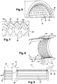
- the figures 4, 5 and 9 represent a male shaft 22, which is the shaft 8 in the above example.
- This shaft comprises external grooves 24 rectilinear which extend over a length denoted L1.
- the shaft 22 further comprises an annular row of external guide teeth 26.
- the outer teeth 26 are axially aligned with the outer splines 24 and have in section transverse shape and dimensions similar to those of the external grooves.
- the grooves 34 have in section a generally trapezoidal shape ( figure 5 ). They each have a flat longitudinal top extending between two preferably flat side flanks, inclined with respect to each other at an angle of between 30 and 80 °. Their longitudinal ends, upstream and downstream respectively, are also bevelled so as to have end faces and end faces inclined with respect to planes perpendicular to the axis of engagement of the splines and passing through these ends ( figure 9 ).
- the teeth 26 here have a length denoted L2 and are axially separated from the grooves 24 by a distance denoted L3.
- the teeth could be obtained by first making splines of length L1 + L2 + L3 then by machining an annular groove 28 of length L2 to separate the final splines from the guide teeth.
- the unnecessary sections of material can be limited.
- the section at the bottom of the groove 28 can be limited to the minimum sufficient to hold the teeth 26.
- the section S1 at the bottom of the groove is for example at least two times smaller than the section S2 at the bottom of the inter-groove groove which it must absorb the torque to be transmitted ( figure 8 ).
- the internal teeth 26 have chamfered peripheral edges 30 on the side opposite the internal splines 24, which further facilitate the respective positioning of the shafts.
- the chamfered edges 30 are advantageously connected to the adjacent surfaces, and in particular to the end faces 26a of the teeth, by fillets 26b in order to eliminate the sharp edges and limit the risks of damage by contact.
- the fillets 26b are in the form of convex roundings ( figure 5 ).
- the teeth have their upstream ends bevelled so that their end faces 26a are inclined with respect to a plane perpendicular to the axis of engagement of the splines ( figure 9 ).
- the downstream ends are here not bevelled and include end faces perpendicular to the axis of engagement.
- the angles of the chamfers are determined to favor the positioning of the parts during the fitting operation.
- the length and shape of the chamfers, as well as the shape of the front face 26a of the teeth 26 makes it possible to maximize the probability of engagement of the positioning teeth with respect to each other. others without frontal impact.
- the figures 6 and 7 represent a female shaft 32, which is the solar of the reducer or a shaft integral with the solar, in the above example.
- This shaft comprises rectilinear internal grooves 34 which extend over a length denoted L4.
- the shaft further comprises an annular row of internal guide teeth 36.
- the internal teeth 36 are axially aligned with the internal splines 34 and have in cross section a shape and dimensions similar to those of the external splines.
- the grooves 34 have in section a generally trapezoidal shape ( figure 7 ). They each have a flat longitudinal top extending between two preferably flat side flanks, inclined with respect to each other at an angle of between 30 and 80 °. Their longitudinal ends, upstream and downstream respectively, are also bevelled so as to have end faces and end faces inclined with respect to planes perpendicular to the axis of engagement of the splines and passing through these ends ( figures 8 and 9 ).
- the teeth 36 here have a length denoted L5 and are axially separated from the splines by a distance denoted L6.
- the teeth 36 could be obtained by first making grooves 34 of length L4 + L5 + L6 then by machining an annular groove 38 of length L5 to separate the final splines from the guide teeth.
- the section S3 at the bottom of the groove 38 is for example at least two times smaller than the section S4 at the bottom of the groove between two internal splines 34 which must absorb the torque to be transmitted ( figure 8 ).
- the section S1 at the bottom of the groove 28 is for example at least two times smaller than the section S3 at the bottom of the groove between two external grooves 24 which must absorb the torque to be transmitted.
- the internal teeth 36 have peripheral edges 40 chamfered on the side opposite the internal splines 34, which further facilitate the respective positioning of the shafts.
- the chamfered edges 40 are advantageously connected to the adjacent surfaces, and in particular to the end faces 36a of the teeth, by fillets 36b in order to eliminate the sharp edges and limit the risks of damage by contact.
- the fillets 36b are in the form of convex roundings ( figure 7 ).
- the teeth have their upstream ends bevelled so that their end faces 36a are inclined with respect to a plane perpendicular to the axis of engagement of the splines ( figure 8 ).
- the downstream ends are here not bevelled and include end faces perpendicular to the axis of engagement.
- the angles of the chamfers are determined to favor the positioning of the parts during the fitting operation.
- the length and shape of the chamfers, as well as the shape of the upstream or leading face of the teeth 36 (in a triangle as opposed to the trapezoidal shape of the splines) makes it possible to maximize the probability of engagement of the positioning teeth with each other. compared to others without frontal impact.
- the distance or length L2 is less than the length L4, and the distance or length L5 is less than the length L1. This prevents the teeth of a shaft from being free to turn. in the groove of the other shaft, located between the teeth and the splines of this other shaft.
- L2 is not necessarily less than L4 and L5 is not necessarily less than L1.
- the figure 8 shows an assembly step by inserting the shafts 22, 32.
- the shafts are aligned and then are engaged one in the other.
- the teeth 26, 36 of the shafts can cooperate by pressing and sliding their chamfered edges 30, 40 until they are positioned to allow their engagement with one another.
- the splines 24, 34 of the shafts are then aligned axially so as to be able to be fitted into one another without risk of contact, and the shafts can be moved one inside the other to their coupling position. In this position, the splines cooperate with each other in an axial coupling zone denoted Z, which has a length overall of the order of L1 or L4 ( figure 9 ).
- the teeth 24, 34 are located outside this zone and do not participate in the transmission of torque. Even if they were damaged during assembly, there is therefore no risk of them generating cracks or cracks due to the fact that they are axially distant from zone Z.
- the number of teeth 24, 34 of the shaft 22, 32 is identical to the number of teeth of the other shaft.
- the shafts 22 ', 32' have a number of teeth 26 ', 36' less than the number of their splines.
- the inner shaft 22 ' has a number of teeth 26' less than the number of its splines and the number of teeth 36 'of the outer shaft 32'.
- the shaft 22 ' comprises an annular row of teeth 26' regularly spaced from each other by a pitch equal to twice the pitch between its splines.
- the outer shaft 32 ' has a number of teeth 36' less than the number of its splines 34 '.
- the shaft 32 ′ here comprises an annular row of pairs of consecutive teeth 36 ′, the teeth of each pair delimiting between them a space for the passage of a tooth 26 ′ of the other shaft.
- the pitch between the teeth 36 'of each pair is equal to the pitch between the splines 34' of the same shaft.
- the splines 24, 34 are configured to transmit a large torque between the shafts.
- Limiting the number of teeth 26 ', 36' makes it possible to reduce the impact of the presence of the teeth on the mass of the shafts 22 ', 32'. Excess teeth can be removed from a shaft by machining, for example. Furthermore, in the case of the outer shaft, as only part of the teeth of each pair is intended to cooperate with a tooth of the other shaft, which is intended to pass between the teeth of the pair, these teeth 36 ' can be partly removed to further lighten the shaft 32 '. In the example shown, only one half of the teeth 36 'of each pair is retained.
- the figures 11 and 12 show that, regardless of the angular position of the shafts with respect to each other, there will always be a series of teeth of the inner shaft which will pass between teeth of a pair of teeth of the outer shaft .
- the shafts have been represented very schematically by spacing them radially from one another in an exaggerated manner, for greater clarity. These figures are essentially useful for assessing the number and distribution of teeth as well as their distributions around the axis of the turbomachine.
- each shaft comprises 24 splines. This number is of course not limiting.
- the number of teeth 26 ', 36' is not limiting either.
- the pitch between the teeth strongly depends on the number of teeth of the splines.
- the number of teeth 26 ', 36' can be advantageously arranged so as to always have at least three distinct contacts between these rows of teeth during assembly, regardless of the relative angular position of the shafts at the start of assembly. For example, if we have a spline of more than 150 or 200 teeth, we could imagine having pitches representing the size of 5, 6 teeth or more.
- the aforementioned steps make it possible to assemble the fan module of the turbomachine, which includes the low pressure compressor module and the reduction module. This module is then attached to a module including the high pressure body and then to another module including the low pressure turbine and the low pressure shaft.
- the coupling system described in the foregoing can be used for coupling several pairs of shafts of a turbomachine.
Landscapes
- Engineering & Computer Science (AREA)
- General Engineering & Computer Science (AREA)
- Mechanical Engineering (AREA)
- Chemical & Material Sciences (AREA)
- Combustion & Propulsion (AREA)
- Turbine Rotor Nozzle Sealing (AREA)
- Structures Of Non-Positive Displacement Pumps (AREA)
- Shafts, Cranks, Connecting Bars, And Related Bearings (AREA)
- Organic Low-Molecular-Weight Compounds And Preparation Thereof (AREA)
Claims (12)
- Wellenanordnung (22, 32) für eine Turbomaschine (1) eines Luftfahrzeugs, umfassend eine äußere erste Welle (32) und eine innere zweite Welle (22), wobei die äußere erste Welle dazu vorgesehen ist, auf der zweiten Welle axial in Eingriff genommen zu werden und innere Längsnuten (34) zur Kopplung mit äußeren Längsnuten (24) der zweiten Welle umfasst, dadurch gekennzeichnet, dass:- die erste Welle, in Bezug auf die Eingriffsrichtung den inneren Nuten vorgelagert, eine ringförmige Reihe von inneren Führungszähnen (36) umfasst, wobei die inneren Zähne axial mit inneren Nuten ausgerichtet sind und im Querschnitt eine Form und ähnliche Dimensionen aufweisen wie die der inneren Nuten, und- die zweite Welle, in Bezug auf die Eingriffsrichtung den äußeren Nuten vorgelagert, eine ringförmige Reihe von äußeren Führungszähnen (26) umfasst, wobei die äußeren Zähne axial mit äußeren Nuten ausgerichtet sind und im Querschnitt eine Form und ähnliche Dimensionen aufweisen wie die der äußeren Nuten,und dadurch, dass, wenn die erste und die zweite Welle in einer Kopplungsposition sind, die inneren und die äußeren Nuten im Eingriff miteinander stehen und in einem axialen Kopplungsbereich (Z) zusammenwirken, wobei sich die inneren und die äußeren Zähne außerhalb dieses Kopplungsbereichs befinden.
- Anordnung nach Anspruch 1, wobei während des Einbaus der ersten und der zweiten Welle ineinander deren Zähne so konfiguriert sind, um zu Beginn des Einbaus durch Aufliegen und Gleiten miteinander zusammenzuwirken, um die axiale Ausrichtung der Wellen und ihrer Nuten sicherzustellen und um zu verhindern, dass axiale Enden gegenüber den Nuten aneinander anstoßen.
- Anordnung nach Anspruch 1 oder 2, wobei die inneren Zähne (36) axial von den inneren Nuten (34) der ersten Welle (32) um einen Abstand (L6) getrennt sind, der kleiner ist als die axiale Dimension (L2) der äußeren Zähne (26) und/oder die äußeren Zähne (26) axial von den äußeren Nuten (24) der zweiten Welle (22) um einen Abstand (L3) getrennt sind, der kleiner ist als die axiale Dimension (L5) der inneren Zähne (36).
- Anordnung nach einem der Ansprüche 1 bis 3, wobei die inneren Zähne (36) abgefaste Umfangsränder (40) an der den inneren Nuten (34) entgegengesetzten Seite umfassen und/oder die äußeren Zähne (26) abgefaste Umfangsränder (30) an der den äußeren Nuten (24) entgegengesetzten Seite umfassen.
- Anordnung nach einem der Ansprüche 1 bis 4, wobei mindestens eine der Wellen (22, 32) eine Anzahl von Zähnen (26, 36) umfasst, die identisch mit der Anzahl ihrer Nuten (24, 34) ist.
- Anordnung nach einem der Ansprüche 1 bis 4, wobei mindestens eine der Wellen (22', 32') eine Anzahl von Zähnen (26', 36') umfasst, die kleiner als die Anzahl ihrer Nuten (34') ist.
- Anordnung nach Anspruch 6, wobei eine der Wellen (22') eine Anzahl von Zähnen (26') umfasst, die kleiner ist als die Anzahl von Zähnen (36') der anderen der Wellen (32').
- Anordnung nach Anspruch 6 oder 7, wobei eine der Wellen (22') eine ringförmige Reihe von Zähnen (26') umfasst, die in regelmäßiger Teilung, die gleich dem Doppelten der Teilung zwischen ihren Nuten ist, voneinander beabstandet sind.
- Anordnung nach Anspruch 8, wobei die andere der Wellen (32') eine ringförmige Reihe von Paaren von Zähnen (36') umfasst, wobei die Zähne von jedem Paar untereinander einen Durchgangsraum eines Zahns (26') der anderen Welle (22') begrenzen.
- Turbomaschine (10) eines Luftfahrzeugs, umfassend mindestens eine Anordnung nach einem der vorstehenden Ansprüche.
- Turbomaschine nach Anspruch 10, wobei die erste und die zweite Welle ein Sonnenrad eines Untersetzungsgetriebes und eine Niederdruckwelle, oder zwei Niederdruckwellen sind.
- Verfahren zum Zusammenbauen einer Turbomaschine nach Anspruch 11, umfassend die Schritte, die aus Folgendem bestehen:- Ausrichten der Wellen (22, 32) zueinander,- Annähern der Wellen zueinander derart, dass die Zähne (26, 36) der Wellen durch Aufliegen und Gleiten zusammenwirken, bis sie positioniert sind, um deren Eingriff ineinander zu ermöglichen und die Nuten (24, 34) der Wellen derart axial ausgerichtet sind, dass die einander eingefügt werden können, ohne die Gefahr, sich zu berühren, und- Verschieben der Wellen ineinander bis zu deren Kopplungsposition, wobei die Nuten in einem axialen Kopplungsbereich (Z) miteinander zusammenwirken, wobei sich die Zähne (24, 34) außerhalb dieses Bereichs befinden und folglich nicht dazu vorgesehen sind, an der Übertragung eines Drehmoments zwischen den Wellen mitzuwirken.
Applications Claiming Priority (2)
| Application Number | Priority Date | Filing Date | Title |
|---|---|---|---|
| FR1763051A FR3075879B1 (fr) | 2017-12-22 | 2017-12-22 | Ensemble d'arbres pour une turbomachine d'aeronef |
| PCT/FR2018/053444 WO2019122741A1 (fr) | 2017-12-22 | 2018-12-20 | Ensemble d'arbres pour une turbomachine d'aéronef |
Publications (2)
| Publication Number | Publication Date |
|---|---|
| EP3728792A1 EP3728792A1 (de) | 2020-10-28 |
| EP3728792B1 true EP3728792B1 (de) | 2021-10-13 |
Family
ID=61521698
Family Applications (1)
| Application Number | Title | Priority Date | Filing Date |
|---|---|---|---|
| EP18842432.9A Active EP3728792B1 (de) | 2017-12-22 | 2018-12-20 | Wellenanordnung für ein flugtriebwerk |
Country Status (5)
| Country | Link |
|---|---|
| US (1) | US11661970B2 (de) |
| EP (1) | EP3728792B1 (de) |
| CN (1) | CN111542681B (de) |
| FR (1) | FR3075879B1 (de) |
| WO (1) | WO2019122741A1 (de) |
Families Citing this family (7)
| Publication number | Priority date | Publication date | Assignee | Title |
|---|---|---|---|---|
| FR3098240B1 (fr) * | 2019-07-03 | 2021-07-16 | Safran Aircraft Engines | Agencement de turbomachines d’aeronautique comprenant une pompe de lubrification entrainee par deux engrenages d’angle droit |
| FR3098547B1 (fr) * | 2019-07-08 | 2022-04-29 | Safran Aircraft Engines | Assemblage de maintien d’un train d’engrenages dans une turbomachine |
| US12097897B2 (en) | 2020-09-11 | 2024-09-24 | Steering Solutions Ip Holding Corporation | Intermediate shaft axial retention device |
| FR3115558B1 (fr) * | 2020-10-27 | 2023-12-15 | Safran Aircraft Engines | Dispositif de pressurisation d’une enceinte aval de turbomachine et turbomachine correspondante. |
| FR3148270B1 (fr) * | 2023-04-26 | 2026-04-24 | Renault | Dispositif de transmission de couple entre un générateur de couple et un adaptateur de couple, notamment pour véhicule automobile |
| CN116906458A (zh) * | 2023-07-17 | 2023-10-20 | 江苏新日电动车股份有限公司 | 两端配合式飞轮花键联接结构及电动自行车 |
| FR3162797A1 (fr) * | 2024-06-03 | 2025-12-05 | Safran Aircraft Engines | Turbomachine comprenant plusieurs modules et un dispositif de blocage de ces modules, et procede de montage correspondant |
Family Cites Families (22)
| Publication number | Priority date | Publication date | Assignee | Title |
|---|---|---|---|---|
| DE1026134B (de) * | 1953-01-12 | 1958-03-13 | Fritz Ungerer Dipl Ing | Vorrichtung zur loesbaren Sicherung von Raedern gegen Axialverschiebung |
| US4348956A (en) * | 1980-08-29 | 1982-09-14 | The United States Of America As Represented By The Secretary Of The Army | Artillery shell comprising two sections having complementary coupling members for connecting the sections together |
| DE4332485C1 (de) * | 1993-09-24 | 1995-04-06 | Supervis Ets | Vorrichtung zum Verbinden eines kerbverzahnten, der Übertragung von Drehmomenten dienenden Wellenzapfens |
| US5533825A (en) * | 1994-11-14 | 1996-07-09 | General Electric Company | Parabolically helical spline shaft coupling |
| DE19517258A1 (de) * | 1995-05-11 | 1996-11-14 | Alpha Getriebebau Gmbh | Wellen-Befestigung |
| US6482094B2 (en) * | 2001-03-16 | 2002-11-19 | Schenck Rotec Gmbh | Self-aligning splined male shaft head and engagement method |
| DE10316155B4 (de) * | 2002-05-24 | 2006-04-20 | Sew-Eurodrive Gmbh & Co. Kg | Welle, Baureihe von Wellen und Verfahren zur Fertigung |
| DE10239393A1 (de) * | 2002-08-28 | 2004-03-11 | Zf Friedrichshafen Ag | Welle-Nabe-Verbindung |
| RU2273749C1 (ru) | 2004-08-26 | 2006-04-10 | Открытое акционерное общество "Научно-производственное объединение "Сатурн" (ОАО "НПО "Сатурн") | Узел соединения роторов компрессора и турбины газотурбинного двигателя |
| BRPI0517289B1 (pt) * | 2005-01-03 | 2018-02-27 | Gkn Driveline International Gmbh | Conexão de eixo e cubo, com sistema de segurança |
| JP2006258254A (ja) * | 2005-03-18 | 2006-09-28 | Ntn Corp | 等速ジョイントのシャフト抜け防止構造 |
| FR2909146B1 (fr) | 2006-11-28 | 2009-06-05 | Snecma Sa | Dispositif de liaison de deux arbres rotatifs, en particulier dans une turbomachine. |
| FR2918726A1 (fr) * | 2007-07-11 | 2009-01-16 | Snecma Sa | Accouplement d'arbres par engrenage a denture droite. |
| GB0818249D0 (en) * | 2008-10-07 | 2008-11-12 | Rolls Royce Plc | Splined couplings |
| US20140116184A1 (en) * | 2012-10-31 | 2014-05-01 | Michael W. Clark | Steering wheel retention assembly |
| US20140119810A1 (en) * | 2012-10-31 | 2014-05-01 | Melvin Lee Tinnin | Steering wheel shaft retention mechanism assembly and service tool |
| US9476459B2 (en) * | 2014-01-07 | 2016-10-25 | Hamilton Sundstrand Corporation | Spline lock shaft locking system |
| US9649933B2 (en) * | 2014-05-08 | 2017-05-16 | Gkn Driveline North America, Inc. | Vehicle power transfer unit (PTU) disconnect assembly |
| US20150323014A1 (en) * | 2014-05-08 | 2015-11-12 | Steering Solutions Ip Holding Corporation | Spline press fit orientation lead in |
| JP6622620B2 (ja) * | 2016-02-24 | 2019-12-18 | 日立オートモティブシステムズ株式会社 | プロペラシャフト及びプロペラシャフトの製造方法 |
| DE102016203188A1 (de) * | 2016-02-29 | 2017-08-31 | Bayerische Motoren Werke Aktiengesellschaft | Welle-Nabe-Verbindung |
| KR20180137766A (ko) * | 2017-06-19 | 2018-12-28 | 현대위아 주식회사 | 차량용 휠 구동 유닛 |
-
2017
- 2017-12-22 FR FR1763051A patent/FR3075879B1/fr not_active Expired - Fee Related
-
2018
- 2018-12-20 CN CN201880084963.0A patent/CN111542681B/zh active Active
- 2018-12-20 WO PCT/FR2018/053444 patent/WO2019122741A1/fr not_active Ceased
- 2018-12-20 EP EP18842432.9A patent/EP3728792B1/de active Active
- 2018-12-20 US US16/954,143 patent/US11661970B2/en active Active
Also Published As
| Publication number | Publication date |
|---|---|
| WO2019122741A1 (fr) | 2019-06-27 |
| US20210164350A1 (en) | 2021-06-03 |
| RU2020121632A (ru) | 2022-01-25 |
| CN111542681B (zh) | 2022-09-20 |
| FR3075879A1 (fr) | 2019-06-28 |
| CN111542681A (zh) | 2020-08-14 |
| FR3075879B1 (fr) | 2019-11-15 |
| RU2020121632A3 (de) | 2022-03-24 |
| CA3085822A1 (en) | 2019-06-27 |
| EP3728792A1 (de) | 2020-10-28 |
| US11661970B2 (en) | 2023-05-30 |
Similar Documents
| Publication | Publication Date | Title |
|---|---|---|
| EP3728792B1 (de) | Wellenanordnung für ein flugtriebwerk | |
| EP3728817B1 (de) | Turboluftstrahltriebwerk mit getriebefan | |
| EP3892895B1 (de) | Mechanisches reduktionsgetriebe für turbotriebwerk eines luftfahrzeugs | |
| EP4034797B1 (de) | Öldrossel zur notschmierung eines bauteils für ein flugzeugtriebwerk | |
| EP4240951B1 (de) | Modularität einer flugzeugturbomaschine | |
| FR3084427A1 (fr) | Dispositif de type reducteur mecanique pour une turbomachine | |
| EP3705705A1 (de) | Mechanisches reduktionsgetriebe für luftfahrzeug-turbotriebwerk | |
| FR3075878B1 (fr) | Dispositif d'accouplement de deux arbres de turbomachine d'aeronef | |
| EP4265940B1 (de) | Mechanisches reduktionsgetriebe für eine flugzeugturbomaschine | |
| FR3108947A1 (fr) | Module a reducteur pour une turbomachine d’aeronef | |
| EP3736428B1 (de) | Versetzte dichtungsnut für keilnutkupplung | |
| EP4336068B1 (de) | Planetenträger für ein reduziergetriebe einer flugzeugturbomaschine | |
| EP4411178B1 (de) | Strömungsmaschine mit einem drehzahlminderer mit durch eine zahnkupplung gekoppelten befestigungsflanschen | |
| CA3085822C (en) | Shaft assembly for an aircraft turbomachine | |
| FR3156497A1 (fr) | Gicleur d’huile pour un reducteur de turbomachine d’aeronef | |
| FR3163978A1 (fr) | Reducteur mecanique pour une turbomachine d’aeronef | |
| WO2026003459A1 (fr) | Reducteur mecanique pour une turbomachine d'aeronef | |
| WO2024256774A1 (fr) | Arbre d'accouplement pour une turbomachine d'aeronef | |
| FR3163981A1 (fr) | Reducteur mecanique pour une turbomachine d’aeronef | |
| FR3151640A1 (fr) | Reducteur mecanique pour une turbomachine |
Legal Events
| Date | Code | Title | Description |
|---|---|---|---|
| STAA | Information on the status of an ep patent application or granted ep patent |
Free format text: STATUS: UNKNOWN |
|
| STAA | Information on the status of an ep patent application or granted ep patent |
Free format text: STATUS: THE INTERNATIONAL PUBLICATION HAS BEEN MADE |
|
| PUAI | Public reference made under article 153(3) epc to a published international application that has entered the european phase |
Free format text: ORIGINAL CODE: 0009012 |
|
| STAA | Information on the status of an ep patent application or granted ep patent |
Free format text: STATUS: REQUEST FOR EXAMINATION WAS MADE |
|
| 17P | Request for examination filed |
Effective date: 20200617 |
|
| AK | Designated contracting states |
Kind code of ref document: A1 Designated state(s): AL AT BE BG CH CY CZ DE DK EE ES FI FR GB GR HR HU IE IS IT LI LT LU LV MC MK MT NL NO PL PT RO RS SE SI SK SM TR |
|
| AX | Request for extension of the european patent |
Extension state: BA ME |
|
| DAV | Request for validation of the european patent (deleted) | ||
| DAX | Request for extension of the european patent (deleted) | ||
| GRAP | Despatch of communication of intention to grant a patent |
Free format text: ORIGINAL CODE: EPIDOSNIGR1 |
|
| STAA | Information on the status of an ep patent application or granted ep patent |
Free format text: STATUS: GRANT OF PATENT IS INTENDED |
|
| INTG | Intention to grant announced |
Effective date: 20210525 |
|
| GRAS | Grant fee paid |
Free format text: ORIGINAL CODE: EPIDOSNIGR3 |
|
| GRAA | (expected) grant |
Free format text: ORIGINAL CODE: 0009210 |
|
| STAA | Information on the status of an ep patent application or granted ep patent |
Free format text: STATUS: THE PATENT HAS BEEN GRANTED |
|
| AK | Designated contracting states |
Kind code of ref document: B1 Designated state(s): AL AT BE BG CH CY CZ DE DK EE ES FI FR GB GR HR HU IE IS IT LI LT LU LV MC MK MT NL NO PL PT RO RS SE SI SK SM TR |
|
| REG | Reference to a national code |
Ref country code: GB Ref legal event code: FG4D Free format text: NOT ENGLISH |
|
| REG | Reference to a national code |
Ref country code: CH Ref legal event code: EP |
|
| REG | Reference to a national code |
Ref country code: DE Ref legal event code: R096 Ref document number: 602018025148 Country of ref document: DE |
|
| REG | Reference to a national code |
Ref country code: IE Ref legal event code: FG4D Free format text: LANGUAGE OF EP DOCUMENT: FRENCH |
|
| REG | Reference to a national code |
Ref country code: AT Ref legal event code: REF Ref document number: 1438334 Country of ref document: AT Kind code of ref document: T Effective date: 20211115 |
|
| REG | Reference to a national code |
Ref country code: SE Ref legal event code: TRGR |
|
| REG | Reference to a national code |
Ref country code: LT Ref legal event code: MG9D |
|
| REG | Reference to a national code |
Ref country code: NL Ref legal event code: MP Effective date: 20211013 |
|
| REG | Reference to a national code |
Ref country code: AT Ref legal event code: MK05 Ref document number: 1438334 Country of ref document: AT Kind code of ref document: T Effective date: 20211013 |
|
| PG25 | Lapsed in a contracting state [announced via postgrant information from national office to epo] |
Ref country code: RS Free format text: LAPSE BECAUSE OF FAILURE TO SUBMIT A TRANSLATION OF THE DESCRIPTION OR TO PAY THE FEE WITHIN THE PRESCRIBED TIME-LIMIT Effective date: 20211013 Ref country code: LT Free format text: LAPSE BECAUSE OF FAILURE TO SUBMIT A TRANSLATION OF THE DESCRIPTION OR TO PAY THE FEE WITHIN THE PRESCRIBED TIME-LIMIT Effective date: 20211013 Ref country code: FI Free format text: LAPSE BECAUSE OF FAILURE TO SUBMIT A TRANSLATION OF THE DESCRIPTION OR TO PAY THE FEE WITHIN THE PRESCRIBED TIME-LIMIT Effective date: 20211013 Ref country code: BG Free format text: LAPSE BECAUSE OF FAILURE TO SUBMIT A TRANSLATION OF THE DESCRIPTION OR TO PAY THE FEE WITHIN THE PRESCRIBED TIME-LIMIT Effective date: 20220113 Ref country code: AT Free format text: LAPSE BECAUSE OF FAILURE TO SUBMIT A TRANSLATION OF THE DESCRIPTION OR TO PAY THE FEE WITHIN THE PRESCRIBED TIME-LIMIT Effective date: 20211013 |
|
| PG25 | Lapsed in a contracting state [announced via postgrant information from national office to epo] |
Ref country code: IS Free format text: LAPSE BECAUSE OF FAILURE TO SUBMIT A TRANSLATION OF THE DESCRIPTION OR TO PAY THE FEE WITHIN THE PRESCRIBED TIME-LIMIT Effective date: 20220213 Ref country code: PT Free format text: LAPSE BECAUSE OF FAILURE TO SUBMIT A TRANSLATION OF THE DESCRIPTION OR TO PAY THE FEE WITHIN THE PRESCRIBED TIME-LIMIT Effective date: 20220214 Ref country code: PL Free format text: LAPSE BECAUSE OF FAILURE TO SUBMIT A TRANSLATION OF THE DESCRIPTION OR TO PAY THE FEE WITHIN THE PRESCRIBED TIME-LIMIT Effective date: 20211013 Ref country code: NO Free format text: LAPSE BECAUSE OF FAILURE TO SUBMIT A TRANSLATION OF THE DESCRIPTION OR TO PAY THE FEE WITHIN THE PRESCRIBED TIME-LIMIT Effective date: 20220113 Ref country code: NL Free format text: LAPSE BECAUSE OF FAILURE TO SUBMIT A TRANSLATION OF THE DESCRIPTION OR TO PAY THE FEE WITHIN THE PRESCRIBED TIME-LIMIT Effective date: 20211013 Ref country code: LV Free format text: LAPSE BECAUSE OF FAILURE TO SUBMIT A TRANSLATION OF THE DESCRIPTION OR TO PAY THE FEE WITHIN THE PRESCRIBED TIME-LIMIT Effective date: 20211013 Ref country code: HR Free format text: LAPSE BECAUSE OF FAILURE TO SUBMIT A TRANSLATION OF THE DESCRIPTION OR TO PAY THE FEE WITHIN THE PRESCRIBED TIME-LIMIT Effective date: 20211013 Ref country code: GR Free format text: LAPSE BECAUSE OF FAILURE TO SUBMIT A TRANSLATION OF THE DESCRIPTION OR TO PAY THE FEE WITHIN THE PRESCRIBED TIME-LIMIT Effective date: 20220114 Ref country code: ES Free format text: LAPSE BECAUSE OF FAILURE TO SUBMIT A TRANSLATION OF THE DESCRIPTION OR TO PAY THE FEE WITHIN THE PRESCRIBED TIME-LIMIT Effective date: 20211013 |
|
| REG | Reference to a national code |
Ref country code: DE Ref legal event code: R097 Ref document number: 602018025148 Country of ref document: DE |
|
| PG25 | Lapsed in a contracting state [announced via postgrant information from national office to epo] |
Ref country code: SM Free format text: LAPSE BECAUSE OF FAILURE TO SUBMIT A TRANSLATION OF THE DESCRIPTION OR TO PAY THE FEE WITHIN THE PRESCRIBED TIME-LIMIT Effective date: 20211013 Ref country code: SK Free format text: LAPSE BECAUSE OF FAILURE TO SUBMIT A TRANSLATION OF THE DESCRIPTION OR TO PAY THE FEE WITHIN THE PRESCRIBED TIME-LIMIT Effective date: 20211013 Ref country code: RO Free format text: LAPSE BECAUSE OF FAILURE TO SUBMIT A TRANSLATION OF THE DESCRIPTION OR TO PAY THE FEE WITHIN THE PRESCRIBED TIME-LIMIT Effective date: 20211013 Ref country code: MC Free format text: LAPSE BECAUSE OF FAILURE TO SUBMIT A TRANSLATION OF THE DESCRIPTION OR TO PAY THE FEE WITHIN THE PRESCRIBED TIME-LIMIT Effective date: 20211013 Ref country code: EE Free format text: LAPSE BECAUSE OF FAILURE TO SUBMIT A TRANSLATION OF THE DESCRIPTION OR TO PAY THE FEE WITHIN THE PRESCRIBED TIME-LIMIT Effective date: 20211013 Ref country code: DK Free format text: LAPSE BECAUSE OF FAILURE TO SUBMIT A TRANSLATION OF THE DESCRIPTION OR TO PAY THE FEE WITHIN THE PRESCRIBED TIME-LIMIT Effective date: 20211013 Ref country code: CZ Free format text: LAPSE BECAUSE OF FAILURE TO SUBMIT A TRANSLATION OF THE DESCRIPTION OR TO PAY THE FEE WITHIN THE PRESCRIBED TIME-LIMIT Effective date: 20211013 |
|
| REG | Reference to a national code |
Ref country code: CH Ref legal event code: PL |
|
| PLBE | No opposition filed within time limit |
Free format text: ORIGINAL CODE: 0009261 |
|
| STAA | Information on the status of an ep patent application or granted ep patent |
Free format text: STATUS: NO OPPOSITION FILED WITHIN TIME LIMIT |
|
| 26N | No opposition filed |
Effective date: 20220714 |
|
| REG | Reference to a national code |
Ref country code: BE Ref legal event code: MM Effective date: 20211231 |
|
| PG25 | Lapsed in a contracting state [announced via postgrant information from national office to epo] |
Ref country code: IE Free format text: LAPSE BECAUSE OF NON-PAYMENT OF DUE FEES Effective date: 20211220 Ref country code: AL Free format text: LAPSE BECAUSE OF FAILURE TO SUBMIT A TRANSLATION OF THE DESCRIPTION OR TO PAY THE FEE WITHIN THE PRESCRIBED TIME-LIMIT Effective date: 20211013 Ref country code: LU Free format text: LAPSE BECAUSE OF NON-PAYMENT OF DUE FEES Effective date: 20211220 |
|
| PG25 | Lapsed in a contracting state [announced via postgrant information from national office to epo] |
Ref country code: SI Free format text: LAPSE BECAUSE OF FAILURE TO SUBMIT A TRANSLATION OF THE DESCRIPTION OR TO PAY THE FEE WITHIN THE PRESCRIBED TIME-LIMIT Effective date: 20211013 Ref country code: BE Free format text: LAPSE BECAUSE OF NON-PAYMENT OF DUE FEES Effective date: 20211231 |
|
| PG25 | Lapsed in a contracting state [announced via postgrant information from national office to epo] |
Ref country code: LI Free format text: LAPSE BECAUSE OF NON-PAYMENT OF DUE FEES Effective date: 20211231 Ref country code: CH Free format text: LAPSE BECAUSE OF NON-PAYMENT OF DUE FEES Effective date: 20211231 |
|
| PG25 | Lapsed in a contracting state [announced via postgrant information from national office to epo] |
Ref country code: CY Free format text: LAPSE BECAUSE OF FAILURE TO SUBMIT A TRANSLATION OF THE DESCRIPTION OR TO PAY THE FEE WITHIN THE PRESCRIBED TIME-LIMIT Effective date: 20211013 |
|
| PG25 | Lapsed in a contracting state [announced via postgrant information from national office to epo] |
Ref country code: HU Free format text: LAPSE BECAUSE OF FAILURE TO SUBMIT A TRANSLATION OF THE DESCRIPTION OR TO PAY THE FEE WITHIN THE PRESCRIBED TIME-LIMIT; INVALID AB INITIO Effective date: 20181220 |
|
| PG25 | Lapsed in a contracting state [announced via postgrant information from national office to epo] |
Ref country code: MK Free format text: LAPSE BECAUSE OF FAILURE TO SUBMIT A TRANSLATION OF THE DESCRIPTION OR TO PAY THE FEE WITHIN THE PRESCRIBED TIME-LIMIT Effective date: 20211013 |
|
| PG25 | Lapsed in a contracting state [announced via postgrant information from national office to epo] |
Ref country code: TR Free format text: LAPSE BECAUSE OF FAILURE TO SUBMIT A TRANSLATION OF THE DESCRIPTION OR TO PAY THE FEE WITHIN THE PRESCRIBED TIME-LIMIT Effective date: 20211013 |
|
| PG25 | Lapsed in a contracting state [announced via postgrant information from national office to epo] |
Ref country code: MT Free format text: LAPSE BECAUSE OF FAILURE TO SUBMIT A TRANSLATION OF THE DESCRIPTION OR TO PAY THE FEE WITHIN THE PRESCRIBED TIME-LIMIT Effective date: 20211013 |
|
| PGFP | Annual fee paid to national office [announced via postgrant information from national office to epo] |
Ref country code: GB Payment date: 20251229 Year of fee payment: 8 |
|
| PGFP | Annual fee paid to national office [announced via postgrant information from national office to epo] |
Ref country code: FR Payment date: 20251222 Year of fee payment: 8 |
|
| PGFP | Annual fee paid to national office [announced via postgrant information from national office to epo] |
Ref country code: SE Payment date: 20251217 Year of fee payment: 8 |
|
| PGFP | Annual fee paid to national office [announced via postgrant information from national office to epo] |
Ref country code: DE Payment date: 20251222 Year of fee payment: 8 |
|
| PGFP | Annual fee paid to national office [announced via postgrant information from national office to epo] |
Ref country code: IT Payment date: 20251231 Year of fee payment: 8 |