EP4336068B1 - Planetenträger für ein reduziergetriebe einer flugzeugturbomaschine - Google Patents
Planetenträger für ein reduziergetriebe einer flugzeugturbomaschine Download PDFInfo
- Publication number
- EP4336068B1 EP4336068B1 EP23194959.5A EP23194959A EP4336068B1 EP 4336068 B1 EP4336068 B1 EP 4336068B1 EP 23194959 A EP23194959 A EP 23194959A EP 4336068 B1 EP4336068 B1 EP 4336068B1
- Authority
- EP
- European Patent Office
- Prior art keywords
- cage
- bridges
- planet carrier
- axis
- walls
- Prior art date
- Legal status (The legal status is an assumption and is not a legal conclusion. Google has not performed a legal analysis and makes no representation as to the accuracy of the status listed.)
- Active
Links
Images


Classifications
-
- F—MECHANICAL ENGINEERING; LIGHTING; HEATING; WEAPONS; BLASTING
- F16—ENGINEERING ELEMENTS AND UNITS; GENERAL MEASURES FOR PRODUCING AND MAINTAINING EFFECTIVE FUNCTIONING OF MACHINES OR INSTALLATIONS; THERMAL INSULATION IN GENERAL
- F16H—GEARING
- F16H57/00—General details of gearing
- F16H57/08—General details of gearing of gearings with members having orbital motion
- F16H57/082—Planet carriers
-
- F—MECHANICAL ENGINEERING; LIGHTING; HEATING; WEAPONS; BLASTING
- F16—ENGINEERING ELEMENTS AND UNITS; GENERAL MEASURES FOR PRODUCING AND MAINTAINING EFFECTIVE FUNCTIONING OF MACHINES OR INSTALLATIONS; THERMAL INSULATION IN GENERAL
- F16H—GEARING
- F16H1/00—Toothed gearings for conveying rotary motion
- F16H1/28—Toothed gearings for conveying rotary motion with gears having orbital motion
-
- F—MECHANICAL ENGINEERING; LIGHTING; HEATING; WEAPONS; BLASTING
- F02—COMBUSTION ENGINES; HOT-GAS OR COMBUSTION-PRODUCT ENGINE PLANTS
- F02C—GAS-TURBINE PLANTS; AIR INTAKES FOR JET-PROPULSION PLANTS; CONTROLLING FUEL SUPPLY IN AIR-BREATHING JET-PROPULSION PLANTS
- F02C7/00—Features, components parts, details or accessories, not provided for in, or of interest apart form groups F02C1/00 - F02C6/00; Air intakes for jet-propulsion plants
- F02C7/36—Power transmission arrangements between the different shafts of the gas turbine plant, or between the gas-turbine plant and the power user
-
- F—MECHANICAL ENGINEERING; LIGHTING; HEATING; WEAPONS; BLASTING
- F16—ENGINEERING ELEMENTS AND UNITS; GENERAL MEASURES FOR PRODUCING AND MAINTAINING EFFECTIVE FUNCTIONING OF MACHINES OR INSTALLATIONS; THERMAL INSULATION IN GENERAL
- F16H—GEARING
- F16H1/00—Toothed gearings for conveying rotary motion
- F16H1/28—Toothed gearings for conveying rotary motion with gears having orbital motion
- F16H1/2809—Toothed gearings for conveying rotary motion with gears having orbital motion with means for equalising the distribution of load on the planet gears
- F16H1/2827—Toothed gearings for conveying rotary motion with gears having orbital motion with means for equalising the distribution of load on the planet gears by allowing limited movement of the planet carrier, e.g. relative to its shaft
-
- F—MECHANICAL ENGINEERING; LIGHTING; HEATING; WEAPONS; BLASTING
- F05—INDEXING SCHEMES RELATING TO ENGINES OR PUMPS IN VARIOUS SUBCLASSES OF CLASSES F01-F04
- F05D—INDEXING SCHEME FOR ASPECTS RELATING TO NON-POSITIVE-DISPLACEMENT MACHINES OR ENGINES, GAS-TURBINES OR JET-PROPULSION PLANTS
- F05D2260/00—Function
- F05D2260/40—Transmission of power
- F05D2260/403—Transmission of power through the shape of the drive components
- F05D2260/4031—Transmission of power through the shape of the drive components as in toothed gearing
- F05D2260/40311—Transmission of power through the shape of the drive components as in toothed gearing of the epicyclical, planetary or differential type
Definitions
- the present invention relates in particular to a planet carrier for a speed reducer of an aircraft turbomachine.
- the state of the art includes in particular the documents FR-A1-2 987 416 , FR-A1-2 853 382 , FR-A1-3 041 054 , FR-A1-3 052 213 , FR-A1-3 073 915 , FR-A1-3 084 428 , US-A-5,466,198 , DE-U1-20 208 102232 , EP-A1-4 108 899 , EP-A1- 4 108 900 And EP-A1- 1 945 970 .
- the role of a mechanical reducer is to use a transmission mechanism to modify the speed ratio and torque between an input shaft and an output shaft of the drive mechanism.
- New generations of dual-flow turbomachines particularly those with a high bypass ratio, include a mechanical reducer to drive the shaft of a fan.
- the reducer's purpose is to transform the so-called fast rotation speed of a power turbine shaft into a slower rotation speed for the shaft driving the fan.
- Such a gearbox comprises a central pinion, called a sun gear, a crown gear, and pinions called planet gears, which are meshed between the sun gear and the crown gear.
- the planet gears are held by a frame called a planet carrier.
- the sun gear, the crown gear, and the planet carrier are planet gears because their axes of revolution coincide with the longitudinal axis of the turbomachine.
- the planet gears each have a different axis of revolution and are equally distributed over the same operating diameter around the axis of the planet gears. These axes are parallel to the longitudinal axis of the turbomachine.
- Gearboxes can be composed of one or more meshing stages. This meshing is ensured in different ways such as by contact, friction or even by magnetic field. There are several types of contact meshing such as with straight or herringbone teeth.
- the planet carrier can be a single piece or in the form of a cage and a cage carrier.
- the principle of this second type of cage and cage carrier planet carrier is to maintain the cage in its plane of symmetry in order to balance the recovery of forces on either side of each satellite.
- the cage comprises an internal cavity in which the sun, the satellites and the guide bearings of these satellites are housed.
- the sun comprises internal splines for coupling to a first shaft of the turbomachine and the cage carrier comprises a tubular portion comprising external splines for coupling to another shaft.
- connection of the cage to the cage holder is generally rigid.
- the cage holder comprises an annular row of axial fingers which carry first connecting elements. These first connecting elements cooperate with second connecting elements mounted in housings of the cage to form the flexible connections between the cage holder and the cage, which allow at least one or two degrees of freedom.
- the cage parts each take up a portion of the load.
- the assembly method of the cage parts must allow the transmission of this load to the connections with the cage carrier, and also the resistance to this load.
- the guide bearings of the satellites are carried by the cage and must be perfectly positioned after the parts are assembled to ensure proper operation of the reducer.
- the planet carrier comprises a cage whose walls are connected by bridges.
- the cage comprises two parts, each comprising a wall and half of the bridges.
- the connecting plane of these parts is a median plane of the cage and the planet carrier, that is to say a plane which is located in the middle of the cage and passes through the middle of the satellites and the solar.
- the present invention provides an improvement which provides a simple, effective and economical solution to at least some of the problems mentioned above.
- the attachment of the parts of the planet carrier cage is therefore achieved by clamping the bridges of one of the parts directly to the other of the parts to the extent that the second part can be considered as forming or comprising a fixing flange to the bridges of the first part.
- This attachment allows the transmission of loads in operation.
- the means of fixing the parts of the cage are advantageously sized to resist this load transmission.
- the mounting openings for the satellite bearings are precisely axially aligned and the method of fixing the cage parts ensures this correct positioning and thus the correct operation of the reducer.
- each of the bridges is formed from a single piece and a single block, which guarantees its integrity and its mechanical strength in operation.
- the connecting plane of the parts of the cage and therefore the plane of transmission of forces between these parts is offset to one side of the cage, which is less likely to penalize the operation of the reducer and in particular to alter the meshing of the satellites in operation.
- this allows the fixing holes formed in the bridges to be optionally tapped to directly receive the fixing means by screwing (without the need for nuts). This is not possible in the prior art because the bridge halves do not necessarily have sufficient length for the tapping of their fixing holes.
- the invention further relates to a turbomachine, in particular for an aircraft, comprising a reducer as described above.
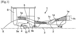
- FIG. 1 describes a turbomachine 1 which comprises, in a conventional manner, a fan S, a low-pressure compressor 1a, a high-pressure compressor 1b, an annular combustion chamber 1c, a high-pressure turbine 1d, a low-pressure turbine 1e and an exhaust nozzle 1h.
- the high-pressure compressor 1b and the high-pressure turbine 1d are connected by a high-pressure shaft 2 and form with it a high-pressure (HP) body.
- the low-pressure compressor 1a and the low-pressure turbine 1e are connected by a low-pressure shaft 3 and form with it a low-pressure (LP) body.
- the blower S is driven by a blower shaft 4 which is connected to the LP shaft 3 by means of a reducer 10.
- This reducer is generally of the planetary or epicyclic type.
- the reducer 10 is positioned in the upstream part of the turbomachine.
- a fixed structure comprising schematically, here, an upstream part 5a and a downstream part 5b which composes the motor casing or stator 5 is arranged so as to form an enclosure E surrounding the reducer 10.
- This enclosure E is here closed upstream by seals at the level of a bearing allowing the crossing of the fan shaft 4, and downstream by seals at the crossing of the LP shaft 3.
- FIG. 1 shows part of a reducer 10 which can take the form of different architectures depending on whether certain parts are fixed or rotating.
- the reducer 10 is connected to the LP shaft 3, for example via splines 7.
- the LP shaft 3 drives a planetary pinion called the sun gear 11.
- the sun gear 11 whose axis of rotation coincides with the X axis of the turbomachine 1, drives a series of pinions called satellites 12, which are equally distributed on the same diameter around the axis of rotation X. This diameter is equal to twice the operating center distance between the sun gear 11 and satellites 12.
- the number of satellites 12 is generally defined between three and seven for this type of application.
- All of the satellites 12 are held by a frame called a planet carrier 13. Each satellite 12 rotates around its own Y axis, and meshes with the crown 14.
- Each satellite 12 is mounted to rotate freely using a bearing 8, for example of the rolling or hydrodynamic type.
- Each bearing 8 is mounted on one of the axes 13a of the planet carrier 13 and all the axes are positioned relative to each other using one or more structural frames of the planet carrier 13. There is a number of axes and bearings equal to the number of satellites 12.
- the half-clamp 14ab of the front crown 14a and the half-clamp 14bb of the rear crown 14b form the crown mounting flange 14c.
- the crown 14 is fixed to the crown carrier 15 by assembling the crown mounting flange 14c and the crown carrier mounting flange 15a using a bolted assembly for example.
- the arrows of the Figure 1 describe the oil routing in the reducer 10.
- the oil arrives in the reducer 10 from the stator part 5 in the distributor 16 by different means which will not be specified in this view because they are specific to one or more types of architecture.
- the distributor 16 is separated into two parts, generally each repeated by the same number of satellites.
- the injectors 17a have the function of lubricating the teeth, and the arms 17b have the function of lubricating the bearings 8.
- the oil is brought towards the injector 17a to exit through the end 17c in order to lubricate the teeth.
- the oil is also supplied to each arm 17b and circulates via the supply port 17d of the bearing 8.
- the oil then circulates through the axis 13a in one or more buffer zones 13b and then exits through orifices 13c in order to lubricate the bearings 8 of the satellites.
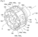
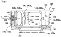
- THE figures 3 to 5 represent a particular technology of planet carrier 113, this planet carrier comprising a cage 120 and a cage carrier 122 connected by flexible connections here with ball joints.
- the cage 120 comprises two radial annular walls 136, 138 which are parallel to each other and perpendicular to the X axis, as well as a cylindrical wall 140 which extends between the external peripheries of these walls 136, 138.
- the cylindrical wall 140 is here of the double-skin type and comprises an external skin 140a interrupted by the slots 143 and an internal skin 140b interrupted by the same slots 143.
- the external skin 140a separated by five slots 143 forms five external or external bridges 140a1
- the internal skin 140b separated by five slots 143 forms five internal or internal bridges 140b1.
- Each pair or couple of internal and external bridges 140a1, 140b1 form a yoke to accommodate one of the fingers 182 of the cage holder 122.
- the bridges 140a1, 140b1 of each pair define between them a housing 180 for receiving a finger 182 of the cage holder 122.
- the bridges 140a1, 140b1 of each pair are aligned radially and define between them this housing.
- cylindrical wall 140 could be single-skinned and each of the bridges 140a1, 140b1 could be hollowed out to form one of said housings 180.
- the bridges 140a1, 140b1 provide the structural connection between the walls 136 and 138.
- the housings 180 open onto the walls 136 and 138, the fingers 182 being engaged in the housings 180 by the openings of the wall 136 in the example shown.
- the cage 120 thus comprises an annular row of housings 180. These housings 180 receive the axial fingers 182 secured to a substantially radial annular wall 182a of the cage holder 122.
- the wall 182a is located at an axial end of the cage holder 122.
- the cage holder 122 comprises a tubular portion 122a which comprises means coupling to a shaft, and for example to the fan shaft 4. These coupling means not shown are for example external splines.
- the fingers 182 extend axially from the wall 182a and are engaged by axial translation in the housings 180.
- Each finger 182 comprises, substantially in its middle, a ring 184 for mounting the ball joint 186 intended to be crossed by a cylindrical pin 188 carried by the cage 120.
- the ring 184 has a substantially radial orientation relative to the axis X. It has a generally cylindrical shape.
- the cage 120 and the ball joint 186 have a thickness, measured in a radial direction relative to the axis X, which is less than the inter-bridge distance or the radial thickness of the oblong slot 180, so as to be able to be engaged in this housing concomitantly with the finger 182 supporting these parts.
- Each housing 180 is crossed by a pin 188 which has a substantially radial orientation relative to the axis X.
- Each pin 188 comprises a cylindrical body 188a connected at an axial end, here radially internal, to an external annular collar 188b.
- the pin 188 is here engaged by radial translation from the inside through radial orifices 141, 143 of the bridges 140a1, 140b1 and of the ball joint 186, its collar 188b being intended to come into radial support on the external bridge 140a1 of the cage 120 in the example shown.
- the collar 188b is fixed to this bridge for example by screwing.
- the walls 136, 138 define between them and with the bridges 140a1, 140b1 an internal cavity of the cage which is configured to receive the solar and the satellites of the reducer.
- the walls 136, 138 include apertures 190 aligned with the axis for mounting the solar.
- each of the walls 136, 138 includes mounting apertures 192 ends of the satellite guide bearings which are inserted into the cavity through the slots 143.
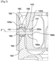
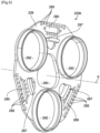
- THE figures 6 And 7 show an embodiment of a cage 220 and its parts 220a, 220b for a planet carrier 213 according to the invention.
- the Figure 6 shows in part this planet carrier 213 which is part of a speed reducer for an aircraft turbomachine.
- the planet carrier 213 comprises a cage 220 and a cage carrier 222 connected by links which allow at least one or two degrees of freedom and which are for example ball joints, as mentioned above.
- the cage carrier 222 is similar to the cage carrier 112 described above and differs from it for example by the number of its fingers 282 which is three in the case of the cage carrier 222, against five in the case of the cage carrier 122.
- the pin connections 288 and ball joints 286 may be similar to those described above.
- the cage holder 222 comprises a tubular portion 222a which comprises means for coupling to a shaft, and for example to the fan shaft 4.
- These coupling means are for example external splines.
- the cage 220 comprises two radial annular walls 236, 238 which are parallel to each other and perpendicular to the X axis, as well as a cylindrical wall 240 which extends between the external peripheries of these walls 236, 238.
- the cylindrical wall 240 is here of the double-skin type and comprises an outer skin 240a interrupted by the slots 243 and an inner skin 240b interrupted by the same slots 243.
- the outer skin 240a separated by three slots 243 forms three outer or external bridges 240a1
- the inner skin 240b separated by three slots 243 forms three inner or internal bridges 240b1.
- Each pair or couple of inner and outer bridges 240a1, 240b1 form a yoke to accommodate one of the fingers 282 of the cage holder 222.
- the bridges 240a1, 240b1 of each pair define between them a housing 280 for receiving a finger 282 of the cage holder 222.
- cylindrical wall 240 could be of the single-skin type and the housings 280 would then be hollowed out or formed in the bridges.
- the bridges provide the structural connection between the walls 236 and 238.
- Elongated or oblong shaped slots are made in or between the bridges 240a1, 240b1 to receive the fingers 282.
- the wall 236 located on the side of the cage holder 222 comprises an external lateral face 236a and an internal lateral face 236b which faces the other wall 238.
- This other wall 238 comprises an internal lateral face 238b which faces the wall 236, and an external lateral face 238a.
- the housings 280 pass axially through the cage 220 and open onto the faces 236a, 238a.
- the walls 236, 238 comprise axially passing openings 290 which are axially aligned with each other and on the axis X.
- the walls 236, 238 comprise axially passing openings 292 which are axially aligned with axially passing openings 292 of the other of the walls. These openings 292 are distributed around the axis X and are intended to receive the axial ends of the bearings (not shown) for guiding the satellites of the reducer, which may be plain bearings or rolling bearings for example.
- the cage 220 comprises a first part 220a and a second part 220b which are fixed together by clamping.
- the first part 220a comprises the wall 236 and the bridges 240a1, 240b1, and in particular all of the bridges.
- These bridges 240a1, 240b1 project axially from the face 236b of the wall 236 and comprise first axial ends 293 connected to this face and second free axial ends 294.
- the second part 220b comprises the wall 238 whose face 238b is applied axially to the free ends 294 of the bridges 240a1, 240b1.
- the free ends 294 of the bridges 240a1, 240b1 each comprise a radial face onto which the housings 280 open. These faces of the bridges 240a1, 240b1 thus comprise outlets 280b of the housings 280.
- These housings 280 are partly formed in the wall 236 which for this purpose comprises through openings 280a aligned with the outlets of the housings 280.
- the transverse shapes and dimensions of the openings 280a are therefore similar to those of the housings 280.
- the fixing means are screws 299 which are visible at the Figure 6
- the screws are mounted through through holes 295 of the wall 238, on the side of the face 238a, and are screwed into tapped holes 296 of the free ends 294 of the bridges 240a1, 240b1.
- the orifices 295 are distributed around the openings 280b. Their number is between 5 and 30 per pair of bridges 240a1, 240b1 and preferably between 10 and 20 per bridge. A portion of the orifices 295 is located radially outside the outlets 280b and another portion of the orifices 295 is located radially inside these outlets 280b.
- the tapped holes 296 are distributed around the openings 280a formed in the wall a. Their number is equal to the number of the orifices 295.
- connecting plane of the parts 220a, 220b is offset relative to the median plane of the cage 220 which passes at the level of the axes of the pins 288.
- the tapped holes 296 extend from the free ends 294 of the bridges to before this median plane, as visible in the Figure 6 .
- the parts 220a, 220b When assembling the cage 220, the parts 220a, 220b are brought axially closer to each other until they are in contact with each other.
- the holes 295 of the part 220b must be aligned with the tapped holes 294 of the part 220a.
- at least one of the parts may comprise centering members configured to cooperate with the other of the parts.
- the centering members comprise curved edges 297 which are carried by one of the parts and which extend around the X axis, these curved edges 297 being configured to cooperate with curved surfaces 298 of the other of the parts.
- the curved edges 297 are carried by the part 220a and are protrusions which extend axially in projection at the level of the free ends 294 of the bridges 240a1, 240b1, and more particularly at the level of the radially external ends of the external bridges 240a1.
- Each of the external bridges 240b1 thus comprises a curved rim 297 projecting axially oriented on the side of the other part 220b.
- Each of these rims 297 is intended to cooperate by axial sliding with a complementary surface 298 of the part 220b and its wall 238.
- each of the edges 297 has an angular extent around the X axis of between 20 and 70°, and preferably between 30 and 50°.
- Each of the surfaces 298 has an angular extent around the X axis of between 20 and 70°, and preferably between 30 and 50°.
- the curved edges 297 are carried by the part 220b and protrude from its face 238b.
- edges 297 are intended to cooperate by axial sliding with complementary surfaces 298 of the free ends 294 of the bridges 240a1, 240b1, and more particularly at the level of the radially internal ends of the internal bridges 240b1.
- each of the edges 297 has an angular extent around the X axis of between 10 and 60°, and preferably between 20 and 40°.
- Each of the surfaces 298 has an angular extent around the X axis of between 10 and 60°, and preferably between 20 and 40°.
- the curved edges 297 are configured to cooperate by radial support with the curved surfaces 298 to allow, if necessary, part of the transmission of forces in the radial direction between the parts 220a, 220b. A major part of these forces is transmitted via the screws 299.
- centering members could be carried by the two parts 220a, 220b or at least one of the parts of the cage 220 could comprise two types of rims 297 such as those of the variant embodiments of the figures 6 , 7 And 8 , 9 .
Landscapes
- Engineering & Computer Science (AREA)
- General Engineering & Computer Science (AREA)
- Mechanical Engineering (AREA)
- Chemical & Material Sciences (AREA)
- Combustion & Propulsion (AREA)
- Retarders (AREA)
- General Details Of Gearings (AREA)
Claims (13)
- Satellitenträger (213) für ein Untersetzungsgetriebe (10) eines Turbotriebwerks (1), wobei dieser Satellitenträger (213) umfasst:- einen Käfigträger (222) mit Hauptachse (X) und einen Kupplungsabschnitt (222a) umfassend, der auf dieser Achse (X) zentriert ist und der axiale Käfigstützfinger (282) aufweist, die um die Achse (X) herum verteilt sind,- einen Käfig (220), der auf der Achse (X) zentriert ist und zwei radial ringförmige Wände (236, 238) umfasst, die durch Brücken (240a1, 240b1) miteinander verbunden sind, die um die Achse (X) herum verteilt sind, wobei die Brücken (240a1, 240b1) sich auf dem externen Umfang der Wände (236, 238) befinden und mit den Wänden (236, 238) einen internen Hohlraum des Käfigs (220) abgrenzen, wobei die Brücken (240a1, 240b1) axiale Aufnahmen (280) umfassen oder definieren, in denen die Finger (282) montiert sind, wobei die Finger (282) über Verbindungen mit den Brücken (240a1, 240b1) verbunden sind, die mindestens einen Freiheitsgrad gestatten, wobei eine der Wände (236) axial durchgehende Öffnungen (292) umfasst, die axial mit den axial durchgehenden Öffnungen (292) der anderen der Wände ausgerichtet sind,dadurch gekennzeichnet, dass der Käfig (220) zwei Stücke (220a, 220b) umfasst:- ein erstes Stück (220a), das eine der Wände (236) und die Brücken (240a1, 240b1) umfasst, wobei diese Brücken (240a1, 240b1) auf einer Fläche (236a) dieser Wand (236) axial hervorstehen und erste axiale Enden (293), die mit dieser Fläche (236a) verbunden sind, und zweite freie axiale Enden (294) umfassen, und- ein zweites Stück (220b), das die andere der Wände (238) umfasst, wobei diese Wand (238) eine Fläche (238a) umfasst, auf der die freien Enden (294) der Brücken (240a1, 240b1) angewendet werden,und dadurch, dass die zwei Stücke (220a, 220b) des Käfigs (220) untereinander durch Befestigungsmittel (299) befestigt sind, die durch die Wand (238) des zweiten Stücks (220b) hindurchgehen und in Befestigungslöcher (296) der Brücken (240a1, 240b1) eingeführt werden.
- Satellitenträger (213) nach Anspruch 1, wobei mindestens eins der Stücke (220a, 220b) des Käfigs (220) Zentrierelemente für das andere der Stücke umfasst, um eine Zentrierung der Stücke in Bezug aufeinander und auf die Achse (X) zu gewährleisten.
- Satellitenträger (213) nach Anspruch 2, wobei die Zentrierelemente gekrümmte Ränder (297) umfassen, die durch eins der Stücke (220a, 220b) getragen werden und die sich um die Achse (X) herum erstrecken, wobei diese gekrümmten Ränder (297) mit den gekrümmten Oberflächen (298) des anderen der Stücke zusammenwirken.
- Satellitenträger (213) nach Anspruch 3, wobei die gekrümmten Ränder (297) Vorsprünge sind, die sich axial hervorstehend erstrecken.
- Satellitenträger (213) nach Anspruch 3 oder 4, wobei die gekrümmten Ränder (297) in der Lage sind, durch axiales Gleiten oder radiales Anliegen mit den gekrümmten Oberflächen zusammenzuwirken.
- Satellitenträger (213) nach einem der Ansprüche 2 bis 5, wobei das erste Stück (220a) Zentrierelemente umfasst, die sich auf den freien Enden (294) der Brücken (240a1, 240b1) an deren radial internen und/oder externen Enden befinden.
- Satellitenträger (213) nach einem der Ansprüche 2 bis 6, wobei das zweite Stück (220b) Zentrierelemente umfasst, die sich auf der Fläche (238b) seiner Wand (238) befinden.
- Satellitenträger (213) nach einem der vorstehenden Ansprüche, wobei das freie Ende (294) von jeder der Brücken (240a1, 240b1) eine Anlagefläche an die vorher genannte Fläche (238b) der Wand (238) des zweiten Stücks (220b) umfasst, wobei die Aufnahme (280) von jeder Brücke (240a1, 240b1) auf dieser Anlagefläche mündet und die Befestigungsbohrungen (296) der Brücken (240a1, 240b1) um die Mündung dieser Aufnahme (280) herum verteilt sind.
- Satellitenträger (213) nach einem der vorstehenden Ansprüche, wobei die Wand (238) des zweiten Stücks (220b) axiale Löcher umfassen, die durch die Wand (238) hindurchgehen und mit den Aufnahmen (280) der Brücken (240a1, 240b1) ausgerichtet sind, wobei die Wand (238) des zweiten Stücks (220b) axiale Bohrungen (295) umfasst, die von den Befestigungsmitteln (299) durchquert werden und die um diese Löcher herum verteilt sind.
- Satellitenträger (213) nach einem der vorstehenden Ansprüche, wobei sich das erste Stück (220a) auf der Seite des Kupplungsabschnitts (222a) des Käfigträgers (222) befindet.
- Satellitenträger (213) nach einem der vorstehenden Ansprüche, wobei die Befestigungsmittel Schrauben sind und die Befestigungslöcher mit einem Gewinde versehen sind, um die Schrauben durch Verschraubung aufzunehmen.
- Untersetzungsgetriebe (10) für ein Turbotriebwerk (1) eines Luftfahrzeugs, wobei dieses Getriebe (10) eine Hauptachse aufweist und Folgendes umfasst:- einen Satellitenträger (213) nach einem der vorstehenden Ansprüche,- ein Sonnenrad (11), das in dem internen Hohlraum des Käfigs (220) angeordnet ist und auf der Achse (X) zentriert ist,- Satelliten (12), die in dem internen Hohlraum um die Achse (X) und das Sonnenrad (11) herum angeordnet sind und mit dem Sonnenrad (11) in Eingriff vorliegen, wobei diese Satelliten (12) durch Lager (8) zentriert und geführt werden, von denen die axialen Enden in den zuvor genannten Öffnungen (292) der Wände montiert sind, und- eine Krone (14), die um die Achse (X) und den Käfig (220) herum angeordnet ist und mit den Satelliten (12) in Eingriff vorliegt.
- Turbotriebwerk (1), insbesondere eines Luftfahrzeugs, das ein Getriebe (10) nach dem vorstehenden Anspruch umfasst.
Applications Claiming Priority (1)
| Application Number | Priority Date | Filing Date | Title |
|---|---|---|---|
| FR2209058A FR3139612B1 (fr) | 2022-09-09 | 2022-09-09 | Porte-satellites pour un reducteur de vitesse d’une turbomachine d’aeronef |
Publications (2)
| Publication Number | Publication Date |
|---|---|
| EP4336068A1 EP4336068A1 (de) | 2024-03-13 |
| EP4336068B1 true EP4336068B1 (de) | 2025-05-14 |
Family
ID=83690477
Family Applications (1)
| Application Number | Title | Priority Date | Filing Date |
|---|---|---|---|
| EP23194959.5A Active EP4336068B1 (de) | 2022-09-09 | 2023-09-01 | Planetenträger für ein reduziergetriebe einer flugzeugturbomaschine |
Country Status (3)
| Country | Link |
|---|---|
| US (1) | US12123479B2 (de) |
| EP (1) | EP4336068B1 (de) |
| FR (1) | FR3139612B1 (de) |
Family Cites Families (13)
| Publication number | Priority date | Publication date | Assignee | Title |
|---|---|---|---|---|
| US5466198A (en) * | 1993-06-11 | 1995-11-14 | United Technologies Corporation | Geared drive system for a bladed propulsor |
| FR2853382B1 (fr) * | 2003-04-04 | 2006-04-28 | Hispano Suiza Sa | Systeme de liaison souple entre un porte-satellites et le support fixe dans un reducteur de vitesse |
| JP4715161B2 (ja) * | 2004-10-26 | 2011-07-06 | アイシン・エィ・ダブリュ株式会社 | プラネタリギヤ装置 |
| DE102005054088A1 (de) * | 2005-11-12 | 2007-05-16 | Mtu Aero Engines Gmbh | Planetengetriebe |
| US8667688B2 (en) * | 2006-07-05 | 2014-03-11 | United Technologies Corporation | Method of assembly for gas turbine fan drive gear system |
| FR2987416B1 (fr) | 2012-02-23 | 2015-09-04 | Snecma | Dispositif de lubrification d'un reducteur epicycloidal. |
| FR3041054B1 (fr) | 2015-09-15 | 2017-09-15 | Hispano-Suiza | Dispositif d'alimentation en huile pour un reducteur a train epicycloidal. |
| FR3052213B1 (fr) | 2016-06-07 | 2018-05-18 | Safran Transmission Systems | Procede d'assemblage d'un porte-satellites |
| FR3073915B1 (fr) | 2017-11-17 | 2019-10-25 | Safran Transmission Systems | Cage de reducteur de vitesse a train planetaire ou epicycloidal de turbomachine |
| DE202018102232U1 (de) * | 2018-04-20 | 2019-07-23 | Hofer Powertrain Gmbh | Mittelstegkonzept bei einem Räderumlaufgetriebe wie einem Planetengetriebe |
| FR3084428B1 (fr) | 2018-07-26 | 2020-09-11 | Safran Trans Systems | Cage de reducteur de vitesse a train planetaire ou epicycloidal de turbomachine |
| FR3124564B1 (fr) * | 2021-06-24 | 2023-07-21 | Safran Trans Systems | Porte-satellites pour un reducteur de vitesse de turbomachine d’aeronef |
| FR3124565B1 (fr) * | 2021-06-24 | 2023-07-14 | Safran Trans Systems | Porte-satellites pour un reducteur de vitesse de turbomachine d’aeronef |
-
2022
- 2022-09-09 FR FR2209058A patent/FR3139612B1/fr active Active
-
2023
- 2023-09-01 EP EP23194959.5A patent/EP4336068B1/de active Active
- 2023-09-06 US US18/461,740 patent/US12123479B2/en active Active
Also Published As
| Publication number | Publication date |
|---|---|
| US20240084876A1 (en) | 2024-03-14 |
| FR3139612A1 (fr) | 2024-03-15 |
| FR3139612B1 (fr) | 2024-10-25 |
| EP4336068A1 (de) | 2024-03-13 |
| US12123479B2 (en) | 2024-10-22 |
Similar Documents
| Publication | Publication Date | Title |
|---|---|---|
| EP3892895B1 (de) | Mechanisches reduktionsgetriebe für turbotriebwerk eines luftfahrzeugs | |
| EP3699458B1 (de) | Einheit mit planetenuntersetzungsgetriebe für ein turbotriebwerk | |
| FR3111400A1 (fr) | Reducteur mecanique de turbomachine d’aeronef | |
| EP3982009B1 (de) | Mechanisches reduktionsgetriebe für turbotriebwerk eines luftfahrzeugs | |
| EP3825580B1 (de) | Versorgung und rückgewinnung von schmieröl in einem mechanischen reduktionsgetriebe für luftfahrzeug-turbotriebwerk | |
| EP4108899B1 (de) | Satellitenträger für ein untersetzungsgetriebe eines turbotriebwerks eines luftfahrzeugs | |
| WO2021058893A1 (fr) | Restricteur d'huile pour la lubrification de secours d'un élément de turbomachine d'aéronef | |
| EP4108900B1 (de) | Satellitenträger für ein untersetzungsgetriebe eines turbotriebwerks eines luftfahrzeugs | |
| EP3657041B1 (de) | Planetenträger für ein untersetzungsgetriebe einer turbomachine eines flugzeuges | |
| EP4336070A1 (de) | Antriebsanordnung für ein mechanisches reduktionsgetriebe einer turbomaschine eines flugzeugs | |
| EP4290097A1 (de) | Planetenträger für ein mechanisches reduktionsgetriebe eines turbotriebwerks eines luftfahrzeugs | |
| EP3699460B1 (de) | Solarelement für ein mechanisches reduktionsgetriebe für luftfahrzeug-turbotriebwerk | |
| EP4336059B1 (de) | Gleitlager für ein mechanisches reduktionsgetriebe eines turbotriebwerks eines luftfahrzeugs | |
| EP4336068B1 (de) | Planetenträger für ein reduziergetriebe einer flugzeugturbomaschine | |
| EP4469698A1 (de) | Planetenträger für ein untersetzungsgetriebe einer flugzeugturbomaschine | |
| FR3132554A1 (fr) | Reducteur de vitesse pour une turbomachine d’aeronef | |
| FR3163978A1 (fr) | Reducteur mecanique pour une turbomachine d’aeronef | |
| WO2026003458A1 (fr) | Reducteur mecanique pour une turbomachine d'aeronef | |
| WO2026003459A1 (fr) | Reducteur mecanique pour une turbomachine d'aeronef | |
| WO2025078752A1 (fr) | Porte-satellites pour un reducteur mecanique de turbomachine d'aeronef, reducteur et turbomachine d'aeronef comprenant celui-ci | |
| WO2026003460A1 (fr) | Porte-satellites pour un reducteur mecanique de turbomachine d'aeronef | |
| WO2025078753A1 (fr) | Porte-satellites pour un reducteur mecanique de turbomachine d'aeronef, reducteur et turbomachine d'aeronef comprenant celui-ci | |
| WO2026003456A1 (fr) | Reducteur mecanique pour une turbomachine d'aeronef | |
| FR3139870A1 (fr) | Ensemble de transmission pour un reducteur mecanique de turbomachine d’aeronef | |
| WO2026003457A1 (fr) | Reducteur mecanique pour une turbomachine d'aeronef |
Legal Events
| Date | Code | Title | Description |
|---|---|---|---|
| PUAI | Public reference made under article 153(3) epc to a published international application that has entered the european phase |
Free format text: ORIGINAL CODE: 0009012 |
|
| STAA | Information on the status of an ep patent application or granted ep patent |
Free format text: STATUS: REQUEST FOR EXAMINATION WAS MADE |
|
| 17P | Request for examination filed |
Effective date: 20230901 |
|
| AK | Designated contracting states |
Kind code of ref document: A1 Designated state(s): AL AT BE BG CH CY CZ DE DK EE ES FI FR GB GR HR HU IE IS IT LI LT LU LV MC ME MK MT NL NO PL PT RO RS SE SI SK SM TR |
|
| GRAP | Despatch of communication of intention to grant a patent |
Free format text: ORIGINAL CODE: EPIDOSNIGR1 |
|
| STAA | Information on the status of an ep patent application or granted ep patent |
Free format text: STATUS: GRANT OF PATENT IS INTENDED |
|
| GRAS | Grant fee paid |
Free format text: ORIGINAL CODE: EPIDOSNIGR3 |
|
| GRAA | (expected) grant |
Free format text: ORIGINAL CODE: 0009210 |
|
| STAA | Information on the status of an ep patent application or granted ep patent |
Free format text: STATUS: THE PATENT HAS BEEN GRANTED |
|
| INTG | Intention to grant announced |
Effective date: 20250313 |
|
| RIN1 | Information on inventor provided before grant (corrected) |
Inventor name: SIMON, ADRIEN LOUIS Inventor name: SEREY, JEAN-PIERRE Inventor name: PTASZYNSKI, PATRICE JULIEN Inventor name: BECK, GUILLAUME JULIEN Inventor name: MOULY, GUILLAUME PIERRE |
|
| AK | Designated contracting states |
Kind code of ref document: B1 Designated state(s): AL AT BE BG CH CY CZ DE DK EE ES FI FR GB GR HR HU IE IS IT LI LT LU LV MC ME MK MT NL NO PL PT RO RS SE SI SK SM TR |
|
| REG | Reference to a national code |
Ref country code: GB Ref legal event code: FG4D Free format text: NOT ENGLISH |
|
| REG | Reference to a national code |
Ref country code: CH Ref legal event code: EP |
|
| REG | Reference to a national code |
Ref country code: IE Ref legal event code: FG4D Free format text: LANGUAGE OF EP DOCUMENT: FRENCH |
|
| REG | Reference to a national code |
Ref country code: DE Ref legal event code: R096 Ref document number: 602023003470 Country of ref document: DE |
|
| REG | Reference to a national code |
Ref country code: NL Ref legal event code: MP Effective date: 20250514 |
|
| PG25 | Lapsed in a contracting state [announced via postgrant information from national office to epo] |
Ref country code: FI Free format text: LAPSE BECAUSE OF FAILURE TO SUBMIT A TRANSLATION OF THE DESCRIPTION OR TO PAY THE FEE WITHIN THE PRESCRIBED TIME-LIMIT Effective date: 20250514 Ref country code: PT Free format text: LAPSE BECAUSE OF FAILURE TO SUBMIT A TRANSLATION OF THE DESCRIPTION OR TO PAY THE FEE WITHIN THE PRESCRIBED TIME-LIMIT Effective date: 20250915 Ref country code: ES Free format text: LAPSE BECAUSE OF FAILURE TO SUBMIT A TRANSLATION OF THE DESCRIPTION OR TO PAY THE FEE WITHIN THE PRESCRIBED TIME-LIMIT Effective date: 20250514 |
|
| PGFP | Annual fee paid to national office [announced via postgrant information from national office to epo] |
Ref country code: DE Payment date: 20250919 Year of fee payment: 3 |
|
| REG | Reference to a national code |
Ref country code: LT Ref legal event code: MG9D |
|
| PG25 | Lapsed in a contracting state [announced via postgrant information from national office to epo] |
Ref country code: GR Free format text: LAPSE BECAUSE OF FAILURE TO SUBMIT A TRANSLATION OF THE DESCRIPTION OR TO PAY THE FEE WITHIN THE PRESCRIBED TIME-LIMIT Effective date: 20250815 Ref country code: NO Free format text: LAPSE BECAUSE OF FAILURE TO SUBMIT A TRANSLATION OF THE DESCRIPTION OR TO PAY THE FEE WITHIN THE PRESCRIBED TIME-LIMIT Effective date: 20250814 |
|
| PG25 | Lapsed in a contracting state [announced via postgrant information from national office to epo] |
Ref country code: NL Free format text: LAPSE BECAUSE OF FAILURE TO SUBMIT A TRANSLATION OF THE DESCRIPTION OR TO PAY THE FEE WITHIN THE PRESCRIBED TIME-LIMIT Effective date: 20250514 Ref country code: PL Free format text: LAPSE BECAUSE OF FAILURE TO SUBMIT A TRANSLATION OF THE DESCRIPTION OR TO PAY THE FEE WITHIN THE PRESCRIBED TIME-LIMIT Effective date: 20250514 |
|
| REG | Reference to a national code |
Ref country code: AT Ref legal event code: MK05 Ref document number: 1795001 Country of ref document: AT Kind code of ref document: T Effective date: 20250514 |
|
| PG25 | Lapsed in a contracting state [announced via postgrant information from national office to epo] |
Ref country code: BG Free format text: LAPSE BECAUSE OF FAILURE TO SUBMIT A TRANSLATION OF THE DESCRIPTION OR TO PAY THE FEE WITHIN THE PRESCRIBED TIME-LIMIT Effective date: 20250514 |
|
| PG25 | Lapsed in a contracting state [announced via postgrant information from national office to epo] |
Ref country code: HR Free format text: LAPSE BECAUSE OF FAILURE TO SUBMIT A TRANSLATION OF THE DESCRIPTION OR TO PAY THE FEE WITHIN THE PRESCRIBED TIME-LIMIT Effective date: 20250514 |
|
| PG25 | Lapsed in a contracting state [announced via postgrant information from national office to epo] |
Ref country code: AT Free format text: LAPSE BECAUSE OF FAILURE TO SUBMIT A TRANSLATION OF THE DESCRIPTION OR TO PAY THE FEE WITHIN THE PRESCRIBED TIME-LIMIT Effective date: 20250514 |
|
| PGFP | Annual fee paid to national office [announced via postgrant information from national office to epo] |
Ref country code: FR Payment date: 20250923 Year of fee payment: 3 |
|
| PG25 | Lapsed in a contracting state [announced via postgrant information from national office to epo] |
Ref country code: RS Free format text: LAPSE BECAUSE OF FAILURE TO SUBMIT A TRANSLATION OF THE DESCRIPTION OR TO PAY THE FEE WITHIN THE PRESCRIBED TIME-LIMIT Effective date: 20250814 |
|
| PG25 | Lapsed in a contracting state [announced via postgrant information from national office to epo] |
Ref country code: IS Free format text: LAPSE BECAUSE OF FAILURE TO SUBMIT A TRANSLATION OF THE DESCRIPTION OR TO PAY THE FEE WITHIN THE PRESCRIBED TIME-LIMIT Effective date: 20250914 |
|
| PG25 | Lapsed in a contracting state [announced via postgrant information from national office to epo] |
Ref country code: LV Free format text: LAPSE BECAUSE OF FAILURE TO SUBMIT A TRANSLATION OF THE DESCRIPTION OR TO PAY THE FEE WITHIN THE PRESCRIBED TIME-LIMIT Effective date: 20250514 |
|
| PG25 | Lapsed in a contracting state [announced via postgrant information from national office to epo] |
Ref country code: DK Free format text: LAPSE BECAUSE OF FAILURE TO SUBMIT A TRANSLATION OF THE DESCRIPTION OR TO PAY THE FEE WITHIN THE PRESCRIBED TIME-LIMIT Effective date: 20250514 Ref country code: SM Free format text: LAPSE BECAUSE OF FAILURE TO SUBMIT A TRANSLATION OF THE DESCRIPTION OR TO PAY THE FEE WITHIN THE PRESCRIBED TIME-LIMIT Effective date: 20250514 |
|
| PG25 | Lapsed in a contracting state [announced via postgrant information from national office to epo] |
Ref country code: CZ Free format text: LAPSE BECAUSE OF FAILURE TO SUBMIT A TRANSLATION OF THE DESCRIPTION OR TO PAY THE FEE WITHIN THE PRESCRIBED TIME-LIMIT Effective date: 20250514 |
|
| PG25 | Lapsed in a contracting state [announced via postgrant information from national office to epo] |
Ref country code: EE Free format text: LAPSE BECAUSE OF FAILURE TO SUBMIT A TRANSLATION OF THE DESCRIPTION OR TO PAY THE FEE WITHIN THE PRESCRIBED TIME-LIMIT Effective date: 20250514 |
|
| PG25 | Lapsed in a contracting state [announced via postgrant information from national office to epo] |
Ref country code: SK Free format text: LAPSE BECAUSE OF FAILURE TO SUBMIT A TRANSLATION OF THE DESCRIPTION OR TO PAY THE FEE WITHIN THE PRESCRIBED TIME-LIMIT Effective date: 20250514 |
|
| PG25 | Lapsed in a contracting state [announced via postgrant information from national office to epo] |
Ref country code: IT Free format text: LAPSE BECAUSE OF FAILURE TO SUBMIT A TRANSLATION OF THE DESCRIPTION OR TO PAY THE FEE WITHIN THE PRESCRIBED TIME-LIMIT Effective date: 20250514 |