EP4265940B1 - Mechanisches reduktionsgetriebe für eine flugzeugturbomaschine - Google Patents
Mechanisches reduktionsgetriebe für eine flugzeugturbomaschine Download PDFInfo
- Publication number
- EP4265940B1 EP4265940B1 EP23168337.6A EP23168337A EP4265940B1 EP 4265940 B1 EP4265940 B1 EP 4265940B1 EP 23168337 A EP23168337 A EP 23168337A EP 4265940 B1 EP4265940 B1 EP 4265940B1
- Authority
- EP
- European Patent Office
- Prior art keywords
- bearings
- bearing
- sun gear
- reducer
- solar
- Prior art date
- Legal status (The legal status is an assumption and is not a legal conclusion. Google has not performed a legal analysis and makes no representation as to the accuracy of the status listed.)
- Active
Links
Images



Classifications
-
- F—MECHANICAL ENGINEERING; LIGHTING; HEATING; WEAPONS; BLASTING
- F16—ENGINEERING ELEMENTS AND UNITS; GENERAL MEASURES FOR PRODUCING AND MAINTAINING EFFECTIVE FUNCTIONING OF MACHINES OR INSTALLATIONS; THERMAL INSULATION IN GENERAL
- F16H—GEARING
- F16H57/00—General details of gearing
- F16H57/08—General details of gearing of gearings with members having orbital motion
-
- F—MECHANICAL ENGINEERING; LIGHTING; HEATING; WEAPONS; BLASTING
- F02—COMBUSTION ENGINES; HOT-GAS OR COMBUSTION-PRODUCT ENGINE PLANTS
- F02C—GAS-TURBINE PLANTS; AIR INTAKES FOR JET-PROPULSION PLANTS; CONTROLLING FUEL SUPPLY IN AIR-BREATHING JET-PROPULSION PLANTS
- F02C7/00—Features, components parts, details or accessories, not provided for in, or of interest apart form groups F02C1/00 - F02C6/00; Air intakes for jet-propulsion plants
- F02C7/36—Power transmission arrangements between the different shafts of the gas turbine plant, or between the gas-turbine plant and the power user
-
- F—MECHANICAL ENGINEERING; LIGHTING; HEATING; WEAPONS; BLASTING
- F02—COMBUSTION ENGINES; HOT-GAS OR COMBUSTION-PRODUCT ENGINE PLANTS
- F02C—GAS-TURBINE PLANTS; AIR INTAKES FOR JET-PROPULSION PLANTS; CONTROLLING FUEL SUPPLY IN AIR-BREATHING JET-PROPULSION PLANTS
- F02C7/00—Features, components parts, details or accessories, not provided for in, or of interest apart form groups F02C1/00 - F02C6/00; Air intakes for jet-propulsion plants
- F02C7/06—Arrangements of bearings; Lubricating
-
- F—MECHANICAL ENGINEERING; LIGHTING; HEATING; WEAPONS; BLASTING
- F16—ENGINEERING ELEMENTS AND UNITS; GENERAL MEASURES FOR PRODUCING AND MAINTAINING EFFECTIVE FUNCTIONING OF MACHINES OR INSTALLATIONS; THERMAL INSULATION IN GENERAL
- F16H—GEARING
- F16H57/00—General details of gearing
- F16H57/08—General details of gearing of gearings with members having orbital motion
- F16H57/082—Planet carriers
-
- F—MECHANICAL ENGINEERING; LIGHTING; HEATING; WEAPONS; BLASTING
- F05—INDEXING SCHEMES RELATING TO ENGINES OR PUMPS IN VARIOUS SUBCLASSES OF CLASSES F01-F04
- F05D—INDEXING SCHEME FOR ASPECTS RELATING TO NON-POSITIVE-DISPLACEMENT MACHINES OR ENGINES, GAS-TURBINES OR JET-PROPULSION PLANTS
- F05D2220/00—Application
- F05D2220/30—Application in turbines
- F05D2220/32—Application in turbines in gas turbines
- F05D2220/323—Application in turbines in gas turbines for aircraft propulsion, e.g. jet engines
-
- F—MECHANICAL ENGINEERING; LIGHTING; HEATING; WEAPONS; BLASTING
- F05—INDEXING SCHEMES RELATING TO ENGINES OR PUMPS IN VARIOUS SUBCLASSES OF CLASSES F01-F04
- F05D—INDEXING SCHEME FOR ASPECTS RELATING TO NON-POSITIVE-DISPLACEMENT MACHINES OR ENGINES, GAS-TURBINES OR JET-PROPULSION PLANTS
- F05D2240/00—Components
- F05D2240/50—Bearings
-
- F—MECHANICAL ENGINEERING; LIGHTING; HEATING; WEAPONS; BLASTING
- F05—INDEXING SCHEMES RELATING TO ENGINES OR PUMPS IN VARIOUS SUBCLASSES OF CLASSES F01-F04
- F05D—INDEXING SCHEME FOR ASPECTS RELATING TO NON-POSITIVE-DISPLACEMENT MACHINES OR ENGINES, GAS-TURBINES OR JET-PROPULSION PLANTS
- F05D2260/00—Function
- F05D2260/40—Transmission of power
- F05D2260/403—Transmission of power through the shape of the drive components
- F05D2260/4031—Transmission of power through the shape of the drive components as in toothed gearing
- F05D2260/40311—Transmission of power through the shape of the drive components as in toothed gearing of the epicyclical, planetary or differential type
-
- F—MECHANICAL ENGINEERING; LIGHTING; HEATING; WEAPONS; BLASTING
- F16—ENGINEERING ELEMENTS AND UNITS; GENERAL MEASURES FOR PRODUCING AND MAINTAINING EFFECTIVE FUNCTIONING OF MACHINES OR INSTALLATIONS; THERMAL INSULATION IN GENERAL
- F16H—GEARING
- F16H57/00—General details of gearing
- F16H57/08—General details of gearing of gearings with members having orbital motion
- F16H2057/085—Bearings for orbital gears
Definitions
- the present invention relates to the field of mechanical reducers for turbomachines, particularly aircraft turbomachines.
- the state of the art includes in particular the documents WO-A1-2010/092263 , FR-A1-2 987 416 , FR-A1-3 008 462 , FR-A1-3 008 463 , FR-A1-3 041 054 , FR-A1-3 095 251 , FR-A1-3 111 390 , FR-A1 -3 111 400 , WO-A1-2017/115795 And DE-A1-10 2019 125052 .
- the role of a mechanical reducer is to modify the speed and torque ratio between the input axis and the output axis of a mechanical system.
- New generations of dual-flow turbomachines particularly those with a high bypass ratio, include a mechanical reducer to drive the shaft of a fan.
- the reducer is intended to transform the so-called fast rotation speed of the shaft of a power turbine into a slower rotation speed for the shaft driving the fan.
- Such a reducer comprises a central pinion, called a sun gear, a crown gear and pinions called satellite gears, which are meshed between the sun gear and the crown gear.
- the satellite gears are held by a frame called a planet carrier.
- the sun gear, the crown gear and the planet carrier are planet gears because their axes of revolution coincide with the longitudinal axis X of the turbomachine.
- the satellite gears each have a different axis of revolution equally distributed over the same operating diameter around the axis of the planet gears. These axes are parallel to the longitudinal axis X.
- Gearboxes can be composed of one or more meshing stages. This meshing is ensured in different ways such as by contact, by friction or by magnetic fields. There are several types of contact meshing such as with straight, helical or herringbone teeth.
- the gear of the satellite that cooperates with the solar is different from the gear of the satellite that cooperates with the crown.
- the gears of a satellite that cooperate respectively with the solar and the crown have different average diameters.
- the solar In operation, the solar is self-centered on the X axis, regardless of the type of toothing of this solar (straight, helical, chevron).
- the solar is naturally positioned between satellites, the number of which is generally greater than or equal to three.
- herringbone toothing allows the pinions to be positioned naturally in the axial direction and does not require the use of axial stops. However, it also does not ensure the centering of the solar in the radial direction.
- the reducer can become significantly misaligned, generating a significant restoring force and therefore significant overloads in the teeth.
- the present invention provides an improvement which makes it possible to respond to all or part of the problems of the prior art, and which is simple, effective and economical.
- the teeth preferably chevron-shaped, allow for self-centering of the solar in operation in the axial direction.
- the addition of one or more solar guide bearings allows it to be centered in the radial direction and avoids the risk of misalignment of the solar.
- the invention further relates to a turbomachine, in particular for an aircraft, comprising a mechanical reducer as described above.
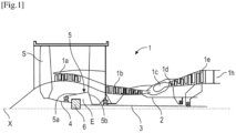
- turbomachine 1 which comprises, in a conventional manner, a fan S, a low-pressure compressor 1a, a high-pressure compressor 1b, an annular combustion chamber 1c, a high-pressure turbine 1d, a low-pressure turbine 1e and an exhaust nozzle 1h.
- the high-pressure compressor 1b and the high-pressure turbine 1d are connected by a high-pressure shaft 2 and form with it a high-pressure (HP) body.
- the low-pressure compressor 1a and the low-pressure turbine 1e are connected by a low-pressure shaft 3 and form with it a low-pressure (LP) body.
- the blower S is driven by a blower shaft 4 which is driven by the LP shaft 3 by means of a reducer 6.
- This reducer 6 is generally of the planetary, epicyclic or even differential type.
- the reducer 6 is positioned in the upstream part of the turbomachine.
- a fixed structure schematically comprising, here, an upstream part 5a and a downstream part 5b which composes the motor casing or stator 5 is arranged so as to form an enclosure E surrounding the reducer 6.
- This enclosure E is here closed upstream by seals at a bearing allowing the fan shaft 4 to pass through, and downstream by seals at the crossing of the LP shaft 3.
- FIG. 2 shows a planetary gear reducer 6.
- the reducer 6 is connected to the BP shaft 3, for example via internal splines 7a.
- the BP shaft 3 drives a planetary pinion called the sun gear 7.
- the sun gear 7, whose axis of rotation coincides with that of the turbomachine X drives a series of pinions called satellites 8, which are equally distributed on the same diameter around the axis of rotation X. This diameter is equal to twice the operating center distance between the sun gear 7 and the satellites 8.
- the number of satellites 8 is generally defined between three and seven for this type of application.
- the set of satellites 8 is held by a frame called a satellite carrier 10.
- Each satellite 8 rotates around its own Y axis, and meshes with the crown 9.
- Each satellite 8 is mounted to rotate freely using a bearing 11, for example of the rolling bearing or hydrodynamic bearing type.
- Each bearing 11 is mounted on one of the axes 10b of the planet carrier 10 and all the axes are positioned relative to each other using one or more structural frames 10a of the planet carrier 10.
- the axes 10b and the frame 10a can be separated into several parts.
- the helix widths vary between the sun gear 7, the satellites 8 and the crown 9 because of the tooth overlaps, they are all centered on a median plane P for the upstream teeth and on another median plane P' for the downstream teeth.
- FIG 2 thus illustrates the case of a single-stage gear reducer, i.e. the same toothing 8d of each satellite 8 cooperates at the same time with the solar 7 and the crown 9. Even if the 8d toothing comprises two series of teeth, these teeth have the same average diameter and form a single toothing called a chevron.
- the half-clamp 9ab of the upstream crown 9a and the half-clamp 9bb of the downstream crown 9b form the fixing flange 9c of the crown.
- the crown 9 is fixed to a crown carrier by assembling the fixing flange 9c of the crown and the fixing flange 12a of the crown carrier using a bolted assembly for example.
- the arrows of the figure 2 describe the routing of the oil in the reducer 6.
- the oil arrives in the reducer 6 from the stator part 5 in a distributor 13 by different means which will not be specified in this view because they are specific to one or more types of architecture.
- the distributor 13 comprises injectors 13a and arms 13b.
- the injectors 13a have the function of lubricating the teeth and the arms 13b have the function of lubricating the bearings.
- the oil is brought to the injector 13a to exit through the end 13c in order to lubricate the teeth.
- the oil is also brought to the arm 13b and circulates via the supply mouth 13d of the bearing.
- the oil then circulates through the axis in one or more buffer zones 10c to then exit through the orifices 10d in order to lubricate the bearings of the satellites.
- each satellite 8 comprises two separate teeth 8d1, 8d2 configured to cooperate respectively with the crown 9 and the sun gear 7.
- the toothing 8d1 meshing with the crown 9 has an average diameter noted D2 and is located in a median plane P.
- the toothing 8d2 meshing with the sun 7 has an average diameter noted D1 and is located in another median plane P'.
- the median planes P, P' are parallel to each other and perpendicular to the X axis.
- the diameter D2 is less than the diameter D1.
- each tooth 8d1, 8d2 here comprises a single helix. These helices not being aligned with each other, unlike chevron teeth, it is necessary to add an axial stop 40.
- This stop 40 is here in the form of a thrust bearing and more particularly a ball bearing.
- THE figures 4 And 5 show another example of reducer architecture, called symmetrical double-stage.
- the plane H is defined as being a median plane perpendicular to the X axis and passing substantially through the middle of the reducer 60 ( figure 5 ).
- the solar 70 comprises internal splines 70a for coupling with the BP shaft 30 as well as external teeth 70b for meshing with the satellites 80.
- the teeth 70b have two series of adjacent teeth in a chevron pattern, separated from each other by an annular groove 72 oriented radially outwards.
- the teeth 70b are symmetrical with respect to the plane H, their teeth being located on either side of the plane H which passes through the groove 72.
- the crown 90 is formed by two independent rings 90a, 90b and comprises a toothing 90d which is separated into two series of teeth 90d1, 90d2 in a chevron pattern carried respectively by the two rings.
- the rings 90a, 90b are arranged symmetrically with respect to the plane H which therefore extends between these rings.
- the rings are connected and fixed to a crown carrier 120 by means of annular connecting flanges 122.
- the flanges 122 are independent of each other, each flange having in axial half-section a general S shape providing it with a certain radial flexibility by elastic deformation in operation.
- Each ring 90a, 90b extends around the axis X and is fixed to the corresponding flange 122 by its external periphery. Its internal periphery comprises one of the teeth 90d1, 90d2.
- the crown carrier 120 has a generally annular shape around the axis X and more particularly biconical. It thus comprises a first upstream section or on the left in the drawing, with an upstream end of smaller diameter, and a downstream end of larger diameter which is connected to the upstream end of larger diameter of the other section, downstream or on the right in the drawing.
- the larger diameter ends of the sections are therefore connected to each other, and their smaller diameter ends form the axial ends of the crown carrier.
- the upstream end of the crown carrier 120 extends around the planet carrier 100 or a shaft connected to this planet carrier, and is centered and guided in rotation on the planet carrier or the shaft by means of at least one bearing 124.
- the downstream end of the crown carrier 120 extends around the planet carrier 100 or a shaft connected to this planet carrier, and is centered and guided in rotation on the planet carrier or the shaft by means of at least one other bearing 126.
- the crown carrier 120 has a symmetry with respect to the plane H which intersects the crown carrier in its middle and therefore passes through the ends of the larger diameter of the aforementioned sections.
- Each satellite 80 comprises a first toothing 82 of average diameter D1 for meshing with the sun gear 70, and a second toothing 84 of average diameter D2, different from D1 and in particular less than D1, for meshing with the crown 90.
- the average diameters are measured from the Y axis of each satellite and represent the average between the maximum diameter and the minimum diameter of a toothing of this satellite.
- Each satellite 80 comprises a cylindrical body 86 and an annular web 88 extending substantially radially outward from the middle of this body 86.
- the toothing 84 is separated into two series of teeth 84d1, 84d2 in a chevron pattern which are located respectively on the axial ends of the body 86.
- the toothing 82 comprises two series of teeth 82d1, 82d2 in a chevron pattern which are located at the external periphery of the web 88 and which are separated from each other by an annular groove 89 opening radially outwards relative to the axis Y.
- the teeth 82 are crossed in their middle by the plane H which passes through the groove 89, the teeth 82d1, 82d2 therefore being arranged on either side of the plane H.
- the teeth 84d1, 84d2 are also arranged symmetrically with respect to the plane H.
- the teeth 82 and the external periphery of the web 88 have an axial dimension which is less than the axial distance between the rings 90a, 90b, as well as between the flanges 122, so that each satellite 80 can freely rotate in the crown carrier 120 and between the rings 90a, 90b and the flanges 122.
- the “symmetry” of the gear teeth of the satellites makes it possible to symmetrize the axial forces as well as the moments to which the satellites are subjected during operation.
- the invention provides an improvement to the technologies described in the foregoing and illustrated in Figures 2 to 5 .
- the invention proposes to add to the mechanical reducer at least one bearing for guiding and centering the solar.
- the reducer already comprises bearings, which can be called first bearings, and which are used for guiding and centering the satellites.
- the reducer according to the invention comprises another or other bearings, which can be called second bearing(s), and which are used for guiding and centering the solar.
- the first and second bearings are different.
- the first and second bearings can all be carried by the planet carrier or mounted in the planet carrier, each of the first bearings extending inside a satellite and the or each of the second bearings preferably extending around the solar and/or at one (or both) axial ends of the solar.
- the reducer may comprise third bearings for guiding the crown carrier relative to the planet carrier.
- FIG 6 illustrates a first embodiment of the invention in the context of a single-stage gear reducer.
- the preceding description made in relation to the figure 2 also applies and concerns the invention to the extent that it is not contrary to the following.
- Figures 7 to 11 illustrate a second embodiment and variants of the invention in the context of a double-stage gear reducer.
- the preceding description made in relation to the figures 4 And 5 also applies and concerns the invention to the extent that it is not contrary to the following.
- Solar 7 of the figure 6 comprises internal splines 7a and external herringbone teeth 7b.
- H1 defines a median plane passing through the middle of the sun 7 and perpendicular to the X axis. H1 passes through the middle of the teeth 7b and through the middle of the splines 7a.
- the teeth 7b are herringbone and comprise two series of teeth, respectively upstream and downstream, which are separated by an external annular groove 7c.
- the series of teeth are symmetrical with respect to the plane H1.
- the solar 7 is centered and guided in rotation around the X axis by two bearings, respectively upstream 200 and downstream 201. These bearings 200, 201 are mounted between the solar 7 and the planet carrier 10, and more precisely between axial extensions 202, 204 of the solar 7 and the planet carrier 10.
- the solar 7 thus comprises an upstream axial extension 202 which is tubular and which comprises an external cylindrical surface 202a on which is mounted an internal ring of the upstream bearing 200.
- the external ring of this bearing 200 is in radial support on a cylindrical rim 10x of the planet carrier. 10.
- This 10x flange extends, for example, in projection from a radial wall of the planet carrier 10.
- the solar 7 comprises a downstream axial extension 204 which is tubular and which comprises an external cylindrical surface 204a on which is mounted an internal ring of the downstream bearing 201.
- the external ring 200b of this bearing 201 is in radial support on a cylindrical rim 10y of the planet carrier 10. This rim 10y borders for example the central orifice of the planet carrier 10 which is crossed by the shaft 3.
- the bearings 200, 201 are identical and the surfaces 202a, 204a have the same diameter D3.
- the bearings 200, 201 are here rolling bearings and more precisely roller bearings.
- each of these bearings allows a degree of freedom of the solar 7 in the axial direction with respect to the planet carrier 10.
- the bearings 200, 201 are at an axial distance L1 from each other, which is less than an axial dimension L2 of the satellites 8 or of their bearings 11.
- the bearings 200, 201 have an internal diameter less than the internal diameter of the toothing 7b of the sun gear 7, and an external diameter greater than the external diameter of the toothing 7b of the sun gear 7.
- the satellites 8 are arranged around these bearings 200, 201.
- the extensions 202, 204 may have a radial thickness E1 less than that of the rest of the solar 7, as illustrated in the drawing.
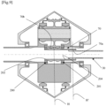
- the solar 70 of the figure 7 comprises internal splines 70a and external herringbone teeth 70b.
- the plane H passes through the middle of the teeth 70b and through the middle of the splines 70a.
- the teeth 70b are herringbone and comprise two series of teeth, respectively upstream and downstream, which are separated by an external annular groove 72.
- the series of teeth are symmetrical with respect to the plane H.
- the solar 70 is centered and guided in rotation around the X axis by two bearings, respectively upstream 200 and downstream 201. These bearings 200, 201 are mounted between the solar 70 and the planet carrier 100, and more precisely between axial extensions 202, 204 of the solar and the planet carrier 100.
- the solar 70 thus comprises an upstream axial extension 202 which is tubular and which comprises an external cylindrical surface 202a on which is mounted an internal ring 200a of the upstream bearing 200.
- the external ring 200b of this bearing 200 is in radial support on a cylindrical rim 100x of the planet carrier 100. This rim 100x extends for example in projection from a radial wall of the planet carrier 100.
- the solar 70 comprises a downstream axial extension 204 which is tubular and which comprises an external cylindrical surface 204a on which an internal ring 201a of the downstream bearing 200 is mounted.
- the external ring 200b of this bearing 201 is in radial support on a cylindrical rim 100y of the planet carrier 10.
- This rim 100y extends for example in projection from a radial wall of the planet carrier 100 and can border for example the central orifice of the planet carrier 100 which is crossed by the shaft 30.
- the bearings 200, 201 are identical and the surfaces 202a, 204a have the same diameter D3.
- the bearings 200, 201 are here rolling bearings and more precisely roller bearings.
- each of these bearings allows a degree of freedom of the solar 70 in the axial direction with respect to the planet carrier 100.
- the bearings 200, 201 are at an axial distance L1 from each other, which is less than an axial dimension L2 of the satellites 80 or of their bearings 110.
- the bearings 200, 201 have an internal diameter less than the internal diameter of the toothing 70b of the sun 70, and an external diameter greater than the external diameter of the toothing 70b of the sun 70.
- the satellites 80 are arranged around these bearings 200, 201.
- the extensions 202, 204 may have a radial thickness E1 less than that of the remainder of the solar 70, as illustrated in the drawing.
- FIG. 7 shows that the bearings 200, 201, which are located on the two opposite axial ends of the solar 70, are located between two other bearings 205, 206, called third bearings, which are used to guide the planet carrier 100 here relative to the crown carrier 120.
- the bearings 200, 201, 205, 206 may be of different types (smooth, rolling, etc.), and are for example with different bearings (rollers, balls, etc.).
- the bearing 205 is a ball bearing and the bearing 206 is a roller bearing.
- the bearings 200, 201, 205, 206 may have different diameters.
- the solar 70 of the figure 8 differs from that of the figure 7 essentially in that its grooves 70a are located at an axial end, here downstream, of the solar 70.
- the bearing 201 is thus located axially between the teeth 70b and the grooves 70a.
- the teeth 70b are crossed by the plane H
- the grooves 70a are crossed by a separate plane H'
- the bearing 201 is located between these planes H, H'.
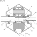
- the solar 70 of the figure 9 differs from that of the figure 8 essentially in that the bearings 200, 201 are plain bearings and not rolling bearings.
- the solar 70 of the figure 10 differs from that of the figure 8 essentially in that the cylindrical surfaces 202a, 204a of the extensions 202, 204 on which the bearings 200, 201 are mounted have different diameters.
- the surface 204a of larger diameter is located downstream and therefore the bearing 201 of larger diameter is located downstream, namely on the side of the shaft 30.
- the inner ring of the bearing 201 is furthermore integrated here into the solar 70 and in particular into the extension 204.
- the solar 70 of the figure 11 differs from that of the figure 10 essentially in that the upstream bearing 200 is absent.
- the solar 70 is therefore centered and guided by a single bearing 201, here downstream, and this solar 70 comprises a single axial extension 204 downstream to support this bearing 201.
Landscapes
- Engineering & Computer Science (AREA)
- General Engineering & Computer Science (AREA)
- Chemical & Material Sciences (AREA)
- Combustion & Propulsion (AREA)
- Mechanical Engineering (AREA)
- Retarders (AREA)
- Rolling Contact Bearings (AREA)
- General Details Of Gearings (AREA)
Claims (15)
- Mechanisches Untersetzungsgetriebe (6, 60) für ein Turbotriebwerk (1), insbesondere eines Luftfahrzeugs, wobei dieses Untersetzungsgetriebe umfasst:- ein Sonnenrad (7, 70), das eine erste Drehachse (X) aufweist, wobei dieses Sonnenrad innere Kerbverzahnungen (7a, 70a) und eine äußere Verzahnung (7b, 70b) umfasst,- einen Kranz (9, 90), der sich um das Sonnenrad (7, 70) herum erstreckt und der eine innere Verzahnung (9d, 90d) umfasst,- Planetenräder (8, 80), die zwischen dem Sonnenrad und dem Kranz angeordnet sind und die jeweils mindestens eine äußere Verzahnung (8d) zum Kämmen mit der äußere Verzahnung des Sonnenrads und der innere Verzahnung des Kranzes umfassen, und- einen Planetenträger (10, 100), der erste Lager (11, 110) zur Drehführung der Planetenräder um zur ersten Achse (X) parallele zweite Achsen (Y) trägt,dadurch gekennzeichnet, dass es weiter mindestens ein zweites Lager (200, 201) zur Drehführung des Sonnenrads (7, 70) umfasst, wobei das mindestens eine zweite Lager (200, 201) zwischen dem Sonnenrad (7, 70) und dem Planetenträger (10, 100) angebracht ist.
- Mechanisches Untersetzungsgetriebe (6, 60) nach Anspruch 1, wobei das Sonnenrad (7, 70) eine erste rohrförmige axiale Verlängerung (202, 204) umfasst, die sich auf einer Seite des Sonnenrads erstreckt und an der das mindestens eine zweite Lager (200, 201) angebracht ist.
- Mechanisches Untersetzungsgetriebe (6, 60) nach Anspruch 2, wobei das Sonnenrad (7, 70) eine zweite rohrförmige axiale Verlängerung (202, 204) umfasst, die sich auf der gegenüberliegenden Seite des Sonnenrads erstreckt und an der ein weiteres zweites Lager (200, 201) angebracht ist.
- Mechanisches Untersetzungsgetriebe (6, 60) nach Anspruch 3, wobei die erste und die zweite Verlängerung (202, 204) zylindrische Außenflächen (202a, 204a) zum Anbringen der zweiten Lager (200, 201) umfassen, die denselben Durchmesser aufweisen.
- Mechanisches Untersetzungsgetriebe (6, 60) nach Anspruch 3, wobei die erste und die zweite Verlängerung (202, 204) zylindrische Außenflächen (202a, 204a) zum Anbringen der zweiten Lager (200, 201a) umfassen, die unterschiedliche Durchmesser aufweisen.
- Mechanisches Untersetzungsgetriebe (6, 60) nach einem der Ansprüche 3 bis 5, wobei sich die zweiten Lager (200, 201) in einem axialen Abstand (L1) zueinander befinden, der kleiner ist als eine axiale Abmessung (L2) der ersten Lager (11) oder der Planetenräder (8, 80).
- Mechanisches Untersetzungsgetriebe (60) nach einem der Ansprüche 1 bis 6, wobei die Kerbverzahnungen (7a, 70a) und die Verzahnung (7b, 70b) des Sonnenrads (7, 70) von derselben Mittelebene (H1, H) durchquert werden, die zur ersten Achse (X) senkrecht steht.
- Mechanisches Untersetzungsgetriebe (6, 60) nach einem der Ansprüche 1 bis 6, wobei die Kerbverzahnungen (7a, 70a) und die Verzahnung (7b, 70b) des Sonnenrads (7, 70) von zwei verschiedenen Ebenen (H1, H2) durchquert werden, die zur ersten Achse (X) senkrecht stehen, wobei sich das mindestens eine zweite Lager (200, 201) oder eines der zweiten Lager axial zwischen diesen zwei Ebenen befindet.
- Mechanisches Untersetzungsgetriebe (6, 60) nach einem der vorstehenden Ansprüche, wobei das mindestens eine zweite Lager (200, 201) ein Wälzlager oder ein Gleitlager ist.
- Mechanisches Untersetzungsgetriebe (6, 60) nach einem der vorstehenden Ansprüche, wobei die Planetenräder (8, 80) um das mindestens eine zweite Lager (200, 201) herum angeordnet sind.
- Mechanisches Untersetzungsgetriebe (6, 60) nach einem der vorstehenden Ansprüche, wobei das mindestens eine zweite Lager (200, 201) eines oder zwei an der Zahl ist.
- Mechanisches Untersetzungsgetriebe (6, 60) nach dem vorstehenden Anspruch, wobei sich die zwei zweiten Lager (200, 201) an zwei gegenüberliegenden axialen Enden des Sonnenrads (7, 70) befinden und sich zwischen zwei dritten Führungslagern (205, 206) des Planetenträgers (10, 100) befinden.
- Mechanisches Untersetzungsgetriebe (6, 60) nach dem vorstehenden Anspruch, wobei die zweiten und die dritten Lager (200, 201, 205, 206) von unterschiedlicher Arten sind und zum Beispiel unterschiedliche Wälzkörper aufweisen.
- Mechanisches Untersetzungsgetriebe (6, 60) nach Anspruch 12 oder 13, wobei die zweiten und die dritten Lager (200, 201, 205, 206) unterschiedliche Durchmesser aufweisen.
- Turbotriebwerk (1), insbesondere eines Luftfahrzeugs, das ein mechanisches Untersetzungsgetriebe (6, 60) nach einem der vorstehenden Ansprüche umfasst.
Applications Claiming Priority (1)
| Application Number | Priority Date | Filing Date | Title |
|---|---|---|---|
| FR2203777A FR3134867B1 (fr) | 2022-04-22 | 2022-04-22 | Reducteur mecanique de turbomachine d’aeronef |
Publications (2)
| Publication Number | Publication Date |
|---|---|
| EP4265940A1 EP4265940A1 (de) | 2023-10-25 |
| EP4265940B1 true EP4265940B1 (de) | 2024-10-09 |
Family
ID=82100679
Family Applications (1)
| Application Number | Title | Priority Date | Filing Date |
|---|---|---|---|
| EP23168337.6A Active EP4265940B1 (de) | 2022-04-22 | 2023-04-17 | Mechanisches reduktionsgetriebe für eine flugzeugturbomaschine |
Country Status (3)
| Country | Link |
|---|---|
| US (1) | US12480451B2 (de) |
| EP (1) | EP4265940B1 (de) |
| FR (1) | FR3134867B1 (de) |
Families Citing this family (1)
| Publication number | Priority date | Publication date | Assignee | Title |
|---|---|---|---|---|
| FR3158338A1 (fr) | 2024-01-12 | 2025-07-18 | Safran Aircraft Engines | Module pour une turbomachine d’aeronef |
Family Cites Families (18)
| Publication number | Priority date | Publication date | Assignee | Title |
|---|---|---|---|---|
| FR2942284B1 (fr) | 2009-02-16 | 2011-03-04 | Snecma | Lubrification et refroidissement d'un reducteur a train d'engrenages epicycloidal |
| US8574118B2 (en) * | 2011-05-31 | 2013-11-05 | United Technologies Corporation | Journal pin for gear system |
| FR2987416B1 (fr) | 2012-02-23 | 2015-09-04 | Snecma | Dispositif de lubrification d'un reducteur epicycloidal. |
| FR3008462B1 (fr) | 2013-07-10 | 2016-12-23 | Hispano Suiza Sa | Integration d'un train d'engrenages dans un voile de pignon de boitier d'entrainement pour turbomachine |
| FR3008463B1 (fr) | 2013-07-10 | 2015-08-07 | Hispano Suiza Sa | Structure compacte de boitier d'entrainement pour turbomachine d'aeronef |
| FR3041054B1 (fr) | 2015-09-15 | 2017-09-15 | Hispano-Suiza | Dispositif d'alimentation en huile pour un reducteur a train epicycloidal. |
| US20190011039A1 (en) | 2015-12-28 | 2019-01-10 | Honda Motor Co., Ltd. | Planetary gear mechanism |
| EP3587768A1 (de) * | 2018-06-27 | 2020-01-01 | Rolls-Royce Deutschland Ltd & Co KG | Gasturbine |
| EP3587773B1 (de) * | 2018-06-27 | 2022-06-08 | Rolls-Royce plc | Gasturbine |
| FR3086343B1 (fr) * | 2018-09-24 | 2020-09-04 | Safran Aircraft Engines | Turbomachine a reducteur pour un aeronef |
| FR3095251B1 (fr) * | 2019-04-16 | 2021-05-07 | Safran Trans Systems | Reducteur mecanique de turbomachine d’aeronef |
| DE102019125052A1 (de) * | 2019-09-18 | 2021-03-18 | Schaeffler Technologies AG & Co. KG | Planetengetriebe mit einem dreistufigen Planeten |
| US11162575B2 (en) * | 2019-11-20 | 2021-11-02 | Raytheon Technologies Corporation | Geared architecture for gas turbine engine |
| FR3104644B1 (fr) * | 2019-12-11 | 2021-11-19 | Safran Aircraft Engines | Système propulsif aéronautique à rendement propulsif amélioré |
| FR3109194B1 (fr) * | 2020-04-10 | 2022-03-18 | Safran Trans Systems | Reducteur mecanique de turbomachine d’aeronef |
| FR3111400B1 (fr) | 2020-06-11 | 2022-05-13 | Safran Trans Systems | Reducteur mecanique de turbomachine d’aeronef |
| FR3111390B1 (fr) | 2020-06-11 | 2022-05-13 | Safran Trans Systems | Reducteur mecanique de turbomachine d’aeronef |
| FR3113934B1 (fr) * | 2020-09-04 | 2022-10-28 | Safran Trans Systems | Reducteur mecanique de turbomachine d’aeronef |
-
2022
- 2022-04-22 FR FR2203777A patent/FR3134867B1/fr active Active
-
2023
- 2023-04-17 EP EP23168337.6A patent/EP4265940B1/de active Active
- 2023-04-21 US US18/305,208 patent/US12480451B2/en active Active
Also Published As
| Publication number | Publication date |
|---|---|
| EP4265940A1 (de) | 2023-10-25 |
| FR3134867B1 (fr) | 2024-05-17 |
| FR3134867A1 (fr) | 2023-10-27 |
| US12480451B2 (en) | 2025-11-25 |
| US20230340912A1 (en) | 2023-10-26 |
Similar Documents
| Publication | Publication Date | Title |
|---|---|---|
| EP3726031B1 (de) | Mechanisches reduktionsgetriebe für luftfahrzeug-turbotriebwerk | |
| EP4001619B1 (de) | Mechanisches getriebe einer luftfahrzeug-turbomaschine | |
| EP3922886B1 (de) | Mechanisches reduktionsgetriebe für turbotriebwerk eines luftfahrzeugs | |
| EP3892895B1 (de) | Mechanisches reduktionsgetriebe für turbotriebwerk eines luftfahrzeugs | |
| EP3995681B1 (de) | Mechanisches reduktionsgetriebe für turbotriebwerk eines luftfahrzeugs | |
| EP3982009B1 (de) | Mechanisches reduktionsgetriebe für turbotriebwerk eines luftfahrzeugs | |
| EP4303468B1 (de) | Sonnenrad für ein reduktionsgetriebe eines turbotriebwerks eines luftfahrzeugs | |
| EP4290097A1 (de) | Planetenträger für ein mechanisches reduktionsgetriebe eines turbotriebwerks eines luftfahrzeugs | |
| EP4336070A1 (de) | Antriebsanordnung für ein mechanisches reduktionsgetriebe einer turbomaschine eines flugzeugs | |
| EP4265940B1 (de) | Mechanisches reduktionsgetriebe für eine flugzeugturbomaschine | |
| EP4471295B1 (de) | Solar für ein mechanisches reduktionsgetriebe eines turbotriebwerks eines luftfahrzeugs | |
| EP4242489B1 (de) | Mechanisches reduktionsgetriebe für flugzeugturbomaschine | |
| EP4093992B1 (de) | Planetenträger für ein mechanisches untersetzungsgetriebe einer flugzeugturbomaschine | |
| WO2024261427A1 (fr) | Turbomachine d'aeronef a double helice de propulsion | |
| WO2026003460A1 (fr) | Porte-satellites pour un reducteur mecanique de turbomachine d'aeronef | |
| FR3158338A1 (fr) | Module pour une turbomachine d’aeronef | |
| FR3139602A1 (fr) | Turbomachine d’aeronef a reducteur mecanique | |
| FR3153867A1 (fr) | Reducteur mecanique de turbomachine d’aeronef | |
| WO2025022052A1 (fr) | Reducteur mecanique pour une turbomachine | |
| WO2026003458A1 (fr) | Reducteur mecanique pour une turbomachine d'aeronef | |
| FR3139870A1 (fr) | Ensemble de transmission pour un reducteur mecanique de turbomachine d’aeronef | |
| WO2026003459A1 (fr) | Reducteur mecanique pour une turbomachine d'aeronef | |
| WO2025022053A1 (fr) | Reducteur mecanique pour une turbomachine |
Legal Events
| Date | Code | Title | Description |
|---|---|---|---|
| PUAI | Public reference made under article 153(3) epc to a published international application that has entered the european phase |
Free format text: ORIGINAL CODE: 0009012 |
|
| STAA | Information on the status of an ep patent application or granted ep patent |
Free format text: STATUS: REQUEST FOR EXAMINATION WAS MADE |
|
| 17P | Request for examination filed |
Effective date: 20230417 |
|
| AK | Designated contracting states |
Kind code of ref document: A1 Designated state(s): AL AT BE BG CH CY CZ DE DK EE ES FI FR GB GR HR HU IE IS IT LI LT LU LV MC ME MK MT NL NO PL PT RO RS SE SI SK SM TR |
|
| STAA | Information on the status of an ep patent application or granted ep patent |
Free format text: STATUS: EXAMINATION IS IN PROGRESS |
|
| 17Q | First examination report despatched |
Effective date: 20240221 |
|
| GRAP | Despatch of communication of intention to grant a patent |
Free format text: ORIGINAL CODE: EPIDOSNIGR1 |
|
| STAA | Information on the status of an ep patent application or granted ep patent |
Free format text: STATUS: GRANT OF PATENT IS INTENDED |
|
| INTG | Intention to grant announced |
Effective date: 20240621 |
|
| GRAS | Grant fee paid |
Free format text: ORIGINAL CODE: EPIDOSNIGR3 |
|
| GRAA | (expected) grant |
Free format text: ORIGINAL CODE: 0009210 |
|
| STAA | Information on the status of an ep patent application or granted ep patent |
Free format text: STATUS: THE PATENT HAS BEEN GRANTED |
|
| AK | Designated contracting states |
Kind code of ref document: B1 Designated state(s): AL AT BE BG CH CY CZ DE DK EE ES FI FR GB GR HR HU IE IS IT LI LT LU LV MC ME MK MT NL NO PL PT RO RS SE SI SK SM TR |
|
| REG | Reference to a national code |
Ref country code: CH Ref legal event code: EP |
|
| REG | Reference to a national code |
Ref country code: DE Ref legal event code: R096 Ref document number: 602023000682 Country of ref document: DE |
|
| REG | Reference to a national code |
Ref country code: IE Ref legal event code: FG4D Free format text: LANGUAGE OF EP DOCUMENT: FRENCH |
|
| REG | Reference to a national code |
Ref country code: LT Ref legal event code: MG9D |
|
| REG | Reference to a national code |
Ref country code: NL Ref legal event code: MP Effective date: 20241009 |
|
| REG | Reference to a national code |
Ref country code: AT Ref legal event code: MK05 Ref document number: 1730908 Country of ref document: AT Kind code of ref document: T Effective date: 20241009 |
|
| PG25 | Lapsed in a contracting state [announced via postgrant information from national office to epo] |
Ref country code: NL Free format text: LAPSE BECAUSE OF FAILURE TO SUBMIT A TRANSLATION OF THE DESCRIPTION OR TO PAY THE FEE WITHIN THE PRESCRIBED TIME-LIMIT Effective date: 20241009 |
|
| PG25 | Lapsed in a contracting state [announced via postgrant information from national office to epo] |
Ref country code: NL Free format text: LAPSE BECAUSE OF FAILURE TO SUBMIT A TRANSLATION OF THE DESCRIPTION OR TO PAY THE FEE WITHIN THE PRESCRIBED TIME-LIMIT Effective date: 20241009 |
|
| PG25 | Lapsed in a contracting state [announced via postgrant information from national office to epo] |
Ref country code: IS Free format text: LAPSE BECAUSE OF FAILURE TO SUBMIT A TRANSLATION OF THE DESCRIPTION OR TO PAY THE FEE WITHIN THE PRESCRIBED TIME-LIMIT Effective date: 20250209 Ref country code: HR Free format text: LAPSE BECAUSE OF FAILURE TO SUBMIT A TRANSLATION OF THE DESCRIPTION OR TO PAY THE FEE WITHIN THE PRESCRIBED TIME-LIMIT Effective date: 20241009 Ref country code: PT Free format text: LAPSE BECAUSE OF FAILURE TO SUBMIT A TRANSLATION OF THE DESCRIPTION OR TO PAY THE FEE WITHIN THE PRESCRIBED TIME-LIMIT Effective date: 20250210 |
|
| PG25 | Lapsed in a contracting state [announced via postgrant information from national office to epo] |
Ref country code: FI Free format text: LAPSE BECAUSE OF FAILURE TO SUBMIT A TRANSLATION OF THE DESCRIPTION OR TO PAY THE FEE WITHIN THE PRESCRIBED TIME-LIMIT Effective date: 20241009 |
|
| PG25 | Lapsed in a contracting state [announced via postgrant information from national office to epo] |
Ref country code: BG Free format text: LAPSE BECAUSE OF FAILURE TO SUBMIT A TRANSLATION OF THE DESCRIPTION OR TO PAY THE FEE WITHIN THE PRESCRIBED TIME-LIMIT Effective date: 20241009 |
|
| PG25 | Lapsed in a contracting state [announced via postgrant information from national office to epo] |
Ref country code: ES Free format text: LAPSE BECAUSE OF FAILURE TO SUBMIT A TRANSLATION OF THE DESCRIPTION OR TO PAY THE FEE WITHIN THE PRESCRIBED TIME-LIMIT Effective date: 20241009 |
|
| PG25 | Lapsed in a contracting state [announced via postgrant information from national office to epo] |
Ref country code: NO Free format text: LAPSE BECAUSE OF FAILURE TO SUBMIT A TRANSLATION OF THE DESCRIPTION OR TO PAY THE FEE WITHIN THE PRESCRIBED TIME-LIMIT Effective date: 20250109 |
|
| PG25 | Lapsed in a contracting state [announced via postgrant information from national office to epo] |
Ref country code: AT Free format text: LAPSE BECAUSE OF FAILURE TO SUBMIT A TRANSLATION OF THE DESCRIPTION OR TO PAY THE FEE WITHIN THE PRESCRIBED TIME-LIMIT Effective date: 20241009 Ref country code: LV Free format text: LAPSE BECAUSE OF FAILURE TO SUBMIT A TRANSLATION OF THE DESCRIPTION OR TO PAY THE FEE WITHIN THE PRESCRIBED TIME-LIMIT Effective date: 20241009 Ref country code: GR Free format text: LAPSE BECAUSE OF FAILURE TO SUBMIT A TRANSLATION OF THE DESCRIPTION OR TO PAY THE FEE WITHIN THE PRESCRIBED TIME-LIMIT Effective date: 20250110 |
|
| PG25 | Lapsed in a contracting state [announced via postgrant information from national office to epo] |
Ref country code: PL Free format text: LAPSE BECAUSE OF FAILURE TO SUBMIT A TRANSLATION OF THE DESCRIPTION OR TO PAY THE FEE WITHIN THE PRESCRIBED TIME-LIMIT Effective date: 20241009 |
|
| PG25 | Lapsed in a contracting state [announced via postgrant information from national office to epo] |
Ref country code: RS Free format text: LAPSE BECAUSE OF FAILURE TO SUBMIT A TRANSLATION OF THE DESCRIPTION OR TO PAY THE FEE WITHIN THE PRESCRIBED TIME-LIMIT Effective date: 20250109 |
|
| PG25 | Lapsed in a contracting state [announced via postgrant information from national office to epo] |
Ref country code: SM Free format text: LAPSE BECAUSE OF FAILURE TO SUBMIT A TRANSLATION OF THE DESCRIPTION OR TO PAY THE FEE WITHIN THE PRESCRIBED TIME-LIMIT Effective date: 20241009 |
|
| PGFP | Annual fee paid to national office [announced via postgrant information from national office to epo] |
Ref country code: DE Payment date: 20250417 Year of fee payment: 3 |
|
| PG25 | Lapsed in a contracting state [announced via postgrant information from national office to epo] |
Ref country code: DK Free format text: LAPSE BECAUSE OF FAILURE TO SUBMIT A TRANSLATION OF THE DESCRIPTION OR TO PAY THE FEE WITHIN THE PRESCRIBED TIME-LIMIT Effective date: 20241009 |
|
| REG | Reference to a national code |
Ref country code: DE Ref legal event code: R097 Ref document number: 602023000682 Country of ref document: DE |
|
| PG25 | Lapsed in a contracting state [announced via postgrant information from national office to epo] |
Ref country code: EE Free format text: LAPSE BECAUSE OF FAILURE TO SUBMIT A TRANSLATION OF THE DESCRIPTION OR TO PAY THE FEE WITHIN THE PRESCRIBED TIME-LIMIT Effective date: 20241009 |
|
| PGFP | Annual fee paid to national office [announced via postgrant information from national office to epo] |
Ref country code: FR Payment date: 20250422 Year of fee payment: 3 |
|
| PG25 | Lapsed in a contracting state [announced via postgrant information from national office to epo] |
Ref country code: RO Free format text: LAPSE BECAUSE OF FAILURE TO SUBMIT A TRANSLATION OF THE DESCRIPTION OR TO PAY THE FEE WITHIN THE PRESCRIBED TIME-LIMIT Effective date: 20241009 |
|
| PG25 | Lapsed in a contracting state [announced via postgrant information from national office to epo] |
Ref country code: SK Free format text: LAPSE BECAUSE OF FAILURE TO SUBMIT A TRANSLATION OF THE DESCRIPTION OR TO PAY THE FEE WITHIN THE PRESCRIBED TIME-LIMIT Effective date: 20241009 |
|
| PG25 | Lapsed in a contracting state [announced via postgrant information from national office to epo] |
Ref country code: CZ Free format text: LAPSE BECAUSE OF FAILURE TO SUBMIT A TRANSLATION OF THE DESCRIPTION OR TO PAY THE FEE WITHIN THE PRESCRIBED TIME-LIMIT Effective date: 20241009 |
|
| PG25 | Lapsed in a contracting state [announced via postgrant information from national office to epo] |
Ref country code: IT Free format text: LAPSE BECAUSE OF FAILURE TO SUBMIT A TRANSLATION OF THE DESCRIPTION OR TO PAY THE FEE WITHIN THE PRESCRIBED TIME-LIMIT Effective date: 20241009 |
|
| PLBE | No opposition filed within time limit |
Free format text: ORIGINAL CODE: 0009261 |
|
| STAA | Information on the status of an ep patent application or granted ep patent |
Free format text: STATUS: NO OPPOSITION FILED WITHIN TIME LIMIT |
|
| PG25 | Lapsed in a contracting state [announced via postgrant information from national office to epo] |
Ref country code: SE Free format text: LAPSE BECAUSE OF FAILURE TO SUBMIT A TRANSLATION OF THE DESCRIPTION OR TO PAY THE FEE WITHIN THE PRESCRIBED TIME-LIMIT Effective date: 20241009 |
|
| 26N | No opposition filed |
Effective date: 20250710 |
|
| PG25 | Lapsed in a contracting state [announced via postgrant information from national office to epo] |
Ref country code: LU Free format text: LAPSE BECAUSE OF NON-PAYMENT OF DUE FEES Effective date: 20250417 |
|
| PG25 | Lapsed in a contracting state [announced via postgrant information from national office to epo] |
Ref country code: MC Free format text: LAPSE BECAUSE OF FAILURE TO SUBMIT A TRANSLATION OF THE DESCRIPTION OR TO PAY THE FEE WITHIN THE PRESCRIBED TIME-LIMIT Effective date: 20241009 |
|
| REG | Reference to a national code |
Ref country code: BE Ref legal event code: MM Effective date: 20250430 |
|
| PG25 | Lapsed in a contracting state [announced via postgrant information from national office to epo] |
Ref country code: BE Free format text: LAPSE BECAUSE OF NON-PAYMENT OF DUE FEES Effective date: 20250430 |
|
| PG25 | Lapsed in a contracting state [announced via postgrant information from national office to epo] |
Ref country code: IE Free format text: LAPSE BECAUSE OF NON-PAYMENT OF DUE FEES Effective date: 20250417 |