EP3727992B1 - Mobile support assembly for holding and transporting a container - Google Patents
Mobile support assembly for holding and transporting a container Download PDFInfo
- Publication number
- EP3727992B1 EP3727992B1 EP18833739.8A EP18833739A EP3727992B1 EP 3727992 B1 EP3727992 B1 EP 3727992B1 EP 18833739 A EP18833739 A EP 18833739A EP 3727992 B1 EP3727992 B1 EP 3727992B1
- Authority
- EP
- European Patent Office
- Prior art keywords
- cylinder
- plate
- wheel
- support assembly
- assembly
- Prior art date
- Legal status (The legal status is an assumption and is not a legal conclusion. Google has not performed a legal analysis and makes no representation as to the accuracy of the status listed.)
- Active
Links
Images





Classifications
-
- B—PERFORMING OPERATIONS; TRANSPORTING
- B62—LAND VEHICLES FOR TRAVELLING OTHERWISE THAN ON RAILS
- B62B—HAND-PROPELLED VEHICLES, e.g. HAND CARTS OR PERAMBULATORS; SLEDGES
- B62B5/00—Accessories or details specially adapted for hand carts
- B62B5/04—Braking mechanisms; Locking devices against movement
- B62B5/0404—Braking mechanisms; Locking devices against movement automatic
- B62B5/0414—Braking mechanisms; Locking devices against movement automatic dead man's brakes
-
- F—MECHANICAL ENGINEERING; LIGHTING; HEATING; WEAPONS; BLASTING
- F17—STORING OR DISTRIBUTING GASES OR LIQUIDS
- F17C—VESSELS FOR CONTAINING OR STORING COMPRESSED, LIQUEFIED OR SOLIDIFIED GASES; FIXED-CAPACITY GAS-HOLDERS; FILLING VESSELS WITH, OR DISCHARGING FROM VESSELS, COMPRESSED, LIQUEFIED, OR SOLIDIFIED GASES
- F17C7/00—Methods or apparatus for discharging liquefied, solidified, or compressed gases from pressure vessels, not covered by another subclass
- F17C7/02—Discharging liquefied gases
- F17C7/04—Discharging liquefied gases with change of state, e.g. vaporisation
-
- B—PERFORMING OPERATIONS; TRANSPORTING
- B62—LAND VEHICLES FOR TRAVELLING OTHERWISE THAN ON RAILS
- B62B—HAND-PROPELLED VEHICLES, e.g. HAND CARTS OR PERAMBULATORS; SLEDGES
- B62B3/00—Hand carts having more than one axis carrying transport wheels; Steering devices therefor; Equipment therefor
- B62B3/10—Hand carts having more than one axis carrying transport wheels; Steering devices therefor; Equipment therefor characterised by supports specially adapted to objects of definite shape
- B62B3/104—Hand carts having more than one axis carrying transport wheels; Steering devices therefor; Equipment therefor characterised by supports specially adapted to objects of definite shape the object being of cylindrical shape, e.g. barrels, buckets, dustbins
-
- C—CHEMISTRY; METALLURGY
- C23—COATING METALLIC MATERIAL; COATING MATERIAL WITH METALLIC MATERIAL; CHEMICAL SURFACE TREATMENT; DIFFUSION TREATMENT OF METALLIC MATERIAL; COATING BY VACUUM EVAPORATION, BY SPUTTERING, BY ION IMPLANTATION OR BY CHEMICAL VAPOUR DEPOSITION, IN GENERAL; INHIBITING CORROSION OF METALLIC MATERIAL OR INCRUSTATION IN GENERAL
- C23C—COATING METALLIC MATERIAL; COATING MATERIAL WITH METALLIC MATERIAL; SURFACE TREATMENT OF METALLIC MATERIAL BY DIFFUSION INTO THE SURFACE, BY CHEMICAL CONVERSION OR SUBSTITUTION; COATING BY VACUUM EVAPORATION, BY SPUTTERING, BY ION IMPLANTATION OR BY CHEMICAL VAPOUR DEPOSITION, IN GENERAL
- C23C16/00—Chemical coating by decomposition of gaseous compounds, without leaving reaction products of surface material in the coating, i.e. chemical vapour deposition [CVD] processes
- C23C16/44—Chemical coating by decomposition of gaseous compounds, without leaving reaction products of surface material in the coating, i.e. chemical vapour deposition [CVD] processes characterised by the method of coating
- C23C16/458—Chemical coating by decomposition of gaseous compounds, without leaving reaction products of surface material in the coating, i.e. chemical vapour deposition [CVD] processes characterised by the method of coating characterised by the method used for supporting substrates in the reaction chamber
- C23C16/4581—Chemical coating by decomposition of gaseous compounds, without leaving reaction products of surface material in the coating, i.e. chemical vapour deposition [CVD] processes characterised by the method of coating characterised by the method used for supporting substrates in the reaction chamber characterised by material of construction or surface finish of the means for supporting the substrate
-
- F—MECHANICAL ENGINEERING; LIGHTING; HEATING; WEAPONS; BLASTING
- F17—STORING OR DISTRIBUTING GASES OR LIQUIDS
- F17C—VESSELS FOR CONTAINING OR STORING COMPRESSED, LIQUEFIED OR SOLIDIFIED GASES; FIXED-CAPACITY GAS-HOLDERS; FILLING VESSELS WITH, OR DISCHARGING FROM VESSELS, COMPRESSED, LIQUEFIED, OR SOLIDIFIED GASES
- F17C13/00—Details of vessels or of the filling or discharging of vessels
- F17C13/08—Mounting arrangements for vessels
-
- B—PERFORMING OPERATIONS; TRANSPORTING
- B62—LAND VEHICLES FOR TRAVELLING OTHERWISE THAN ON RAILS
- B62B—HAND-PROPELLED VEHICLES, e.g. HAND CARTS OR PERAMBULATORS; SLEDGES
- B62B2202/00—Indexing codes relating to type or characteristics of transported articles
- B62B2202/02—Cylindrically-shaped articles, e.g. drums, barrels, flasks
- B62B2202/022—Gas bottles
-
- B—PERFORMING OPERATIONS; TRANSPORTING
- B62—LAND VEHICLES FOR TRAVELLING OTHERWISE THAN ON RAILS
- B62B—HAND-PROPELLED VEHICLES, e.g. HAND CARTS OR PERAMBULATORS; SLEDGES
- B62B2203/00—Grasping, holding, supporting the objects
- B62B2203/44—Clamping or supporting circumferentially
-
- F—MECHANICAL ENGINEERING; LIGHTING; HEATING; WEAPONS; BLASTING
- F17—STORING OR DISTRIBUTING GASES OR LIQUIDS
- F17C—VESSELS FOR CONTAINING OR STORING COMPRESSED, LIQUEFIED OR SOLIDIFIED GASES; FIXED-CAPACITY GAS-HOLDERS; FILLING VESSELS WITH, OR DISCHARGING FROM VESSELS, COMPRESSED, LIQUEFIED, OR SOLIDIFIED GASES
- F17C1/00—Pressure vessels, e.g. gas cylinder, gas tank, replaceable cartridge
-
- F—MECHANICAL ENGINEERING; LIGHTING; HEATING; WEAPONS; BLASTING
- F17—STORING OR DISTRIBUTING GASES OR LIQUIDS
- F17C—VESSELS FOR CONTAINING OR STORING COMPRESSED, LIQUEFIED OR SOLIDIFIED GASES; FIXED-CAPACITY GAS-HOLDERS; FILLING VESSELS WITH, OR DISCHARGING FROM VESSELS, COMPRESSED, LIQUEFIED, OR SOLIDIFIED GASES
- F17C2201/00—Vessel construction, in particular geometry, arrangement or size
- F17C2201/01—Shape
- F17C2201/0104—Shape cylindrical
- F17C2201/0109—Shape cylindrical with exteriorly curved end-piece
-
- F—MECHANICAL ENGINEERING; LIGHTING; HEATING; WEAPONS; BLASTING
- F17—STORING OR DISTRIBUTING GASES OR LIQUIDS
- F17C—VESSELS FOR CONTAINING OR STORING COMPRESSED, LIQUEFIED OR SOLIDIFIED GASES; FIXED-CAPACITY GAS-HOLDERS; FILLING VESSELS WITH, OR DISCHARGING FROM VESSELS, COMPRESSED, LIQUEFIED, OR SOLIDIFIED GASES
- F17C2201/00—Vessel construction, in particular geometry, arrangement or size
- F17C2201/03—Orientation
- F17C2201/035—Orientation with substantially horizontal main axis
-
- F—MECHANICAL ENGINEERING; LIGHTING; HEATING; WEAPONS; BLASTING
- F17—STORING OR DISTRIBUTING GASES OR LIQUIDS
- F17C—VESSELS FOR CONTAINING OR STORING COMPRESSED, LIQUEFIED OR SOLIDIFIED GASES; FIXED-CAPACITY GAS-HOLDERS; FILLING VESSELS WITH, OR DISCHARGING FROM VESSELS, COMPRESSED, LIQUEFIED, OR SOLIDIFIED GASES
- F17C2201/00—Vessel construction, in particular geometry, arrangement or size
- F17C2201/05—Size
- F17C2201/056—Small (<1 m3)
-
- F—MECHANICAL ENGINEERING; LIGHTING; HEATING; WEAPONS; BLASTING
- F17—STORING OR DISTRIBUTING GASES OR LIQUIDS
- F17C—VESSELS FOR CONTAINING OR STORING COMPRESSED, LIQUEFIED OR SOLIDIFIED GASES; FIXED-CAPACITY GAS-HOLDERS; FILLING VESSELS WITH, OR DISCHARGING FROM VESSELS, COMPRESSED, LIQUEFIED, OR SOLIDIFIED GASES
- F17C2201/00—Vessel construction, in particular geometry, arrangement or size
- F17C2201/05—Size
- F17C2201/058—Size portable (<30 l)
-
- F—MECHANICAL ENGINEERING; LIGHTING; HEATING; WEAPONS; BLASTING
- F17—STORING OR DISTRIBUTING GASES OR LIQUIDS
- F17C—VESSELS FOR CONTAINING OR STORING COMPRESSED, LIQUEFIED OR SOLIDIFIED GASES; FIXED-CAPACITY GAS-HOLDERS; FILLING VESSELS WITH, OR DISCHARGING FROM VESSELS, COMPRESSED, LIQUEFIED, OR SOLIDIFIED GASES
- F17C2205/00—Vessel construction, in particular mounting arrangements, attachments or identifications means
- F17C2205/01—Mounting arrangements
- F17C2205/0103—Exterior arrangements
- F17C2205/0107—Frames
-
- F—MECHANICAL ENGINEERING; LIGHTING; HEATING; WEAPONS; BLASTING
- F17—STORING OR DISTRIBUTING GASES OR LIQUIDS
- F17C—VESSELS FOR CONTAINING OR STORING COMPRESSED, LIQUEFIED OR SOLIDIFIED GASES; FIXED-CAPACITY GAS-HOLDERS; FILLING VESSELS WITH, OR DISCHARGING FROM VESSELS, COMPRESSED, LIQUEFIED, OR SOLIDIFIED GASES
- F17C2205/00—Vessel construction, in particular mounting arrangements, attachments or identifications means
- F17C2205/01—Mounting arrangements
- F17C2205/0153—Details of mounting arrangements
- F17C2205/0157—Details of mounting arrangements for transport
- F17C2205/0161—Details of mounting arrangements for transport with wheels
-
- F—MECHANICAL ENGINEERING; LIGHTING; HEATING; WEAPONS; BLASTING
- F17—STORING OR DISTRIBUTING GASES OR LIQUIDS
- F17C—VESSELS FOR CONTAINING OR STORING COMPRESSED, LIQUEFIED OR SOLIDIFIED GASES; FIXED-CAPACITY GAS-HOLDERS; FILLING VESSELS WITH, OR DISCHARGING FROM VESSELS, COMPRESSED, LIQUEFIED, OR SOLIDIFIED GASES
- F17C2223/00—Handled fluid before transfer, i.e. state of fluid when stored in the vessel or before transfer from the vessel
- F17C2223/01—Handled fluid before transfer, i.e. state of fluid when stored in the vessel or before transfer from the vessel characterised by the phase
- F17C2223/0107—Single phase
- F17C2223/0123—Single phase gaseous, e.g. CNG, GNC
-
- F—MECHANICAL ENGINEERING; LIGHTING; HEATING; WEAPONS; BLASTING
- F17—STORING OR DISTRIBUTING GASES OR LIQUIDS
- F17C—VESSELS FOR CONTAINING OR STORING COMPRESSED, LIQUEFIED OR SOLIDIFIED GASES; FIXED-CAPACITY GAS-HOLDERS; FILLING VESSELS WITH, OR DISCHARGING FROM VESSELS, COMPRESSED, LIQUEFIED, OR SOLIDIFIED GASES
- F17C2223/00—Handled fluid before transfer, i.e. state of fluid when stored in the vessel or before transfer from the vessel
- F17C2223/01—Handled fluid before transfer, i.e. state of fluid when stored in the vessel or before transfer from the vessel characterised by the phase
- F17C2223/0146—Two-phase
- F17C2223/0153—Liquefied gas, e.g. LPG, GPL
-
- F—MECHANICAL ENGINEERING; LIGHTING; HEATING; WEAPONS; BLASTING
- F17—STORING OR DISTRIBUTING GASES OR LIQUIDS
- F17C—VESSELS FOR CONTAINING OR STORING COMPRESSED, LIQUEFIED OR SOLIDIFIED GASES; FIXED-CAPACITY GAS-HOLDERS; FILLING VESSELS WITH, OR DISCHARGING FROM VESSELS, COMPRESSED, LIQUEFIED, OR SOLIDIFIED GASES
- F17C2223/00—Handled fluid before transfer, i.e. state of fluid when stored in the vessel or before transfer from the vessel
- F17C2223/03—Handled fluid before transfer, i.e. state of fluid when stored in the vessel or before transfer from the vessel characterised by the pressure level
- F17C2223/036—Very high pressure (>80 bar)
-
- F—MECHANICAL ENGINEERING; LIGHTING; HEATING; WEAPONS; BLASTING
- F17—STORING OR DISTRIBUTING GASES OR LIQUIDS
- F17C—VESSELS FOR CONTAINING OR STORING COMPRESSED, LIQUEFIED OR SOLIDIFIED GASES; FIXED-CAPACITY GAS-HOLDERS; FILLING VESSELS WITH, OR DISCHARGING FROM VESSELS, COMPRESSED, LIQUEFIED, OR SOLIDIFIED GASES
- F17C2260/00—Purposes of gas storage and gas handling
Definitions
- the present invention relates to improved support assemblies for holding a container capable of transporting and maneuvering the container with stability.
- compressed gases are delivered as a pressurized vessel to a customer site.
- pressurized vessels are fitted with a dispensing valve and are commonly referred to as "gas cylinders".
- gas cylinders The movement of gas cylinders throughout various regions of onsite premises is often required by an end-user.
- transporting and maneuvering such gas cylinders from one point to another can be a difficult task, especially when the distances to be travelled are along narrow and/or constricted pathways, some of which may have uneven or elevated surfaces.
- the operational challenge can be exacerbated when the gas cylinders to be maneuvered increase in weight (e.g., up to about 150 kg), as the increase in weight can increase the tendency for the gas cylinders to fall while moving the cylinder. Handling of the gas cylinders becomes problematic, and the risk of safety hazards can potentially increase.
- US 2011/318149 A1 relates to a transportable support assembly for gas cylinder according to the preamble of claim 1.
- CN 107351895 A and DE 20 2015 102 466 U1 relate to gas cylinder transport vehicles comprising a protective ring around the gas cylinder.
- US 2005/194218 A1 relates to a shopping cart with a dead man brake for the wheels.
- the invention relates to a transportable support assembly as defined in claim 1, discovered to provide improved maneuverability, safety and protection of containers mounted and secured to the transportable support assembly.
- Preferred embodiments are defined in the dependent claims.
- the term "container” is intended to mean any type of storage, filling and/or dispensing vessel which is a cylinders which is suitable for filling, storing, transporting, and/or delivering materials, including gases and liquefied gases.
- operably connected and “connected” may be used interchangeably herein and throughout and are intended to mean a direct or indirect connection between two or more components by way of mechanical, chemical and/or electrical communication between the two or more components.
- range format is merely for convenience and brevity and should not be considered as a limitation on the scope of the invention. Accordingly, the description of a range should be considered to have specifically disclosed all the possible subranges as well as individual numerical values within that range. For example, description of a range such as from 1 to 6 should be considered to have specifically disclosed subranges such as from 1 to 3, from 1 to 4, from 1 to 5, from 2 to 4, from 2 to 6, from 3 to 6 etc., as well as individual numbers within that range, for example, 1, 2, 2.7, 3, 4, 5, 5.3, 6 and any whole and partial increments therebetween. This applies regardless of the breadth of the range.
- first end refers to a top of the assembly (1') and a “second end” refers to a bottom of the assembly (1').
- first end refers to a bottom of assembly (1') and “second end” may refer to a top of the assembly (1'); or the "first end” and the “second end” may each represent another end of the assembly (1') relative to each other.
- a "first side” of the assembly (1') represents a user-side, which is a location where a user can hold the handle (3) to maneuver and transport the assembly (1'); and a “second side” represents a rear side of the assembly(1') which is substantially diametrically opposed to the first side (35) of the assembly (1').
- first side may refer to the rear side of assembly (1')
- second side may refer to a user side of the assembly (1;
- the "first side” and the “second side” may each represent a different side or region of the assembly (1') relative to each other.
- a “third side” and “fourth side” are intended to be regions extending between the "first side” and "second side”.
- the disclosure in one aspect relates to a transportable support assembly (1') configured to securely hold and move a container (11) on the assembly (1') with improved maneuverability and stability.
- the container (11) is a cylinder.
- the transportable support assembly (1') includes a frame structure.
- the frame structure provides a cage-like enclosure (29) that serves as a protective opening for the cylinder (11).
- the cage-like structure (29) is formed from multiple elongated rods. In one embodiment, a total of four elongated rods are utilized, namely elongated rods (9a), (9b), (9c) and (9d).
- each of the elongated rods (9a), (9b), (9c) and (9d) creates an opening that is sized to receive the cylinder (11).
- Elongated rod (9d) can be seen in Fig. 4a . Referring to Fig. 1 , elongated rod (9d) is located behind elongated rod (9b) into the plane of the paper, and as a result is not visible.
- the first side (35) is bounded by elongated rods(9a) and (9b); the second side (36) is diametrically opposed to the first side (35) where the second side (36) is bounded by elongated rods (9c) and (9d); the third side (69) is bounded by elongated rods (9a) and (9c); and a fourth side (70) is diametrically opposed to third side (69) where the fourth side is bounded by elongated rods (9b) and (9d).
- the multiple elongated rods (9a, 9b, 9c and 9d) extend between a first plate (7) and a second plate (14).
- the first plate (7) is located above the second plate (14).
- the first plate (7) is angled in a downward direction towards the first side 35 (e.g., user side) in an amount sufficient to create clearance for a user to access the valve 13 of cylinder (11).
- a first end of each of the four elongated rods (9a, 9b, 9c 9d) is operably connected to a corresponding first region along the peripheral region (49) of the first plate (7), and a second end of each of the four elongated rods (9a, 9b, 9c, 9d) is operably connected to a corresponding second region along the peripheral region (58) of the second plate (14).
- the elongated rods (9a, 9b, 9c, 9d) create a frame structure that is substantially upright, and substantially aligned with the longitudinal axis of the cylinder (11) when mounted and secured therein.
- the vertical alignment of the frame structure of assembly (1') with the cylinder (11) can minimize any tendency for tipping of the assembly (1') and enable the assembly (1') with cylinder (11) mounted and secured therein to be transported and maneuvered with stability by a user.
- the four elongated rods (9a, 9b, 9c and 9d) preferably are tubular.
- the tubular structures may be formed from various suitable materials (e.g., stainless steel, carbon steel, or aluminum) with varying suitable inner diameter (e.g., 1.27 - 6.35 cm (0.5 - 2.5 inches)) and varying suitable outer diameter (e.g., 1.27 - 6.35 cm (0.5 - 2.5 inches)) so as to impart the required structural integrity to the assembly (1').
- Figures 2a, 2b, 2c and 2d show, among other structural features, an enlarged view of the spatial relationship between first plate (7); first clamp (15) with a retractable, spring-loaded plunger (16); and the first end of the cylinder (11).
- the first end as shown in Figures 2a, 2b, 2c and 2d refers to the top of the assembly (1'), which includes the first neck of cylinder (11), the first plate (7) and the first clamp (15).
- the first clamp (15) as shown in Figs.
- a ring-like polymeric material 42 (e.g., Delrin ® , commercially available from DowDupont TM ) is located within the inner surface of the first plate (7) ( Fig. 3b and 3c ).
- the ring-like polymeric material (42) extends through opening of first plate (7) and the secondary structure (41) of the first plate (7) and is attached onto the first plate (7) as shown in Figure 3b .
- the ring-like polymeric material (42) extends around first end of cylinder (11) to support and maintain the cylinder (11) along the first end in a substantially upright position.
- the outer surface of the first neck of the cylinder (11) contacts the ring-like polymeric material 42 when the cylinder (11) is fitted into the inner opening of first plate (7).
- the first clamp (15) as shown in Fig. 2c engages with a retractable, spring-loaded plunger (16) to maintain its position after having been installed into the correct position around the first end of the neck of cylinder (11).
- a side of the first clamp (15) is shown abutted to the retractable, spring-loaded plunger (16) in its unbiased state.
- the plunger (16) is located within a complimentary notch (43) located at a predetermined position along the side of the first clamp (15). In the engaged configuration, the plunger (16) prevents the first clamp (15) and first end of neck cylinder (11) situated within opening of first clamp (15) from rotating.
- the retractable, spring-loaded plunger (16) can be pulled by a user when the cylinder (11) needs to be rotated for visual inspection or for other purposes which may arise during use and/or maintenance.
- a user can pull the plunger (16) away from the first clamp (15) until the tip-most portion of plunger (16) has been pulled away from the edge of notch (43), thereby entirely removing the plunger (16) from notch (43) and allowing the cylinder (11) within the first clamp (15) to rotate with the first clamp (15), so long as the second end of the cylinder (11) is also configured to rotate (the mechanism for which will be discussed below).
- the plunger (16) when retracted away from notch (43) can be rotated about 90 degrees and placed onto a ledge-like structure (44) (shown in Fig. 2d ) of first clamp (15), where the retracted plunger (16) can remain rested in such position out from notch (43).
- Fig. 2b shows that ledge-like structure (44) is connected to secondary structure (41) of first plate (41).
- the cylinder (11) and first clamp (15) by virtue of not being attached to the first plate (7) or the secondary structure of first plate (41), is free to rotate with the first clamp (15) while still remaining securely mounted within the opening of first clamp (15) at the first end of assembly (1').
- the ring-like polymeric material (42) between the first end of outer surface of neck of cylinder (11) and inner opening of the first plate (7) provides sufficient stability and support which prevents the cylinder (11) from undesirably tilting during rotational movement.
- a user can release plunger (16) from its resting position on ledge-like structure (44) so that it reseats into notch (43) as shown in Fig. 2c .
- the plunger (16) engagement into notch (43) of first clamp (15) ensures that the cylinder (11) is locked into its unbiased and correct orientation, where the correct orientation, as will be further explained hereinbelow, requires the user port (79) of valve (13) to be facing the first side (35) of assembly (1') such that a user can access user port (79) and fill port (80) of valve (13) through opening of protective ring (8) without obstruction or interference of protective ring (8).
- Figures 3a, 3b and 3c show an enlarged view of the spatial arrangement of the first plate (7) and the first end of cylinder (11) at the top of the assembly (1').
- Figure 3a shows the first end of cylinder (11) extending through an opening of first plate (7).
- a gap exists between the first end of cylinder (11) and the opening of first plate (7). The gap provides sufficient clearance for the cylinder (11) to rotate as well as undergo thermal expansion. For purposes of clarity for viewing such gap, the attachment of ring-like polymeric material 42 onto first plate (7) has been omitted from Fig. 3a .
- Figure 3b shows the ring-like polymeric material 42 extending through the gap and attached onto the first plate (7).
- Figure 3c shows a corresponding cross-sectional view of the first end of cylinder (11) in spatial relation to first plate (7) and secondary structural support of first plate (41) below first plate (7) with ring-like polymeric material 42 extending around the first end of neck of cylinder (11).
- the ring-like polymeric material 42 is shown located within the inner opening of the first plate (7).
- the first plate (7) and secondary structural support of first plate (41) in Fig. 3c are shown as a single component.
- the secondary structure (41) below the top plate (7) is preferably utilized to absorb at least a portion of the stresses created should the cylinder (11) mounted on assembly (1') tilt or fall.
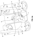
- Fig. 4a shows a second plate (14) is located a predetermined distance away from the first plate (7).
- the second plate (14) is substantially vertically aligned with the first plate (7).
- the predetermined distance between the second plate (14) and the first plate (7) defines the height of the frame structure into which a specific size cylinder (11) can be mounted.
- the second plate (14) has a peripheral region (58) that serves as a support platform for connection of elongated rods (9a, 9b, 9c and 9d).
- Fig. 4a shows a second clamp (28) that is connected to the second plate (14) along a central region (46) of the second plate (14).
- the central region (46) is recessed and centrally located relative to a peripheral region (58) of second plate (14).
- the second clamp (28) in the closed position ( Fig. 4a ) fully encloses and secures the second end of neck of cylinder (11) into the assembly (1').
- the second clamp (28) has two components which include a first portion (31) and a second portion (32) that is separate and distinct from the first portion (31).
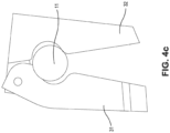
- the first portion (31) is movable into a first open position ( Figs. 4b and 4c ) for mounting the second end of cylinder (11).
- the first portion (31) is also moveable into a second open position ( Figs. 4d, 4e and 4f ) for rotating the second end of cylinder (11) in a secured manner, as may be required for visual inspection.
- the second open position is smaller than the first open position.
- the second portion (32) of second clamp (38) as shown in Fig. 4a remains stationary and is connected (e.g., by using a mechanical connection means such as bolts 78) to the second plate (14).
- the closed position of second clamp (28) fully encloses and locks a recessed region 47 of neck of cylinder (11) along its second end (as will be explained with regards to Figs. 5a and 5b ).
- the first portion (31) of the second clamp (28) is attached to the second portion (32) with a pin-like structure (38), which creates a point of attachment for the first portion (31) of second clamp (28) to pivot relative to the second portion (32).
- First portion (31) pivots between a first open position ( Figs.4b and 4c ), a second open position ( Figs. 4d, 4e and 4f ) and a closed position ( Fig. 4a ).
- a latch (17) is utilized to be able to pivot the first portion (31).
- the latch (17) includes a latch arm (75); a latch keeper (76); and a latch handle (77).
- the latch arm (75) and the latch handle (77) are connected to the edge of first portion (31).
- the latch keeper (76) is connected to the edge of second portion (32).
- the latch arms (75) are fully engaged into the latch keeper (76) as shown in Fig. 4g causing the internal opening of second clamp (28) to be fully enclosed.
- Handle (77) extends outward in close proximity towards the edge of the second plate (14) to allow access by an end-user ( Fig. 1 ).
- the handle (77) can be grasped by an end-user.
- the handle (77) can be outwardly pulled in the manner shown in Figs. 4d, 4e and 4f to cause the first portion (31) to pivot away from the second portion (32) to create the second open position ( Figs. 4d, 4e and 4f ), which represents an opening that allows the second end of cylinder (11) to rotate within the second open position while still remaining in a substantially upright position.
- a restrictor (24) limits the amount that the second clamp (28) can open and remains on second clamp (28) during operational use.
- Figs. 4d, 4e and 4f show the second clamp (28) opened by the same amount (i.e., configured into the second open position), even though the handle (77) has been pulled outwardly by differing amounts.
- a ring-like polymeric material (60) can be inserted within second clamp (28).
- the ring-like polymeric material (60) is shown in Fig. 4a .
- the reduction in friction facilitates rotation by user.
- the ring-like polymeric material (60) includes two washers that are inserted into a recessed section in the second clamp (28) as shown in Fig. 4a .
- One of the washers is preferably made of Delrin ® and the other washer is preferably made from Nylon ® .
- Other materials suitable for reducing friction can be employed.
- the restrictor (24) is removed as shown in Figs. 4b and 4c when mounting a cylinder (11) into the opening of second clamp (28) or removing the cylinder (11) from the opening of second clamp (28). With the removal of restrictor (24), latch handle (77) can be pulled outwardly in the manner shown in Fig. 4b to cause the first portion (31) to pivot away from the second portion (32) a greater amount than shown in Figs. 4d, 4e and 4f to create the required first open position, which is larger than the second open position.
- first portion (31) of second clamp (28) By eliminating nuts and bolts as typically required to fasten first portion (31) of second clamp (28) onto second plate (14), substantial user time and effort is avoided.
- Conventional clamping mechanisms require loosening the first portion (31) of second clamp (28) from the second plate (14) to mount and dismount the cylinder (11).
- the present invention avoids the need to loosen the first portion (31) of second clamp (28).
- the latch mechanism of the present invention can relatively quickly and with ease re-orient the second clamp (28) into the precise and desired opening for mounting or dismounting a cylinder (11) or rotating the cylinder (11).
- the second clamp (28) has a protruded section (48) along each of the inner surfaces of the first portion (31) and second portion (32), respectively, that is designed to mate and fit with a complimentary recessed region 47 ( Fig. 5a ) of the second neck of cylinder 11 and create a so-called "lock and key” mechanism as shown in the cross-sectional view of Fig. 5b. Fig.
- 5c shows the recessed region 47 in the neck of cylinder 11, which is designed and fabricated to fit into the corresponding protruded section (48) along inner surfaces of the second clamp (28) without requiring sole reliance on the so-called "squeeze force" of the second clamp (28) on the neck of cylinder 11 at its second end.
- the inventors have discovered that the combination of a squeeze force with the lock and key mechanism created from protruded section (48) provides a mechanical advantage that allows the cylinder (11) to be sufficiently locked into second clamp (28) with the use of the latch mechanism of the present invention.
- the present invention recognizes that the absence of protruded section (48) from the latch mechanism fails to create a sufficient clamping force for securing second end of cylinder (11).
- One of the unique benefits of the present invention is that the configuration of the first end of cylinder (11) and the second end of cylinder (11) mounted within the support assembly (1') allows the cylinder (11) to rotate for visual inspection while still being maintained substantially upright.
- the method for allowing the rotation will now be described.
- One of the requirements necessary for rotation of the cylinder (11) is to configure the second clamp (28) from the closed position of Figs. 4a and 4g , into the second open position of Figs. 4d, 4e and 4f to create sufficient clearance for recessed region (47) of neck of cylinder 11 to rotate therewithin.
- latch (17) is pulled by a user, and first portion (31) pivots away from second portion (32) to create the second open position shown.
- the restrictor (24) operably connects the first portion (31) to the second portion (32) of second clamp (28), thereby ensuring that an end-user cannot inadvertently pull latch 17 to open the second clamp (28) beyond second open position ( Fig. 4d ) into the first open position ( Figs. 4b and 4c ), which can cause cylinder (11) to tilt and/or fall out of assembly (1').
- the retractable, spring-loaded plunger (16) at the first end can be pulled by a user.
- a user can pull the plunger (16) until the tip-most portion of plunger (16) has been pulled away from notch.
- the plunger (16) when retracted away from notch (43) can be rotated 90 degrees and then placed onto the edge of a ledge-like structure (44) of first clamp (15) and remain rested on the ledge-like structure (44) until a user is ready to release it back into the notch (43).
- the cylinder (11) With the plunger (16) retracted in this manner, the cylinder (11) by virtue of not being attached to the first plate (7) or the secondary structure of first plate (41) is able to rotate within opening of the first plate (7) at the first end while still remaining securely mounted within the opening of first plate (7).
- the ring-like polymeric material 42 between the first end of cylinder (11) and first plate (7) along the top section of assembly (1') provides sufficient stability and support which prevents the cylinder (11) from undesirably tilting at its first end during the rotational movement.
- the cylinder (11) is ready to be rotated freely by a user at its first and second ends, while maintaining secured in the assembly (1').
- the user can apply a torque to the walls and rotate the cylinder (11) without risk of the-recessed region (47) of the neck of the cylinder (11) tilting or falling out of its substantially upright position within the second clamp (28) as a direct result of the novel clamping mechanism of the present invention.
- the tilting or falling out of cylinder (11) is a potentially dangerous condition that can prevent second clamp (28) from properly closing around the recessed region (47) of neck of second end of cylinder (11).
- both ends of the cylinder (11) are re-engaged to the first end and second end of assembly.
- User pushes handle (77) such that latch arm (75) reengages into corresponding slots of latch keeper (76) ( Figs. 4a and 4g ) to secure recessed region (47) of second end of cylinder (11) into second clamp (28).
- User further releases plunger (16) from ledge (44) so that plunger (16) reseats into notch (43) along the side of first clamp(15) ( Figs. 2c and 2d).
- Fig. 2b shows that plunger (16) can be threaded into ledge-like structure (44) when plunger (16) is seated in notch (43).
- the first clamp (15) is specifically positioned such that the notch (43) along the side of the first clamp (15) causes plunger (16) to always reseat in a cylinder orientation where the user port and fill port of valve (13) is positioned as shown in Fig. 1 .
- the user port (79) on the valve (13) faces the opening in the protective ring (8) towards the first side (35) to allow a user to readily access the valve (13) without interference from pillars of protective ring (8), thereby allowing, for example, connection to a regulator onto the user port (79) for dispensing gas product from interior of cylinder (11).
- the fill port (80) is oriented to allow user access without interference from pillars of protective ring (8) (e.g., the fill port (80) is oriented towards third side (69) between pillars of ring (8)). If the plunger (16) were to re-engage in a position where fill port and/or user port is obstructed, the user may encounter difficulties with installation of the regulator onto the valve (13) as required to dispense the product. Accordingly, the selectivity involved with locking the first end of cylinder (11) in a specific orientation that does not obstruct access and use of the user port (79) and fill port (80) is a unique design attribute taken into account by the present invention.
- the order of the steps for allowing rotation of cylinder (11) as well as locking cylinder (11) into assembly (11 ') can be varied.
- the plunger (16) may be retracted from notch (43) of first clamp (15) before pulling latch (17) and configuring second clamp (28) into the second open position.
- the first end of cylinder (11) may be secured with release and reseat of plunger (16) into notch (43) prior to configuring the second clamp (28) into the closed position.
- a protective ring (8) is shown attached to the first plate (7).
- the protective ring (8) partially encapsulates a valve (13) of the cylinder (11), which serves, at least in part, to protect the valve (13) from rupture or other damage in the event the cylinder (11) or a top portion thereof, when mounted into the transportable support assembly (1'), falls onto another surface.
- the protective ring (8) is designed to absorb at least a portion of the impact of such a fall, thereby preventing damage to the valve (13).
- the assembly (1') is capable of protecting the valve (13) upon such drops such that insubstantial displacement of the first end of neck of cylinder 11 along the top thereof is observed.
- the protective ring (8) is designed to have a substantially u-shaped bend with an opening extending towards the first side 35 of assembly (1') towards the user side.
- the opening in the protective ring (8) allows a user to access the valve (13).
- the Figures show that the u-shaped bend is situated along the first plate (7) and extends approximately 270° around the valve (13).
- the wheels as shown in Figure 1 are operably connected to the second plate (14) along a peripheral region (58) of the second plate (14).
- a first wheel (1a) and a second wheel (1b) are provided along a first side (35) of the assembly (1').
- the first wheel (1a) and the second wheel (1b) are spaced apart from each other by a predetermined distance that is sufficient to minimize tipping of the assembly (1 ').
- the first wheel (1a) and the second wheel (1b) are non-rotatable.
- the assembly (1') also includes a third wheel (2a) and a fourth wheel (2b) along a second side (36) of the assembly (1'), where the second side (36) preferably and as shown in Figure 1 is diametrically opposed to the first side (35).
- the third wheel (2a) and the fourth wheel (2b) are spaced apart from each other by a predetermined distance that is sufficient to minimize tipping of the assembly (1').
- the third wheel (2a) and the fourth wheel (2b) are spaced apart by the same distance as that of the first wheel (1a) and the second wheel (1b).
- the third wheel (2a) and the fourth wheel (2b) are preferably rotatable while the first wheel (1a) and the second wheel (1b) are non-rotatable.
- Such a combination allows a user to tip the assembly (1') with stability and increased maneuverability.
- the present invention recognizes that if the user is holding the handle (3) and tipping the cylinder (3), the cylinder (3) can actually start to move or at minimum exhibit a tendency to move if the first wheel (1a) and second wheel (1b) can rotate.
- the preferred design employs a first wheel (1a) and second wheel (1b), both of which are non-rotatable.
- a foot ledge (12) is shown in Fig. 1 secured to the second plate (14) along the first side (35).
- the foot ledge (12) is located below the second plate (14) and extends towards ground level.
- the foot ledge (12) is located between the first wheel (1a) and the second wheel (1b).
- the user can grab handle (3) along first side (35) and place a foot on foot ledge (12) located at second end of second plate (14) and tip the assembly (1) along first wheel (1a) and second wheel (1b) towards user in a stable manner as a result of the first wheel (1a) and second wheel (1b) remaining non-rotatable.
- Such tipping of assembly (1') with use of the foot ledge (12) is advantageous when maneuvering and transporting the assembly (1) over a ridge or other type of surface irregularity on the ground which can create an uneven surface.
- any diameter for the wheels (1a, 1b, 2a and 2b) are contemplated. Preferably all wheels (1a, 1b, 2a and 2b) are the same diameter. However, the first wheels (1a and 1b) may be a different diameter than the second wheels (2a and 2b).
- the assembly (1') also includes a handle (3) along the first side (35).
- the handle (3) has a horizontal portion extending between a first elongated rod (9a) and a second elongated rod (9b). Each end of such horizontal portion extends downwards a sufficient amount and then attaches to the first elongated rod (9a) and the second elongated rod (9b).
- the vertical portions of handle (3) span a sufficient range to allow a range of users of differing height levels to grasp along the vertical portions with relative ease to hold, move and maneuver the assembly (1').
- a braking mechanism is utilized to increase safety when transporting assembly (1') with cylinder (11).
- the assembly (1') utilizes a dead man braking mechanism.
- the dead man braking mechanism maintains the brakes on the wheels at all times, until a user chooses to squeeze the dead man actuator towards handle (3).
- the deactivated state means the brakes are applied onto the wheels and the activated state means the brakes are not applied onto the wheels.
- Such a braking mechanism eliminates the risk of a user transporting an unsecured cylinder (11) within frame structure of assembly (1').
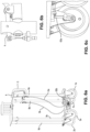
- Fig. 1 and Fig. 6a show a dead man brake actuator (4) that extends along a portion of the handle (3).
- one end of the actuator (4) is connected to a first brake cable (5a); and another end of the actuator (4) is connected to a second brake cable (5b).
- Brake cable (5a) is connected to spring loaded lever (63a), and brake cable (5b) is connected to spring loaded lever (63b).
- a drum brake system as shown in Figs. 7a and 7b .
- brake shoe (64a, 64b) means a first brake shoe (64a) for first wheel (1a) and a second brake shoe (64b) for second wheel (1b); and brake shoe (65a, 65b) means a second brake shoe (65a) for first wheel (1a), and a second brake shoe (65b) for second wheel.
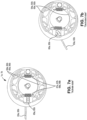
- Figs. 7a and 7b show the details of the drum brake system utilized by first wheel (1a) and second wheel (1b).
- the drum brake system is made up of two brake shoes (64a, 64b) and (65a, 65b) on each side of the inside of first wheel (1a) and second wheel (1b).
- Brake shoe (64a, 64b) is connected to brake shoe (65a, 65b) by a set of springs (67a, 67b) and (68a, 68b), where springs 67a and 68a refer to the springs in first wheel (1a); and springs 67b and 68b refer to the springs in second wheel (1b).
- An elliptical-shaped cam (66a, 66b) as shown in Figs. 7a and 7b is located between the two brake shoes (64a, 64b) and (65a, 65b), and a cylinder-shaped drum.
- the cylindrical-shaped drum extends around the brake shoes (64a, 64b) and (65a, 65b). In the Figures of 7a and 7b, the cylindrical-shaped drum is omitted for purposes of better illustrating the principles of the dead man brake mechanism with clarity.
- the cam (65a, 65b) is connected to the spring-loaded lever (63a, 63b).
- the spring force applied to the lever (63a) for first wheel (1a) and the spring force applied to the lever (63b) for second wheel (1b) positions the corresponding cam (65a, 65b) for corresponding first wheel (1a) and second wheel (1b) such that the length of the respective cam (65a, 65b) creates separation between the two brake shoes 64a and 65a of first wheel (1a) and brake shoes 64b and 65b of second wheel (1b).
- Fig. 7b shows the resultant configuration of the cam (65a, 65b), brake shoes (64a, 64b) and (65a, 65b) and lever (63a, 63b) in the deactivate state in which the drum prevents rotation of the wheels (1a, 1b).
- the dead man brake may readily be modified to be used on all of the wheels (first wheel (1a), second wheel (1b), third wheel (2a) and fourth wheel (2b)).
- the present invention may also include other brake designs.
- the brake design may include caster locks on any or all of the wheels.
- disc brakes or bicycle brakes may be employed.
- the assembly (1') can secure and transport cylinders, without a reduction in stability (e.g., no increased tendency for falling) and/or without a reduction in maneuverability (e.g., no increased safety risk associated with tilting the cylinder).
- Various sized cylinders can be secured to the assembly (1').
- a T size cylinder can be employed, having a diameter of about 23.5 cm (9.25 inches) and a height of about 130 cm (51 inches).
- two or more T cylinders can be banded together to form a bundle.
- a customized cylinder with a height of up to 213 cm (7 ft) and a diameter of between 17.8 and 102 cm (7 and 40 inches) can be secured into the frame (1').
- cylinders with greater heights and weight have been more difficult to navigate, maneuver and tip for purposes of transporting over an elevated surface or other uneven surface.
- the structural attributes of the inventive assembly (1') allow for improved maneuverability and transport of relatively large cylinders (e.g., T sized cylinders) in a stable manner.
- the novel design reduces the tendency of tipping for even large and heavy T sized cylinders.
- the assembly (1') has been engineered to maintain structural integrity of the valve (13) under repeated high impact drops or free falls of the assembly (1') to the ground.
- the transportable support assembly (1') may include a modular housing.
- the modular housing can facilitate relatively quick assembly of on-board components and enable visual inspection of the cylinder (11).
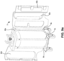
- Figures 8a-8c and Figures 9a-9b show a modular housing 71designed to close and open for visually inspecting the cylinder (11) which is mounted and secured onto the transport support assembly (1').
- the modular housing 71 includes a panel enclosure (82) which wraps around the multiple elongated rods (9a, 9b, 9c and 9d).
- Fig. 9 shows that only one section of the panel enclosure 82 is connected to the multiple elongated rods (9a, 9b, 9c and 9d).
- Figure 9 shows the modular housing 71 opened.
- the modular housing 71 can be characterized as having four panel sections, namely, a first section 82a, a second section, 82b, a third section 82c and a fourth section 82d.
- a first section (82a) remains permanently closed and secured along a first side (35) which is bounded by elongated rods (9a) and (9b);
- a second section (82b) closes and opens along a second side (36) diametrically opposed to first side (35) where the second side (36) is bounded by elongated 9c and 9d;
- a third section (82c) closes and opens along a third side (69) of assembly (1') which is bounded by elongated rods (9a) and (9c);
- a fourth section (82d) closes and opens along a fourth side (70) diametrically opposed to third side (69) and where the fourth side (70) is bounded by elongated rods (9b) and (9d).
- each of the panel sections (82a, 82b, 82c and 82d) can be varying sizes.
- Figure 9 shows that a first section of the panel enclosure (82a) is only connected along the first side (35).
- Brackets (74) as shown in Figs. 8b and 8c or other suitable elements may be welded at specific locations on elongated rods (9a) and (9b) to secure the panel enclosure (82) along the first side (35).
- Various structural elements can be fastened onto the panel enclosure (82a) to engage with brackets (74) of the elongated rods (9a) and (9b) along first side (35) of assembly (1'), including but not limited to nuts and bolts; jack nuts; and thread forming screws.
- the remaining sections (82b), (82c) and (82d) of the panel enclosure (82) can open and close as shown in Figure 9 to allow visual inspection of the cylinder (11), which can be configured to rotate as previously described herein.
- Section 82b can latch and unlatch onto the corresponding section (82d) of panel enclosure (82) to allow opening and closing.
- a hinge is preferably present between section (82d) and (82a) of plastic enclosure (82) and also between section (82a) and (82c) of plastic enclosure (82).
- a hinge may also be present between panel section (82b) and panel section (82d).
- panel sections (82b) and (82d) may be secured together permanently using any suitable means, such as metal fasteners.
- Typical metal fasteners include threaded inserts and '82b configured in substantial alignment, thereby fully exposing a second side (36), a third side (69) and a fourth side (70) of assembly (1').
- the cylinder(11) can be visually inspected and rotated by a user pulling latch (17) into the second open position ( Fig. 4d ), as described hereinbefore.
- a top plastic housing 72 may also be secured to the top plate (7) by any suitable means, including, but not limited to, thread forming screws 81, as shown in Figs. 10b and 10b .
- the modular housing (71) is one example and other enclosures may be utilized for transport assembly (1').
- a so-called "boot” may be configured to receive a bottom section of the cylinder.
- a permanently enclosed housing may be employed if visual inspection of the cylinder (11) is not required.
- Other housing structures may only partially cover the assembly or be made out of other materials such as metal.
- Various means for fabricating the frame of the transport assembly (1') are contemplated.
- One example involves cutting and bending the first plate (7) and second plate (14) to the requisite shape and dimensions.
- the elongated rods (9a), (9b), (9c) and (9d) are cut to the required lengths and then each elongated rod (9a), (9b), (9c) and (9d) is welded to the second plate (14) at a specific location of second pate (14) along its periphery (58).
- the protective ring (8) can be fabricated as a separate component whereby solid rods are cut and bent to a specific radius of curvature to achieve the u-shaped bend geometry.
- the resultant u-shape protective ring (8) can then be welded to the first plate (7).
- Vertical posts are preferably welded to each of the four corners below the first plate (7).
- This first plate-protective ring sub-assembly is then positioned over the elongated rods (9a), (9b), (9c) and (9d) and then fastened with cotter pins.
- any suitable means for connecting the sub-assembly to the elongated rods (9a), (9b), (9c) and (9d) can be utilized without departing from the scope of the invention.
- any suitable material may be used to form modular housing (67).
- the panel sections 82a-82d are a single blow molded plastic material, such as high density polyethylene; and the top housing is an suitable plastic material.
- the panel sections are molded as separate components which are then attached to each other by any suitable means.
- a first drop test was conducted according to standard ISO11117:1998(E) to evaluate the structural integrity of the assembly (1') and its ability to protect the integrity of a cylinder valve (13) when secured on the assembly (1').
- Substantially steel-based components were fabricated by the inventors to create the transport support assembly (1') as shown in Figure 1 .
- a composite cylinder (height of 118 cm (46.5 inches) and diameter of 51 cm (20 inches)) was mounted and secured onto the second plate (14).
- the neck portion at the second end of the cylinder (11) had a recessed region (47) which was mated and fitted within a complimentary protruded section (48) within the opening of second clamp (28).
- the first end of cylinder (11) at the top of the assembly (1') was mounted so that it extended through the inner opening of the first clamp (15), which was located below a first plate (7).
- the first clamp (15) was not connected to the first plate (7).
- a Delrin ® washer (42) extended through the first clamp (7) and onto the first plate (7), as shown in Figures 2c and 3b , contacted the outer surface of the first neck of cylinder (11) and thereby provided the necessary support and maintenance of the cylinder (11) along the first end in a substantially upright position.
- the assembly (1') with cylinder (11) was elevated in an inverted orientation so that the top protective ring (8) was closest to the ground.
- the assembly (1) with cylinder (11) was raised until the top protective ring (8) was 1.83 m (6 feet) from the ground (i.e., impact surface).
- a fixture was built to properly hold the cylinder (11) with the longitudinal axis of the cylinder (11) at an angle of 30° to the vertical.
- the first drop test was conducted so that a first point on protective ring (8) was subject to impact upon hitting the ground.
- the fixture was configured so that the first point of ring (8) represented the closest point of ring (8) to the ground. In this manner, a worse-case scenario was simulated where the stress of the impact is concentrated.
- the fixture Suspended in this starting position, the fixture released the assembly (1') with cylinder (11), causing it to drop onto an unyielding surface at the first point of the protective ring (8).
- the valve (13) did not incur visible damage that would be expected to cause leakage of gas from the valve (13) itself. Additionally, the connection between the valve (13) and the cylinder (11) remained capable of opening and closing.
- the valve (13) was defined as operable and the first drop test was deemed successful in accordance with ISO 11117:1998(E).
- Example 2 Utilizing the same apparatus (1') and cylinder (11) of Example 1, a second drop test was conducted in a manner identical to Example 1. The second drop test was conducted so that a second point of protective ring (8) spaced apart 60°from the first point of ring (80) was subject to impact when hitting the ground. To ensure the second point of ring (8) was subject to impact, the fixture rotated assembly (1') on its axis 60° relative to that of Example 1 so that the second point of ring (8) represented the closest point of ring (8) to the ground. The valve (13) did not incur visible damage that would be expected to cause leakage of gas from the valve (13) itself. Additionally, the connection between the valve (13) and the cylinder (11) remained capable of opening and closing. The valve (13) was defined as operable and the second drop test was deemed successful in accordance ISO 11117:1998(E).
- Example 2 Utilizing the same apparatus (1') and cylinder (11) of Example 1, a third drop test was conducted in a manner identical to Examples 1 and 2. The third drop test was conducted so that a third point of protective ring (8) spaced apart 60° from the second point of protective ring (80) was subject to impact when hitting the ground. To ensure the third point of ring (8) was subject to impact, the fixture rotated assembly (1') on its axis 60° relative to that of Example 2, so that the third point of ring (8) represented the closest point of protective ring (8) to the ground.
- valve (13) did not incur visible damage that would be expected to cause leakage of gas from the valve (13) itself. Additionally, the connection between the valve (13) and the cylinder (11) remained capable of opening and closing. The valve (13) was defined as operable and the third drop test was deemed successful in accordance ISO 11117:1998(E).
- Example 1 Utilizing the same apparatus (1') and cylinder (11) of Example 1, a fourth drop test was conducted in a manner identical to Examples 1, 2 and 3. The fourth drop test was conducted so that a fourth point of protective ring (8) spaced apart 60° from the third point of protective ring (80) was subject to impact when hitting the ground. To ensure the fourth point of ring (8) was subject to impact, the fixture rotated assembly (1') on its axis 60° relative to that of Example 3, so that the fourth point of ring (8) represented the closest point of protective ring (8) to the ground. The valve (13) did not incur visible damage that would be expected to cause leakage of gas from the valve (13) itself. Additionally, the connection between the valve (13) and the cylinder (11) remained capable of opening and closing. The valve (13) was defined as operable and the fourth drop test was deemed successful in accordance with ISO 11117:1998(E).
- a fifth drop test was conducted in a manner identical to Examples 1, 2, 3 and 4.
- the fifth drop test was conducted so that a fifth point of protective ring (8) spaced apart 60° from the fourth point of protective ring (80) was subject to impact when hitting the ground.
- the fixture rotated assembly (1') on its axis 60° relative to that of Example 4, so that the fifth point of ring (8) represented the closest point of protective ring (8) to the ground.
- the valve (13) did not incur visible damage that would be expected to cause leakage of gas from the valve (13) itself. Additionally, the connection between the valve (13) and the cylinder (11) remained capable of opening and closing.
- the valve (13) was defined as operable and the fifth drop test was deemed successful in accordance to ISO 11117:1998(E).
- Example 1 Utilizing the same apparatus (1') and cylinder (11) of Example 1, a sixth drop test was conducted in a manner identical to Examples 1, 2, 3, 4 and 5. The sixth drop test was conducted so that a sixth point of protective ring (8) spaced apart 60° from the fifth point of protective ring (80) was subject to impact when hitting the ground. To ensure the sixth point of ring (8) was subject to impact, the fixture rotated assembly (1') on its axis 60° relative to that of Example 5, so that the sixth point of ring (8) represented the closest point of protective ring (8) to the ground. The valve (13) did not incur visible damage that would be expected to cause leakage of gas from the valve (13) itself. Additionally, the connection between the valve (13) and the cylinder (11) remained capable of opening and closing. The valve (13) was defined as operable and the sixth drop test was deemed successful in accordance to ISO 11117:1998(E).
- the present invention offers numerous benefits over conventional carts.
- the ability of the present invention (i) to maintain structural integrity of the valve (13) in a worst-case scenario; (ii) securely lock cylinder (11) with a quick-release, user-friendly latch mechanism; (iii) allow the cylinder (11) to rotate while remaining substantially upright; (iv) prevent inadvertent rolling or movement with a dead man brake mechanism; (v) allow selective tipping and rotated wheels for improved maneuverability and stability during transport are improvements not realized or possible by conventional mobile apparatuses.
- the benefits of the present invention become even more significant with larger capacity cylinders or containers mounted on assembly (1').
- the ability to use heavier and larger T-sized cylinders on carts that offered all of the benefits of the present invention was not possible prior to emergence of the present invention; such larger sized cylinders reduce the frequency of loading and unloading of cylinders on carts.
- the present invention allows an empty cylinder to remain mounted on assembly (1') and be filled in a safe, fast and reliable manner.
- a cylinder weighing greater than 150 kg may likely pose significant risk if utilized on a conventional cart and be generally ineffective for transport and maneuver over uneven surfaces.
- the assembly (1') can be equipped with sensors to measure the amount of content stored inside the cylinder (11). For example, if the cylinder (11) stores a compressed gas, the pressure of the compressed gas stored inside the cylinder (11) can be measured to determine the amount of gas content.
- the assembly (1') can also be equipped with other sensors to manage, monitor, measure and/or store various attributes, including, but not limited to, operational data, such as temperature of the stored gas in the cylinder (11), and flow rate of the gas withdrawn from the cylinder (11) during usage.
- the sensors are preferably configured to transmit the measured operational data wirelessly to a remote data storage unit.
- the measured operational data from the remote data storage unit can be retrieved in any manner, such as, for example, at regular intervals or real-time to manage, monitor, measure and/or store the operational data.
- the data can be inputted into a control system to configure alarms to allow corrective action to be manually or automatically implemented when one or more selected attributes have been determined to reach a pre-defined set-point. For example, a user may decide to replace a depleted assembly (1') with a replenished assembly (1') having a cylinder (11) with more gas content when the pressure of gas inside the cylinder (11) of the depleted assembly (1') drops below a certain limit. In another example the user may decide to isolate the cylinder (11) from a flow manifold when the flow rate is more than a desired set point.
- the operational data from a single assembly (1') or in combination with several other assemblies (1') deployed at the same physical location or at different physical locations can also be used to generate predictive analytics around the usage of the content from the cylinder (11) and forecast future usage rates.
- the protective ring (8) may include more or less than five vertical bars.
- the protective ring (8) can include three or four vertical bars extending between the first plate (7) and the u-shape bend structure, with one or more of the vertical bars located at positions along the u-shape bend structure that are different than shown in the Figures.
- the size and shape of the u-shape bend may be modified as well.
- a u-shaped or c-shaped bend may be configured to have a larger radius of curvature.
- the protective ring (8) may attach to a first plate (7) without reinforcement sheet attached (e.g., welded) underneath the first plate (7).
Landscapes
- Engineering & Computer Science (AREA)
- Chemical & Material Sciences (AREA)
- Mechanical Engineering (AREA)
- Combustion & Propulsion (AREA)
- Transportation (AREA)
- General Engineering & Computer Science (AREA)
- General Chemical & Material Sciences (AREA)
- Chemical Kinetics & Catalysis (AREA)
- Materials Engineering (AREA)
- Metallurgy (AREA)
- Organic Chemistry (AREA)
- Filling Or Discharging Of Gas Storage Vessels (AREA)
- Supplying Of Containers To The Packaging Station (AREA)
Description
- The present invention relates to improved support assemblies for holding a container capable of transporting and maneuvering the container with stability.
- Typically, compressed gases are delivered as a pressurized vessel to a customer site. Such pressurized vessels are fitted with a dispensing valve and are commonly referred to as "gas cylinders". The movement of gas cylinders throughout various regions of onsite premises is often required by an end-user. However, transporting and maneuvering such gas cylinders from one point to another can be a difficult task, especially when the distances to be travelled are along narrow and/or constricted pathways, some of which may have uneven or elevated surfaces. The operational challenge can be exacerbated when the gas cylinders to be maneuvered increase in weight (e.g., up to about 150 kg), as the increase in weight can increase the tendency for the gas cylinders to fall while moving the cylinder. Handling of the gas cylinders becomes problematic, and the risk of safety hazards can potentially increase.
- One known solution to remedy such operational challenges involves loading the gas cylinders onto a cart with wheels. However, such a solution still has numerous drawbacks. For example, the loading and unloading of the gas cylinders from the cart, even if only for relatively small distances within an on-site premise, still poses operational challenges and safety hazards. The problem is further compounded when the usage rate of these gas cylinders are increased, thereby requiring the end-user to accommodate the handling of a larger quantity of gas cylinders, and/or increase the storage capacity of the gas cylinders to avoid a substantial increase in the numbers of cylinders to be handled.
-
US 2011/318149 A1 relates to a transportable support assembly for gas cylinder according to the preamble ofclaim 1.CN 107351895 A andDE 20 2015 102 466 U1 relate to gas cylinder transport vehicles comprising a protective ring around the gas cylinder.US 2005/194218 A1 relates to a shopping cart with a dead man brake for the wheels. - There is currently no viable mobile apparatus to store and transport pressurized vessels in a way that mitigates the foregoing operational challenges and safety hazards. There remains an unmet need for an improved mobile storage and transport apparatus that allows maneuverability of gas cylinders in a safe and user-friendly manner. Other aspects of the present invention will become apparent to one of ordinary skill in the art upon review of the specification, drawings and claims appended hereto.
- The invention relates to a transportable support assembly as defined in
claim 1, discovered to provide improved maneuverability, safety and protection of containers mounted and secured to the transportable support assembly. Preferred embodiments are defined in the dependent claims. - The objectives and advantages of the invention will be better understood from the following detailed description of the preferred embodiments thereof in connection with the accompanying figures wherein like numbers denote same features throughout and wherein:
-
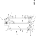
Figure 1 shows an overall schematic of an exemplary transport support assembly with wheels, handle and a braking mechanism and a cylinder securely mounted within the frame assembly of the transport support assembly, in accordance with the principles of the present invention; -
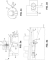
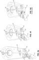
Figures 2a, 2b, 2c and 2d show, among other structural features, an enlarged view of the arrangement of the cylinder and the first clamp and first plate at the first end at the top of the assembly, in accordance with the principles of the present invention; -
Figures 3a, 3b and 3c show an enlarged view of the arrangement of the first plate and the first end of cylinder at the top of the assembly, in accordance with the principles of the present invention; -
Figure 4a shows a second plate with second clamp in the closed position; -
Figure 4b shows an enlarged view of the latch fully disengaged from the keeper and with restrictor removed from top of second clamp to allow the second clamp to be configured into the first open position that is sized to allow cylinder to be mounted therein; -
Figure 4c shows a top view of second clamp ofFigure 4b ; -
Figures 4d, 4e and 4f show the second clamp in the second open position sized to allow a cylinder to be rotated therein; -
Fig. 4g shows the latch arms of latch fully engaged into the latch keeper to cause the second clamp to be in the closed position; -
Figure 5a shows the neck of cylinder having a recessed region which is designed to mate and fit within a complimentary protruded section of second clamp at the second end of the assembly; -
Figure 5b shows a cross section of the neck of cylinder having a recessed region engaged with the protruded section of second clamp at the second end of the assembly; -
Figure 5c shows the protruding section of second clamp along the inner surfaces of the first portion and the second portion of the second clamp; -
Figures 6a, 6b, 6c show the outer components of the dead man brake mechanism; -
Figure 7a and 7b show the inner components of the braking mechanism within a wheel; -
Figures 8a, 8b and 8c show a modular panel housing entirely enclosed around the assembly; -
Figure 9 shows the modular panel enclosure ofFigure 8a in the fully open configuration for visual inspection of the cylinder mounted and secured in the assembly; and -
Figures 10a and 10b show a top housing enclosed over top plate. - The relationship and functioning of the various elements of this invention are better understood by the following detailed description.
- In the drawings, like numerals indicate like elements throughout. Certain terminology is used herein for convenience only and is not to be taken as a limitation on the present invention.
- As used and throughout, the term "container" is intended to mean any type of storage, filling and/or dispensing vessel which is a cylinders which is suitable for filling, storing, transporting, and/or delivering materials, including gases and liquefied gases.
- The terms "operably connected" and "connected" may be used interchangeably herein and throughout and are intended to mean a direct or indirect connection between two or more components by way of mechanical, chemical and/or electrical communication between the two or more components.
- As used herein and throughout, unless indicated otherwise, all concentrations are expressed as volumetric percentages ("vol%").
- As used herein and throughout, "about" or "approximately" when referring to a measurable value such as an amount is meant to encompass variations of ±20%, ±10%, ±5%, ±1% and ±0.1% from the specified value, as such variations are appropriate.
- Throughout this disclosure, various aspects of the invention can be presented in range format. It should be understood that the description in range format is merely for convenience and brevity and should not be considered as a limitation on the scope of the invention. Accordingly, the description of a range should be considered to have specifically disclosed all the possible subranges as well as individual numerical values within that range. For example, description of a range such as from 1 to 6 should be considered to have specifically disclosed subranges such as from 1 to 3, from 1 to 4, from 1 to 5, from 2 to 4, from 2 to 6, from 3 to 6 etc., as well as individual numbers within that range, for example, 1, 2, 2.7, 3, 4, 5, 5.3, 6 and any whole and partial increments therebetween. This applies regardless of the breadth of the range.
- It should be noted, by way of example, and in connection with the Figures, a "first end" refers to a top of the assembly (1') and a "second end" refers to a bottom of the assembly (1'). However, it should be understood that various design variations are contemplated such that the "first end" may refer to a bottom of assembly (1') and "second end" may refer to a top of the assembly (1'); or the "first end" and the "second end" may each represent another end of the assembly (1') relative to each other.
- It should be also noted that, by way of example, and in connection with the Figures, a "first side" of the assembly (1') represents a user-side, which is a location where a user can hold the handle (3) to maneuver and transport the assembly (1'); and a "second side" represents a rear side of the assembly(1') which is substantially diametrically opposed to the first side (35) of the assembly (1'). However, it should be understood that various design variations are contemplated such that the "first side" may refer to the rear side of assembly (1') and "second side" may refer to a user side of the assembly (1;); or the "first side" and the "second side" may each represent a different side or region of the assembly (1') relative to each other.
- A "third side" and "fourth side" are intended to be regions extending between the "first side" and "second side".
- In view of the lack of a suitable mobile storage apparatus, the present invention has emerged. Referring to
Figure 1 , the disclosure in one aspect relates to a transportable support assembly (1') configured to securely hold and move a container (11) on the assembly (1') with improved maneuverability and stability. The container (11) is a cylinder. The transportable support assembly (1') includes a frame structure. The frame structure provides a cage-like enclosure (29) that serves as a protective opening for the cylinder (11). The cage-like structure (29) is formed from multiple elongated rods. In one embodiment, a total of four elongated rods are utilized, namely elongated rods (9a), (9b), (9c) and (9d). The arrangement of each of the elongated rods (9a), (9b), (9c) and (9d) creates an opening that is sized to receive the cylinder (11). Elongated rod (9d) can be seen inFig. 4a . Referring toFig. 1 , elongated rod (9d) is located behind elongated rod (9b) into the plane of the paper, and as a result is not visible. - For purposes of describing the embodiments in connection with the Figures, the first side (35) is bounded by elongated rods(9a) and (9b); the second side (36) is diametrically opposed to the first side (35) where the second side (36) is bounded by elongated rods (9c) and (9d); the third side (69) is bounded by elongated rods (9a) and (9c); and a fourth side (70) is diametrically opposed to third side (69) where the fourth side is bounded by elongated rods (9b) and (9d).
- The multiple elongated rods (9a, 9b, 9c and 9d) extend between a first plate (7) and a second plate (14). In one embodiment, and referring to
Figure 1 , the first plate (7) is located above the second plate (14). The first plate (7) is angled in a downward direction towards the first side 35 (e.g., user side) in an amount sufficient to create clearance for a user to access thevalve 13 of cylinder (11). In particular, referring toFigure 1 , a first end of each of the four elongated rods (9a, 9b, 9c 9d) is operably connected to a corresponding first region along the peripheral region (49) of the first plate (7), and a second end of each of the four elongated rods (9a, 9b, 9c, 9d) is operably connected to a corresponding second region along the peripheral region (58) of the second plate (14). The elongated rods (9a, 9b, 9c, 9d) create a frame structure that is substantially upright, and substantially aligned with the longitudinal axis of the cylinder (11) when mounted and secured therein. In this manner, the vertical alignment of the frame structure of assembly (1') with the cylinder (11) can minimize any tendency for tipping of the assembly (1') and enable the assembly (1') with cylinder (11) mounted and secured therein to be transported and maneuvered with stability by a user. - Any suitable shape, material and wall thickness is contemplated so as to impart the necessary structural integrity to the assembly (1'), which requires passing the requisite drop test in accordance with ISO 111 17:1998(E), as will be explained in greater detail in the Examples. The four elongated rods (9a, 9b, 9c and 9d) preferably are tubular. The tubular structures may be formed from various suitable materials (e.g., stainless steel, carbon steel, or aluminum) with varying suitable inner diameter (e.g., 1.27 - 6.35 cm (0.5 - 2.5 inches)) and varying suitable outer diameter (e.g., 1.27 - 6.35 cm (0.5 - 2.5 inches)) so as to impart the required structural integrity to the assembly (1').
- The arrangement of the cylinder (11), first clamp (15) and first plate (7) at the first end, in accordance with the principles of the present invention, will now be discussed.
Figures 2a, 2b, 2c and 2d show, among other structural features, an enlarged view of the spatial relationship between first plate (7); first clamp (15) with a retractable, spring-loaded plunger (16); and the first end of the cylinder (11). Consistent withFigure 1 , the first end as shown inFigures 2a, 2b, 2c and 2d refers to the top of the assembly (1'), which includes the first neck of cylinder (11), the first plate (7) and the first clamp (15). The first clamp (15) as shown inFigs. 2b and 2c is spaced below the first plate (7) and not attached to the first plate (7), thereby allowing the first clamp (15) to rotate without any restriction or interference from the first plate (7) or the secondary structure (41) of first plate (7). The first end of cylinder (11) extends through the inner opening in the first clamp (15); the inner opening of the secondary structure (41) of the first plate (7); and the opening in the first plate (7). A ring-like polymeric material 42 (e.g., Delrin®, commercially available from DowDupont™) is located within the inner surface of the first plate (7) (Fig. 3b and 3c ).. The ring-like polymeric material (42) extends through opening of first plate (7) and the secondary structure (41) of the first plate (7) and is attached onto the first plate (7) as shown inFigure 3b . The ring-like polymeric material (42) extends around first end of cylinder (11) to support and maintain the cylinder (11) along the first end in a substantially upright position. The outer surface of the first neck of the cylinder (11) contacts the ring-like polymeric material 42 when the cylinder (11) is fitted into the inner opening of first plate (7). - The first clamp (15) as shown in
Fig. 2c engages with a retractable, spring-loaded plunger (16) to maintain its position after having been installed into the correct position around the first end of the neck of cylinder (11). A side of the first clamp (15) is shown abutted to the retractable, spring-loaded plunger (16) in its unbiased state. The plunger (16) is located within a complimentary notch (43) located at a predetermined position along the side of the first clamp (15). In the engaged configuration, the plunger (16) prevents the first clamp (15) and first end of neck cylinder (11) situated within opening of first clamp (15) from rotating. - The retractable, spring-loaded plunger (16) can be pulled by a user when the cylinder (11) needs to be rotated for visual inspection or for other purposes which may arise during use and/or maintenance. A user can pull the plunger (16) away from the first clamp (15) until the tip-most portion of plunger (16) has been pulled away from the edge of notch (43), thereby entirely removing the plunger (16) from notch (43) and allowing the cylinder (11) within the first clamp (15) to rotate with the first clamp (15), so long as the second end of the cylinder (11) is also configured to rotate (the mechanism for which will be discussed below). Referring to
Figure 2d , the plunger (16) when retracted away from notch (43) can be rotated about 90 degrees and placed onto a ledge-like structure (44) (shown inFig. 2d ) of first clamp (15), where the retracted plunger (16) can remain rested in such position out from notch (43).Fig. 2b shows that ledge-like structure (44) is connected to secondary structure (41) of first plate (41). With the plunger (16) retracted, the cylinder (11) and first clamp (15), by virtue of not being attached to the first plate (7) or the secondary structure of first plate (41), is free to rotate with the first clamp (15) while still remaining securely mounted within the opening of first clamp (15) at the first end of assembly (1'). The ring-like polymeric material (42) between the first end of outer surface of neck of cylinder (11) and inner opening of the first plate (7) provides sufficient stability and support which prevents the cylinder (11) from undesirably tilting during rotational movement. - After rotation of the cylinder (11) has been completed, a user can release plunger (16) from its resting position on ledge-like structure (44) so that it reseats into notch (43) as shown in
Fig. 2c . The plunger (16) engagement into notch (43) of first clamp (15) ensures that the cylinder (11) is locked into its unbiased and correct orientation, where the correct orientation, as will be further explained hereinbelow, requires the user port (79) of valve (13) to be facing the first side (35) of assembly (1') such that a user can access user port (79) and fill port (80) of valve (13) through opening of protective ring (8) without obstruction or interference of protective ring (8). -
Figures 3a, 3b and 3c show an enlarged view of the spatial arrangement of the first plate (7) and the first end of cylinder (11) at the top of the assembly (1').Figure 3a shows the first end of cylinder (11) extending through an opening of first plate (7). A gap exists between the first end of cylinder (11) and the opening of first plate (7). The gap provides sufficient clearance for the cylinder (11) to rotate as well as undergo thermal expansion. For purposes of clarity for viewing such gap, the attachment of ring-like polymeric material 42 onto first plate (7) has been omitted fromFig. 3a . -
Figure 3b shows the ring-like polymeric material 42 extending through the gap and attached onto the first plate (7).Figure 3c shows a corresponding cross-sectional view of the first end of cylinder (11) in spatial relation to first plate (7) and secondary structural support of first plate (41) below first plate (7) with ring-like polymeric material 42 extending around the first end of neck of cylinder (11). The ring-like polymeric material 42 is shown located within the inner opening of the first plate (7). For purposes of showing the relative orientation of polymeric material (42) to the first end of cylinder (11), the first plate (7) and secondary structural support of first plate (41) inFig. 3c are shown as a single component. - The secondary structure (41) below the top plate (7) is preferably utilized to absorb at least a portion of the stresses created should the cylinder (11) mounted on assembly (1') tilt or fall.
-
Fig. 4a shows a second plate (14) is located a predetermined distance away from the first plate (7). The second plate (14) is substantially vertically aligned with the first plate (7). The predetermined distance between the second plate (14) and the first plate (7) defines the height of the frame structure into which a specific size cylinder (11) can be mounted. The second plate (14) has a peripheral region (58) that serves as a support platform for connection of elongated rods (9a, 9b, 9c and 9d). - Unlike the first end, the neck of the cylinder (11) at the second end when mounted and secured in assembly (1') is mechanically attached onto a second clamp (28).
Fig. 4a shows a second clamp (28) that is connected to the second plate (14) along a central region (46) of the second plate (14). The central region (46) is recessed and centrally located relative to a peripheral region (58) of second plate (14). The second clamp (28) in the closed position (Fig. 4a ) fully encloses and secures the second end of neck of cylinder (11) into the assembly (1'). - The second clamp (28) has two components which include a first portion (31) and a second portion (32) that is separate and distinct from the first portion (31). The first portion (31) is movable into a first open position (
Figs. 4b and4c ) for mounting the second end of cylinder (11). The first portion (31) is also moveable into a second open position (Figs. 4d, 4e and 4f ) for rotating the second end of cylinder (11) in a secured manner, as may be required for visual inspection. The second open position is smaller than the first open position. The second portion (32) of second clamp (38) as shown inFig. 4a remains stationary and is connected (e.g., by using a mechanical connection means such as bolts 78) to the second plate (14). The closed position of second clamp (28) fully encloses and locks a recessedregion 47 of neck of cylinder (11) along its second end (as will be explained with regards toFigs. 5a and 5b ). - The first portion (31) of the second clamp (28) is attached to the second portion (32) with a pin-like structure (38), which creates a point of attachment for the first portion (31) of second clamp (28) to pivot relative to the second portion (32). First portion (31) pivots between a first open position (
Figs.4b and4c ), a second open position (Figs. 4d, 4e and 4f ) and a closed position (Fig. 4a ). - Referring to
Figs. 4b , and4d-4g , a latch (17) is utilized to be able to pivot the first portion (31). The latch (17) includes a latch arm (75); a latch keeper (76); and a latch handle (77). The latch arm (75) and the latch handle (77) are connected to the edge of first portion (31). The latch keeper (76) is connected to the edge of second portion (32). In the closed position of second clamp (28), the latch arms (75) are fully engaged into the latch keeper (76) as shown inFig. 4g causing the internal opening of second clamp (28) to be fully enclosed. Handle (77) extends outward in close proximity towards the edge of the second plate (14) to allow access by an end-user (Fig. 1 ). The handle (77) can be grasped by an end-user. The handle (77) can be outwardly pulled in the manner shown inFigs. 4d, 4e and 4f to cause the first portion (31) to pivot away from the second portion (32) to create the second open position (Figs. 4d, 4e and 4f ), which represents an opening that allows the second end of cylinder (11) to rotate within the second open position while still remaining in a substantially upright position. A restrictor (24) limits the amount that the second clamp (28) can open and remains on second clamp (28) during operational use. As a result,Figs. 4d, 4e and 4f show the second clamp (28) opened by the same amount (i.e., configured into the second open position), even though the handle (77) has been pulled outwardly by differing amounts. - As an additional feature, to help minimize the amount of friction between the second end of the cylinder (11) and the second clamp (28), a ring-like polymeric material (60) can be inserted within second clamp (28). The ring-like polymeric material (60) is shown in
Fig. 4a . The reduction in friction facilitates rotation by user. In one example, the ring-like polymeric material (60) includes two washers that are inserted into a recessed section in the second clamp (28) as shown inFig. 4a . One of the washers is preferably made of Delrin ® and the other washer is preferably made from Nylon®. Other materials suitable for reducing friction can be employed. - The restrictor (24) is removed as shown in
Figs. 4b and4c when mounting a cylinder (11) into the opening of second clamp (28) or removing the cylinder (11) from the opening of second clamp (28). With the removal of restrictor (24), latch handle (77) can be pulled outwardly in the manner shown inFig. 4b to cause the first portion (31) to pivot away from the second portion (32) a greater amount than shown inFigs. 4d, 4e and 4f to create the required first open position, which is larger than the second open position. - By eliminating nuts and bolts as typically required to fasten first portion (31) of second clamp (28) onto second plate (14), substantial user time and effort is avoided. Conventional clamping mechanisms require loosening the first portion (31) of second clamp (28) from the second plate (14) to mount and dismount the cylinder (11). The present invention avoids the need to loosen the first portion (31) of second clamp (28). In comparison to conventional cylinder clamping mechanisms, the latch mechanism of the present invention can relatively quickly and with ease re-orient the second clamp (28) into the precise and desired opening for mounting or dismounting a cylinder (11) or rotating the cylinder (11).
- To ensure a secure fit of the cylinder (11) to the assembly (1'), the second clamp (28) has a protruded section (48) along each of the inner surfaces of the first portion (31) and second portion (32), respectively, that is designed to mate and fit with a complimentary recessed region 47 (
Fig. 5a ) of the second neck ofcylinder 11 and create a so-called "lock and key" mechanism as shown in the cross-sectional view ofFig. 5b. Fig. 5c shows the recessedregion 47 in the neck ofcylinder 11, which is designed and fabricated to fit into the corresponding protruded section (48) along inner surfaces of the second clamp (28) without requiring sole reliance on the so-called "squeeze force" of the second clamp (28) on the neck ofcylinder 11 at its second end. The inventors have discovered that the combination of a squeeze force with the lock and key mechanism created from protruded section (48) provides a mechanical advantage that allows the cylinder (11) to be sufficiently locked into second clamp (28) with the use of the latch mechanism of the present invention. The present invention recognizes that the absence of protruded section (48) from the latch mechanism fails to create a sufficient clamping force for securing second end of cylinder (11). Additionally, conventional clamping mechanisms not utilizing a latch mechanism have been limited to relying solely on the squeeze force to secure cylinders. However, the present invention, in comparison to conventional clamping mechanisms, offers an improved, quick-release clamping mechanism that uses a combination of a squeeze force with a lock and key mechanism to generate the requisite clamping force. In this regard, when the first portion (31) of second clamp (28) is configured to close around the recessed region of neck (47) of cylinder (11), the cylinder (11) is sufficiently locked into position and can be held in such locked orientation even if the frame structure (22) is inverted, as demonstrated by inventors. - One of the unique benefits of the present invention is that the configuration of the first end of cylinder (11) and the second end of cylinder (11) mounted within the support assembly (1') allows the cylinder (11) to rotate for visual inspection while still being maintained substantially upright. The method for allowing the rotation will now be described. One of the requirements necessary for rotation of the cylinder (11) is to configure the second clamp (28) from the closed position of
Figs. 4a and4g , into the second open position ofFigs. 4d, 4e and 4f to create sufficient clearance for recessed region (47) of neck ofcylinder 11 to rotate therewithin. In this regard, latch (17) is pulled by a user, and first portion (31) pivots away from second portion (32) to create the second open position shown. The restrictor (24) operably connects the first portion (31) to the second portion (32) of second clamp (28), thereby ensuring that an end-user cannot inadvertently pulllatch 17 to open the second clamp (28) beyond second open position (Fig. 4d ) into the first open position (Figs. 4b and4c ), which can cause cylinder (11) to tilt and/or fall out of assembly (1'). - With the second clamp (28) configured by user into the second open position (
Fig. 4d ), the retractable, spring-loaded plunger (16) at the first end can be pulled by a user. A user can pull the plunger (16) until the tip-most portion of plunger (16) has been pulled away from notch. Referring toFigure 2d , the plunger (16) when retracted away from notch (43) can be rotated 90 degrees and then placed onto the edge of a ledge-like structure (44) of first clamp (15) and remain rested on the ledge-like structure (44) until a user is ready to release it back into the notch (43). With the plunger (16) retracted in this manner, the cylinder (11) by virtue of not being attached to the first plate (7) or the secondary structure of first plate (41) is able to rotate within opening of the first plate (7) at the first end while still remaining securely mounted within the opening of first plate (7). The ring-like polymeric material 42 between the first end of cylinder (11) and first plate (7) along the top section of assembly (1') provides sufficient stability and support which prevents the cylinder (11) from undesirably tilting at its first end during the rotational movement. - Having retracted plunger (16) away from first clamp (15) the first end of the cylinder (11) along with the first clamp (15) are free to rotate within first plate (7). The cylinder (11) is ready to be rotated freely by a user at its first and second ends, while maintaining secured in the assembly (1'). The user can apply a torque to the walls and rotate the cylinder (11) without risk of the-recessed region (47) of the neck of the cylinder (11) tilting or falling out of its substantially upright position within the second clamp (28) as a direct result of the novel clamping mechanism of the present invention. The tilting or falling out of cylinder (11) is a potentially dangerous condition that can prevent second clamp (28) from properly closing around the recessed region (47) of neck of second end of cylinder (11).
- After the cylinder (11) has been rotated for visual inspection or as may be required for other purposes, both ends of the cylinder (11) are re-engaged to the first end and second end of assembly. User pushes handle (77) such that latch arm (75) reengages into corresponding slots of latch keeper (76) (
Figs. 4a and4g ) to secure recessed region (47) of second end of cylinder (11) into second clamp (28). User further releases plunger (16) from ledge (44) so that plunger (16) reseats into notch (43) along the side of first clamp(15) (Figs. 2c and 2d). Fig. 2b shows that plunger (16) can be threaded into ledge-like structure (44) when plunger (16) is seated in notch (43). - The first clamp (15) is specifically positioned such that the notch (43) along the side of the first clamp (15) causes plunger (16) to always reseat in a cylinder orientation where the user port and fill port of valve (13) is positioned as shown in
Fig. 1 . Specifically, referring toFig. 1 , the user port (79) on the valve (13) faces the opening in the protective ring (8) towards the first side (35) to allow a user to readily access the valve (13) without interference from pillars of protective ring (8), thereby allowing, for example, connection to a regulator onto the user port (79) for dispensing gas product from interior of cylinder (11). Additionally, the fill port (80) is oriented to allow user access without interference from pillars of protective ring (8) (e.g., the fill port (80) is oriented towards third side (69) between pillars of ring (8)). If the plunger (16) were to re-engage in a position where fill port and/or user port is obstructed, the user may encounter difficulties with installation of the regulator onto the valve (13) as required to dispense the product. Accordingly, the selectivity involved with locking the first end of cylinder (11) in a specific orientation that does not obstruct access and use of the user port (79) and fill port (80) is a unique design attribute taken into account by the present invention. - It should be understood that the order of the steps for allowing rotation of cylinder (11) as well as locking cylinder (11) into assembly (11 ') can be varied. For example, it should be understood that the plunger (16) may be retracted from notch (43) of first clamp (15) before pulling latch (17) and configuring second clamp (28) into the second open position. Additionally, the first end of cylinder (11) may be secured with release and reseat of plunger (16) into notch (43) prior to configuring the second clamp (28) into the closed position.
- A protective ring (8) is shown attached to the first plate (7). The protective ring (8) partially encapsulates a valve (13) of the cylinder (11), which serves, at least in part, to protect the valve (13) from rupture or other damage in the event the cylinder (11) or a top portion thereof, when mounted into the transportable support assembly (1'), falls onto another surface. The protective ring (8) is designed to absorb at least a portion of the impact of such a fall, thereby preventing damage to the valve (13). Actual drop tests of the support frame assembly (1') (which include elongated rods (9a, 9b, 9c and 9d); first plate (7); first clamp (15); second plate (14); second clamp (28); and protective ring (8)) performed by inventors demonstrated that the structural integrity of the valve (13) can be maintained without damage even when the assembly (1') is dropped from a height of 1.83 m (6 feet) and the longitudinal axis of the cylinder (11) at an angle of 30° to the vertical, pursuant to International Standard Organization ("ISO") 11117:1998(E), which represents a worst case scenario where the impact force is substantially focused on a single point of the protective ring (8). The so-called drop tests revealed that the assembly (1') can prevent damage to the valve (13) and neck of cylinder (11) along the first end. The assembly (1') is capable of protecting the valve (13) upon such drops such that insubstantial displacement of the first end of neck of
cylinder 11 along the top thereof is observed. - Various designs for the protective ring (8) are contemplated. In one example, the protective ring (8) is designed to have a substantially u-shaped bend with an opening extending towards the
first side 35 of assembly (1') towards the user side. The opening in the protective ring (8) allows a user to access the valve (13). The Figures show that the u-shaped bend is situated along the first plate (7) and extends approximately 270° around the valve (13). - The wheels as shown in
Figure 1 are operably connected to the second plate (14) along a peripheral region (58) of the second plate (14). A first wheel (1a) and a second wheel (1b) are provided along a first side (35) of the assembly (1'). The first wheel (1a) and the second wheel (1b) are spaced apart from each other by a predetermined distance that is sufficient to minimize tipping of the assembly (1 '). To enhance maneuverability of the assembly (1'), the first wheel (1a) and the second wheel (1b) are non-rotatable. - The assembly (1') also includes a third wheel (2a) and a fourth wheel (2b) along a second side (36) of the assembly (1'), where the second side (36) preferably and as shown in
Figure 1 is diametrically opposed to the first side (35). The third wheel (2a) and the fourth wheel (2b) are spaced apart from each other by a predetermined distance that is sufficient to minimize tipping of the assembly (1'). In a preferred embodiment, the third wheel (2a) and the fourth wheel (2b) are spaced apart by the same distance as that of the first wheel (1a) and the second wheel (1b). The third wheel (2a) and the fourth wheel (2b) are preferably rotatable while the first wheel (1a) and the second wheel (1b) are non-rotatable. Such a combination allows a user to tip the assembly (1') with stability and increased maneuverability. The present invention recognizes that if the user is holding the handle (3) and tipping the cylinder (3), the cylinder (3) can actually start to move or at minimum exhibit a tendency to move if the first wheel (1a) and second wheel (1b) can rotate. - Accordingly, the preferred design employs a first wheel (1a) and second wheel (1b), both of which are non-rotatable. A foot ledge (12) is shown in
Fig. 1 secured to the second plate (14) along the first side (35). The foot ledge (12) is located below the second plate (14) and extends towards ground level. The foot ledge (12) is located between the first wheel (1a) and the second wheel (1b). The user can grab handle (3) along first side (35) and place a foot on foot ledge (12) located at second end of second plate (14) and tip the assembly (1) along first wheel (1a) and second wheel (1b) towards user in a stable manner as a result of the first wheel (1a) and second wheel (1b) remaining non-rotatable. Such tipping of assembly (1') with use of the foot ledge (12) is advantageous when maneuvering and transporting the assembly (1) over a ridge or other type of surface irregularity on the ground which can create an uneven surface. - It should be understood that any diameter for the wheels (1a, 1b, 2a and 2b) are contemplated. Preferably all wheels (1a, 1b, 2a and 2b) are the same diameter. However, the first wheels (1a and 1b) may be a different diameter than the second wheels (2a and 2b).
- The assembly (1') also includes a handle (3) along the first side (35). The handle (3) has a horizontal portion extending between a first elongated rod (9a) and a second elongated rod (9b). Each end of such horizontal portion extends downwards a sufficient amount and then attaches to the first elongated rod (9a) and the second elongated rod (9b). The vertical portions of handle (3) span a sufficient range to allow a range of users of differing height levels to grasp along the vertical portions with relative ease to hold, move and maneuver the assembly (1').
- A braking mechanism is utilized to increase safety when transporting assembly (1') with cylinder (11). In a preferred embodiment, the assembly (1') utilizes a dead man braking mechanism. The dead man braking mechanism maintains the brakes on the wheels at all times, until a user chooses to squeeze the dead man actuator towards handle (3). As such, the deactivated state means the brakes are applied onto the wheels and the activated state means the brakes are not applied onto the wheels. Such a braking mechanism eliminates the risk of a user transporting an unsecured cylinder (11) within frame structure of assembly (1').
-
Fig. 1 andFig. 6a show a dead man brake actuator (4) that extends along a portion of the handle (3). Referring toFig. 6a , one end of the actuator (4) is connected to a first brake cable (5a); and another end of the actuator (4) is connected to a second brake cable (5b). Brake cable (5a) is connected to spring loaded lever (63a), and brake cable (5b) is connected to spring loaded lever (63b). Enclosed within each of first wheel (1a) and second wheel (1b) is a drum brake system as shown inFigs. 7a and 7b . When describing the brake system, it should be understood that numerals followed by designations "a, b" is intended to refer to the first wheel (1a) and second wheel (1b), where "a" designates the first wheel (1a) and "b" designates the second wheel (1b). By way of example, brake shoe (64a, 64b) means a first brake shoe (64a) for first wheel (1a) and a second brake shoe (64b) for second wheel (1b); and brake shoe (65a, 65b) means a second brake shoe (65a) for first wheel (1a), and a second brake shoe (65b) for second wheel.Figs. 7a and 7b show the details of the drum brake system utilized by first wheel (1a) and second wheel (1b). The drum brake system is made up of two brake shoes (64a, 64b) and (65a, 65b) on each side of the inside of first wheel (1a) and second wheel (1b). Brake shoe (64a, 64b) is connected to brake shoe (65a, 65b) by a set of springs (67a, 67b) and (68a, 68b), wheresprings Figs. 7a and 7b is located between the two brake shoes (64a, 64b) and (65a, 65b), and a cylinder-shaped drum. The cylindrical-shaped drum extends around the brake shoes (64a, 64b) and (65a, 65b). In the Figures of 7a and 7b, the cylindrical-shaped drum is omitted for purposes of better illustrating the principles of the dead man brake mechanism with clarity. The cam (65a, 65b) is connected to the spring-loaded lever (63a, 63b). When the brake actuator (4) is in the deactivated state (i.e., the configuration ofFig. 7b where the actuator (3) along handle (3) is not squeezed by a user), the spring force applied to the lever (63a) for first wheel (1a) and the spring force applied to the lever (63b) for second wheel (1b) positions the corresponding cam (65a, 65b) for corresponding first wheel (1a) and second wheel (1b) such that the length of the respective cam (65a, 65b) creates separation between the twobrake shoes brake shoes Fig. 7b shows the resultant configuration of the cam (65a, 65b), brake shoes (64a, 64b) and (65a, 65b) and lever (63a, 63b) in the deactivate state in which the drum prevents rotation of the wheels (1a, 1b). - When the brake actuator (4) is activated by squeezing the actuator (4) toward the handle (3), tension is created in the brake cables (5a, 5b) which applies a force to the lever (65a) of first wheel (1a) and lever (65b) of second wheel (1b) and causes the lever (65a, 65b) to move into the position shown in
Fig. 7a . As the lever (65a, 65b) moves from the deactivated state ofFig. 7b to that ofFig. 7a , cam (65a, 65b) rotates, causing the separation distance between the brake shoes (64a, 64b) and (65a, 65b) to decrease. The force of the springs (67a, 67b) and (68a, 68b) connecting the brake shoes (64a, 64b) and (65a, 65b) pulls the brake shoes (64a, 64b) and (65a, 65b) away from the respective drum, thereby reducing the friction against first wheel (1a) and second wheel (1b), and allowing them to rotate and the assembly (1') to move. - When the brake actuator (4) is deactivated by releasing the actuator (4) from the handle (3), the force of the spring (67a, 67b) and (68a, 68b), acts upon the lever (63a, 63b) such that the cam (65a, 65b) returns to the position of
Fig. 7b (i.e., "deactivated state"), in which the braking system is re-applied, thereby preventing the first wheel (1a) and the second wheel (1b) from rotating. - It should be understood that variations and modifications to the dead man braking mechanism are contemplated. For example, while the preferred embodiment as shown in the Figures and described hereinbefore utilizes a dead man brake on the first and second wheels (1a and 1b, respectively), the dead man brake may readily be modified to be used on all of the wheels (first wheel (1a), second wheel (1b), third wheel (2a) and fourth wheel (2b)). Alternatively, the present invention may also include other brake designs. For example, the brake design may include caster locks on any or all of the wheels. Alternatively, disc brakes or bicycle brakes may be employed.
- The assembly (1') can secure and transport cylinders, without a reduction in stability (e.g., no increased tendency for falling) and/or without a reduction in maneuverability (e.g., no increased safety risk associated with tilting the cylinder). Various sized cylinders can be secured to the assembly (1'). For example, a T size cylinder can be employed, having a diameter of about 23.5 cm (9.25 inches) and a height of about 130 cm (51 inches). By way of another example, two or more T cylinders can be banded together to form a bundle. Still further, a customized cylinder with a height of up to 213 cm (7 ft) and a diameter of between 17.8 and 102 cm (7 and 40 inches) can be secured into the frame (1').
- Generally speaking, prior to emergence of the present invention, cylinders with greater heights and weight (including the weight of the gas filled into the cylinder) have been more difficult to navigate, maneuver and tip for purposes of transporting over an elevated surface or other uneven surface. However, the structural attributes of the inventive assembly (1') allow for improved maneuverability and transport of relatively large cylinders (e.g., T sized cylinders) in a stable manner. The novel design reduces the tendency of tipping for even large and heavy T sized cylinders. Additionally, the assembly (1') has been engineered to maintain structural integrity of the valve (13) under repeated high impact drops or free falls of the assembly (1') to the ground.
- The transportable support assembly (1') may include a modular housing. The modular housing can facilitate relatively quick assembly of on-board components and enable visual inspection of the cylinder (11). One example of such a modular housing is shown in
Figures 8a-8c andFigures 9a-9b .Figures 8a-8c show a modular housing 71designed to close and open for visually inspecting the cylinder (11) which is mounted and secured onto the transport support assembly (1'). Themodular housing 71 includes a panel enclosure (82) which wraps around the multiple elongated rods (9a, 9b, 9c and 9d).Fig. 9 shows that only one section of thepanel enclosure 82 is connected to the multiple elongated rods (9a, 9b, 9c and 9d).Figure 9 shows themodular housing 71 opened. Themodular housing 71 can be characterized as having four panel sections, namely, afirst section 82a, a second section, 82b, athird section 82c and afourth section 82d. A first section (82a) remains permanently closed and secured along a first side (35) which is bounded by elongated rods (9a) and (9b); a second section (82b) closes and opens along a second side (36) diametrically opposed to first side (35) where the second side (36) is bounded by elongated 9c and 9d; a third section (82c) closes and opens along a third side (69) of assembly (1') which is bounded by elongated rods (9a) and (9c); and a fourth section (82d) closes and opens along a fourth side (70) diametrically opposed to third side (69) and where the fourth side (70) is bounded by elongated rods (9b) and (9d). It should be understood that each of the panel sections (82a, 82b, 82c and 82d) can be varying sizes.Figure 9 shows that a first section of the panel enclosure (82a) is only connected along the first side (35). Brackets (74) as shown inFigs. 8b and 8c or other suitable elements may be welded at specific locations on elongated rods (9a) and (9b) to secure the panel enclosure (82) along the first side (35). Various structural elements can be fastened onto the panel enclosure (82a) to engage with brackets (74) of the elongated rods (9a) and (9b) along first side (35) of assembly (1'), including but not limited to nuts and bolts; jack nuts; and thread forming screws. The remaining sections (82b), (82c) and (82d) of the panel enclosure (82) can open and close as shown inFigure 9 to allow visual inspection of the cylinder (11), which can be configured to rotate as previously described herein.Section 82b can latch and unlatch onto the corresponding section (82d) of panel enclosure (82) to allow opening and closing. - A hinge is preferably present between section (82d) and (82a) of plastic enclosure (82) and also between section (82a) and (82c) of plastic enclosure (82). A hinge may also be present between panel section (82b) and panel section (82d). Other designs are contemplated. For example, panel sections (82b) and (82d) may be secured together permanently using any suitable means, such as metal fasteners. Typical metal fasteners include threaded inserts and '82b configured in substantial alignment, thereby fully exposing a second side (36), a third side (69) and a fourth side (70) of assembly (1'). When the second section (82b), third section (82c) and fourth section (82d) of the panel enclosure (82) are opened, the cylinder(11) can be visually inspected and rotated by a user pulling latch (17) into the second open position (
Fig. 4d ), as described hereinbefore. - A top
plastic housing 72 may also be secured to the top plate (7) by any suitable means, including, but not limited to,thread forming screws 81, as shown inFigs. 10b and 10b . - It should be understood that the modular housing (71) is one example and other enclosures may be utilized for transport assembly (1'). For example, a so-called "boot" may be configured to receive a bottom section of the cylinder. Alternatively, a permanently enclosed housing may be employed if visual inspection of the cylinder (11) is not required. Other housing structures may only partially cover the assembly or be made out of other materials such as metal.
- Various means for fabricating the frame of the transport assembly (1') are contemplated. One example involves cutting and bending the first plate (7) and second plate (14) to the requisite shape and dimensions. The elongated rods (9a), (9b), (9c) and (9d) are cut to the required lengths and then each elongated rod (9a), (9b), (9c) and (9d) is welded to the second plate (14) at a specific location of second pate (14) along its periphery (58). The protective ring (8) can be fabricated as a separate component whereby solid rods are cut and bent to a specific radius of curvature to achieve the u-shaped bend geometry. Next, five vertical rods are welded at specific locations along the u-shape bend to create the required spacing therebetween. The resultant u-shape protective ring (8) can then be welded to the first plate (7). Vertical posts are preferably welded to each of the four corners below the first plate (7). This first plate-protective ring sub-assembly is then positioned over the elongated rods (9a), (9b), (9c) and (9d) and then fastened with cotter pins. It should be understood that other means for fabricating the assembly (1') as would be recognized by one of ordinary skill in the art are contemplated. For example, any suitable means for connecting the sub-assembly to the elongated rods (9a), (9b), (9c) and (9d) can be utilized without departing from the scope of the invention.
- Any suitable material may be used to form modular housing (67). In one example, the
panel sections 82a-82d are a single blow molded plastic material, such as high density polyethylene; and the top housing is an suitable plastic material. In another example, the panel sections are molded as separate components which are then attached to each other by any suitable means. - The inventors have performed several experiments to assess the structural integrity of the assembly (1') with cylinder (11) mounted and secured thereto, as will now be discussed in the Examples below.
- A first drop test was conducted according to standard ISO11117:1998(E) to evaluate the structural integrity of the assembly (1') and its ability to protect the integrity of a cylinder valve (13) when secured on the assembly (1'). Substantially steel-based components were fabricated by the inventors to create the transport support assembly (1') as shown in
Figure 1 . A composite cylinder (height of 118 cm (46.5 inches) and diameter of 51 cm (20 inches)) was mounted and secured onto the second plate (14). Specifically, along the bottom of the assembly (1'), the neck portion at the second end of the cylinder (11) had a recessed region (47) which was mated and fitted within a complimentary protruded section (48) within the opening of second clamp (28). The first end of cylinder (11) at the top of the assembly (1') was mounted so that it extended through the inner opening of the first clamp (15), which was located below a first plate (7). The first clamp (15) was not connected to the first plate (7). A Delrin® washer (42) extended through the first clamp (7) and onto the first plate (7), as shown inFigures 2c and3b , contacted the outer surface of the first neck of cylinder (11) and thereby provided the necessary support and maintenance of the cylinder (11) along the first end in a substantially upright position. - To accurately simulate the weight of gas typically contained in cylinder (11) when transported and maneuvered on assembly (1'), weight in the form of coffee beans was added to the cylinder (11). Additional weight was added into the cylinder (11) to take into account the weight of the modular housing (67), which was not secured onto the assembly (1') for the drop testing. The absence of the modular housing (67) was intended to allow observation and visual inspection of the frame and cylinder components upon point of impact.
- The assembly (1') with cylinder (11) was elevated in an inverted orientation so that the top protective ring (8) was closest to the ground. The assembly (1) with cylinder (11) was raised until the top protective ring (8) was 1.83 m (6 feet) from the ground (i.e., impact surface). A fixture was built to properly hold the cylinder (11) with the longitudinal axis of the cylinder (11) at an angle of 30° to the vertical. The first drop test was conducted so that a first point on protective ring (8) was subject to impact upon hitting the ground. To ensure the first point of ring (8) is subject to impact, the fixture was configured so that the first point of ring (8) represented the closest point of ring (8) to the ground. In this manner, a worse-case scenario was simulated where the stress of the impact is concentrated.
- Suspended in this starting position, the fixture released the assembly (1') with cylinder (11), causing it to drop onto an unyielding surface at the first point of the protective ring (8). The valve (13) did not incur visible damage that would be expected to cause leakage of gas from the valve (13) itself. Additionally, the connection between the valve (13) and the cylinder (11) remained capable of opening and closing. The valve (13) was defined as operable and the first drop test was deemed successful in accordance with ISO 11117:1998(E).
- Utilizing the same apparatus (1') and cylinder (11) of Example 1, a second drop test was conducted in a manner identical to Example 1. The second drop test was conducted so that a second point of protective ring (8) spaced apart 60°from the first point of ring (80) was subject to impact when hitting the ground. To ensure the second point of ring (8) was subject to impact, the fixture rotated assembly (1') on its
axis 60° relative to that of Example 1 so that the second point of ring (8) represented the closest point of ring (8) to the ground.
The valve (13) did not incur visible damage that would be expected to cause leakage of gas from the valve (13) itself. Additionally, the connection between the valve (13) and the cylinder (11) remained capable of opening and closing. The valve (13) was defined as operable and the second drop test was deemed successful in accordance ISO 11117:1998(E). - Utilizing the same apparatus (1') and cylinder (11) of Example 1, a third drop test was conducted in a manner identical to Examples 1 and 2. The third drop test was conducted so that a third point of protective ring (8) spaced apart 60° from the second point of protective ring (80) was subject to impact when hitting the ground. To ensure the third point of ring (8) was subject to impact, the fixture rotated assembly (1') on its
axis 60° relative to that of Example 2, so that the third point of ring (8) represented the closest point of protective ring (8) to the ground. - The valve (13) did not incur visible damage that would be expected to cause leakage of gas from the valve (13) itself. Additionally, the connection between the valve (13) and the cylinder (11) remained capable of opening and closing. The valve (13) was defined as operable and the third drop test was deemed successful in accordance ISO 11117:1998(E).
- Having tested 3 points on protective ring (8) which span 180°, the entire perimeter of the u-shaped bend was determined to meet the requirements in accordance with ISO 11117:1998(E).
- Utilizing the same apparatus (1') and cylinder (11) of Example 1, a fourth drop test was conducted in a manner identical to Examples 1, 2 and 3. The fourth drop test was conducted so that a fourth point of protective ring (8) spaced apart 60° from the third point of protective ring (80) was subject to impact when hitting the ground. To ensure the fourth point of ring (8) was subject to impact, the fixture rotated assembly (1') on its
axis 60° relative to that of Example 3, so that the fourth point of ring (8) represented the closest point of protective ring (8) to the ground. The valve (13) did not incur visible damage that would be expected to cause leakage of gas from the valve (13) itself. Additionally, the connection between the valve (13) and the cylinder (11) remained capable of opening and closing. The valve (13) was defined as operable and the fourth drop test was deemed successful in accordance with ISO 11117:1998(E). - Utilizing the same apparatus (1') and cylinder (11) of Example 1, a fifth drop test was conducted in a manner identical to Examples 1, 2, 3 and 4. The fifth drop test was conducted so that a fifth point of protective ring (8) spaced apart 60° from the fourth point of protective ring (80) was subject to impact when hitting the ground. To ensure the fifth point of ring (8) was subject to impact, the fixture rotated assembly (1') on its
axis 60° relative to that of Example 4, so that the fifth point of ring (8) represented the closest point of protective ring (8) to the ground. The valve (13) did not incur visible damage that would be expected to cause leakage of gas from the valve (13) itself. Additionally, the connection between the valve (13) and the cylinder (11) remained capable of opening and closing. The valve (13) was defined as operable and the fifth drop test was deemed successful in accordance to ISO 11117:1998(E). - Utilizing the same apparatus (1') and cylinder (11) of Example 1, a sixth drop test was conducted in a manner identical to Examples 1, 2, 3, 4 and 5. The sixth drop test was conducted so that a sixth point of protective ring (8) spaced apart 60° from the fifth point of protective ring (80) was subject to impact when hitting the ground. To ensure the sixth point of ring (8) was subject to impact, the fixture rotated assembly (1') on its
axis 60° relative to that of Example 5, so that the sixth point of ring (8) represented the closest point of protective ring (8) to the ground. The valve (13) did not incur visible damage that would be expected to cause leakage of gas from the valve (13) itself. Additionally, the connection between the valve (13) and the cylinder (11) remained capable of opening and closing. The valve (13) was defined as operable and the sixth drop test was deemed successful in accordance to ISO 11117:1998(E). - The present invention, as has been described herein, offers numerous benefits over conventional carts. For example, the ability of the present invention (i) to maintain structural integrity of the valve (13) in a worst-case scenario; (ii) securely lock cylinder (11) with a quick-release, user-friendly latch mechanism; (iii) allow the cylinder (11) to rotate while remaining substantially upright; (iv) prevent inadvertent rolling or movement with a dead man brake mechanism; (v) allow selective tipping and rotated wheels for improved maneuverability and stability during transport are improvements not realized or possible by conventional mobile apparatuses. Moreover, the benefits of the present invention become even more significant with larger capacity cylinders or containers mounted on assembly (1'). For example, the ability to use heavier and larger T-sized cylinders on carts that offered all of the benefits of the present invention was not possible prior to emergence of the present invention; such larger sized cylinders reduce the frequency of loading and unloading of cylinders on carts. Additionally, unlike prior carts, the present invention allows an empty cylinder to remain mounted on assembly (1') and be filled in a safe, fast and reliable manner. A cylinder weighing greater than 150 kg may likely pose significant risk if utilized on a conventional cart and be generally ineffective for transport and maneuver over uneven surfaces.
- Still further, the assembly (1') can be equipped with sensors to measure the amount of content stored inside the cylinder (11). For example, if the cylinder (11) stores a compressed gas, the pressure of the compressed gas stored inside the cylinder (11) can be measured to determine the amount of gas content. The assembly (1') can also be equipped with other sensors to manage, monitor, measure and/or store various attributes, including, but not limited to, operational data, such as temperature of the stored gas in the cylinder (11), and flow rate of the gas withdrawn from the cylinder (11) during usage. The sensors are preferably configured to transmit the measured operational data wirelessly to a remote data storage unit. The measured operational data from the remote data storage unit can be retrieved in any manner, such as, for example, at regular intervals or real-time to manage, monitor, measure and/or store the operational data. The data can be inputted into a control system to configure alarms to allow corrective action to be manually or automatically implemented when one or more selected attributes have been determined to reach a pre-defined set-point. For example, a user may decide to replace a depleted assembly (1') with a replenished assembly (1') having a cylinder (11) with more gas content when the pressure of gas inside the cylinder (11) of the depleted assembly (1') drops below a certain limit. In another example the user may decide to isolate the cylinder (11) from a flow manifold when the flow rate is more than a desired set point.
- The operational data from a single assembly (1') or in combination with several other assemblies (1') deployed at the same physical location or at different physical locations can also be used to generate predictive analytics around the usage of the content from the cylinder (11) and forecast future usage rates.
- Still further, other suitable designs for the protective ring (8) are contemplated by the present invention. For example, instead of employing five vertical bars as shown in the Figures, the protective ring (8) may include more or less than five vertical bars. In one embodiment, the protective ring (8) can include three or four vertical bars extending between the first plate (7) and the u-shape bend structure, with one or more of the vertical bars located at positions along the u-shape bend structure that are different than shown in the Figures. The size and shape of the u-shape bend may be modified as well. For example, a u-shaped or c-shaped bend may be configured to have a larger radius of curvature. Additionally, the protective ring (8) may attach to a first plate (7) without reinforcement sheet attached (e.g., welded) underneath the first plate (7).
Claims (5)
- A transportable support assembly (1') securely holding a container (11) therewithin, said transportable support assembly (1') comprising:the container, which is a cylinder,a first clamp (15) spaced apart from a first plate (7);a second plate (14) located a predetermined distance away from the first clamp (15);multiple elongated rods (9a, 9b, 9c, 9d) extending between the first plate (7) and the second plate (14) and defining a first side (35) of the transportable support assembly (1') and a second side (36) of the transportable support assembly (1'), said second side (36) substantially diametrically opposed to the first side (35);the first plate (7), the second plate (14) and the multiple elongated rods (9a, 9b, 9c, 9d) being arranged to create a protective opening (29), said protective opening (29) adapted to receive the container (11) that can be secured to a second clamp (28) located on the second plate (14); anda handle (3) located at a predetermined handle height along the first side (35), said handle operably connected to one or more of the multiple elongated rods (9a, 9b, 9c, 9d);a first wheel (1a) and a second wheel (1b) spaced apart from the first wheel (1a) by a first predetermined distance, each of said first wheel (1a) and said second wheel (1b) operably connected to the second plate (14) along the first side (35), said first wheel (1a) and said second wheel (1b) being non-rotatable around a vertical axis;a third wheel (2a) operably connected to the second plate (14) along the second side (36), said third wheel (2a) being rotatable around a vertical axis;characterized bya dead man brake actuator (4) extending along at least a portion of the handle (3), said dead man brake actuator (4) in mechanical communication with the first wheel (1a) and the second wheel(lb), said dead man brake actuator (4) movable between an activated state and a deactivated state, wherein the dead man brake actuator (4) in the deactivated state is configured to prevent movement of the transportable support assembly (1') and wherein the dead man brake actuator (4) in the activated state is configured to allow movement of the transportable support assembly (1'); anda protective ring (8) operably connected to the first plate (7), said protective ring (8) comprising an opening facing the first side of the transportable support assembly (1'), wherein the protective ring partially encapsulates a valve (13) of the cylinder so as to protect the valve from rupture in the event that the cylinder or a top portion thereof, when mounted onto the transportable support assembly, falls onto another surface.
- The transportable support assembly (1') of claim 1, further comprising a modular housing (71) extending around the transportable support assembly (1').
- The transportable support assembly (1') of claim 1, further comprising a foot ledge (12) secured to the second plate (14) along the first side (35).
- The transportable support assembly (1') of claim 1, wherein the multiple elongated rods comprise a first elongated rod (9a) and a second elongated rod (9b) spaced apart from the first elongated rod (9a) to define, at least in part, the first side (35).
- The transportable support assembly (1') of claim 1, wherein the multiple elongated rods comprises a third elongated rod (9c) and a fourth elongated rod (9d) spaced apart from the third elongated rod (9c) to define, at least in part, the second side (36).
Applications Claiming Priority (3)
| Application Number | Priority Date | Filing Date | Title |
|---|---|---|---|
| US201762608120P | 2017-12-20 | 2017-12-20 | |
| US16/213,142 US11300249B2 (en) | 2017-12-20 | 2018-12-07 | Mobile support assembly for holding and transporting a container |
| PCT/US2018/064898 WO2019125824A1 (en) | 2017-12-20 | 2018-12-11 | Mobile support assembly for holding and transporting a container |
Related Child Applications (1)
| Application Number | Title | Priority Date | Filing Date |
|---|---|---|---|
| EP24159336.7 Division-Into | 2024-02-23 |
Publications (3)
| Publication Number | Publication Date |
|---|---|
| EP3727992A1 EP3727992A1 (en) | 2020-10-28 |
| EP3727992B1 true EP3727992B1 (en) | 2024-04-24 |
| EP3727992C0 EP3727992C0 (en) | 2024-04-24 |
Family
ID=66814227
Family Applications (1)
| Application Number | Title | Priority Date | Filing Date |
|---|---|---|---|
| EP18833739.8A Active EP3727992B1 (en) | 2017-12-20 | 2018-12-11 | Mobile support assembly for holding and transporting a container |
Country Status (6)
| Country | Link |
|---|---|
| US (2) | US11300249B2 (en) |
| EP (1) | EP3727992B1 (en) |
| AU (3) | AU2018390805B9 (en) |
| CA (1) | CA3085317A1 (en) |
| TW (1) | TWI802620B (en) |
| WO (1) | WO2019125824A1 (en) |
Families Citing this family (10)
| Publication number | Priority date | Publication date | Assignee | Title |
|---|---|---|---|---|
| US11300249B2 (en) * | 2017-12-20 | 2022-04-12 | Praxair Technology, Inc. | Mobile support assembly for holding and transporting a container |
| JP1687860S (en) * | 2020-10-15 | 2021-06-14 | ||
| KR102833441B1 (en) * | 2021-02-25 | 2025-07-11 | 삼성전자주식회사 | Transfer robot for transferring gas container, gas supply cabinet, and gas supply system including the same |
| EP4060328B1 (en) * | 2021-03-18 | 2023-07-26 | Hitachi High-Tech Analytical Science GmbH | A mounting assembly for a pressure vessel in a mobile instrument |
| CN113085985B (en) * | 2021-03-31 | 2022-03-08 | 国网安徽省电力有限公司电力科学研究院 | Sulfur hexafluoride storage steel cylinder warehousing system |
| CN114670907B (en) * | 2022-03-04 | 2023-05-30 | 贵州电网有限责任公司 | Gas cylinder transport leak protection gas device |
| US12018800B2 (en) | 2022-03-29 | 2024-06-25 | Praxair Technology, Inc. | Method and system for optimized gas delivery with automated redundant pressure regulation safety feature |
| JP2026500376A (en) * | 2022-12-22 | 2026-01-06 | バーサム マテリアルズ ユーエス,リミティド ライアビリティ カンパニー | Anti-rotation devices for compressed gas cylinders |
| CN117146181B (en) * | 2023-10-25 | 2024-01-02 | 长治凌燕机械厂 | A mobile aircraft oxygen support vehicle |
| CN117226408B (en) * | 2023-11-14 | 2024-01-26 | 靖江市黄埔机械部件制造有限公司 | Welding equipment for brake processing |
Citations (2)
| Publication number | Priority date | Publication date | Assignee | Title |
|---|---|---|---|---|
| WO2001051334A1 (en) * | 2000-01-11 | 2001-07-19 | Burkett Jerald S | Mobile compressed gas module |
| DE202014100810U1 (en) * | 2014-02-24 | 2014-03-06 | Jerg Feuerwehr- & Umwelttechnik Gmbh | dare |
Family Cites Families (50)
| Publication number | Priority date | Publication date | Assignee | Title |
|---|---|---|---|---|
| US2396368A (en) * | 1945-01-25 | 1946-03-12 | Gorrell | Carrier apparatus |
| US2654493A (en) * | 1950-09-22 | 1953-10-06 | Irwin A Kernkamp | Oxygen tank truck |
| US3064991A (en) * | 1959-07-15 | 1962-11-20 | Jr Charles K Huthsing | Wheeled cart for conveying a tank or cylinder |
| US3868033A (en) * | 1973-06-14 | 1975-02-25 | Duff Henry Antoine Le | Lifting truck, particularly adapted for cylindrical containers |
| US4738582A (en) * | 1986-12-11 | 1988-04-19 | E Manufacturing Company Inc. | Tank carrier and manipulator |
| US4797050A (en) * | 1987-07-06 | 1989-01-10 | Helmut Habicht | Apparatus for lifting and tilting drums of flowable material |
| US5145311A (en) * | 1990-11-13 | 1992-09-08 | Anthony Welded Products, Inc. | Cylindrical tank lift with four wheels for mobility and stability |
| US5393080A (en) * | 1993-04-26 | 1995-02-28 | Ross; Steve F. | Aquatic air tank dolly |
| US5658118A (en) * | 1996-02-27 | 1997-08-19 | Luca; Battista | Cylinder transporter |
| US5730891A (en) * | 1996-04-16 | 1998-03-24 | The Lincoln Electric Company | Undercarriage for welder |
| US6799769B2 (en) * | 2001-02-23 | 2004-10-05 | Z Manufacturing | Welding cylinder dolly |
| US20040104550A1 (en) | 2002-12-03 | 2004-06-03 | Tai Do | Scuba tank boot |
| US6953200B2 (en) * | 2003-03-17 | 2005-10-11 | Atnl, Inc. | Cart for cryogenic liquid cylinder |
| US20050194218A1 (en) * | 2004-03-08 | 2005-09-08 | D'arca Paul T. | Hand deactivated shopping cart automatic braking system |
| WO2006074473A2 (en) | 2005-01-10 | 2006-07-13 | Livengood Engineering, Inc. | Modular patient support system |
| US20070292249A1 (en) * | 2006-06-14 | 2007-12-20 | Itec Manufacturing, Ltd | Compact system for lifting and moving pressurized tank |
| US7789611B2 (en) * | 2006-06-14 | 2010-09-07 | Wilcole, Inc. | Compact system for lifting and moving a pressurized tank |
| US20080164669A1 (en) | 2007-01-08 | 2008-07-10 | Bishamon Industries Corporation | LPG tank and cart therefor |
| US9446777B2 (en) * | 2008-02-07 | 2016-09-20 | Umbro Tool Corporation Llc | Wheeled carrier with brakes |
| US20100021275A1 (en) * | 2008-07-24 | 2010-01-28 | Ratermann George W | Dual cylinder cart |
| US20100124476A1 (en) * | 2008-11-14 | 2010-05-20 | Darryl Berlinger | Cylinder cart having a retention hook |
| GB0922355D0 (en) | 2009-12-21 | 2010-02-03 | Linde Ag | Pressure vessel |
| US8967634B2 (en) * | 2010-06-24 | 2015-03-03 | Arthur Wayne Barnes | Article transport vehicles and methods of transporting articles |
| US8262108B2 (en) * | 2010-10-19 | 2012-09-11 | Khaled Jafar Al-Hasan | Stable stand or cart for a gas cylinder |
| ES2846599T3 (en) | 2011-05-13 | 2021-07-28 | Maquet Cardiovascular Llc | Portable and modular transport unit with enhanced transport capabilities |
| GB201213203D0 (en) | 2012-07-25 | 2012-09-05 | Linde Ag | Wheels for pressure vessel |
| US20140319438A1 (en) * | 2013-04-30 | 2014-10-30 | Red Devil Equipment Co. | Transport cart |
| US9150234B2 (en) * | 2013-03-15 | 2015-10-06 | San Jamar, Inc. | Tote transport |
| JP6101127B2 (en) * | 2013-03-22 | 2017-03-22 | カヤバ システム マシナリー株式会社 | Tire holding device |
| US9402508B2 (en) * | 2013-07-18 | 2016-08-02 | Terry D. Cothern | Pivotal support frame and transport device for ceramic cookers, grills, and smokers |
| GB201316467D0 (en) * | 2013-09-16 | 2013-10-30 | Jones John | Lifting apparatus |
| CN103661527B (en) * | 2013-11-29 | 2016-03-02 | 北京七星华创电子股份有限公司 | The handler of crystal reaction tube and handling method thereof in semiconductor diffusion equipment |
| US20150203137A1 (en) * | 2014-01-21 | 2015-07-23 | Electro Kinetic Technologies, LLC | Cart with Movable Cradle |
| US9388029B2 (en) * | 2014-05-13 | 2016-07-12 | Michael P. Ziaylek | Tank handling apparatus for use lifting, supporting and manipulating cylindrical tanks |
| DE202015102466U1 (en) | 2015-05-13 | 2016-08-17 | Iveco Magirus Ag | Transport device for pressure bottles |
| US9623892B2 (en) * | 2015-08-20 | 2017-04-18 | Ergo-Safe, Inc. | Apparatus for handling cylindrical objects and method of utilizing the same |
| US9630640B1 (en) * | 2015-10-07 | 2017-04-25 | Toyota Motor Engineering & Manufacturing North America, Inc. | Interlocking primary and secondary cart assemblies with lock and release mechanisms |
| US10183686B2 (en) * | 2016-09-13 | 2019-01-22 | Chad Goodwin | Mobile gas container cart |
| KR102045388B1 (en) * | 2016-12-06 | 2019-11-15 | 버슘머트리얼즈한양기공 주식회사 | Cart for Moving Cylinder |
| KR102638864B1 (en) * | 2016-12-30 | 2024-02-21 | 엘지디스플레이 주식회사 | Light absorption sheet and display device comprising the same |
| FR3066186A1 (en) * | 2017-05-09 | 2018-11-16 | Getinge La Calhene | A HANDLING TROLLEY FOR A CONTAINER FOR CONNECTION TO AN ISOLATOR |
| WO2018218079A1 (en) * | 2017-05-25 | 2018-11-29 | Proverbs 16:11 Corporation D/B/A Gnosis | Cryogenic fluid reporting systems and methods |
| CN107139999B (en) * | 2017-06-01 | 2023-03-14 | 西安航空学院 | Barreled water transfer cart |
| CN107323506A (en) * | 2017-06-14 | 2017-11-07 | 东莞市联洲知识产权运营管理有限公司 | An easy-to-install hydrogen storage tank handling mechanism |
| CN107416000B (en) * | 2017-07-07 | 2019-07-26 | 韩再满 | A kind of transporting device for oil drum with mobile platform |
| CN107351895A (en) | 2017-09-08 | 2017-11-17 | 内蒙古林业总医院 | Transport fixing device |
| US10576864B2 (en) * | 2017-09-28 | 2020-03-03 | Illinois Tool Works Inc. | Transportation carts for gas bottles |
| US11300249B2 (en) * | 2017-12-20 | 2022-04-12 | Praxair Technology, Inc. | Mobile support assembly for holding and transporting a container |
| JP6987017B2 (en) * | 2018-05-14 | 2021-12-22 | 東京エレクトロン株式会社 | How to transport the reaction tube unit |
| CN109131504A (en) * | 2018-09-25 | 2019-01-04 | 芜湖天航装备技术有限公司 | A kind of portable auxiliary fuel tank storage transport vehicle |
-
2018
- 2018-12-07 US US16/213,142 patent/US11300249B2/en active Active
- 2018-12-11 EP EP18833739.8A patent/EP3727992B1/en active Active
- 2018-12-11 AU AU2018390805A patent/AU2018390805B9/en active Active
- 2018-12-11 WO PCT/US2018/064898 patent/WO2019125824A1/en not_active Ceased
- 2018-12-11 CA CA3085317A patent/CA3085317A1/en active Pending
- 2018-12-17 TW TW107145419A patent/TWI802620B/en active
-
2022
- 2022-03-04 AU AU2022201535A patent/AU2022201535B2/en active Active
- 2022-03-09 US US17/690,120 patent/US11781713B2/en active Active
-
2024
- 2024-06-29 AU AU2024204538A patent/AU2024204538A1/en active Pending
Patent Citations (2)
| Publication number | Priority date | Publication date | Assignee | Title |
|---|---|---|---|---|
| WO2001051334A1 (en) * | 2000-01-11 | 2001-07-19 | Burkett Jerald S | Mobile compressed gas module |
| DE202014100810U1 (en) * | 2014-02-24 | 2014-03-06 | Jerg Feuerwehr- & Umwelttechnik Gmbh | dare |
Also Published As
| Publication number | Publication date |
|---|---|
| WO2019125824A1 (en) | 2019-06-27 |
| US11300249B2 (en) | 2022-04-12 |
| AU2018390805A1 (en) | 2020-07-02 |
| AU2018390805B9 (en) | 2022-04-21 |
| TW201936432A (en) | 2019-09-16 |
| US20190186694A1 (en) | 2019-06-20 |
| AU2024204538A1 (en) | 2024-07-18 |
| US20220341547A1 (en) | 2022-10-27 |
| TWI802620B (en) | 2023-05-21 |
| CA3085317A1 (en) | 2019-06-27 |
| AU2018390805B2 (en) | 2022-03-10 |
| AU2022201535B2 (en) | 2024-07-04 |
| EP3727992C0 (en) | 2024-04-24 |
| US11781713B2 (en) | 2023-10-10 |
| AU2022201535A1 (en) | 2022-03-24 |
| EP3727992A1 (en) | 2020-10-28 |
Similar Documents
| Publication | Publication Date | Title |
|---|---|---|
| AU2022201535B2 (en) | Mobile support assembly for holding and transporting a container | |
| EP2918892B1 (en) | Protective hood for a gas cylinder with electronic display screen in raised position | |
| US6543736B2 (en) | Quick release supporting apparatus for a canister | |
| US9390575B1 (en) | Canister distribution system | |
| FR2475012A1 (en) | SECURITY SAS, IN PARTICULAR FOR TANKS OF FLAMMABLE LIQUIDS, FOR THE EXHAUST CONTROL OF A COMPRESSED GAS | |
| WO2006096379A2 (en) | Transport system for tanks | |
| CN208746503U (en) | Storage and Shipping Containers | |
| WO2014127089A1 (en) | Shipping container for unirradiated nuclear fuel assemblies | |
| TWI220444B (en) | Stationary or portable bulk containers and method for maximizing the amount of product in a container | |
| US6029718A (en) | Chemical delivery system employing containment crate | |
| US8424886B2 (en) | Handle assembly for a carrier | |
| US7748545B2 (en) | Method and apparatus for retaining gas cylinders | |
| JPS621898B2 (en) | ||
| EP1621808B1 (en) | Method and apparatus for handling and distributing liquefied gas bottles | |
| EP0648986A1 (en) | Cryobiological container | |
| US3503536A (en) | Manipulatable cryogenic container | |
| KR101647275B1 (en) | Apparatus for removing lower end fitting of spent nuclear fuel skeleton | |
| JP5591580B2 (en) | Flexible container suspension | |
| EP3401234B1 (en) | Supporting module for supporting at least an annular reel of a band, support group comprising said module and kit for moving at least one annular reel of a band | |
| FR3020351A1 (en) | DEVICE FOR LOADING WASTE BINS FROM A PLATFORM | |
| GB2455536A (en) | Orientator device and method for orienting a stack of coils | |
| JP6393233B2 (en) | Storage device | |
| FR3059310A1 (en) | PRESSURIZED FLUID PRESSURE PRESSURE APPARATUS, MANHOLE HOLE FOR PRESSURIZED FLUID AND METHOD OF MANEUVER | |
| US7273076B2 (en) | Device for emptying a pressure container | |
| JPH0224755B2 (en) |
Legal Events
| Date | Code | Title | Description |
|---|---|---|---|
| STAA | Information on the status of an ep patent application or granted ep patent |
Free format text: STATUS: UNKNOWN |
|
| STAA | Information on the status of an ep patent application or granted ep patent |
Free format text: STATUS: THE INTERNATIONAL PUBLICATION HAS BEEN MADE |
|
| PUAI | Public reference made under article 153(3) epc to a published international application that has entered the european phase |
Free format text: ORIGINAL CODE: 0009012 |
|
| STAA | Information on the status of an ep patent application or granted ep patent |
Free format text: STATUS: REQUEST FOR EXAMINATION WAS MADE |
|
| 17P | Request for examination filed |
Effective date: 20200717 |
|
| AK | Designated contracting states |
Kind code of ref document: A1 Designated state(s): AL AT BE BG CH CY CZ DE DK EE ES FI FR GB GR HR HU IE IS IT LI LT LU LV MC MK MT NL NO PL PT RO RS SE SI SK SM TR |
|
| AX | Request for extension of the european patent |
Extension state: BA ME |
|
| DAV | Request for validation of the european patent (deleted) | ||
| DAX | Request for extension of the european patent (deleted) | ||
| STAA | Information on the status of an ep patent application or granted ep patent |
Free format text: STATUS: EXAMINATION IS IN PROGRESS |
|
| 17Q | First examination report despatched |
Effective date: 20220429 |
|
| GRAJ | Information related to disapproval of communication of intention to grant by the applicant or resumption of examination proceedings by the epo deleted |
Free format text: ORIGINAL CODE: EPIDOSDIGR1 |
|
| GRAP | Despatch of communication of intention to grant a patent |
Free format text: ORIGINAL CODE: EPIDOSNIGR1 |
|
| GRAP | Despatch of communication of intention to grant a patent |
Free format text: ORIGINAL CODE: EPIDOSNIGR1 |
|
| STAA | Information on the status of an ep patent application or granted ep patent |
Free format text: STATUS: GRANT OF PATENT IS INTENDED |
|
| INTG | Intention to grant announced |
Effective date: 20231124 |
|
| GRAS | Grant fee paid |
Free format text: ORIGINAL CODE: EPIDOSNIGR3 |
|
| GRAA | (expected) grant |
Free format text: ORIGINAL CODE: 0009210 |
|
| STAA | Information on the status of an ep patent application or granted ep patent |
Free format text: STATUS: THE PATENT HAS BEEN GRANTED |
|
| AK | Designated contracting states |
Kind code of ref document: B1 Designated state(s): AL AT BE BG CH CY CZ DE DK EE ES FI FR GB GR HR HU IE IS IT LI LT LU LV MC MK MT NL NO PL PT RO RS SE SI SK SM TR |
|
| REG | Reference to a national code |
Ref country code: GB Ref legal event code: FG4D |
|
| REG | Reference to a national code |
Ref country code: CH Ref legal event code: EP |
|
| REG | Reference to a national code |
Ref country code: DE Ref legal event code: R096 Ref document number: 602018068649 Country of ref document: DE |
|
| REG | Reference to a national code |
Ref country code: IE Ref legal event code: FG4D |
|
| U01 | Request for unitary effect filed |
Effective date: 20240517 |
|
| U07 | Unitary effect registered |
Designated state(s): AT BE BG DE DK EE FI FR IT LT LU LV MT NL PT SE SI Effective date: 20240529 |
|
| PG25 | Lapsed in a contracting state [announced via postgrant information from national office to epo] |
Ref country code: IS Free format text: LAPSE BECAUSE OF FAILURE TO SUBMIT A TRANSLATION OF THE DESCRIPTION OR TO PAY THE FEE WITHIN THE PRESCRIBED TIME-LIMIT Effective date: 20240824 |
|
| PG25 | Lapsed in a contracting state [announced via postgrant information from national office to epo] |
Ref country code: HR Free format text: LAPSE BECAUSE OF FAILURE TO SUBMIT A TRANSLATION OF THE DESCRIPTION OR TO PAY THE FEE WITHIN THE PRESCRIBED TIME-LIMIT Effective date: 20240424 |
|
| PG25 | Lapsed in a contracting state [announced via postgrant information from national office to epo] |
Ref country code: GR Free format text: LAPSE BECAUSE OF FAILURE TO SUBMIT A TRANSLATION OF THE DESCRIPTION OR TO PAY THE FEE WITHIN THE PRESCRIBED TIME-LIMIT Effective date: 20240725 |
|
| PG25 | Lapsed in a contracting state [announced via postgrant information from national office to epo] |
Ref country code: ES Free format text: LAPSE BECAUSE OF FAILURE TO SUBMIT A TRANSLATION OF THE DESCRIPTION OR TO PAY THE FEE WITHIN THE PRESCRIBED TIME-LIMIT Effective date: 20240424 |
|
| PG25 | Lapsed in a contracting state [announced via postgrant information from national office to epo] |
Ref country code: PL Free format text: LAPSE BECAUSE OF FAILURE TO SUBMIT A TRANSLATION OF THE DESCRIPTION OR TO PAY THE FEE WITHIN THE PRESCRIBED TIME-LIMIT Effective date: 20240424 |
|
| PG25 | Lapsed in a contracting state [announced via postgrant information from national office to epo] |
Ref country code: PL Free format text: LAPSE BECAUSE OF FAILURE TO SUBMIT A TRANSLATION OF THE DESCRIPTION OR TO PAY THE FEE WITHIN THE PRESCRIBED TIME-LIMIT Effective date: 20240424 Ref country code: NO Free format text: LAPSE BECAUSE OF FAILURE TO SUBMIT A TRANSLATION OF THE DESCRIPTION OR TO PAY THE FEE WITHIN THE PRESCRIBED TIME-LIMIT Effective date: 20240724 Ref country code: IS Free format text: LAPSE BECAUSE OF FAILURE TO SUBMIT A TRANSLATION OF THE DESCRIPTION OR TO PAY THE FEE WITHIN THE PRESCRIBED TIME-LIMIT Effective date: 20240824 Ref country code: HR Free format text: LAPSE BECAUSE OF FAILURE TO SUBMIT A TRANSLATION OF THE DESCRIPTION OR TO PAY THE FEE WITHIN THE PRESCRIBED TIME-LIMIT Effective date: 20240424 Ref country code: GR Free format text: LAPSE BECAUSE OF FAILURE TO SUBMIT A TRANSLATION OF THE DESCRIPTION OR TO PAY THE FEE WITHIN THE PRESCRIBED TIME-LIMIT Effective date: 20240725 Ref country code: ES Free format text: LAPSE BECAUSE OF FAILURE TO SUBMIT A TRANSLATION OF THE DESCRIPTION OR TO PAY THE FEE WITHIN THE PRESCRIBED TIME-LIMIT Effective date: 20240424 Ref country code: RS Free format text: LAPSE BECAUSE OF FAILURE TO SUBMIT A TRANSLATION OF THE DESCRIPTION OR TO PAY THE FEE WITHIN THE PRESCRIBED TIME-LIMIT Effective date: 20240724 |
|
| U20 | Renewal fee for the european patent with unitary effect paid |
Year of fee payment: 7 Effective date: 20241219 |
|
| PG25 | Lapsed in a contracting state [announced via postgrant information from national office to epo] |
Ref country code: CZ Free format text: LAPSE BECAUSE OF FAILURE TO SUBMIT A TRANSLATION OF THE DESCRIPTION OR TO PAY THE FEE WITHIN THE PRESCRIBED TIME-LIMIT Effective date: 20240424 |
|
| PG25 | Lapsed in a contracting state [announced via postgrant information from national office to epo] |
Ref country code: SK Free format text: LAPSE BECAUSE OF FAILURE TO SUBMIT A TRANSLATION OF THE DESCRIPTION OR TO PAY THE FEE WITHIN THE PRESCRIBED TIME-LIMIT Effective date: 20240424 Ref country code: RO Free format text: LAPSE BECAUSE OF FAILURE TO SUBMIT A TRANSLATION OF THE DESCRIPTION OR TO PAY THE FEE WITHIN THE PRESCRIBED TIME-LIMIT Effective date: 20240424 |
|
| REG | Reference to a national code |
Ref country code: DE Ref legal event code: R097 Ref document number: 602018068649 Country of ref document: DE |
|
| PG25 | Lapsed in a contracting state [announced via postgrant information from national office to epo] |
Ref country code: SM Free format text: LAPSE BECAUSE OF FAILURE TO SUBMIT A TRANSLATION OF THE DESCRIPTION OR TO PAY THE FEE WITHIN THE PRESCRIBED TIME-LIMIT Effective date: 20240424 |
|
| PG25 | Lapsed in a contracting state [announced via postgrant information from national office to epo] |
Ref country code: SM Free format text: LAPSE BECAUSE OF FAILURE TO SUBMIT A TRANSLATION OF THE DESCRIPTION OR TO PAY THE FEE WITHIN THE PRESCRIBED TIME-LIMIT Effective date: 20240424 Ref country code: SK Free format text: LAPSE BECAUSE OF FAILURE TO SUBMIT A TRANSLATION OF THE DESCRIPTION OR TO PAY THE FEE WITHIN THE PRESCRIBED TIME-LIMIT Effective date: 20240424 Ref country code: RO Free format text: LAPSE BECAUSE OF FAILURE TO SUBMIT A TRANSLATION OF THE DESCRIPTION OR TO PAY THE FEE WITHIN THE PRESCRIBED TIME-LIMIT Effective date: 20240424 Ref country code: CZ Free format text: LAPSE BECAUSE OF FAILURE TO SUBMIT A TRANSLATION OF THE DESCRIPTION OR TO PAY THE FEE WITHIN THE PRESCRIBED TIME-LIMIT Effective date: 20240424 |
|
| PLBE | No opposition filed within time limit |
Free format text: ORIGINAL CODE: 0009261 |
|
| STAA | Information on the status of an ep patent application or granted ep patent |
Free format text: STATUS: NO OPPOSITION FILED WITHIN TIME LIMIT |
|
| 26N | No opposition filed |
Effective date: 20250127 |
|
| PG25 | Lapsed in a contracting state [announced via postgrant information from national office to epo] |
Ref country code: MC Free format text: LAPSE BECAUSE OF FAILURE TO SUBMIT A TRANSLATION OF THE DESCRIPTION OR TO PAY THE FEE WITHIN THE PRESCRIBED TIME-LIMIT Effective date: 20240424 |
|
| REG | Reference to a national code |
Ref country code: CH Ref legal event code: PL |
|
| PG25 | Lapsed in a contracting state [announced via postgrant information from national office to epo] |
Ref country code: CH Free format text: LAPSE BECAUSE OF NON-PAYMENT OF DUE FEES Effective date: 20241231 |
|
| PG25 | Lapsed in a contracting state [announced via postgrant information from national office to epo] |
Ref country code: IE Free format text: LAPSE BECAUSE OF NON-PAYMENT OF DUE FEES Effective date: 20241211 |
|
| PGFP | Annual fee paid to national office [announced via postgrant information from national office to epo] |
Ref country code: GB Payment date: 20251218 Year of fee payment: 8 |
|
| U20 | Renewal fee for the european patent with unitary effect paid |
Year of fee payment: 8 Effective date: 20251222 |