EP3727248B1 - Dispositif et methode pour le traitement du bruxisme - Google Patents
Dispositif et methode pour le traitement du bruxisme Download PDFInfo
- Publication number
- EP3727248B1 EP3727248B1 EP18842836.1A EP18842836A EP3727248B1 EP 3727248 B1 EP3727248 B1 EP 3727248B1 EP 18842836 A EP18842836 A EP 18842836A EP 3727248 B1 EP3727248 B1 EP 3727248B1
- Authority
- EP
- European Patent Office
- Prior art keywords
- dental appliance
- sensing
- dental
- dielectric substrate
- ground
- Prior art date
- Legal status (The legal status is an assumption and is not a legal conclusion. Google has not performed a legal analysis and makes no representation as to the accuracy of the status listed.)
- Active
Links
- 206010006514 bruxism Diseases 0.000 title claims description 100
- 238000000034 method Methods 0.000 title description 19
- 239000000758 substrate Substances 0.000 claims description 78
- 238000012544 monitoring process Methods 0.000 claims description 22
- 238000000227 grinding Methods 0.000 claims description 18
- 239000013013 elastic material Substances 0.000 claims description 17
- 238000005259 measurement Methods 0.000 claims description 15
- 210000002455 dental arch Anatomy 0.000 claims description 12
- 210000003254 palate Anatomy 0.000 claims description 9
- 238000013500 data storage Methods 0.000 claims description 7
- 239000003989 dielectric material Substances 0.000 claims description 6
- 230000000694 effects Effects 0.000 description 44
- 239000000463 material Substances 0.000 description 28
- 238000012545 processing Methods 0.000 description 23
- 210000001847 jaw Anatomy 0.000 description 22
- 238000002567 electromyography Methods 0.000 description 14
- 238000003860 storage Methods 0.000 description 14
- 210000003784 masticatory muscle Anatomy 0.000 description 13
- QVGXLLKOCUKJST-UHFFFAOYSA-N atomic oxygen Chemical compound [O] QVGXLLKOCUKJST-UHFFFAOYSA-N 0.000 description 12
- 229910052760 oxygen Inorganic materials 0.000 description 12
- 239000001301 oxygen Substances 0.000 description 12
- 230000004044 response Effects 0.000 description 12
- 239000008280 blood Substances 0.000 description 11
- 210000004369 blood Anatomy 0.000 description 11
- 230000009471 action Effects 0.000 description 10
- 230000008569 process Effects 0.000 description 8
- 208000022351 Human Bites Diseases 0.000 description 7
- 238000000429 assembly Methods 0.000 description 7
- 230000000712 assembly Effects 0.000 description 7
- 230000006870 function Effects 0.000 description 7
- 238000001514 detection method Methods 0.000 description 6
- 238000011282 treatment Methods 0.000 description 6
- 230000036772 blood pressure Effects 0.000 description 5
- 239000004020 conductor Substances 0.000 description 5
- 230000005684 electric field Effects 0.000 description 5
- 238000004519 manufacturing process Methods 0.000 description 5
- 230000006399 behavior Effects 0.000 description 4
- BFMKFCLXZSUVPI-UHFFFAOYSA-N ethyl but-3-enoate Chemical compound CCOC(=O)CC=C BFMKFCLXZSUVPI-UHFFFAOYSA-N 0.000 description 4
- 230000036541 health Effects 0.000 description 4
- 230000003287 optical effect Effects 0.000 description 4
- 230000035945 sensitivity Effects 0.000 description 4
- 206010041235 Snoring Diseases 0.000 description 3
- 238000004458 analytical method Methods 0.000 description 3
- 238000013459 approach Methods 0.000 description 3
- 230000005540 biological transmission Effects 0.000 description 3
- 230000036760 body temperature Effects 0.000 description 3
- 208000037265 diseases, disorders, signs and symptoms Diseases 0.000 description 3
- 208000035475 disorder Diseases 0.000 description 3
- 229940079593 drug Drugs 0.000 description 3
- 239000003814 drug Substances 0.000 description 3
- 239000006260 foam Substances 0.000 description 3
- 239000000976 ink Substances 0.000 description 3
- 230000010354 integration Effects 0.000 description 3
- 229910052751 metal Inorganic materials 0.000 description 3
- 239000002184 metal Substances 0.000 description 3
- 239000004033 plastic Substances 0.000 description 3
- 229920003023 plastic Polymers 0.000 description 3
- -1 polytetrafluoroethylene Polymers 0.000 description 3
- 230000000241 respiratory effect Effects 0.000 description 3
- 238000005476 soldering Methods 0.000 description 3
- 230000003068 static effect Effects 0.000 description 3
- 239000004698 Polyethylene Substances 0.000 description 2
- BQCADISMDOOEFD-UHFFFAOYSA-N Silver Chemical compound [Ag] BQCADISMDOOEFD-UHFFFAOYSA-N 0.000 description 2
- 239000002253 acid Substances 0.000 description 2
- 230000004913 activation Effects 0.000 description 2
- 230000008901 benefit Effects 0.000 description 2
- 230000008859 change Effects 0.000 description 2
- 230000001055 chewing effect Effects 0.000 description 2
- 238000000576 coating method Methods 0.000 description 2
- 238000004891 communication Methods 0.000 description 2
- 229920001940 conductive polymer Polymers 0.000 description 2
- 230000004424 eye movement Effects 0.000 description 2
- 210000000887 face Anatomy 0.000 description 2
- 210000003128 head Anatomy 0.000 description 2
- 230000001965 increasing effect Effects 0.000 description 2
- 238000011866 long-term treatment Methods 0.000 description 2
- 229920003223 poly(pyromellitimide-1,4-diphenyl ether) Polymers 0.000 description 2
- 229920000573 polyethylene Polymers 0.000 description 2
- 229920001721 polyimide Polymers 0.000 description 2
- 229920000642 polymer Polymers 0.000 description 2
- 229920001296 polysiloxane Polymers 0.000 description 2
- 229920002635 polyurethane Polymers 0.000 description 2
- 239000004814 polyurethane Substances 0.000 description 2
- 230000001953 sensory effect Effects 0.000 description 2
- 229910052709 silver Inorganic materials 0.000 description 2
- 239000004332 silver Substances 0.000 description 2
- 230000000638 stimulation Effects 0.000 description 2
- GJSURZIOUXUGAL-UHFFFAOYSA-N Clonidine Chemical compound ClC1=CC=CC(Cl)=C1NC1=NCCN1 GJSURZIOUXUGAL-UHFFFAOYSA-N 0.000 description 1
- 206010012335 Dependence Diseases 0.000 description 1
- 239000004593 Epoxy Substances 0.000 description 1
- 206010016059 Facial pain Diseases 0.000 description 1
- GYHNNYVSQQEPJS-UHFFFAOYSA-N Gallium Chemical compound [Ga] GYHNNYVSQQEPJS-UHFFFAOYSA-N 0.000 description 1
- 206010019233 Headaches Diseases 0.000 description 1
- 230000005483 Hooke's law Effects 0.000 description 1
- 206010020772 Hypertension Diseases 0.000 description 1
- 206010020880 Hypertrophy Diseases 0.000 description 1
- WTDRDQBEARUVNC-LURJTMIESA-N L-DOPA Chemical compound OC(=O)[C@@H](N)CC1=CC=C(O)C(O)=C1 WTDRDQBEARUVNC-LURJTMIESA-N 0.000 description 1
- WTDRDQBEARUVNC-UHFFFAOYSA-N L-Dopa Natural products OC(=O)C(N)CC1=CC=C(O)C(O)=C1 WTDRDQBEARUVNC-UHFFFAOYSA-N 0.000 description 1
- WHXSMMKQMYFTQS-UHFFFAOYSA-N Lithium Chemical compound [Li] WHXSMMKQMYFTQS-UHFFFAOYSA-N 0.000 description 1
- 239000002033 PVDF binder Substances 0.000 description 1
- 239000004642 Polyimide Substances 0.000 description 1
- 206010062519 Poor quality sleep Diseases 0.000 description 1
- 229920002323 Silicone foam Polymers 0.000 description 1
- 206010041349 Somnolence Diseases 0.000 description 1
- 208000001871 Tachycardia Diseases 0.000 description 1
- 239000004809 Teflon Substances 0.000 description 1
- 229920006362 Teflon® Polymers 0.000 description 1
- 230000002411 adverse Effects 0.000 description 1
- 238000005452 bending Methods 0.000 description 1
- 229910002115 bismuth titanate Inorganic materials 0.000 description 1
- DQXBYHZEEUGOBF-UHFFFAOYSA-N but-3-enoic acid;ethene Chemical compound C=C.OC(=O)CC=C DQXBYHZEEUGOBF-UHFFFAOYSA-N 0.000 description 1
- 239000006229 carbon black Substances 0.000 description 1
- 238000012512 characterization method Methods 0.000 description 1
- DGBIGWXXNGSACT-UHFFFAOYSA-N clonazepam Chemical compound C12=CC([N+](=O)[O-])=CC=C2NC(=O)CN=C1C1=CC=CC=C1Cl DGBIGWXXNGSACT-UHFFFAOYSA-N 0.000 description 1
- 229960003120 clonazepam Drugs 0.000 description 1
- 229960002896 clonidine Drugs 0.000 description 1
- 239000011248 coating agent Substances 0.000 description 1
- 230000006835 compression Effects 0.000 description 1
- 238000007906 compression Methods 0.000 description 1
- 230000003247 decreasing effect Effects 0.000 description 1
- 239000004053 dental implant Substances 0.000 description 1
- 239000004205 dimethyl polysiloxane Substances 0.000 description 1
- 235000013870 dimethyl polysiloxane Nutrition 0.000 description 1
- 238000009826 distribution Methods 0.000 description 1
- 230000005489 elastic deformation Effects 0.000 description 1
- 229920001971 elastomer Polymers 0.000 description 1
- 239000000806 elastomer Substances 0.000 description 1
- 239000013536 elastomeric material Substances 0.000 description 1
- 238000004070 electrodeposition Methods 0.000 description 1
- 230000002708 enhancing effect Effects 0.000 description 1
- 239000005038 ethylene vinyl acetate Substances 0.000 description 1
- 238000011156 evaluation Methods 0.000 description 1
- 238000001704 evaporation Methods 0.000 description 1
- 230000008020 evaporation Effects 0.000 description 1
- 229920002313 fluoropolymer Polymers 0.000 description 1
- 239000004811 fluoropolymer Substances 0.000 description 1
- 229910052733 gallium Inorganic materials 0.000 description 1
- 229910000154 gallium phosphate Inorganic materials 0.000 description 1
- LWFNJDOYCSNXDO-UHFFFAOYSA-K gallium;phosphate Chemical compound [Ga+3].[O-]P([O-])([O-])=O LWFNJDOYCSNXDO-UHFFFAOYSA-K 0.000 description 1
- 239000003292 glue Substances 0.000 description 1
- 231100000869 headache Toxicity 0.000 description 1
- 230000001976 improved effect Effects 0.000 description 1
- 230000001939 inductive effect Effects 0.000 description 1
- 238000009413 insulation Methods 0.000 description 1
- 239000002648 laminated material Substances 0.000 description 1
- 238000003475 lamination Methods 0.000 description 1
- 238000003698 laser cutting Methods 0.000 description 1
- 238000010329 laser etching Methods 0.000 description 1
- 230000002045 lasting effect Effects 0.000 description 1
- 229910001338 liquidmetal Inorganic materials 0.000 description 1
- 229910052744 lithium Inorganic materials 0.000 description 1
- 230000008018 melting Effects 0.000 description 1
- 238000002844 melting Methods 0.000 description 1
- CWQXQMHSOZUFJS-UHFFFAOYSA-N molybdenum disulfide Chemical compound S=[Mo]=S CWQXQMHSOZUFJS-UHFFFAOYSA-N 0.000 description 1
- 231100000957 no side effect Toxicity 0.000 description 1
- CXQXSVUQTKDNFP-UHFFFAOYSA-N octamethyltrisiloxane Chemical compound C[Si](C)(C)O[Si](C)(C)O[Si](C)(C)C CXQXSVUQTKDNFP-UHFFFAOYSA-N 0.000 description 1
- 238000000206 photolithography Methods 0.000 description 1
- 238000004987 plasma desorption mass spectroscopy Methods 0.000 description 1
- 238000005498 polishing Methods 0.000 description 1
- 229920000435 poly(dimethylsiloxane) Polymers 0.000 description 1
- 229920001200 poly(ethylene-vinyl acetate) Polymers 0.000 description 1
- 229920001343 polytetrafluoroethylene Polymers 0.000 description 1
- 239000004810 polytetrafluoroethylene Substances 0.000 description 1
- 229920002981 polyvinylidene fluoride Polymers 0.000 description 1
- 230000002265 prevention Effects 0.000 description 1
- 230000009467 reduction Effects 0.000 description 1
- 238000007650 screen-printing Methods 0.000 description 1
- 230000009291 secondary effect Effects 0.000 description 1
- 238000004904 shortening Methods 0.000 description 1
- 239000013514 silicone foam Substances 0.000 description 1
- 230000008667 sleep stage Effects 0.000 description 1
- PUZPDOWCWNUUKD-UHFFFAOYSA-M sodium fluoride Chemical compound [F-].[Na+] PUZPDOWCWNUUKD-UHFFFAOYSA-M 0.000 description 1
- 238000004544 sputter deposition Methods 0.000 description 1
- 230000008093 supporting effect Effects 0.000 description 1
- 230000006794 tachycardia Effects 0.000 description 1
- 210000001738 temporomandibular joint Anatomy 0.000 description 1
- 238000002560 therapeutic procedure Methods 0.000 description 1
- 230000001960 triggered effect Effects 0.000 description 1
- 238000010792 warming Methods 0.000 description 1
Images


Classifications
-
- A—HUMAN NECESSITIES
- A61—MEDICAL OR VETERINARY SCIENCE; HYGIENE
- A61F—FILTERS IMPLANTABLE INTO BLOOD VESSELS; PROSTHESES; DEVICES PROVIDING PATENCY TO, OR PREVENTING COLLAPSING OF, TUBULAR STRUCTURES OF THE BODY, e.g. STENTS; ORTHOPAEDIC, NURSING OR CONTRACEPTIVE DEVICES; FOMENTATION; TREATMENT OR PROTECTION OF EYES OR EARS; BANDAGES, DRESSINGS OR ABSORBENT PADS; FIRST-AID KITS
- A61F5/00—Orthopaedic methods or devices for non-surgical treatment of bones or joints; Nursing devices; Anti-rape devices
- A61F5/56—Devices for preventing snoring
- A61F5/566—Intra-oral devices
-
- A—HUMAN NECESSITIES
- A61—MEDICAL OR VETERINARY SCIENCE; HYGIENE
- A61B—DIAGNOSIS; SURGERY; IDENTIFICATION
- A61B5/00—Measuring for diagnostic purposes; Identification of persons
- A61B5/02—Detecting, measuring or recording pulse, heart rate, blood pressure or blood flow; Combined pulse/heart-rate/blood pressure determination; Evaluating a cardiovascular condition not otherwise provided for, e.g. using combinations of techniques provided for in this group with electrocardiography or electroauscultation; Heart catheters for measuring blood pressure
- A61B5/0205—Simultaneously evaluating both cardiovascular conditions and different types of body conditions, e.g. heart and respiratory condition
- A61B5/02055—Simultaneously evaluating both cardiovascular condition and temperature
-
- A—HUMAN NECESSITIES
- A61—MEDICAL OR VETERINARY SCIENCE; HYGIENE
- A61B—DIAGNOSIS; SURGERY; IDENTIFICATION
- A61B5/00—Measuring for diagnostic purposes; Identification of persons
- A61B5/02—Detecting, measuring or recording pulse, heart rate, blood pressure or blood flow; Combined pulse/heart-rate/blood pressure determination; Evaluating a cardiovascular condition not otherwise provided for, e.g. using combinations of techniques provided for in this group with electrocardiography or electroauscultation; Heart catheters for measuring blood pressure
- A61B5/024—Detecting, measuring or recording pulse rate or heart rate
-
- A—HUMAN NECESSITIES
- A61—MEDICAL OR VETERINARY SCIENCE; HYGIENE
- A61B—DIAGNOSIS; SURGERY; IDENTIFICATION
- A61B5/00—Measuring for diagnostic purposes; Identification of persons
- A61B5/22—Ergometry; Measuring muscular strength or the force of a muscular blow
- A61B5/224—Measuring muscular strength
- A61B5/228—Measuring muscular strength of masticatory organs, e.g. detecting dental force
-
- A—HUMAN NECESSITIES
- A61—MEDICAL OR VETERINARY SCIENCE; HYGIENE
- A61B—DIAGNOSIS; SURGERY; IDENTIFICATION
- A61B5/00—Measuring for diagnostic purposes; Identification of persons
- A61B5/24—Detecting, measuring or recording bioelectric or biomagnetic signals of the body or parts thereof
- A61B5/316—Modalities, i.e. specific diagnostic methods
- A61B5/318—Heart-related electrical modalities, e.g. electrocardiography [ECG]
-
- A—HUMAN NECESSITIES
- A61—MEDICAL OR VETERINARY SCIENCE; HYGIENE
- A61B—DIAGNOSIS; SURGERY; IDENTIFICATION
- A61B5/00—Measuring for diagnostic purposes; Identification of persons
- A61B5/24—Detecting, measuring or recording bioelectric or biomagnetic signals of the body or parts thereof
- A61B5/316—Modalities, i.e. specific diagnostic methods
- A61B5/369—Electroencephalography [EEG]
-
- A—HUMAN NECESSITIES
- A61—MEDICAL OR VETERINARY SCIENCE; HYGIENE
- A61B—DIAGNOSIS; SURGERY; IDENTIFICATION
- A61B5/00—Measuring for diagnostic purposes; Identification of persons
- A61B5/45—For evaluating or diagnosing the musculoskeletal system or teeth
- A61B5/4538—Evaluating a particular part of the muscoloskeletal system or a particular medical condition
- A61B5/4542—Evaluating the mouth, e.g. the jaw
- A61B5/4557—Evaluating bruxism
-
- A—HUMAN NECESSITIES
- A61—MEDICAL OR VETERINARY SCIENCE; HYGIENE
- A61B—DIAGNOSIS; SURGERY; IDENTIFICATION
- A61B5/00—Measuring for diagnostic purposes; Identification of persons
- A61B5/68—Arrangements of detecting, measuring or recording means, e.g. sensors, in relation to patient
- A61B5/6801—Arrangements of detecting, measuring or recording means, e.g. sensors, in relation to patient specially adapted to be attached to or worn on the body surface
- A61B5/6813—Specially adapted to be attached to a specific body part
- A61B5/6814—Head
- A61B5/682—Mouth, e.g., oral cavity; tongue; Lips; Teeth
-
- A—HUMAN NECESSITIES
- A61—MEDICAL OR VETERINARY SCIENCE; HYGIENE
- A61F—FILTERS IMPLANTABLE INTO BLOOD VESSELS; PROSTHESES; DEVICES PROVIDING PATENCY TO, OR PREVENTING COLLAPSING OF, TUBULAR STRUCTURES OF THE BODY, e.g. STENTS; ORTHOPAEDIC, NURSING OR CONTRACEPTIVE DEVICES; FOMENTATION; TREATMENT OR PROTECTION OF EYES OR EARS; BANDAGES, DRESSINGS OR ABSORBENT PADS; FIRST-AID KITS
- A61F5/00—Orthopaedic methods or devices for non-surgical treatment of bones or joints; Nursing devices; Anti-rape devices
- A61F5/56—Devices for preventing snoring
- A61F2005/563—Anti-bruxisme
Definitions
- the present invention relates to a dental device, a dental appliance or a dental splint or a mouth-guard, a splint assembly or a splint system, a use of thereof for monitoring, preventing and/or treating bruxism and a method for preventing and/or treating bruxism.
- Bruxism is a disorder relative to a reflexive chewing activity such as teeth clenching or grinding, which has not been completely clarified yet. While sleeping, people suffering from bruxism exhibit about 10-40 grinding episodes per night lasting about 10-20 seconds each, during which a jaw force that can exceed 100 kg is exerted. This disorder does adversely affect health.
- the reported health complications are teeth wear, teeth shortening, dental prostheses complications, temporomandibular joint complications (clicking and popping of the jaw), masseter hypertrophy, morning headache, and facial pain. The aesthetics of the smile are affected as well.
- biofeedback devices are moderately effective in reducing bruxism by detecting bruxism activity through sensors (electromyography, sounds) and alerting the patient through a sound or vibration, such systems do not prevent teeth grinding completely and bruxism episodes are still present. Furthermore, when using such systems, dental implants and dental prostheses are still affected by remarkable mechanical overload (compressive loading).
- Existing intraoral sensors for the bruxism detection are based on assemblies (typically piezoresistive sensors) connected mechanically or by soldering to an electronic board for signal processing embedded in the splint. Sensors comprise many superimposed layers resulting in bulky systems to be placed in the mouth and exhibit a typical on/off response of a switch detecting bruxism qualitatively. Furthermore, such electro-mechanical assemblies have low mechanical tolerances, high electrical noise levels, and low measurement reproducibility. These drawbacks strongly limit the clinical application of such dental devices, since they cannot provide quantitative data on the bruxism activity and their fabrication involves several different manufacturing processes, which increase their overall cost.
- US 2015/0305671A1 and US 2016/0242951A1 disclose sensor assemblies based on capacitive or resistive proximity measurements.
- the variation of the electric field measured by the patch is due to the electric properties and to the proximity of the external body.
- the proximity of the external body is related to the mechanical load by virtue of the compression of the material separating the external body from the patch.
- a real tooth and a dental prosthesis are made of different materials, which electrically behave differently in presence of an electric field, and will provide a different output on the sensors for the same applied load. For this reason, such sensors can only provide a qualitative assessment of the dental load and bruxism cannot be assessed quantitatively.
- EP0379524 discloses two sets of parallel electrodes are each formed on a thin flexible supporting sheet.
- the electrodes are separated by a thin pressure-sensitive resistive coating of molybdenum disulphide.
- Two such electrode structures are oriented at right-angles to create a grid where the intersecting electrodes cross separated by the resistive coatings. In the absence of external force, a high resistance exists between intersecting electrodes. This resistance changes as pressure on opposite sides of the intersection changes.
- the sensor output is dynamic as the resistance varies as external pressure is repeatedly applied and removed
- thermoformable plastics e.g., Ethylene Vinyl Acetate
- melting points around 80°C and comprising electronics will deform the appliance material and shape.
- the change in the splint shape makes traditional chargers difficult to be used effectively.
- the present invention addresses the problems depicted above.
- the invention provides a solution to all the aforementioned drawbacks.
- the present invention relates to a dental appliance as set out in the claims.
- the inventors have found that the integration of a sensing region in a dielectric substrate, said substrate being in one piece, which is used to support integrated circuit (IC) units, the whole included in a dental appliance enables intraoral sensors to reliably detect user biting parameters.
- IC integrated circuit
- the presence of the human body or materials like prosthesis in the proximity of the sensor may influence the measurements.
- the sensory part of the dielectric substrate is electrically shielded with ground pads and/or with active shielding pads, said impact or influence is rather marginal.
- the sensing region in particular the sensor, behaves elastically with respect to the human bite force since the dielectric substrate, the part of the dielectric substrate housing the sensing region and the sensor are made by elastic materials.
- the dielectric substrate housing different electrical features is integrated in a dental appliance to detect bruxism and dental forces patterns allowing the evaluation of the severity of the condition.
- the quality of measurements performed by the dental appliance of the invention mechanical tolerances, electrical noise level and reproducibility), and the resulting clinical outcome (quantitative detection of dental forces and jaw movement patterns) with respect to existing solutions are remarkably improved.
- the electrically shielding of the sensing pad of a force sensor in a dental appliance further improves measuring and recording dental forces signals quantitatively, drastically reducing artefacts from interferences.
- the presence of shielding pads on the sensor allows a reliable characterization of the value of the load and the dynamic behavior of the force applied to the sensor. Without shielding pad, the sensors readings can be affected not only by the applied mechanical load but also by the nature of the materials in their proximity. Such proximity influences the electric charge distribution and, thus, the electrical field around the conductive patch. Thus for the same applied dental load on one sensor, different output can be recorded providing unreliable measures unsuitable for monitoring and assess bruxism.
- the presence of shielding pads protects the sensors of these biased measures.
- the dielectric substrate housing sensors, sensing pads, ground pads, and at least an integrated circuit is made of one single piece, the costs for fabricating a dental appliance with such dielectric substrate can be maintained low by decreasing the number of fabrication steps. It also allows providing a dental appliance which may incorporate further means for recording additional signals in the field of the study, monitoring and/or treatment of teeth clenching and grinding and/or bruxism, without involving different types of manufacturing processes and without providing bulky systems to be bitten.
- Figure 9 and Figure 12A illustrate a dental appliance comprising a dielectric substrate as illustrated in Figure 7B and Figure 7A .
- the illustrated dental appliances have a shape fitting the maxillary dental arch and/or the mandibular dental arch, the shape of the dental appliance is not limited to the shape of the illustrated dental appliances.
- the invention provides a dental appliance 4 comprising a dielectric substrate 8, which comprises one or more electric areas 9 comprising one or more integrated circuits 10 and one or more electric lines 15, one or more ground areas 11 comprising one or more ground pads 12, one or more sensing areas 13 comprising one or more sensing pads 14; characterized in that the one or more electric areas, the one or more ground areas, and the one or more sensing areas are housed on the same dielectric substrate being in one piece and comprising a dielectric material; in that one or more sections of the dielectric substrate are bent; in that one sensing area faces one ground area; and said one sensing area facing one ground area is separated by a layer comprising an elastic material 16, and forms a sensor 26.
- the dielectric substrate 8 further comprises one or more shielding lines 18; and one or more shielding pads 17. Then said one or more electric areas, the one or more ground areas, the one or more sensing areas and one or more shielding pads are housed on the same dielectric substrate being one piece comprising a dielectric material. One or more sections of the dielectric substrate are bent. One sensing area faces one ground area and said one sensing area facing one ground area is separated by a layer comprising an elastic material 16, and forms a sensor 26.
- Said one or more electric areas 9, said one or more ground areas 11, said one or more sensing areas 13 and said one or more shielding pads 17 are housed on the same dielectric substrate 8.
- Said dielectric substrate 8 is in one piece comprising a dielectric material, i.e. said dielectric substrate is free of soldering and/or assembly of several pieces of dielectric substrate and is made in one piece.
- the one or more electric areas, ground areas and sensing areas are housed on the same side of the dielectric substrate 8, said side being front side 8a.
- the one or more shielding pads, if present, are housed on the side of the dielectric substrate opposed to the front side being the back side 8b of the dielectric substrate, behind the sensing area and/or the ground area.
- the dielectric substrate 8 housing the ground area 11 extends from the dielectric substrate housing the sensing area 13, both areas being bound by a section 81 of the dielectric substrate. As illustrated in Figures 4A-B , 5A-D , 6A-C , the dielectric substrate 8 is bent at the level of the section 81, the ground area 11 being placed on a layer comprising an elastic material 16 separating the sensing area 13 from said ground area 11. The ground area 11 bent on the sensing area 13, the sensing area and the layer comprising the elastic material 16 forms a sensor 26.
- the dielectric substrate 8 housing the sensing area 13 extends from the dielectric substrate housing the electric area 9, both areas being bound by a section 82 of the dielectric substrate.
- the section 82 of the dielectric substrate is bent in order that the dielectric substrate fits the shape of the dental appliance 4 and that the sensor 26 is on the sensor side 27 of said dental appliance.
- the dental appliance may comprise one sensor, of which shape covers at least one or two teeth.
- the dental appliance may comprise at least two sensors. It may comprise more than two sensors, the number of the sensors being determined by the size of one sensor and the size or length of the dental arch.
- the one or more ground pads 12 and the one or more sensing pads 14 are electrically connected to one or more integrated circuits 10 through the electric lines.
- the one or more shielding pads, if present, are electrically connected to one or more integrated circuits 10 through the shielding lines 18.
- the shielding pad is electrically separated from the ground pad.
- the shielding pad is further electrically separated from the sensing pad. Electrically separated refers to the situation wherein two conductors are electrically separated if the resistance measured between them is higher than 10 Ohm. Two conductors are electrically separated if they are not shortcircuited.
- the shielding pad is an active shielding electric conductor that shields the sensing pad from external electrical noise or disturbances.
- the shielding pad is used by the integrated circuit 10 to actively shield the sensing pad from external electrical noise as well as from the ground pad allowing that the electric field in the vicinity of the sensing pad is not altered by external factors such as noise or proximity to external bodies other than the proximity to the ground pad.
- the reduction of the effects due to the external disturbances by using the shielding pad allows enhancing the sensitivity of the sensing pad sensitivity.
- the active shielding pad is parallel or coplanar to the sensing pad and on the verso side of the sensing pad or area and electrically separated from the ground pad.
- the active shielding pad is electrically connected to the integrated circuits using said shielding pad to increase the sensitivity of the sensor and to reduce the effect of external disturbances.
- the sensing pad 14 is an electric conductor used by the integrated circuit 10 to sense a variation of charge or electric field or current or voltage.
- One sensing area may comprise or house one or more sensing pads 14, preferably two sensing pads per sensing area.
- the same dielectric substrate may house one or more sensing area which houses one or more sensing pads. If the same dielectric substrate houses more than one sensing areas as illustrated in Figure 7A and Figure 7C , said sensing areas are not continuous areas but separated sensing areas.
- the ground pad 12 is an electric conductor used by the integrated circuit 10 to as a reference value for its operating.
- the material of the dielectric substrate is selected from semi-rigid material, flexible material or elastic material.
- Semi-rigid material is selected from glass-reinforced epoxy laminate material such as FR4 or from fluoropolymers, or polytetrafluoroethylene such as Teflon.
- Flexible material is selected from polyimide film, poly (4,4'-oxydiphenylene-pyromellitimide) film, such as Kapton or Kapton Polyimide.
- Elastic material is selected from polyurethanes, ethyl vinyl acetate, PDMS or silicones.
- the material of the dielectric substrate may be a printed circuit board with flexible regions and semi-rigid regions or a flexible printed circuit board.
- the material of the sensing pad, ground pad and/or shielding pad is semi-rigid and flexible or elastic.
- the semi-rigid and flexible material is selected from metal with a thickness in the range of 1-80 ⁇ m, 1-10 ⁇ m, 2-20 ⁇ m, 5-50 ⁇ m, 4-60 ⁇ m , preferably 5 ⁇ m.
- the elastic material of the pad are selected from conductive polymers or metal with thickness in the range of 1-1800 nm, 10-1500 nm, 50-1000 nm, 100-200 nm, 500-1200nm, preferably 1000 nm deposited on elastic substrates, conductive inks (conductive Silver ink) or liquid metals (e.g. Gallium).
- the material used for the pad is deposited on the dielectric substrate by a method involving lamination, evaporation, sputtering, screen printing or electro-deposition.
- the dielectric substrate areas housing the sensing pad and/or the ground pads are shaped by photolithography, laser cutting, etching, and by using a patterned mask. Polishing and finishing can be used to improve bio-compatibility.
- the integrated circuit 10 may be soldered to the dielectric substrate or glued using conductive glue.
- the elastic material 16 separating the sensing pad 14 and the ground pad 12 is selected from elastomer (e.g. silicone), polymer (e.g. Polyethylene), open cell foam (e.g. Polyethylene foam), closed cell foam (e.g. silicone foam) made by elastomeric material, polymeric material, flexible material, a conductive polymer (e.g. Silver ink, carbon black), a dielectric material (e.g. polyurethane, Ethyl vinyl acetate) or piezo-electric (e.g. Polyvinylidene fluoride, Sodium bismuth titanate, Gallium phosphate) material.
- the material is preferably selected to behave elastically, or to exhibit a flexible and elastic behavior in the human biting load range.
- the sensor 26 comprises one or more sensing pads 14 and one or more ground pads 17 being conductive and separated by an elastic material.
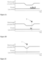
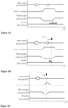
- the sensing pad and the ground pad move closer to human bite as illustrated in Figure 8B .
- the dental appliance comprising one or more sensor 26 is placed in the mouth, the human bite compresses the elastic material 16 of the sensor and the distance between the ground pad and the sensing pad changes.
- the dental load due to the human bite on the substrate can be qualitatively or quantitatively measured and monitored by a device assembly as described herein.
- a capacity increase is measured when biting load increases.
- a resistance decrease is measured when the bite load increases, as expected by the Ohm's Law.
- the elastic material 16 separating the sensing pad and the ground pad in the sensor are dielectric and the integrated circuit 10 performs capacitive measurements between the sensing pad and the ground pad.
- the sensing pad and the ground pad get closer, compressing the dielectric material.
- the dental load applied on the dental appliance may be estimated by a device assembly as described herein using Hooke's law. The presence of the shielding pad increases the sensitivity of the measurement and reduces the effect of external disturbances on the sensing pads.
- the elastic material 16 of the sensor under pressure or bite pressure, the elastic material 16 of the sensor is compressed and the sensing pad 14 moves closer to the ground pad 12, modifying the mutual capacitance and/or electrical resistance between the sensing pad and the ground pad, and generating a dental forces signal conducted through the integrated circuit 10 to the transmitter and/or receiver means and/or to the data storage means.
- the dielectric substrate 8 is a single body or a layer assembly that hosts and keeps in place the sensing parts of the sensor 26 being one or more sensing pads 14 and one or more ground pads 12, the signal processing part being one or more integrated circuit 10 and their electrical connections being electric lines 15. Electronics and sensory parts are manufactured on the same dielectric substrate using the same technological processes without extra soldering processes, which represent an advantageous manufacturing and assembly process and allowing increasing the quality of the electro-mechanical properties of the dental appliance such as mechanical tolerances, electrical noise level and reproducibility of the measurements.
- the dental appliance presents an overall elasticity because of the materials of dielectric substrate.
- the material in between the ground pad and the sensing pad is elastic, at least in the range of physiological and supraphysiological human bite loads, the deformation behaviour of the substrate under compressive load is repeatable yielding repeatable measurements and thus overcoming existing problems associated with the elevated hysteresis of existing intraoral sensors. Due to the dielectric substrate configuration and the elasticity of the materials in the inter-occlusal region, the measurements of the bruxism can be precise, accurate, quantitative, reliable and repeatable both for static and dynamic bite closure.
- the dental appliance is made of a material which may be Ethyl Vinyl Acetate (EVA).
- human bite or “bite” or “bite closure” or “bite occlusion” refer to the movement that let the upper and lower teeth meet when the jaw is closed. More specifically, it is the static or dynamic relationship between the maxillary (upper) and mandibular (lower) teeth when they approach each other, as occurs during, e.g., chewing or at rest.
- Static bite refers to the situation when forces are applied to the jaw and the jaw is closed and stationary
- dynamic bite also termed as articulation refers to jaw movements when the jaw is moving. These movements are intended in presence of inter-occlusal materials as well as in absence of inter-occlusal materials.
- two or more sensors 26 are linked with each other through a portion of the dielectric substrate, said portion of the dielectric substrate comprising one or more electric areas 9 and/or integrated circuit 10 as illustrated in Figure 7B .
- the shape of the dielectric substrate can be designed to reduce the mechanical stress in the material of the dielectric substrate upon bending and upon dental load. Holes and metal appendices can be patterned on the substrate for the same purpose.
- the dielectric substrate 8 is foldable and embedded in the dental appliance having an outer side 28, a sensor side 27 and an inner side 29, and, when said dental appliance is placed in the mouth, the outer side covers the buccal tooth surface, the sensor side covers the occlusal or incisal tooth surface and the inner side covers the lingual tooth surface and/or the palate.
- the one or more electric areas 9 are on said outer side 28 or on said inner side 29 of the dental appliance and the sensors are on said sensor side 27 of the dental appliance.
- the expression "on” does not limit the position of the one or more electric areas 9 to the inner or outer surface of said respective outer, inner or sensor side of the dental appliance. Said one or more electric areas can be embeddable into the material of the dental appliance.
- Such embodiments are illustrated in Figure 9 , dielectric substrate embedded in the appliance, as well as in Figure 7B , folded dielectric substrate not being embedded or included in a dental appliance.
- the dental appliance fits the mandibular arch or fits the maxillary dental arch and/or the palate, the sensors 26 being on the sensor side 27 and/or directed on the occlusal and/or incisal tooth surface.
- the dental appliance fitted the dental arch and/or the palate of the superior maxillary may comprise a dielectric substrate 8, wherein one or more electric areas are on a portion 30 of the dielectric substrate fitted the palate as illustrated in Figure 7C connecting at least two sensors 26.
- Said dental appliance for the superior maxillary may have an inner side covering totally the lingual tooth surface and the palate or partially the lingual tooth surface and the palate, fitting only a part of the dental arch.
- the dental appliance further comprises one or more transmitter and/or receiver means 221, such as Bluetooth LE, one or more data storage means 222, such as flash memory or EEPROM memory, and a battery power source 23, such as Lithium polymer battery.
- a dental appliance is illustrated in Figure 9 .
- the battery is preferably a rechargeable battery.
- the dental appliance further comprises circuitry to recharge the battery.
- the battery is wirelessly recharged in order to maintain the dental appliance insulated and waterproof.
- the integrated circuit 10 connected to the sensing pad measures the mutual capacitance and/or the electrical resistance between said sensing pad and the ground pad, generating a signal being conducted to the transmitter and/or receiver means and/or to the data storage means.
- the mechanical load evaluated by the sensing pad is used to determine the condition of bruxism during sleep or wakefulness.
- a threshold or a time interval duration or both can be used to characterize the condition of bruxism.
- Multiple sensing pads can be designed in the same substrate to cover different biting regions on the dental arch.
- the load gathered on the different sensing pads can be used to discriminate clenching of the jaw or maxillary from grinding or gnashing of the jaw or maxillary.
- the dynamics of the bite closure such as force intensity, unbalances, direction of grinding, duration of events, sequence of events, types of bruxism pattern, is assessed by evaluating the load on the different sensing pads over time.
- the shape of the sensing pad and the mutual disposition of different sensing pads on the dielectric substrate are used to better evaluate the dynamics of the bite closure.
- the dental appliance is used for monitoring dental contact, dental forces, and/or for detecting teeth clenching and/or grinding.
- the present invention also relates to a device and a method to accurately evaluate patient sleep and the patient sleeping state in order to anticipate the bio-feedback response before bruxism events occur.
- This can be obtained by recording one or more patient parameters, continually correlating these data, evaluating the sleep state of the patient and triggering a bio-feedback action that anticipates in time a bruxism event.
- the bio-feedback can be activated as a consequence of bruxism detection.
- the bio-feedback action can be terminated after a determinate amount of time or as soon as the sleep parameters return at normal/nominal levels.
- the present invention also relates to a device assembly for reducing teeth clenching and/or grinding and/or preventing bruxism comprising a sensing unit 1 for detecting teeth clenching and/or grinding, a biofeedback unit 2, at least one auxiliary unit 3, and a signal processing means, characterized in that said sensing unit, said biofeedback unit, said at least one auxiliary unit and said signal processing means are included in one device or in two or more devices; in that the at least one auxiliary unit is a sensor for measuring one or more sensor signals selected from respiratory airflow, snoring, blood oxygen saturation, pH, blood pressure, heart rate, electrocardiographic activity, electroencephalographic activity, body temperature, body position, body movement, and eye movement; in that the signal processing means comprises a receiver means to detect one or more sensor signals, and/or one or more dental forces signals, a monitoring means to detect the variation of the intensity and/or the frequency of said signals vs.
- the biofeedback unit is a responsive means in communication with the signal processing means and responding to the action signal and is selected from means providing vibrating signal, tactile signal, acoustic signal, electrical stimulation signal and/or optical signal.
- the sensing unit 1 of the device assembly for reducing teeth clenching and/or grinding and/or preventing bruxism may comprise a masticatory muscle activity monitoring unit or jaw activity monitoring unit and/or dental forces monitoring unit.
- the masticatory unit may be included in the same device as the device included the sensing unit 1, the biofeedback unit 2, the at least one auxiliary unit 3 and/or the signal processing means.
- the masticatory muscle monitor unit comprises one or more electrodes and/or one or more intra-oral sensors measuring electromyography (EMG) signal.
- EMG electromyography
- the signal processing means comprises a receiver means to detect one or more EMG signals, one or more sensor signals, and/or one or more dental forces signals, a monitoring means to detect the variation of the intensity and/or the frequency of said signals vs. time, and a transmitter means to generate an action signal in response to said variation of said EMG signals, said sensor signals and/or said dental forces signals.
- the biofeedback unit 2 is a responsive means in communication with the signal processing means and responding to the action signal and is selected from means providing vibrating signal, tactile signal, acoustic signal and/or optical signal.
- the sensing unit 1 comprises the dental appliance 4.
- the dental appliance may be used as dental forces monitoring unit.
- the sensing unit may be then integrated in the dental appliance comprising the sensors or the sensors for bruxism detection.
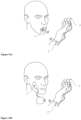
- the biofeedback unit 2 and the at least one auxiliary unit 3 and/or the signal processing means may be integrated in the dental appliance or in one or more further devices. Such embodiment is illustrated by Figure 1A-D .
- the dental appliance 4 further comprises the sensing unit 1, the biofeedback unit 2 and/or the at least one auxiliary unit being on a second and/or a third device selected from wearable devices: band, wristband and/or captor or sensor wearable by a body part.
- the sensing unit 1, the bio-feedback unit 2 and the auxiliary unit 3 may be included in an electronic board inside the dental appliance 4.
- said masticatory muscle activity or jaw activity monitoring unit may be included in the dental appliance 4, whereas the biofeedback unit 2 and the auxiliary unit 3 are included in a watch or bracelet or wristband.
- the masticatory muscle activity or jaw activity monitoring unit and the auxiliary unit 3 are included in the dental appliance 4, whereas the bio-feedback unit 2 is integrated into the bracelet or watch or wristband.
- the masticatory muscle activity or jaw activity monitor unit is included in the dental appliance 4, the bio-feedback unit 2 is integrated into the bracelet or watch or wristband and the auxiliary unit 3 is wirelessly connected to the bracelet or watch or wristband.
- Wearable devices may be selected from, but not limited to, bracelet, watch, wristwatch, band, chest belt, head belt, ring, chest strip, head strip, rings, smartphone, and portable.
- the sensing unit 1 may comprises a masticatory muscle activity or jaw activity monitoring unit being separated from the dental forces monitoring unit or integrated in a further wearable device as defined above, said dental forces monitoring unit being integrated in or being the dental appliance, and said masticatory muscle activity or jaw activity monitoring unit being wirelessly connected with the dental appliance, the biofeedback unit and/or the auxiliary unit.
- the masticatory muscle activity monitor unit is included in the dental appliance.
- Intraoral sensors integrated or included in the smart appliance are used to detect the jaw activity. Bruxism is detected by force sensors or transducers integrated into the dental appliance 4.
- the sensing unit 1, the bio-feedback unit 2, the signal processing means, and the at least one auxiliary unit 3 can be physically connected with wires, electrical lines or conductive traces and/or wirelessly connection such as radio means.
- the sensing unit 1 electronically measures and evaluates the activity of the patient jaw.
- Said monitor unit 1 provides a signal when the patient clenches, taps or grinds the teeth through EMG measurements (electromyography) or through the intraoral sensors or force transducer included in the dental appliance 4 and measuring dental biting forces.
- the jaw activity can be measured qualitatively or quantitatively.
- the bio-feedback unit 2 provides an alert signal or a stimulus in response to the received signal from the signal processing means receiving the signals from the sensing unit, the intraoral sensor, the masticatory muscle activity monitor, and/or the auxiliary unit, or from all, one or more units, sensor or monitor, prior and/or during a bruxism event, preferably prior to said event.
- the alert signal or stimulus is provided to a means to vibrate and/or to operate in a tactile manner, acoustically, optically and/or electrically.
- Said means may be a part of the biofeedback unit or is connected to the biofeedback unit wirelessly or through electric lines. Multiple bio-feedback signals (i.e. acoustic and vibration) can be combined to alert or signal the same event.
- Said signals are provided to the user of the device assembly or to a further monitor.
- the signal processing means can also post-process the data provided by the sensors and can be used for generating a report on the analysis of the bruxism, sleep and/or awake conditions.
- Said means integrates the different signals for one or more sensors in function of time or versus (vs.) time and detects variations.
- Said data may be processed by the monitoring means of the signal processing means.
- the auxiliary unit is a sensor measuring at least one of the following body parameters: respiratory airflow, snoring activity, blood oxygen saturation, blood pressure, acid concentration, acid presence, pH, oral internal temperature, body temperature, blood pressure, heart rate, electroencephalographic activity, electrocardiographic activity, eyes movements, and movements.
- a single sensor in one auxiliary unit may provide information on multiple parameters.
- a pulse oximeter, e.g., sensor can provide information on blood oxygen saturation, blood pressure and heart rate.
- the analysis of the measurements of one or more of these parameters and their integration versus time, the recording of any variation of these parameters and their integration compared with a threshold determined in conditions without bruxism provide information to determine the state of the patient at a specific moment or during a period. This analysis is performed in the signal processing means or unit in order to provide the system with data that inform the bio-feedback unit and activates it before the occurrence of bruxism events.
- the wording "operatively connected”, “operatively connectable” or even “operatively connecting”, reflects a functional relationship between two or more components of a device or a system, that is, such a wording means that the claimed components must be connected in a way to perform a designated function.
- the "designated function” can change depending on the different components involved in the connection; for instance, the designated function of a microcontroller unit operatively connected to a display system is the (re-)elaboration and dispatch of the data relative to dental occlusion and/or clenching coming from the sensor to said display system.
- the designated function of transmission conductive lines operatively connecting a capacitive pad to a microcontroller unit is the transmission of an electrical signal from one component (the sensor pad) to another (the microcontroller).
- the connection can be physical or wireless; for instance, the "designated function" of a wireless connection operatively connecting a mobile device to a wearable device is the transmission of an electromagnetic signal (e.g. to exchange data) from one device (the mobile device) to another (the smart appliance).
- the transmitter means of the signal processing means in the device assembly for reducing teeth clenching and/or grinding and preventing bruxism generates the action signal in response to the variation of EMG signals and/or sensor signals to actuate the biofeedback unit 2 before detecting a variation of the intensity and/or frequency of the dental forces signals vs. time and/or detecting teeth clenching and/or grinding.
- the biofeedback unit 2 in the device assembly for reducing teeth clenching and/or grinding and/or preventing bruxism is actuated in response of the action signal providing by the signal processing means detecting a variation of the intensity and/or the frequency of EMG signals.
- the transmitter means of the signal processing means in the device assembly for reducing teeth clenching and/or grinding and/or preventing bruxism generates the action signal in response to the variation of the intensity and/or frequency of dental forces signals vs. time.
- the dental forces signals from the sensing unit are monitored after actuating the biofeedback unit 2 in response to the variation of EMG signals and/or sensor signals.
- the biofeedback unit is activated to suppress any residual variation of the dental forces signal or bruxism.
- the sensor signals are selected from electroencephalographic activity, heart rate and blood oxygen saturation.
- the present invention also provides a method for reducing teeth clenching and/or grinding and/or preventing bruxism comprising the steps of
- the method for reducing teeth clenching and/or grinding and/or preventing bruxism may further comprise a step of obtaining a signal of the bruxism activity through measures with one or more electrodes and/or one or more intra-oral sensors, and/or a step of obtaining EMG signal of masticatory muscles activity through measures with one or more electrodes and/or one or more intra-oral sensors. Said steps may be prior or after the step of obtaining at least one sensor signal.
- the method involving a step of obtaining a signal of bruxism activity and/or EMG signals comprises a step of processing EMG signals and at least one sensor signal and determining at least a variation of the intensity and/or the frequency of said signals vs. time, and/or providing a stimulus selected from vibrating signal, tactile signal, acoustic signal and/or optical signal in response to the variation of the intensity and/or the frequency of said EMG signals and said at least one sensor signal vs. time.
- the variation is determined according to a threshold of the particular signal measured in conditions without bruxism.
- body parameters e.g. but not limited to heart rate, blood oxygen saturation
- the heart rate variation in time is minimal, about 2% per minute, as well as the oxygen saturation assume value greater than 95%.
- the heart rate changes, i.e. significantly increases in one minute (short time interval), e.g. from 55 beats per minute (bpm) to 65 bpm in one minute.
- the oxygen saturation in blood significantly drops in one minute (short time interval), e.g. from ⁇ 95% to ⁇ 91% in one minute.
- Said variations occur in an 8-minute time window before a bruxism event.
- the method described herein may be used for reducing teeth clenching and/or grinding and/or preventing bruxism by the occurrence of a bruxism event.
- the activation of a biofeedback unit may be triggered prior to the occurrence of bruxism.
- the method of the invention to prevent bruxism comprises further steps of obtaining dental forces signals by measuring teeth pressure, processing dental forces signals and determining a variation of the intensity and/or the frequency of said dental forces signals vs. time.
- the dental forces signals are obtained by the dental appliance 4.
- the dental forces may be monitored during the monitoring or the steps of obtaining the EMG signals or one or more signals from one or more auxiliary units and/or after the step of providing a stimulus.
- the action signal or stimulus from biofeedback unit is provided before the beginning of the bruxism or the occurrence of the bruxism episodes.
- the biofeedback unit may be also activated or actuated by receiving solely the information provided by the jaw activity monitoring unit without being activated by the signals provided by the sensing unit and/or by the auxiliary units. This prevents unexpected and unpredicted bruxism events to cause excessive damage to the teeth of the user.
- the device assembly may be used also for triggering the biofeedback unit upon bruxism detection of said residual bruxism event. This will shorten the duration of the detected event and prevent successive events from occurring.
- the activation of the biofeedback unit before the occurrence of bruxism episodes and/or in response to unpredictable bruxism episodes allows to reduce the mechanical overload induced by bruxism on teeth and dental prostheses and/or, secondary effects encountered shortly before bruxism such as increased blood pressure, oxygen desaturation in blood and tachycardia, which may also improve the overall quality of the user sleep.
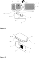
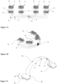
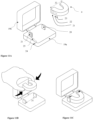
- the present invention also provides a dental appliance storage case or housing piece that wirelessly charges the dental appliance's battery and maintains the dental appliance in charging mode by applying elastic deformation to the whole appliance or to one of its parts as illustrated in Figures 11B-11C and 12B .
- the dental appliance storage case comprises a base 19a; a cover hinged 19b to the base; two appendices 20 orientated normal to the base 19a; characterized in that
- the dental appliance is maintained in-between said two appendices during the charging of the battery and/or transport, the area comprising the coil at the end of the dental appliance matching with the area comprising the coil of the appendix.
- the dental appliance comprising a storage means 22 is operatively connected to the module 25 of the storage case and/or with a mobile device to exchange data.
- the appendices normal to the base of the storage case constrain, align or guide the dental appliance by elastically deforming it and forcing it to be placed in-between.
- Such position is a charging position and thus allows the splint to be held in place and stably maintained in charge mode. Being the splint kept in a well-defined position inside the storage case, the wireless charge is more efficient, the splint material does not overheat and any little inadvertent, undesired or unwanted bump or shake of the storage case does neither stop, nor interrupt the charging process of the splint, and does not affect the efficiency of the charging process itself.
- the base may comprise four appendices normal to the base, two appendices being placed on both sides (inner and outer sides) of the dental appliance ends as illustrated in Figure 12C .
- the inner sides and outer sides of the ends of the dental appliance are squeezed each between said two appendices.
- One or two appendices may comprise the coil 21 for charging the battery of exchanging data, said one or two appendices comprising the coil 21 being towards the external side of the case
- the storage case is being made of plastic.
- the charging circuit is composed by a DC (direct current) power supply, by an oscillator and a coil.
- the charging circuit is embedded in the storage case.
- the module exchanging data with the charging circuit stabilizes the voltage, and a battery. This circuit is embedded in the dental appliance.
Landscapes
- Health & Medical Sciences (AREA)
- Life Sciences & Earth Sciences (AREA)
- Veterinary Medicine (AREA)
- Heart & Thoracic Surgery (AREA)
- Public Health (AREA)
- General Health & Medical Sciences (AREA)
- Animal Behavior & Ethology (AREA)
- Engineering & Computer Science (AREA)
- Biomedical Technology (AREA)
- Pathology (AREA)
- Medical Informatics (AREA)
- Molecular Biology (AREA)
- Surgery (AREA)
- Physics & Mathematics (AREA)
- Biophysics (AREA)
- Cardiology (AREA)
- Physiology (AREA)
- Dentistry (AREA)
- Pulmonology (AREA)
- Orthopedic Medicine & Surgery (AREA)
- Physical Education & Sports Medicine (AREA)
- Oral & Maxillofacial Surgery (AREA)
- Otolaryngology (AREA)
- Nursing (AREA)
- Vascular Medicine (AREA)
- Psychology (AREA)
- Rheumatology (AREA)
- Psychiatry (AREA)
- Dental Tools And Instruments Or Auxiliary Dental Instruments (AREA)
- Measuring And Recording Apparatus For Diagnosis (AREA)
- Measurement And Recording Of Electrical Phenomena And Electrical Characteristics Of The Living Body (AREA)
- Measurement Of The Respiration, Hearing Ability, Form, And Blood Characteristics Of Living Organisms (AREA)
Claims (10)
- Appareil dentaire (4) comprenant
un substrat diélectrique (8) comprenant- une ou plusieurs zones électriques (9) comprenant un ou plusieurs circuits intégrés (10) et une ou plusieurs lignes électriques (15)- une ou plusieurs zones de masse (11) comprenant un ou plusieurs plots de masse (12),- une ou plusieurs zones de détection (13) comprenant un ou plusieurs plots de détection (14),caractérisé en ce que- la ou les zones électriques (9), la ou les zones de masse (11), et la ou les zones de détection (13) sont logées sur le même substrat diélectrique (8) qui est d'une seule pièce comprenant un matériau diélectrique ;- une ou plusieurs sections du substrat diélectrique sont courbées ;- une zone de détection fait face à une zone de masse ;- ladite zone de détection faisant face à une zone de masse est séparée par une couche comprenant un matériau élastique (16) qui est diélectrique et forme un capteur (26) ; et- le ou les circuits intégrés effectuent des mesures capacitives entre le ou les plots de détection et le ou les plots de masse. - L'appareil dentaire (4) selon la revendication 1, la ou les zones électriques (9), les zones de masse (11) et les zones de détection (13) étant logées sur le même côté du substrat diélectrique, ledit côté étant le côté avant (8a).
- L'appareil dentaire (4) selon l'une quelconque des revendications précédentes, caractérisé en ce que le ou les plots de masse (12) et le ou les plots de détection (14) sont connectés électriquement à un ou plusieurs circuits intégrés par l'intermédiaire des lignes électriques.
- L'appareil dentaire (4) selon l'une quelconque des revendications précédentes, caractérisé en ce que deux ou plus de deux capteurs (26) sont reliés entre eux par une partie du substrat diélectrique, ladite partie du substrat diélectrique comprenant un ou plusieurs zones électriques et/ou circuits intégrés.
- L'appareil dentaire (4) selon l'une quelconque des revendications précédentes, caractérisé en ce que le substrat diélectrique est pliable et incorporé dans l'appareil dentaire ayant un côté extérieur (28), un côté capteur (27) et un côté intérieur (29), et, lorsque ledit appareil dentaire est placé dans la bouche, le côté extérieur couvre la surface buccale de la dent, le côté capteur couvre la surface occlusale ou incisive de la dent et le côté intérieur couvre la surface linguale de la dent et/ou le palais ; et, et en ce que la ou les zones électriques sont sur ledit côté extérieur ou sur ledit côté intérieur de l'appareil dentaire et les capteurs sont sur ledit côté capteur de l'appareil dentaire.
- L'appareil dentaire (4) selon l'une quelconque des revendications précédentes, caractérisé en ce que l'appareil dentaire s'adapte à l'arc dentaire mandibulaire ou s'adapte à l'arc dentaire maxillaire et/ou au palais, les capteurs étant sur la surface occlusale et/ou incisive des dents.
- L'appareil dentaire (4) selon l'une quelconque des revendications précédentes comprenant en outre un ou plusieurs moyens émetteurs et/ou récepteurs (221), un ou plusieurs moyens de stockage de données (222), et une source d'alimentation par batterie (23).
- L'appareil dentaire (4) selon l'une quelconque des revendications précédentes, caractérisé en ce que le circuit intégré connecté au plot de détection mesure la capacité mutuelle entre ledit plot de détection et le plot de masse, générant un signal qui est conduit aux moyens émetteurs et/ou récepteurs et/ou aux moyens de stockage de données.
- L'appareil dentaire (4) selon l'une quelconque des revendications précédentes, caractérisé en ce que, sous l'effet d'une pression ou d'une pression de morsure, le matériau élastique du capteur est comprimé et le plot de détection se rapproche du plot de masse, modifiant la capacité mutuelle entre le plot de détection et le plot de masse, et générant un signal de forces dentaires conduit à travers le circuit intégré aux moyens émetteurs et/ou récepteurs et/ou aux moyens de stockage de données.
- L'appareil dentaire (4) selon l'une quelconque des revendications précédentes utilisé pour surveiller le contact dentaire, les forces dentaires, et/ou pour détecter le serrement et/ou le grincement des dents.
Priority Applications (1)
| Application Number | Priority Date | Filing Date | Title |
|---|---|---|---|
| EP22213575.8A EP4169491A1 (fr) | 2017-12-22 | 2018-12-18 | Dispositifs et procédé de gestion du bruxisme |
Applications Claiming Priority (2)
| Application Number | Priority Date | Filing Date | Title |
|---|---|---|---|
| IB2017058358 | 2017-12-22 | ||
| PCT/IB2018/060229 WO2019123232A1 (fr) | 2017-12-22 | 2018-12-18 | Dispositifs et procédé de gestion de bruxisme |
Related Child Applications (2)
| Application Number | Title | Priority Date | Filing Date |
|---|---|---|---|
| EP22213575.8A Division-Into EP4169491A1 (fr) | 2017-12-22 | 2018-12-18 | Dispositifs et procédé de gestion du bruxisme |
| EP22213575.8A Division EP4169491A1 (fr) | 2017-12-22 | 2018-12-18 | Dispositifs et procédé de gestion du bruxisme |
Publications (2)
| Publication Number | Publication Date |
|---|---|
| EP3727248A1 EP3727248A1 (fr) | 2020-10-28 |
| EP3727248B1 true EP3727248B1 (fr) | 2023-02-15 |
Family
ID=65278410
Family Applications (2)
| Application Number | Title | Priority Date | Filing Date |
|---|---|---|---|
| EP22213575.8A Pending EP4169491A1 (fr) | 2017-12-22 | 2018-12-18 | Dispositifs et procédé de gestion du bruxisme |
| EP18842836.1A Active EP3727248B1 (fr) | 2017-12-22 | 2018-12-18 | Dispositif et methode pour le traitement du bruxisme |
Family Applications Before (1)
| Application Number | Title | Priority Date | Filing Date |
|---|---|---|---|
| EP22213575.8A Pending EP4169491A1 (fr) | 2017-12-22 | 2018-12-18 | Dispositifs et procédé de gestion du bruxisme |
Country Status (8)
| Country | Link |
|---|---|
| US (1) | US11596540B2 (fr) |
| EP (2) | EP4169491A1 (fr) |
| JP (1) | JP7448221B2 (fr) |
| CN (1) | CN111698973A (fr) |
| CA (1) | CA3084736A1 (fr) |
| DK (1) | DK3727248T3 (fr) |
| ES (1) | ES2942275T3 (fr) |
| WO (1) | WO2019123232A1 (fr) |
Families Citing this family (8)
| Publication number | Priority date | Publication date | Assignee | Title |
|---|---|---|---|---|
| WO2020132548A2 (fr) | 2018-12-20 | 2020-06-25 | Gonzales Anthony M | Protège-dents à caractéristique de notification d'utilisateur de force de choc et son procédé de fabrication |
| WO2021014860A1 (fr) * | 2019-07-22 | 2021-01-28 | 株式会社村田製作所 | Capteur de cavité buccale |
| CA3156309A1 (fr) * | 2019-11-04 | 2021-05-14 | Reza Radmand | Dispositif et procede d'electro-encephalographie intra-orale |
| WO2022109175A1 (fr) * | 2020-11-19 | 2022-05-27 | Smrt Mouth Inc. | Dispositif intra-oral, système et procédé de surveillance intra-oral |
| EP4070759A1 (fr) * | 2021-04-09 | 2022-10-12 | Koninklijke Philips N.V. | Embout buccal pour un dispositif de soins oraux |
| US20230240802A1 (en) * | 2022-01-28 | 2023-08-03 | PerioTech, LLC | Devices and methods of treating sleep and awake bruxism |
| WO2023200845A1 (fr) * | 2022-04-12 | 2023-10-19 | Hawkeye Group, LLC | Systèmes, appareils et procédés de traitement de bruxisme, d'apnée et de troubles du sommeil |
| WO2024192395A1 (fr) * | 2023-03-16 | 2024-09-19 | Google Llc | Détection et/ou classification de comportement humain à l'aide d'une détection acoustique active |
Family Cites Families (26)
| Publication number | Priority date | Publication date | Assignee | Title |
|---|---|---|---|---|
| US4146130A (en) * | 1977-04-08 | 1979-03-27 | Samuels Peter B | Hemostatic clip, clip applicator and cartridge therefor |
| US4734034A (en) * | 1985-03-29 | 1988-03-29 | Sentek, Incorporated | Contact sensor for measuring dental occlusion |
| US4856993A (en) * | 1985-03-29 | 1989-08-15 | Tekscan, Inc. | Pressure and contact sensor system for measuring dental occlusion |
| US6089864A (en) * | 1997-11-14 | 2000-07-18 | William L. Hintermister | Bio-feedback, data acquisition teeth guards, methods of their manufacture and use |
| US6511441B1 (en) | 1998-08-19 | 2003-01-28 | Advanced Telecommunications Research Institute International | System for measuring tongue pressure |
| FR2820308B1 (fr) * | 2001-02-08 | 2004-08-27 | Eric Dutertre | Dispositif orthodontique et ses procedes de fabrication |
| JP2005097277A (ja) * | 2003-08-21 | 2005-04-14 | Teruko Yamamoto | 歯ぎしりの予防剤または治療剤 |
| NL2000850C2 (nl) * | 2007-09-10 | 2009-03-11 | Bruxtec B V | Inrichting voor het detecteren van symptomatisch kaakgedrag. |
| US8961437B2 (en) * | 2009-09-09 | 2015-02-24 | Youhanna Al-Tawil | Mouth guard for detecting and monitoring bite pressures |
| JP2010099368A (ja) * | 2008-10-27 | 2010-05-06 | Panasonic Corp | 歯科用印象収納容器 |
| CN201308557Y (zh) * | 2008-12-02 | 2009-09-16 | 南通同润生物科技有限公司 | 生物反馈治疗磨牙症装置 |
| CN101569778B (zh) * | 2009-03-10 | 2011-06-22 | 深圳先进技术研究院 | 生物反馈刺激系统 |
| CN101797192A (zh) * | 2009-12-30 | 2010-08-11 | 同济大学 | 一种改良三叉神经伤害抑制-压力缓解系统咬合板及其使用方法 |
| CN201642503U (zh) * | 2010-03-11 | 2010-11-24 | 南方医科大学 | 基于生物反馈的监测治疗装置 |
| US8690800B2 (en) * | 2010-05-18 | 2014-04-08 | Erik Lillydahl | Systems and methods for reducing subconscious neuromuscular tension including bruxism |
| DE202011102064U1 (de) | 2011-06-21 | 2011-10-19 | Bianca Berk | Zahnaufsatz |
| US10517525B2 (en) | 2013-01-14 | 2019-12-31 | University Of Florida Research Foundation, Inc. | Smart diagnostic mouth guard system |
| GB201317478D0 (en) | 2013-10-02 | 2013-11-13 | Provost Fellows Foundation Scholars And The Other Members Of Board Of The | A sensor for an oral appliance |
| US11064913B2 (en) * | 2013-10-25 | 2021-07-20 | Force Impact Technologies, Inc. | Impact sensing wearable device and method |
| MY178689A (en) * | 2014-05-07 | 2020-10-20 | Sunstar Suisse Sa | Automatic detection of teeth clenching and/or teeth grinding |
| JP6427434B2 (ja) * | 2015-02-06 | 2018-11-21 | マニー株式会社 | 歯科用器具収納ケース |
| US11109808B2 (en) * | 2015-10-23 | 2021-09-07 | University Of Florida Research Foundation, Inc. | Intelligent fitness and sports mouthguard |
| US10470921B2 (en) * | 2016-04-07 | 2019-11-12 | Achaemenid, Llc | Removable mandibular myo-stimulator |
| CN206403874U (zh) * | 2016-09-30 | 2017-08-15 | 杭州沃开尼克科技有限公司 | 一种新型智能电动牙刷及电动牙刷组件 |
| CN106388783B (zh) * | 2016-10-20 | 2024-02-06 | 北京大众益康科技有限公司 | 磨牙症检测装置、系统及睡眠波形数据的分析处理方法 |
| CN206372036U (zh) * | 2016-10-20 | 2017-08-04 | 山东大众益康网络科技有限公司 | 磨牙症检测装置及系统 |
-
2017
- 2017-12-22 US US16/955,447 patent/US11596540B2/en active Active
-
2018
- 2018-12-18 ES ES18842836T patent/ES2942275T3/es active Active
- 2018-12-18 CN CN201880081305.6A patent/CN111698973A/zh active Pending
- 2018-12-18 EP EP22213575.8A patent/EP4169491A1/fr active Pending
- 2018-12-18 JP JP2020554593A patent/JP7448221B2/ja active Active
- 2018-12-18 EP EP18842836.1A patent/EP3727248B1/fr active Active
- 2018-12-18 DK DK18842836.1T patent/DK3727248T3/da active
- 2018-12-18 CA CA3084736A patent/CA3084736A1/fr active Pending
- 2018-12-18 WO PCT/IB2018/060229 patent/WO2019123232A1/fr unknown
Also Published As
| Publication number | Publication date |
|---|---|
| CN111698973A (zh) | 2020-09-22 |
| EP3727248A1 (fr) | 2020-10-28 |
| JP2021509078A (ja) | 2021-03-18 |
| US20200345536A1 (en) | 2020-11-05 |
| CA3084736A1 (fr) | 2019-06-27 |
| WO2019123232A1 (fr) | 2019-06-27 |
| EP4169491A1 (fr) | 2023-04-26 |
| DK3727248T3 (da) | 2023-04-11 |
| US11596540B2 (en) | 2023-03-07 |
| JP7448221B2 (ja) | 2024-03-12 |
| ES2942275T3 (es) | 2023-05-31 |
Similar Documents
| Publication | Publication Date | Title |
|---|---|---|
| EP3727248B1 (fr) | Dispositif et methode pour le traitement du bruxisme | |
| CN113616362B (zh) | 利用感测的口内器具 | |
| CN107518952B (zh) | 利用感测的口内器具 | |
| US6554781B1 (en) | Spinal monitor apparatus and method | |
| US10517525B2 (en) | Smart diagnostic mouth guard system | |
| US6270466B1 (en) | Bruxism biofeedback apparatus and method including acoustic transducer coupled closely to user's head bones | |
| JP5389278B2 (ja) | 埋め込み可能医療デバイスのための感圧外部充電器 | |
| CN204708829U (zh) | 一种无线呼吸、脉搏监测装置 | |
| JP2001519207A (ja) | データ取得成分を含む眼帯 | |
| US20190343452A1 (en) | Bruxism monitoring and prevention system | |
| US20210052213A1 (en) | Sensor Apparatus for Measurement of Muscle Activity in the Detection & Treatment of Bruxism Disorder | |
| WO2008061328A2 (fr) | Gouttière occlusale pour un conditionnement parafonctionnel | |
| US11412973B2 (en) | Modular garment for a wearable medical device | |
| US11007076B1 (en) | Bruxism mouth guard device and system including the same | |
| WO2017117739A1 (fr) | Système de surveillance de sommeil | |
| US10820853B2 (en) | Sensor and apparatus for measurement of muscle activity in the detection and treatment of Bruxism Disorder | |
| Kim et al. | Development of bite guard for wireless monitoring of bruxism using pressure-sensitive polymer | |
| EP3599998B1 (fr) | Appareil buccal | |
| EP3506822B1 (fr) | Entraîneur de sommeil avec bande de mesure de fréquence cardiaque | |
| US20240268992A1 (en) | Apparatuses and methods involving a mouthpiece for treating medical condition(s) and/or sleep monitoring | |
| Kim et al. | Development of a wireless autonomous bruxism monitoring device | |
| Dossey et al. | Bruxism Biofeedback Device | |
| AU769371B2 (en) | Spinal monitor apparatus and method |
Legal Events
| Date | Code | Title | Description |
|---|---|---|---|
| STAA | Information on the status of an ep patent application or granted ep patent |
Free format text: STATUS: UNKNOWN |
|
| STAA | Information on the status of an ep patent application or granted ep patent |
Free format text: STATUS: THE INTERNATIONAL PUBLICATION HAS BEEN MADE |
|
| PUAI | Public reference made under article 153(3) epc to a published international application that has entered the european phase |
Free format text: ORIGINAL CODE: 0009012 |
|
| STAA | Information on the status of an ep patent application or granted ep patent |
Free format text: STATUS: REQUEST FOR EXAMINATION WAS MADE |
|
| 17P | Request for examination filed |
Effective date: 20200708 |
|
| AK | Designated contracting states |
Kind code of ref document: A1 Designated state(s): AL AT BE BG CH CY CZ DE DK EE ES FI FR GB GR HR HU IE IS IT LI LT LU LV MC MK MT NL NO PL PT RO RS SE SI SK SM TR |
|
| AX | Request for extension of the european patent |
Extension state: BA ME |
|
| DAV | Request for validation of the european patent (deleted) | ||
| DAX | Request for extension of the european patent (deleted) | ||
| GRAP | Despatch of communication of intention to grant a patent |
Free format text: ORIGINAL CODE: EPIDOSNIGR1 |
|
| STAA | Information on the status of an ep patent application or granted ep patent |
Free format text: STATUS: GRANT OF PATENT IS INTENDED |
|
| INTG | Intention to grant announced |
Effective date: 20220908 |
|
| GRAS | Grant fee paid |
Free format text: ORIGINAL CODE: EPIDOSNIGR3 |
|
| GRAA | (expected) grant |
Free format text: ORIGINAL CODE: 0009210 |
|
| STAA | Information on the status of an ep patent application or granted ep patent |
Free format text: STATUS: THE PATENT HAS BEEN GRANTED |
|
| AK | Designated contracting states |
Kind code of ref document: B1 Designated state(s): AL AT BE BG CH CY CZ DE DK EE ES FI FR GB GR HR HU IE IS IT LI LT LU LV MC MK MT NL NO PL PT RO RS SE SI SK SM TR |
|
| REG | Reference to a national code |
Ref country code: CH Ref legal event code: EP Ref country code: GB Ref legal event code: FG4D |
|
| REG | Reference to a national code |
Ref country code: DE Ref legal event code: R096 Ref document number: 602018046242 Country of ref document: DE |
|
| REG | Reference to a national code |
Ref country code: AT Ref legal event code: REF Ref document number: 1547871 Country of ref document: AT Kind code of ref document: T Effective date: 20230315 Ref country code: IE Ref legal event code: FG4D |
|
| REG | Reference to a national code |
Ref country code: DK Ref legal event code: T3 Effective date: 20230403 |
|
| REG | Reference to a national code |
Ref country code: ES Ref legal event code: FG2A Ref document number: 2942275 Country of ref document: ES Kind code of ref document: T3 Effective date: 20230531 |
|
| REG | Reference to a national code |
Ref country code: LT Ref legal event code: MG9D |
|
| REG | Reference to a national code |
Ref country code: NL Ref legal event code: MP Effective date: 20230215 |
|
| REG | Reference to a national code |
Ref country code: AT Ref legal event code: MK05 Ref document number: 1547871 Country of ref document: AT Kind code of ref document: T Effective date: 20230215 |
|
| PG25 | Lapsed in a contracting state [announced via postgrant information from national office to epo] |
Ref country code: RS Free format text: LAPSE BECAUSE OF FAILURE TO SUBMIT A TRANSLATION OF THE DESCRIPTION OR TO PAY THE FEE WITHIN THE PRESCRIBED TIME-LIMIT Effective date: 20230215 Ref country code: PT Free format text: LAPSE BECAUSE OF FAILURE TO SUBMIT A TRANSLATION OF THE DESCRIPTION OR TO PAY THE FEE WITHIN THE PRESCRIBED TIME-LIMIT Effective date: 20230615 Ref country code: NO Free format text: LAPSE BECAUSE OF FAILURE TO SUBMIT A TRANSLATION OF THE DESCRIPTION OR TO PAY THE FEE WITHIN THE PRESCRIBED TIME-LIMIT Effective date: 20230515 Ref country code: NL Free format text: LAPSE BECAUSE OF FAILURE TO SUBMIT A TRANSLATION OF THE DESCRIPTION OR TO PAY THE FEE WITHIN THE PRESCRIBED TIME-LIMIT Effective date: 20230215 Ref country code: LV Free format text: LAPSE BECAUSE OF FAILURE TO SUBMIT A TRANSLATION OF THE DESCRIPTION OR TO PAY THE FEE WITHIN THE PRESCRIBED TIME-LIMIT Effective date: 20230215 Ref country code: LT Free format text: LAPSE BECAUSE OF FAILURE TO SUBMIT A TRANSLATION OF THE DESCRIPTION OR TO PAY THE FEE WITHIN THE PRESCRIBED TIME-LIMIT Effective date: 20230215 Ref country code: HR Free format text: LAPSE BECAUSE OF FAILURE TO SUBMIT A TRANSLATION OF THE DESCRIPTION OR TO PAY THE FEE WITHIN THE PRESCRIBED TIME-LIMIT Effective date: 20230215 Ref country code: AT Free format text: LAPSE BECAUSE OF FAILURE TO SUBMIT A TRANSLATION OF THE DESCRIPTION OR TO PAY THE FEE WITHIN THE PRESCRIBED TIME-LIMIT Effective date: 20230215 |
|
| PG25 | Lapsed in a contracting state [announced via postgrant information from national office to epo] |
Ref country code: SE Free format text: LAPSE BECAUSE OF FAILURE TO SUBMIT A TRANSLATION OF THE DESCRIPTION OR TO PAY THE FEE WITHIN THE PRESCRIBED TIME-LIMIT Effective date: 20230215 Ref country code: PL Free format text: LAPSE BECAUSE OF FAILURE TO SUBMIT A TRANSLATION OF THE DESCRIPTION OR TO PAY THE FEE WITHIN THE PRESCRIBED TIME-LIMIT Effective date: 20230215 Ref country code: IS Free format text: LAPSE BECAUSE OF FAILURE TO SUBMIT A TRANSLATION OF THE DESCRIPTION OR TO PAY THE FEE WITHIN THE PRESCRIBED TIME-LIMIT Effective date: 20230615 Ref country code: GR Free format text: LAPSE BECAUSE OF FAILURE TO SUBMIT A TRANSLATION OF THE DESCRIPTION OR TO PAY THE FEE WITHIN THE PRESCRIBED TIME-LIMIT Effective date: 20230516 Ref country code: FI Free format text: LAPSE BECAUSE OF FAILURE TO SUBMIT A TRANSLATION OF THE DESCRIPTION OR TO PAY THE FEE WITHIN THE PRESCRIBED TIME-LIMIT Effective date: 20230215 |
|
| PG25 | Lapsed in a contracting state [announced via postgrant information from national office to epo] |
Ref country code: SM Free format text: LAPSE BECAUSE OF FAILURE TO SUBMIT A TRANSLATION OF THE DESCRIPTION OR TO PAY THE FEE WITHIN THE PRESCRIBED TIME-LIMIT Effective date: 20230215 Ref country code: RO Free format text: LAPSE BECAUSE OF FAILURE TO SUBMIT A TRANSLATION OF THE DESCRIPTION OR TO PAY THE FEE WITHIN THE PRESCRIBED TIME-LIMIT Effective date: 20230215 Ref country code: EE Free format text: LAPSE BECAUSE OF FAILURE TO SUBMIT A TRANSLATION OF THE DESCRIPTION OR TO PAY THE FEE WITHIN THE PRESCRIBED TIME-LIMIT Effective date: 20230215 Ref country code: CZ Free format text: LAPSE BECAUSE OF FAILURE TO SUBMIT A TRANSLATION OF THE DESCRIPTION OR TO PAY THE FEE WITHIN THE PRESCRIBED TIME-LIMIT Effective date: 20230215 |
|
| REG | Reference to a national code |
Ref country code: DE Ref legal event code: R097 Ref document number: 602018046242 Country of ref document: DE |
|
| PG25 | Lapsed in a contracting state [announced via postgrant information from national office to epo] |
Ref country code: SK Free format text: LAPSE BECAUSE OF FAILURE TO SUBMIT A TRANSLATION OF THE DESCRIPTION OR TO PAY THE FEE WITHIN THE PRESCRIBED TIME-LIMIT Effective date: 20230215 |
|
| PLBE | No opposition filed within time limit |
Free format text: ORIGINAL CODE: 0009261 |
|
| STAA | Information on the status of an ep patent application or granted ep patent |
Free format text: STATUS: NO OPPOSITION FILED WITHIN TIME LIMIT |
|
| PGFP | Annual fee paid to national office [announced via postgrant information from national office to epo] |
Ref country code: GB Payment date: 20231220 Year of fee payment: 6 |
|
| 26N | No opposition filed |
Effective date: 20231116 |
|
| PG25 | Lapsed in a contracting state [announced via postgrant information from national office to epo] |
Ref country code: SI Free format text: LAPSE BECAUSE OF FAILURE TO SUBMIT A TRANSLATION OF THE DESCRIPTION OR TO PAY THE FEE WITHIN THE PRESCRIBED TIME-LIMIT Effective date: 20230215 |
|
| PGFP | Annual fee paid to national office [announced via postgrant information from national office to epo] |
Ref country code: IT Payment date: 20231228 Year of fee payment: 6 Ref country code: IE Payment date: 20231220 Year of fee payment: 6 Ref country code: FR Payment date: 20231222 Year of fee payment: 6 Ref country code: DK Payment date: 20231227 Year of fee payment: 6 Ref country code: DE Payment date: 20231214 Year of fee payment: 6 |
|
| PGFP | Annual fee paid to national office [announced via postgrant information from national office to epo] |
Ref country code: ES Payment date: 20240130 Year of fee payment: 6 |
|
| PGFP | Annual fee paid to national office [announced via postgrant information from national office to epo] |
Ref country code: CH Payment date: 20240111 Year of fee payment: 6 |
|
| PG25 | Lapsed in a contracting state [announced via postgrant information from national office to epo] |
Ref country code: LU Free format text: LAPSE BECAUSE OF NON-PAYMENT OF DUE FEES Effective date: 20231218 |
|
| PG25 | Lapsed in a contracting state [announced via postgrant information from national office to epo] |
Ref country code: MC Free format text: LAPSE BECAUSE OF FAILURE TO SUBMIT A TRANSLATION OF THE DESCRIPTION OR TO PAY THE FEE WITHIN THE PRESCRIBED TIME-LIMIT Effective date: 20230215 |
|
| REG | Reference to a national code |
Ref country code: BE Ref legal event code: MM Effective date: 20231231 |
|
| PG25 | Lapsed in a contracting state [announced via postgrant information from national office to epo] |
Ref country code: MC Free format text: LAPSE BECAUSE OF FAILURE TO SUBMIT A TRANSLATION OF THE DESCRIPTION OR TO PAY THE FEE WITHIN THE PRESCRIBED TIME-LIMIT Effective date: 20230215 Ref country code: LU Free format text: LAPSE BECAUSE OF NON-PAYMENT OF DUE FEES Effective date: 20231218 |