EP3726367B1 - Anzeigevorrichtung, benutzerendgerätevorrichtung, verfahren zur steuerung der anzeigevorrichtung und verfahren zur steuerung einer benutzerendgerätevorrichtung - Google Patents
Anzeigevorrichtung, benutzerendgerätevorrichtung, verfahren zur steuerung der anzeigevorrichtung und verfahren zur steuerung einer benutzerendgerätevorrichtung Download PDFInfo
- Publication number
- EP3726367B1 EP3726367B1 EP19200575.9A EP19200575A EP3726367B1 EP 3726367 B1 EP3726367 B1 EP 3726367B1 EP 19200575 A EP19200575 A EP 19200575A EP 3726367 B1 EP3726367 B1 EP 3726367B1
- Authority
- EP
- European Patent Office
- Prior art keywords
- user terminal
- terminal device
- content
- display device
- display
- Prior art date
- Legal status (The legal status is an assumption and is not a legal conclusion. Google has not performed a legal analysis and makes no representation as to the accuracy of the status listed.)
- Active
Links
Images


Classifications
-
- G—PHYSICS
- G06—COMPUTING OR CALCULATING; COUNTING
- G06F—ELECTRIC DIGITAL DATA PROCESSING
- G06F3/00—Input arrangements for transferring data to be processed into a form capable of being handled by the computer; Output arrangements for transferring data from processing unit to output unit, e.g. interface arrangements
- G06F3/14—Digital output to display device ; Cooperation and interconnection of the display device with other functional units
- G06F3/1454—Digital output to display device ; Cooperation and interconnection of the display device with other functional units involving copying of the display data of a local workstation or window to a remote workstation or window so that an actual copy of the data is displayed simultaneously on two or more displays, e.g. teledisplay
-
- G—PHYSICS
- G06—COMPUTING OR CALCULATING; COUNTING
- G06F—ELECTRIC DIGITAL DATA PROCESSING
- G06F3/00—Input arrangements for transferring data to be processed into a form capable of being handled by the computer; Output arrangements for transferring data from processing unit to output unit, e.g. interface arrangements
- G06F3/14—Digital output to display device ; Cooperation and interconnection of the display device with other functional units
- G06F3/1423—Digital output to display device ; Cooperation and interconnection of the display device with other functional units controlling a plurality of local displays, e.g. CRT and flat panel display
-
- G—PHYSICS
- G06—COMPUTING OR CALCULATING; COUNTING
- G06F—ELECTRIC DIGITAL DATA PROCESSING
- G06F3/00—Input arrangements for transferring data to be processed into a form capable of being handled by the computer; Output arrangements for transferring data from processing unit to output unit, e.g. interface arrangements
- G06F3/16—Sound input; Sound output
- G06F3/162—Interface to dedicated audio devices, e.g. audio drivers, interface to CODECs
-
- G—PHYSICS
- G06—COMPUTING OR CALCULATING; COUNTING
- G06F—ELECTRIC DIGITAL DATA PROCESSING
- G06F3/00—Input arrangements for transferring data to be processed into a form capable of being handled by the computer; Output arrangements for transferring data from processing unit to output unit, e.g. interface arrangements
- G06F3/16—Sound input; Sound output
- G06F3/165—Management of the audio stream, e.g. setting of volume, audio stream path
-
- G—PHYSICS
- G11—INFORMATION STORAGE
- G11B—INFORMATION STORAGE BASED ON RELATIVE MOVEMENT BETWEEN RECORD CARRIER AND TRANSDUCER
- G11B27/00—Editing; Indexing; Addressing; Timing or synchronising; Monitoring; Measuring tape travel
- G11B27/10—Indexing; Addressing; Timing or synchronising; Measuring tape travel
- G11B27/34—Indicating arrangements
-
- H—ELECTRICITY
- H04—ELECTRIC COMMUNICATION TECHNIQUE
- H04N—PICTORIAL COMMUNICATION, e.g. TELEVISION
- H04N21/00—Selective content distribution, e.g. interactive television or video on demand [VOD]
- H04N21/40—Client devices specifically adapted for the reception of or interaction with content, e.g. set-top-box [STB]; Operations thereof
- H04N21/41—Structure of client; Structure of client peripherals
- H04N21/4104—Peripherals receiving signals from specially adapted client devices
- H04N21/4122—Peripherals receiving signals from specially adapted client devices additional display device, e.g. video projector
-
- H—ELECTRICITY
- H04—ELECTRIC COMMUNICATION TECHNIQUE
- H04N—PICTORIAL COMMUNICATION, e.g. TELEVISION
- H04N21/00—Selective content distribution, e.g. interactive television or video on demand [VOD]
- H04N21/40—Client devices specifically adapted for the reception of or interaction with content, e.g. set-top-box [STB]; Operations thereof
- H04N21/43—Processing of content or additional data, e.g. demultiplexing additional data from a digital video stream; Elementary client operations, e.g. monitoring of home network or synchronising decoder's clock; Client middleware
- H04N21/431—Generation of visual interfaces for content selection or interaction; Content or additional data rendering
-
- H—ELECTRICITY
- H04—ELECTRIC COMMUNICATION TECHNIQUE
- H04N—PICTORIAL COMMUNICATION, e.g. TELEVISION
- H04N21/00—Selective content distribution, e.g. interactive television or video on demand [VOD]
- H04N21/40—Client devices specifically adapted for the reception of or interaction with content, e.g. set-top-box [STB]; Operations thereof
- H04N21/43—Processing of content or additional data, e.g. demultiplexing additional data from a digital video stream; Elementary client operations, e.g. monitoring of home network or synchronising decoder's clock; Client middleware
- H04N21/435—Processing of additional data, e.g. decrypting of additional data, reconstructing software from modules extracted from the transport stream
-
- H—ELECTRICITY
- H04—ELECTRIC COMMUNICATION TECHNIQUE
- H04N—PICTORIAL COMMUNICATION, e.g. TELEVISION
- H04N21/00—Selective content distribution, e.g. interactive television or video on demand [VOD]
- H04N21/40—Client devices specifically adapted for the reception of or interaction with content, e.g. set-top-box [STB]; Operations thereof
- H04N21/43—Processing of content or additional data, e.g. demultiplexing additional data from a digital video stream; Elementary client operations, e.g. monitoring of home network or synchronising decoder's clock; Client middleware
- H04N21/436—Interfacing a local distribution network, e.g. communicating with another STB or one or more peripheral devices inside the home
- H04N21/4363—Adapting the video stream to a specific local network, e.g. a Bluetooth® network
- H04N21/43637—Adapting the video stream to a specific local network, e.g. a Bluetooth® network involving a wireless protocol, e.g. Bluetooth, RF or wireless LAN [IEEE 802.11]
-
- G—PHYSICS
- G09—EDUCATION; CRYPTOGRAPHY; DISPLAY; ADVERTISING; SEALS
- G09G—ARRANGEMENTS OR CIRCUITS FOR CONTROL OF INDICATING DEVICES USING STATIC MEANS TO PRESENT VARIABLE INFORMATION
- G09G2370/00—Aspects of data communication
- G09G2370/22—Detection of presence or absence of input display information or of connection or disconnection of a corresponding information source
Definitions
- Apparatuses and methods consistent with the disclosure relate to a display device, a user terminal device, a method for controlling a display device, and a method for controlling a user terminal device, and more particularly, to a method in which a display device outputs content that is being output via a user terminal device.
- a sound mirroring or screen mirroring technology is a technology of transmitting audio or image content output via a source device to a sync device.
- Mirroring technology has been used primarily to output content of a device having a relatively smaller screen size, such as a smartphone, to a device having a relatively larger screen size, such as a television (TV), and has been used for various purposes such as meetings and for everyday use.
- an approval process between the source device and the sync device might be required each time that mirroring is requested in order to establish a connection between the sync device and the source device to permit mirroring between the devices.
- a user might be required to directly select a particular transmission scheme, or the sync device may output content having a predetermined and limited function, because the sync device may not be capable of outputting the content based on a context of the content that is being output via the source device.
- a device configured to may indicate that the device may "perform” an operation together with other devices or components.
- a “processor configured (or set) to perform A, B, and C” may indicate a dedicated processor (e.g., an embedded processor) for performing the corresponding operations or a generic-purpose processor (e.g., a central processing unit (CPU) or an application processor) that may perform the corresponding operations by executing one or more software programs stored in a memory device.
- a dedicated processor e.g., an embedded processor
- a generic-purpose processor e.g., a central processing unit (CPU) or an application processor
- module or a "[function]er/or” may be configured to perform at least one function or operation, and may be implemented in hardware or software or be implemented in a combination of hardware and software.
- a plurality of “modules” or a plurality of “[function]ers/ors” may be integrated in at least one module and be implemented by at least one processor (not illustrated) except for a "module” or a "[function]er/or” that is implemented by specific hardware.
- FIGS. 1A and 1B are views for describing a method for controlling a display device 100 and a method for controlling a user terminal device 200 according to an embodiment.
- the wearable device may include at least one of an accessory type wearable device (e.g., a watch, a ring, a bracelet, an anklet, a necklace, glasses, a contact lens, or a head-mounted-device (HMD)), a textile or clothing integral type wearable device (e.g., an electronic clothing), a body attachment type wearable device (e.g., a skin pad or a tattoo), or a living body implantation type wearable device (e.g., an implantable circuit).
- an accessory type wearable device e.g., a watch, a ring, a bracelet, an anklet, a necklace, glasses, a contact lens, or a head-mounted-device (HMD)
- a textile or clothing integral type wearable device e.g., an electronic clothing
- a body attachment type wearable device e.g., a skin pad or a tattoo
- a living body implantation type wearable device e.g., an implantable circuit
- FIGS. 1A and 1B illustrate a smartphone as an example of the user terminal device 200, the disclosure is not limited thereto.
- the display device 100 may output the content based on the information associated with the content that is received from the user terminal device 200.
- the display device 100 may detect the content request event.
- the content request event may be an event in which the user terminal device 200 is brought within communicative proximity of a near field communication (NFC) tag including information associated with the display device 100.
- NFC is a short-range wireless communication protocol that may use a frequency range of 13.56 MHz. NFC permits information to be transmitted and received based on terminal devices being brought within communicative proximity (e.g., 10 centimeters).
- the display device 100 may transmit, to the user terminal device 200, information (e.g., a media access control (MAC) address of the display device 100) associated with the display device 100, and connection information.
- the connection information may include information associated with a communication method for receiving the information associated with content that is being output via the user terminal device 200.
- the connection information may include information associated with a communication method by which the display device 100 may receive the information associated with content that is being output via the user terminal device 200, such as a Bluetooth MAC address or a peer-to-peer (P2P) device address. Therefore, the user terminal device 200 may connect to the display device 100 to transmit information associated with content, based on the received connection information.
- the content request event may be an event in which the user terminal device 200 transmits, to the display device 100, a signal indicating that the information associated with content that is being output via the user terminal device 200 is to be transmitted.
- the content request event may be an event in which the user terminal device 200 transmits a signal indicating that the information associated with content that is currently being output via the user terminal device 200 is to be transmitted to the display device 100 to permit the display device to output the content while the connection is established.
- the content request event may be an event in which an external device connected to the display device 100 transmits, to the user terminal device 200 that may be connected to the display device 100, a signal for requesting transmission of the information associated with content that is currently being output via the user terminal device 200. Therefore, based on receiving the signal that requests the transmission of the information associated with content from the external device, the display device 100 may transmit, to the user terminal device 200 that may be connected to the display device 100, a signal that requests the information associated with content that is currently being output via the user terminal device 200.
- the user terminal device 200 may receive the signal that requests the information associated with content that is being output via the user terminal device 200 from the display device 100, while outputting the content, and the user terminal device 200 may identify a type of content that is currently being output. Further, the user terminal device 200 may transmit the information associated with content that is being output via the user terminal device 200 to the display device 100 by using various and/or different communication methods according to the identified type of content. The user terminal device 200 may utilize connection information received from the display device 100 when transmitting information associated with the identified type of content by using various and/or different communication methods.
- the user terminal device 200 may transmit information associated with the video content to the display device 100 by using P2P communication (e.g., Wireless Fidelity (Wi-Fi) Direct communication) by utilizing the connection information such as a P2P device MAC address.
- P2P communication e.g., Wireless Fidelity (Wi-Fi) Direct communication
- the user terminal device 200 may transmit information associated with the audio content to the display device 100 by using Bluetooth communication and utilizing the connection information such as a Bluetooth MAC address.
- the display device 100 may receive a wake-up signal from the user terminal device 200 and enter a standby mode in which a predetermined standby screen 30 is provided.
- the display device 100 may display an indicator indicating that the user terminal device 200 is within communicative proximity of the display device 100 on a region of the standby screen 30, and the region may correspond to a position where the user terminal device 200 is within communicative proximity. A detailed description thereof will be provided below in more detail with reference to FIG. 5B .
- the display device 100 may be switched from the standby mode to a normal mode, and display the video content and an indicator 20 indicating that information associated with video content is received, based on the information (e.g., orientation information of the video content, a title of the video content, information associated with a current playback point of the video content that is being output via the user terminal device, and a connection method for receiving the video content) associated with the video content.
- the indicator 20 indicating that information associated with video content is received is shown as a play button in FIG. 1A .
- the indicator 20 may be variously implemented in a form such as a thumbnail icon of the video content, or the like.
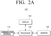
- the display 120 may display video content received from the user terminal device 200 based on a control by the processor 140. Further, the display 120 may display an audio UI that is different than a UI that is concurrently being displayed via the user terminal device 200 based on a control by the processor 140.
- the memory 130 may store information associated with the user terminal device 200, and information associated with content that is received from the user terminal device 200.
- the memory 130 may store information associated with the user terminal device 200, such as an Internet protocol (IP) address of the user terminal device 200, a network environment, security settings, and connection history.
- IP Internet protocol
- the memory 130 may store a title, a type, a history, and the like, of the content received form the user terminal device 200.
- the processor 140 may switch a mode of the display device 100 from the standby mode to the normal mode. Then, the processor 140 may control the display 120 to display the video content and the indicator indicating that the information associated with the video content was received, based on the information associated with the video content that is received from the user terminal device 200, in the normal mode.
- the indicator indicating that the information regarding the video content was received may be an indicator having a play button shape as shown in FIG. 1A . Alternatively, the indicator indicating that the information regarding the video content was received may also be a thumbnail icon of the received video content.
- the processor 140 may control an audio output component 170 to output the audio content based on the information associated with the audio content, and may control the display 120 to display, on the standby screen, an audio UI that is different from a UI that is concurrently being displayed on the user terminal device 200.
- the processor 140 may identify an audio UI based on information (e.g., a title of the audio content, a playback point, a playlist, or the like) associated with audio content that is received from the user terminal device 200, and control the display 120 to display the identified audio UI.
- the processor 140 may store information (e.g., an IP address of the user terminal device 200, a network environment, security settings, and user information of the user terminal device 200) associated with the user terminal device 200 that is received from the user terminal device 200, a type and a history of content received from the user terminal device 200, in the memory 130. Further, the processor 140 may control the display 120 to display the indicator indicating that the user terminal device 200 is within communicative proximity, based on the stored information associated with the user terminal device 200. Further, the processor 140 may control the display 120 to display a UI including the stored type and history of content received from the user terminal device 200 on the standby screen or a screen in the normal mode.
- information e.g., an IP address of the user terminal device 200, a network environment, security settings, and user information of the user terminal device 200
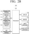
- the Bluetooth module 112 may be a module that is configured to connect to the user terminal device 200 using a Bluetooth low energy (BLE) protocol.
- Bluetooth is a wireless communication method using an industrial, scientific, and medical (ISM) frequency range (e.g., 2402 to 2480 MHz).
- ISM industrial, scientific, and medical
- the Bluetooth module 112 may receive, from the user terminal device 200, information associated with audio content output via the user terminal device 200 by using Bluetooth communication .
- the P2P module 114 may be a module that is configured to connect to the user terminal device 200 by using P2P communication. According to an embodiment, the P2P module 114 may connect to the user terminal device 200 by utilizing Wi-Fi Direct, which is a Wi-Fi-based P2P standard, without requiring access to separate equipment such as an access point (AP) or a router. Further, the P2P module 114 may receive, form the user terminal device 200, information associated with video content that is being output via the user terminal device 200.
- Wi-Fi Direct is a Wi-Fi-based P2P standard
- the input component 160 may receive a user input for controlling the display device 100.
- the input component 160 may include, for example, a touch panel for receiving a touch gesture, a stylus pen, or the like, and a button for receiving a manipulation by the user.
- the input component 160 may be implemented by another input device (e.g., a remote controller 800, a virtual keyboard, a mouse, a motion input component, or the like).
- the processor 140 may include one or more of a central processing unit (CPU) configured to process a digital signal, a microcontroller unit (MCU), a micro processing unit (MPU), a controller, an application processor (AP), a communication processor (CP), an ARM processor, or the like.
- the processor 140 may be implemented by a system-on-chip (SoC) or a large scale integration (LSI) in which a processing algorithm is embedded, or may be implemented in a field programmable gate array (FPGA) form.
- SoC system-on-chip
- LSI large scale integration
- FPGA field programmable gate array
- the processor 140 may perform various functions by executing computer executable instructions stored in the memory 130.
- the processor 140 may include at least one of a graphics processing unit (GPU), a neural processing unit (NPU), or a visual processing unit (VPU) as a separate artificial intelligence (AI) dedicated processor configured to perform an Al function.
- GPU graphics processing unit
- NPU neural processing unit
- VPU visual processing
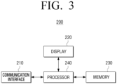
- FIG. 3 is a block diagram schematically illustrating a configuration of the user terminal device 200 according to an embodiment of the disclosure.
- the communication interface 210 may include at least one of a Wi-Fi chip, a Bluetooth chip, a P2P chip, or a wireless communication chip.
- the Wi-Fi chip, the Bluetooth chip, and the P2P chip may perform Wi-Fi communication, Bluetooth communication, and P2P communication, respectively.
- the wireless communication chip may be a chip configured to perform communication according to various communication protocols such as Institute of Electrical and Electronics Engineers (IEEE), Zigbee, 3rd generation (3G), 3rd generation partnership project (3GPP), long term evolution (LTE), 5th generation (5G), and the like.
- IEEE Institute of Electrical and Electronics Engineers
- the communication interface 210 may transmit information associated with audio content to the display device 100 by using Bluetooth communication, and transmit information associated with video content to the display device 100 by using P2P communication.
- the communication interface 210 may transmit content by using various communication methods.
- the memory 230 may include at least one instruction related to the user terminal device 200.
- the memory 230 may include a semiconductor memory such as a flash memory, or a magnetic storage medium such as a hard disk, or the like. Further, the memory 230 may store various kinds of information such as various kinds of data input, set, or generated during execution of the programs or the applications therein.
- the memory 230 may store the information associated with the display device 100 and connection information.
- the processor 240 may identify a type of the content that is currently being output via the user terminal device 200. Specifically, the processor 240 may analyze metadata of content that is being output, or the like to identify the type of content. Further, the processor 240 may control the communication interface 210 to transmit information associated with the content that is being output via the user terminal device 200 to the display device 100 by using different communication methods according to the identified type of content.
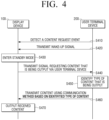
- FIG. 4 is a sequence diagram illustrating a process in which the display device outputs content that is being output via the user terminal device, according to an embodiment.
- the display device 100 may detect a content request event associated with a request for the display device 100 to output information associated with content that is being output via the user terminal device 200 (S410).
- the content request event may be an event in which the user terminal device 200 is brought within communicative proximity of the NFC tag including information (e.g., a MAC address of the display device) and connection information.
- the user terminal device 200 may receive the information associated with the display device 100 that is stored in the NFC tag, and transmit the wake-up signal to the display device 100 (S420).
- the display device 100 may enter the standby mode in which the predetermined standby screen is provided, even when the display device 100 is powered off (S430). Specifically, based on entering the standby mode, the display device 100 may display, on a region corresponding to a position where the user terminal device 200 is within communicative proximity, the indicator indicating that the user terminal device is within communicative proximity.
- the display device 100 may transmit, to the user terminal device 200, the signal for requesting information associated with content that is being output via the user terminal device 200 (S440). Based on receiving the signal for requesting information associated with content that is being output via the user terminal device 200, the user terminal device 200 may identify a type of the content that is being output (S450). Specifically, the user terminal device 200 may analyze metadata of the content that is being output to identify whether the type of content is audio data or video data.
- the user terminal device 200 may transmit the information associated with the content by using different communication methods based on the identified type of content (S460). Specifically, the user terminal device 200 may utilize connection information received from the display device 100 when transmitting the information associated with the content by using the different communication methods. According to an embodiment, and in a case where the content is identified as audio content, the user terminal device 200 may transmit information associated with the audio content to the display device 100 by using Bluetooth communication. Further, and in a case where the content is identified as video content, the user terminal device 200 may transmit information regarding the video content to the display device 100 by using P2P communication.
- the display device 100 may output the content in a manner according to the type of content, based on the received information regarding the content (S470). Specifically, in a case where the content that is being output via the user terminal device 200 is audio content, the display device 100 may display an audio UI that is different than a UI that is concurrently being displayed on the user terminal device 200 while outputting the audio content, based on received information associated with the audio content. alternatively, and in a case where the content that is being output via the user terminal device 200 is video content, the display device 100 may be switched from the standby mode to the normal mode, and display the video content and the indicator indicating that information associated with the video content is received, based on the received information associated with the video content.
- FIGS. 5A to 5C are views for describing a process in which the display device 100 receives information associated with video content from the user terminal device 200, and outputs content based on the received information according to an embodiment.
- the display device 100 may be in a powered-off state. A function to be described later may be performed even in a state in which the display device 100 is powered off.
- the display device 100 may receive the wake-up signal from the user terminal device 200 and enter the standby mode in which the predetermined standby screen 30 is provided.
- the display device 100 may display, on a region of the standby screen 30, indicators 50 and 60 indicating that the user terminal device 200 is within communicative proximity of the display device 100.
- the region may correspond to a position where the user terminal device 200 is within communicative proximity.
- the display device 100 may display the indicator 50 indicating that the user terminal device 200 is within communicative proximity, on a right-upper side region of the display 120.
- the display device 100 may receive information (e.g., an IP address, received content history, user information, security settings, a network environment, and the like, of the user terminal device 200) associated with the user terminal device 200. Therefore, the display device 100 may display, on the standby screen 30, a UI 70-1 indicating that the user terminal device 200 is within communicative proximity, based on the received information.
- information e.g., an IP address, received content history, user information, security settings, a network environment, and the like
- the display device 100 may display, on the standby screen 30, the UI 70-1 that displays a phrase "Hello, Chulsoo.” Further, the display device 100 may display, on the standby screen 30, a UI 70-2 that displays weather and calendar information or a UI 70-3 that displays latest content information, but this is merely an embodiment, and the display device 100 may display a UI displaying various types of information.
- the display device 100 may transmit, to the user terminal device 200, a signal that requests the user terminal device 200 for information associated with content.
- the user terminal device 200 may identify that video content is being output, and transmit information associated with the video content to the display device 100 by using P2P communication.
- the display device 100 may be switched from the standby mode to the normal mode, and display video content 10, and the indicator 20 indicating that video content is received, based on the information associated with the video content that is received from the user terminal device 200.
- the display device 100 may display the indicator 20 indicating that video content is received for a predetermined time frame and then remove the indicator 20.
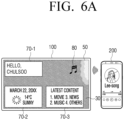
- FIGS. 6A and 6B are views for describing a process in which the display device 100 receives information associated with audio content from the user terminal device 200, and outputs the audio content based on the received information associated with the audio content, according to an embodiment.
- FIGS. 6A and 6B illustrate a similar situation as that shown in FIGS. 5A to 5C except that audio content is output instead of video content.
- the display device 100 may display indicators 50 and 80 indicating that the user terminal device 200 is within communicative proximity, on a region of the standby screen 30.
- the region may correspond to a position where the user terminal device 200 is within communicative proximity.
- the user terminal device 200 outputs audio content, and thus the indicator 80 indicating that the user terminal device 200 is within communicative proximity may have a musical note shape corresponding to audio content. It should be understood that this is merely an embodiment, and the indicator 80 indicating that the user terminal device 200 is within communicative proximity may be implemented in various forms. Further, as shown in FIG.
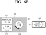
- the user terminal device 200 may identify that audio content is being output, and transmit information associated with the audio content to the display device 100 by using Bluetooth communication.
- the display device 100 may display, on the standby screen 30, the audio Uls 40-1, 40-2, and 40-3 that are different than a UI that is being concurrently displayed via the user terminal device 200, and output the audio content based on the received information associated with the audio content. Further, the display device 100 may display, on the standby screen 30, the audio Uls 40-1, 40-2, and 40-3 that are generated based on the received information (e.g., a title of the audio content, image information related to the audio content, a play history, a playback point, and a playlist) associated with the audio content that is received from the user terminal device 200.
- the received information e.g., a title of the audio content, image information related to the audio content, a play history, a playback point, and a playlist
- the display device 100 may display the audio UI 40-1, the audio UI 40-2, and the audio UI 40-3 on the standby screen 30.
- the audio UI 40-1 may be generated based on information associated with the title of the audio content and the playback point
- the audio UI 40-2 may be generated based on information regarding an image relevant to the received audio content
- the playback point and the audio UI 40-3 may be generated based on received information associated with the play history.
- this is merely an embodiment, and the display device 100 may display, on the standby screen 30, various Uls generated based on information regarding an audio content.
- FIG. 7 is a view for describing a process in which the display device 100 receives information associated with content from the external server 700 and the user terminal device 200 according to an embodiment.
- the display device 100 may receive information associated with the video content from the user terminal device 200.
- the information may include a title and a current playback point of the video content that is currently being output via the user terminal device 200.
- the display device 100 may receive, from the user terminal device 200, information indicating that a title of the video content that is being output via the user terminal device 200 is "hiking," and information identifying that a current playback point of the video content is 59 minutes.
- the display device 100 may receive, from the external server 700 from which the user terminal device 200 also receives the video content, a portion of the video content that corresponds to the current playback point of the video content that is being output via the user terminal device 200, based on the received information.
- the display device 100 may receive, from the external server 700, video content titled "hiking" after the playback point of 59 minutes. Therefore, the display device 100 may receive and display the video content that corresponds to the current playback point of the video content that is received from the external server 700 and is being output via the user terminal device 200.
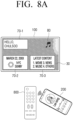
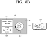
- FIGS. 8A and 8B are views for describing a process in which the user terminal device 200 is brought within communicative proximity of the external device 800 connected to the display device 100, according to an embodiment.
- the external device 800 is implemented by a remote controller, but this is merely an embodiment, and the external device 800 may be implemented by various devices such as an Al speaker.
- the external device 800 may include an NFC tag in which information (e.g., a MAC address of the display device 100) associated with the display device 100 and connection information are stored.
- the user terminal device 200 or the external device 800 may transmit the wake-up signal to the display device 100.
- the display device 100 may enter the standby mode in which the predetermined standby screen 30 is provided.
- the display device 100 may display, on the standby screen 30, the indicator 80 indicating that the user terminal device 200 is within communicative proximity of the external device 800, the UI 70-1 including information associated with the user terminal device 200 that is received from the user terminal device 200, and the Uls 70-2 and 70-3 indicating weather and calendar information and latest content, respectively.
- the display device 100 may display a UI including various types of information, on the standby screen 30.
- the display device 100 may transmit, to the user terminal device 200, the signal that requests information associated with content that is being output via the user terminal device 200. That is, as similar to the case where the user terminal device 200 is directly brought within communicative proximity of the display device 100, the display device 100 may transmit the signal that requests information associated with content that is being output via the user terminal device 200 even in a case where the user terminal device 200 is within communicative proximity of the external device 800 connected to the display device 100.
- the user terminal device 200 outputs audio content, and thus the user terminal device 200 may transmit information associated with the audio content to the display device 100 by using Bluetooth communication.
- a subsequent process has been described above with reference to FIG. 6B , and thus a redundant description may be omitted.
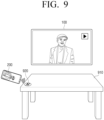
- FIGS. 9 through 11 are views for describing a process in which the user terminal device 200 is brought within communicative proximity of an NFC tag external to the display device 100, according to an embodiment.
- the NFC tag including information (e.g., a MAC address of the display device 100) associated with the display device 100, and connection information (e.g., a Bluetooth MAC address and a P2P device MAC address) may be external to the display device 100. That is, the NFC tag may be disposed externally to the display device 100, and the embodiments shown in FIGS. 9 through 11 are merely embodiments.
- an NFC tag 920 may be disposed on a table 910 as shown in FIG. 9 . Based on the user terminal device 200 being brought within communicative proximity of the NFC tag 920, the user terminal device 200 may receive, from the NFC tag 920, information associated with the display device 100 and connection information via NFC with the NFC tag 920. Further, the user terminal device 200 may connect to the display device 100 based on the received information.
- the display device 100 may transmit, to the user terminal device 200, the signal that requests information associated with content that is currently being output via the user terminal device 200. Based on receiving the signal that requests the information associated with content, the user terminal device 200 may identify a type of the content that is currently being output, and transmit, to the display device 100, information associated with the content that is being output by using different communication methods according to the identified type of content. Referring to FIG. 9 , based on video content being output via the user terminal device 200, the user terminal device 200 may transmit, to the display device 100, information associated with the video content by using P2P communication. Further, the display device 100 may display the video content and the indicator indicating that the video content is received, based on the received information associated with the video content. A detailed description of the screen on which the video content is output has been provided above with reference to FIGS. 5B and 5C , and thus redundant description may be omitted.
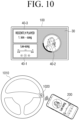
- an NFC tag 1020 may be disposed on a vehicle handle 1010 as shown in FIG. 10 .
- the user terminal device 200 may receive, from the NFC tag 1020, information associated with the display device 100 and connection information via NFC with the NFC tag 1020. Further, the user terminal device 200 may connect to the display device 100 based on the received information.
- the display device 100 may transmit, to the user terminal device 200, the signal that requests transmission of information associated with content that is being output via the user terminal device 200.
- the user terminal device 200 may identify a type of the content that is currently being output, and transmit, to the display device 100, information associated with the content that is being output by using different communication methods according to the identified type of content. Referring to FIG.
- the user terminal device 200 may transmit, to the display device 100, information associated with the audio content by using Bluetooth communication. Then, the display device 100 may output the audio content based on the received information associated with the audio content and display, on the standby screen 30, the audio Uls 40-1, 40-2, and 40-3 that are different than the UI that is concurrently displayed via the user terminal device 200.
- a detailed description of the standby screen 30 and the audio Uls 40-1, 40-2, and 40-3 has been provided above with reference to FIGS. 6A and 6B , and thus redundant description may be omitted.
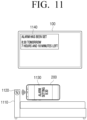
- an NFC tag 1120 may be disposed on a bed 1110 as shown in FIG. 11 .
- the NFC tag 1120 may include a control instruction for executing a specific application, in addition to information associated with the display device 100 and connection information. Specifically, based on the user terminal device 200 being brought within communicative proximity of the NFC tag 1120, the user terminal device 200 may receive, from the NFC tag 1120, information associated with the display device 100, connection information, and a control instruction for executing an alarm application. The user terminal device 200 may connect to the display device 100 based on the information received from the NFC tag 1120 via NFC, and execute an alarm application 1130.
- the user terminal device 200 may transmit a signal including the input instruction to the display device 100. Further, the display device 100 may display a notification UI 1140 that is generated based on the received signal and set alarm.
- a user instruction e.g., an instruction to set an alarm for 8:30 as shown in FIG. 11
- the user terminal device 200 may transmit a signal including the input instruction to the display device 100. Further, the display device 100 may display a notification UI 1140 that is generated based on the received signal and set alarm.
- FIG. 11 illustrates a case where the NFC tag 1120 includes the control instruction for executing the alarm application, but this is merely an embodiment, and the NFC tag 1120 may include various control instructions.
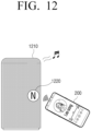
- FIG. 12 is a view for describing a case where the display device 100 is implemented by an Al speaker 1210, according to an embodiment.
- An NFC tag 1220 illustrated in FIG. 12 may include information (e.g., a MAC address of the Al speaker) associated with the Al speaker 1210, and connection information (e.g., a Bluetooth MAC address and a P2P device MAC address).
- the NFC tag 1220 may be embedded in the Al speaker 1210 or disposed on an outer portion of the Al speaker 1210.
- the user terminal device 200 may receive, from the NFC tag 1220, information associated with the Al speaker 1210 and connection information via NFC.
- the Al speaker 1210 may transmit, to the user terminal device 200, the signal that requests information associated with content that is currently being output via the user terminal device 200.
- the user terminal device 200 may identify a type of the content that is being output, and transmit, to the Al speaker 1210, information associated with the content by using different communication methods according to the identified type of content.
- the user terminal device 200 may transmit information associated with the audio content to the AI speaker 1210 by using Bluetooth communication.
- the Al speaker 1210 may output the audio content based on the received information associated with the audio content.
- the user terminal device 200 may transmit the wake-up signal to the Al speaker 1210. Based on receiving the wake-up signal, the Al speaker 1210 may be powered on to output the received content.
- the Al speaker 1210 may not include the NFC tag 1220.
- the Al speaker 1210 may transmit, to the user terminal device 200, the signal that requests transmission of information associated with content that is currently being output via the user terminal device 200.
- the content request event may be an event in which the user terminal device 200 transmits, to the Al speaker 1210, a signal that induces transmission of the signal that requests information associated with content that is currently being output.
- FIG. 12 illustrates a case where the display device 100 is implemented by an Al speaker 1210, but this is merely an embodiment, and the display device 100 may be implemented by various electronic devices such as a PC.
- FIGS. 13A through 13C are views for describing processes in which a connection between the display device 100 and the user terminal device 200 is terminated according to an embodiment.
- the connection between the display device 100 and the user terminal device 200 may be ended. That is, based on the user terminal device 200 being brought within communicative proximity of the NFC tag of the display device 100 in a state in which the connection between the display device 100 and the user terminal device 200 is established, the connection may be ended. Put another way, the user of the user terminal device 200 may perform a first NFC tap to establish the connection, and perform a second NFC tap to end the connection.
- the display device 100 may display a UI 1310 indicating that the connection is ended.
- the UI 1310 indicating that communicative connection is ended may be a UI including a message "connection with Chulsoo has been ended" as shown in FIG. 13A , but this is merely an embodiment, and the UI 1310 may be implemented in various forms.
- the connection may be ended. Specifically, based on a distance between the user terminal device 200 and the display device 100 exceeding the threshold distance, the user terminal device 200 may transmit, to the display device 100, a signal that ends the connection. Based on receiving the signal that ends the connection, the display device 100 may end the connection with the user terminal device 200, and display the UI 1310 indicating that connection is ended.
- the established connection may be ended. That is, based on another user terminal device 200-1 being brought within communicative proximity of the display device 100, the display device 100 may end the established connection with the user terminal device 200, and display the UI 1310 indicating that connection is ended. Further, the display device 100 may transmit, to the terminal device 200-1 that is more recently brought within communicative proximity, the signal that requests information associated with content that is currently being output.
- FIG. 14 is a view for describing a UI 1410 for selecting information associated with content to be transmitted from the user terminal device 200 to the display device 100 according to an embodiment.
- the user terminal device 200 may display the UI 1410 for selecting information associated with content to be transmitted to the display device 100.
- the UI 1410 for selecting information associated with content may include Uls 1420, 1430, and 1440 indicating content to be transmitted.
- the UI 1420 corresponding to audio content may have a musical note shape as shown in FIG. 14 , but this is merely an embodiment, and the UI 1420 may be a UI including metadata of audio content.
- the UI 1430 corresponding to video content may have a play button shape as shown in FIG.
- the UI 1430 may be a thumbnail icon of the video content or a UI including a title of the content, or the like.
- the UI 1440 corresponding to a uniform resource locator (URL) may be a UI in which a word "URL" is written as shown in FIG. 14 , or may be a UI including a name of a website accessible via the URL, or control information for installing an application.
- URL uniform resource locator
- the user terminal device 200 may transmit the selected information associated with content to the display device 100. Particularly, the user terminal device 200 may transmit the information associated with content to the display device 100 by using different communication methods according to a type of selected information associated with content. Further, the user terminal device 200 may utilize connection information (e.g., a Bluetooth MAC address and a P2P device MAC address) received from the display device 100 to transmit the information associated with content to the display device 100 by using different communication methods according to the type of selected content. According to an embodiment, based on the selected content being audio content, the user terminal device 200 may transmit information associated with the audio content to the display device 100 by using Bluetooth communication. Further, based on the selected content being video content, the user terminal device 200 may transmit information associated with the video content to the display device 100 by using P2P communication.
- connection information e.g., a Bluetooth MAC address and a P2P device MAC address
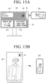
- FIGS. 15A and 15B are views for describing a process in which the display device 100 determines whether to rotate the display 120 according to an embodiment.
- the display device 100 may receive the wake-up signal from the user terminal device 200, and enter the standby mode in which the predetermined standby screen 30 is provided.
- a description of entering the standby mode has been provided above with reference to FIG. 5B , and thus a redundant description may be omitted.
- the display device 100 may determine whether to rotate the display 120 based on information associated with video content that includes information identifying orientation information of the video content received from the user terminal device 200. Specifically, the display device 100 may identify whether an orientation of the display 120 and an orientation of the video content are different from each other based on the information received from the user terminal device 200. Based on identifying that the orientation of the display 120 and the orientation of the video content are different from each other, the display device 100 may determine to rotate the display 120. According to an embodiment, and as shown in FIG.
- the display device 100 may identify that the orientation of the display 120 and the orientation of the video content are different from each other. Further, the display device 100 may determine to rotate the display 120 into the portrait orientation, and rotate the display 120 into the determined orientation.
- the display device 100 may identify that the orientation of the display 120 and the orientation of the video content are different from each other. Further, the display device 100 may determine to rotate the display 120 into the landscape orientation, and rotate the display 120 into the determined orientation.
- the display device 100 may rotate the display 120 based on the information indicating that orientation information of video content is changed being received from the user terminal device 200.
- the display device 100 may rotate the display 120 into the portrait orientation from the landscape orientation.
- FIG. 16 is a flowchart for describing a method for controlling the display device 100 according to an embodiment.
- the display device 100 may request the user terminal device 200 for information associated with content that is being output via the user terminal device 200 (S1610).
- the content request event may be an event in which the user terminal device 200 is brought within communicative proximity of an NFC tag in which information associated with the display device 100 is stored. That is, a user of the user terminal device 200 may perform an NFC tap using the user terminal device 200. Put another way, the user may "tag" the user terminal device 200 to the NFC tag.
- the display device 100 may receive the wake-up signal from the user terminal device 200. Based on receiving the wake-up signal, the display device 100 may enter the standby mode in which the predetermined standby screen is provided. Further, the display device 100 may display the indicator indicating that the user terminal device 200 is within communicative proximity (e.g., that an NFC tap or tag has been performed), on a region of the standby screen that corresponds to a position where the user terminal device 200 is within communicative proximity (e.g., where the NFC tap or tag was performed).
- communicative proximity e.g., that an NFC tap or tag has been performed
- the display device 100 may identify a type of the received content (S1620). According to an embodiment, based on determining that the received content is video content, the display device 100 may display the video content based on the received information associated with the video content (S1630). Specifically, in a case where information associated with video content is received, the display device 100 may be switched from the standby mode to the normal mode, and display the video content and the indicator indicating that the video content is received based on the information associated with the video content.
- the display device 100 may display an audio UI that is different from a UI that is concurrently being displayed via the user terminal device 200, and output the audio content based on the received information associated with the audio content (S1640). Specifically, the display device 100 may generate the audio UI based on the received information associated with the audio content. Further, the display device 100 may output the audio content based on the information associated with the audio content, and display the audio UI on the standby screen.
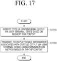
- FIG. 17 is a flowchart for describing a method for controlling the user terminal device 200 according to an embodiment.
- the user terminal device 200 may identify a type of the content that is currently being output via the user terminal device 200. Specifically, the user terminal device 200 may analyze metadata of the content that is currently being output to identify whether the content is audio content or video content (S1710).
- the user terminal device 200 may transmit information associated with content that is being output via the user terminal device 200 to the display device 100 by using different communication methods based on the identified type of content (S1720). Specifically, in a case where the content that is being output is identified as audio content, the user terminal device 200 may transmit information associated with the audio content to the display device 100 by using Bluetooth communication. In a case where the content that is being played is identified as video content, the user terminal device 200 may transmit information associated with the video content to the display device 100 by using P2P communication.
- module or a “[function]er/or” may denote a unit implemented in hardware, software, or firmware, and may be used interchangeably with a term such as logic, a logic block, a part, or a circuit.
- the terms "[function]er/or” or “module” may indicate an integrated part, or a minimum unit for performing one or more functions, or part thereof.
- a module may be implemented by an ASIC.
- Various embodiments of the disclosure may be implemented by software including instructions stored in a machine-readable storage medium (e.g., a non-transitory computer-readable medium).
- a machine may be a device that invokes the stored instruction from the storage medium and may be operated depending on the invoked instruction, and may include an electronic device (e.g., the display device 100) according to the disclosed embodiments.
- the processor may directly perform a function corresponding to the instruction or other components may perform the function corresponding to the instruction under a control of the processor.
- the instruction may include code created or executed by a compiler or an interpreter.
- the machine-readable storage medium may be provided in a form of a non-transitory storage medium.
- the term "non-transitory" may mean that the storage medium is tangible, and might not distinguish whether data is semi-permanently or temporarily stored on the storage medium.
- the methods according to the embodiments may be included and provided in a computer program product.
- the computer program product may be traded as a product between a seller and a purchaser.
- the computer program product may be distributed in a form of a storage medium (e.g., a compact disc read only memory (CD-ROM)) that may be read by the machine or online through an application store (e.g., PlayStoreTM).
- an application store e.g., PlayStoreTM
- at least portions of the computer program product may be at least temporarily stored in a storage medium such as a memory of a server of a manufacturer, a server of an application store, or a relay server or be temporarily created.
- each of components may include a single entity or a plurality of entities, and some of the corresponding sub-components described above may be omitted or other sub-components may be further included in the embodiments.
- some of the components e.g., the modules or the programs
- Operations performed by the modules, the programs, or other components according to the embodiments may be executed in a sequential manner, a parallel manner, an iterative manner, or a heuristic manner, at least some of the operations may be performed in a different order or be omitted, or other operations may be added.
Landscapes
- Engineering & Computer Science (AREA)
- Theoretical Computer Science (AREA)
- Multimedia (AREA)
- General Physics & Mathematics (AREA)
- Human Computer Interaction (AREA)
- Physics & Mathematics (AREA)
- General Engineering & Computer Science (AREA)
- Signal Processing (AREA)
- General Health & Medical Sciences (AREA)
- Audiology, Speech & Language Pathology (AREA)
- Health & Medical Sciences (AREA)
- Computer Networks & Wireless Communication (AREA)
- Two-Way Televisions, Distribution Of Moving Picture Or The Like (AREA)
- Controls And Circuits For Display Device (AREA)
- Selective Calling Equipment (AREA)
- Telephone Function (AREA)
- User Interface Of Digital Computer (AREA)
Claims (11)
- Anzeigegerät (100) umfassend:eine Kommunikationsschnittstelle (110), die konfiguriert ist, um mit einem Benutzerendgerät (200) zu kommunizieren;eine Anzeige (120);einen Speicher (130), der konfiguriert ist, um mindestens eine Anweisung zu speichern; undeinen Prozessor (140), der konfiguriert ist, um die mindestens eine Anweisung auszuführen, um:als Reaktion auf das Erkennen eines Inhaltsanforderungsereignisses, das mit einer Anforderung an das Anzeigegerät verknüpft ist, Informationen auszugeben, die mit Inhalten verknüpft sind, die über das Benutzerendgerät ausgegeben werden, die mit den Inhalten verknüpften Informationen über die Kommunikationsschnittstelle vom Benutzerendgerät zu empfangen;basierend auf der Art des Inhalts, der über das Benutzerendgerät ausgegeben wird und bei dem es sich um Videoinhalt handelt, die Anzeige so steuern, dass der Videoinhalt basierend auf mit dem Videoinhalt verknüpften Informationen angezeigt wird, die vom Benutzerendgerät empfangen werden; undbasierend auf der Art des Inhalts, der über das Benutzerendgerät ausgegeben wird und Audioinhalt ist, die Anzeige zu steuern, um eine Audio-Benutzeroberfläche (UI) anzuzeigen, die sich von einer UI unterscheidet, die gleichzeitig über das Benutzerendgerät angezeigt wird, und das Anzeigegerät zu steuern, um den Audioinhalt auszugeben, basierend auf mit dem Audioinhalt verknüpften Informationen, die vom Benutzerendgerät empfangen werden;wobei der Prozessor ferner dazu konfiguriert ist, mindestens eine Anweisung auszuführen, um:
aufgrund der Bewegung des Benutzerendgeräts in kommunikativer Nähe eines NFC-Tags des Anzeigegeräts in einem Zustand, in dem eine Verbindung zwischen dem Anzeigegerät und dem Benutzerendgerät hergestellt ist, die Verbindung zwischen dem Anzeigegerät und dem Benutzerendgerät zu beenden. - Anzeigegerät (100) nach Anspruch 1, weiterhin umfassend:eine Near-Field-Communication-(NFC)-Schnittstelle (150) mit dem NFC-Tag, das mit dem Anzeigegerät verbundene Informationen und Verbindungsinformationen speichert,wobei das Inhaltsanforderungsereignis ein Ereignis ist, bei dem das Benutzerendgerät in kommunikative Nähe des NFC-Tags des Anzeigegeräts gebracht wird, unddie Verbindungsinformationen Informationen umfassen, die mit einer Verbindungsmethode verbunden sind, durch die die mit dem über das Benutzerendgerät ausgegebenen Inhalt verbundenen Informationen empfangen werden können.
- Anzeigegerät (100) nach Anspruch 2, wobei der Prozessor (140) dazu konfiguriert ist:ein Wecksignal über die NFC-Schnittstelle (150) zu empfangen und in einen Standby-Modus zu wechseln, in dem ein vorgegebener Standby-Bildschirm über die Anzeige (120) angezeigt wird, basierend darauf, dass das Benutzerendgerät (200) in kommunikative Nähe des Anzeigegeräts gebracht wird, während das Anzeigegerät ausgeschaltet ist; unddie Anzeige so zu steuern, dass die Audio-Benutzeroberfläche über den Standby-Bildschirm angezeigt wird, basierend auf dem Audioinhalt, der vom Benutzerendgerät empfangen wird.
- Anzeigegerät (100) nach Anspruch 3, wobei der Prozessor (140) dazu konfiguriert ist:
die Anzeige (120) so zu steuern, dass es einen Indikator anzeigt, der angibt, dass sich das Benutzerendgerät (200) in kommunikativer Nähe des Anzeigegeräts befindet, und zwar in einem Bereich, der einer Position entspricht, an der sich das Benutzerendgerät in kommunikativer Nähe des Anzeigegeräts befindet, basierend auf dem Eintritt in den Standby-Modus. - Anzeigegerät (100) nach Anspruch 3, wobei der Prozessor (140) dazu konfiguriert ist:basierend auf dem über das Benutzerendgerät (200) ausgegebenen Inhalt, der Videoinhalt ist, einen Modus des Anzeigegeräts vom Standby-Modus in einen Normalmodus umzuschalten; unddie Anzeige (120) so zu steuern, dass es den Videoinhalt und einen Indikator anzeigt, der angibt, dass die mit dem Videoinhalt verknüpften Informationen vom Benutzerendgerät empfangen werden.
- Anzeigegerät (100) nach Anspruch 1, wobei der Prozessor (140) dazu konfiguriert ist:basierend auf dem über das Benutzerendgerät (200) ausgegebenen Inhalt, der Videoinhalt ist, der von einem externen Server (700) empfangen wurde, über die Kommunikationsschnittstelle einen Teil des Videoinhalts vom externen Server zu empfangen, der einem aktuellen Wiedergabepunkt des über das Benutzerendgerät ausgegebenen Videoinhalts entspricht; unddie Anzeige zu steuern, um den Teil des Videoinhalts basierend auf den mit dem Videoinhalt verknüpften Informationen anzuzeigen (120), die Informationen umfassen, die einen Titel des Videoinhalts identifizieren, und den aktuellen Wiedergabepunkt des Videoinhalts, der über das Benutzerendgerät ausgegeben wird.
- Anzeigegerät (100) nach Anspruch 1, wobei das Inhaltsanforderungsereignis ein Ereignis ist, bei dem das Benutzerendgerät (200) in Kommunikationsnähe zu einem externen Gerät (800) gebracht wird, das mit dem Anzeigegerät verbunden ist.
- Verfahren zum Steuern eines Anzeigegeräts (100), wobei das Verfahren Folgendes umfasst:Empfangen der mit dem Inhalt verbundenen Informationen vom Benutzerendgerät, als Reaktion auf das Erkennen eines Inhaltsanforderungsereignisses, das mit einer Anforderung an das Anzeigegerät verknüpft ist, Informationen auszugeben, die mit Inhalt verknüpft sind, der über ein Benutzerendgerät (200) ausgegeben wird;Anzeigen der mit dem Inhalt verknüpften Informationen vom Benutzerendgerät, basierend darauf, dass der über das Benutzerendgerät ausgegebene Inhalt Videoinhalt ist, wobei der Videoinhalt auf mit dem Videoinhalt verknüpften Informationen basiert, die vom Benutzerendgerät empfangen werden;Anzeigen einer Audiobenutzerschnittstelle (UI), basierend darauf, dass der über das Benutzerendgerät ausgegebene Inhalt Audioinhalt ist, die sich von einer UI unterscheidet, die gleichzeitig über das Benutzerendgerät angezeigt wird, und Ausgeben des Audioinhalts auf der Grundlage von mit dem Audioinhalt verknüpften Informationen, die vom Benutzerendgerät empfangen werden; undbasierend darauf, dass das Benutzerendgerät in kommunikativer Nähe eines NFC-Tags des Anzeigegeräts bewegt wird, in einem Zustand, in dem eine Verbindung zwischen dem Anzeigegerät und dem Benutzerendgerät hergestellt ist, wird die Verbindung zwischen dem Anzeigegerät und dem Benutzerendgerät beendet.
- Verfahren nach Anspruch 8, wobei das Inhaltsanforderungsereignis ein Ereignis ist, bei dem das Benutzerendgerät (200) in kommunikative Nähe des Near-Field-Communication-(NFC)-Tags des Anzeigegeräts (100) gebracht wird.
- Verfahren nach Anspruch 9, wobei das Anzeigen der Audio-UI Folgendes umfasst:Empfangen eines Wecksignals und Eintreten in einen Standby-Modus, in dem ein vorgegebener Standby-Bildschirm bereitgestellt wird, basierend darauf, dass das Benutzerendgerät (200) in kommunikative Nähe des Anzeigegeräts (100) gebracht wird, während sich das Anzeigegerät in einem ausgeschalteten Zustand befindet; undAnzeigen der Audio-UI über den Standby-Bildschirm basierend auf dem Audioinhalt, der vom Benutzerendgerät empfangen wird.
- Verfahren nach Anspruch 10, wobei das Eintreten in den Standby-Modus das Anzeigen eines Indikators umfasst, der angibt, dass sich das Benutzerendgerät (200) in kommunikativer Nähe des Anzeigegeräts (100) befindet, und zwar in einem Bereich, der einer Position entspricht, an der sich das Benutzerendgerät in kommunikativer Nähe des Anzeigegeräts befindet, basierend auf dem Eintreten in den Standby-Modus.
Priority Applications (1)
| Application Number | Priority Date | Filing Date | Title |
|---|---|---|---|
| EP25155822.7A EP4529193A3 (de) | 2019-04-18 | 2019-09-30 | Anzeigevorrichtung, benutzerendgerätevorrichtung, verfahren zur steuerung der anzeigevorrichtung und verfahren zur steuerung einer benutzerendgerätevorrichtung |
Applications Claiming Priority (2)
| Application Number | Priority Date | Filing Date | Title |
|---|---|---|---|
| KR20190045703 | 2019-04-18 | ||
| KR1020190111452A KR102339367B1 (ko) | 2019-04-18 | 2019-09-09 | 디스플레이 장치, 사용자 단말 장치 및 디스플레이 장치와 사용자 단말 장치 의 제어 방법 |
Related Child Applications (1)
| Application Number | Title | Priority Date | Filing Date |
|---|---|---|---|
| EP25155822.7A Division EP4529193A3 (de) | 2019-04-18 | 2019-09-30 | Anzeigevorrichtung, benutzerendgerätevorrichtung, verfahren zur steuerung der anzeigevorrichtung und verfahren zur steuerung einer benutzerendgerätevorrichtung |
Publications (3)
| Publication Number | Publication Date |
|---|---|
| EP3726367A1 EP3726367A1 (de) | 2020-10-21 |
| EP3726367C0 EP3726367C0 (de) | 2025-02-05 |
| EP3726367B1 true EP3726367B1 (de) | 2025-02-05 |
Family
ID=68104512
Family Applications (2)
| Application Number | Title | Priority Date | Filing Date |
|---|---|---|---|
| EP25155822.7A Pending EP4529193A3 (de) | 2019-04-18 | 2019-09-30 | Anzeigevorrichtung, benutzerendgerätevorrichtung, verfahren zur steuerung der anzeigevorrichtung und verfahren zur steuerung einer benutzerendgerätevorrichtung |
| EP19200575.9A Active EP3726367B1 (de) | 2019-04-18 | 2019-09-30 | Anzeigevorrichtung, benutzerendgerätevorrichtung, verfahren zur steuerung der anzeigevorrichtung und verfahren zur steuerung einer benutzerendgerätevorrichtung |
Family Applications Before (1)
| Application Number | Title | Priority Date | Filing Date |
|---|---|---|---|
| EP25155822.7A Pending EP4529193A3 (de) | 2019-04-18 | 2019-09-30 | Anzeigevorrichtung, benutzerendgerätevorrichtung, verfahren zur steuerung der anzeigevorrichtung und verfahren zur steuerung einer benutzerendgerätevorrichtung |
Country Status (4)
| Country | Link |
|---|---|
| US (2) | US11321040B2 (de) |
| EP (2) | EP4529193A3 (de) |
| CN (1) | CN111831243A (de) |
| WO (1) | WO2020213795A1 (de) |
Families Citing this family (3)
| Publication number | Priority date | Publication date | Assignee | Title |
|---|---|---|---|---|
| CN115136610B (zh) * | 2020-03-13 | 2025-10-21 | 海信视像科技股份有限公司 | 一种显示设备及开机方法 |
| KR20230034064A (ko) * | 2021-09-02 | 2023-03-09 | 삼성전자주식회사 | 디스플레이 장치 및 그의 동작 방법 |
| US20240095313A1 (en) * | 2022-03-18 | 2024-03-21 | Blackdove, Inc. | User-Controllable AV-Artwork Steaming Data Structure with Conjunctive Configurable NFTs and Landscape-Portrait Coding |
Citations (4)
| Publication number | Priority date | Publication date | Assignee | Title |
|---|---|---|---|---|
| KR20030012555A (ko) * | 2001-08-01 | 2003-02-12 | 시코드 주식회사 | 블루투스 통신에 있어서의 핸드오버 |
| US20090170521A1 (en) * | 2007-12-27 | 2009-07-02 | Lenovo | Seamless hand-off of bluetooth pairings |
| CN105812906A (zh) * | 2016-03-22 | 2016-07-27 | 广东欧珀移动通信有限公司 | 一种播放设备的通信控制方法和装置 |
| WO2017015044A1 (en) * | 2015-07-20 | 2017-01-26 | Google Inc. | Synchronizing audio content to audio and video devices |
Family Cites Families (42)
| Publication number | Priority date | Publication date | Assignee | Title |
|---|---|---|---|---|
| US7769345B2 (en) * | 2006-09-29 | 2010-08-03 | Sony Ericsson Mobile Communications Ab | Device and method for guiding a user to a communication position |
| WO2012026750A2 (ko) | 2010-08-24 | 2012-03-01 | 엘지전자 주식회사 | 컨텐츠 공유 제어 방법, 그를 이용한 휴대용 단말기 및 컨텐츠 공유 시스템 |
| KR101702132B1 (ko) | 2010-08-24 | 2017-02-13 | 엘지전자 주식회사 | 컨텐츠 공유 제어 방법, 그를 이용한 휴대용 단말기, 컨텐츠 재생 장치 및 시스템 |
| US9569003B2 (en) * | 2010-09-30 | 2017-02-14 | Broadcom Corporation | Portable computing device including a three-dimensional touch screen |
| KR101816930B1 (ko) | 2011-02-15 | 2018-01-09 | 엘지전자 주식회사 | 데이터 송수신 방법, 그를 이용한 디스플레이 장치 및 휴대용 단말기 |
| US8775850B2 (en) | 2011-06-28 | 2014-07-08 | Amazon Technologies, Inc. | Transferring state information between electronic devices |
| WO2013099632A1 (ja) * | 2011-12-28 | 2013-07-04 | ソニー株式会社 | 表示装置、表示制御方法、およびプログラム |
| JP6218418B2 (ja) | 2012-04-07 | 2017-10-25 | 三星電子株式会社Samsung Electronics Co.,Ltd. | コンテンツ提供方法、携帯デバイス及び記録媒体 |
| US8682248B2 (en) | 2012-04-07 | 2014-03-25 | Samsung Electronics Co., Ltd. | Method and system for reproducing contents, and computer-readable recording medium thereof |
| US9338517B2 (en) | 2012-04-07 | 2016-05-10 | Samsung Electronics Co., Ltd. | Method and system for reproducing contents, and computer-readable recording medium thereof |
| KR101870996B1 (ko) | 2012-04-09 | 2018-06-25 | 엘지전자 주식회사 | 디스플레이 장치 및 그 제어 방법 |
| US9736764B2 (en) * | 2012-07-11 | 2017-08-15 | Continental Automotive Systems, Inc. | Bluetooth phone reconnection strategy |
| KR101974820B1 (ko) | 2012-09-10 | 2019-08-23 | 삼성전자주식회사 | 기기 제어 방법 및 이를 수행하는 기기 |
| KR20140052232A (ko) | 2012-10-23 | 2014-05-07 | (주)텔레컨스 | 단말 간의 자동 무선 연결 설정 장치 및 방법 |
| KR101423846B1 (ko) | 2012-12-31 | 2014-07-25 | 한국과학기술원 | 스마트 기기를 통한 미디어 재생정보 전송 장치 및 방법 |
| US9674751B2 (en) * | 2013-03-15 | 2017-06-06 | Facebook, Inc. | Portable platform for networked computing |
| WO2014155844A1 (ja) * | 2013-03-26 | 2014-10-02 | ソニー株式会社 | 情報処理装置、通信システム、情報処理方法およびプログラム |
| US10021180B2 (en) * | 2013-06-04 | 2018-07-10 | Kingston Digital, Inc. | Universal environment extender |
| KR102084633B1 (ko) | 2013-09-17 | 2020-03-04 | 삼성전자주식회사 | 화면 미러링 방법 및 그에 따른 소스 기기 |
| KR101388148B1 (ko) | 2013-11-27 | 2014-04-23 | 주식회사 엘지유플러스 | Nfc 태그를 이용한 페어링 시스템 및 방법 |
| DE102014217422B4 (de) | 2013-12-04 | 2024-12-24 | Hyundai Motor Company | Verfahren zum Steuern eines Datenflusses eines Spiegel-Verbindungsabschnittsystems |
| US9584871B2 (en) * | 2013-12-19 | 2017-02-28 | Echostar Technologies L.L.C. | Smartphone bluetooth headset receiver |
| KR20150072987A (ko) * | 2013-12-20 | 2015-06-30 | 삼성전자주식회사 | 오디오 출력 환경에서의 노이즈 저감 방법 및 이를 지원하는 전자 장치 |
| KR102267871B1 (ko) * | 2014-09-03 | 2021-06-23 | 삼성전자주식회사 | 디스플레이 장치 및 그 제어 방법 |
| KR102352764B1 (ko) | 2014-11-04 | 2022-01-19 | 삼성전자주식회사 | 사용자 단말 장치, 사용자 단말 장치와 연계되는 디스플레이 장치, 연계 시스템 및 그 제어 방법 |
| US9535647B2 (en) * | 2014-12-24 | 2017-01-03 | Intel Corporation | Apparatus, system and method of channel switching |
| KR102118053B1 (ko) | 2015-02-09 | 2020-06-02 | 엘지전자 주식회사 | 이동 단말기 및 그 제어 방법 |
| JP6037354B1 (ja) | 2015-06-03 | 2016-12-07 | 独立行政法人日本スポーツ振興センター | 動画伝送サーバ |
| KR102485166B1 (ko) * | 2015-09-22 | 2023-01-06 | 엘지전자 주식회사 | 디스플레이 장치 및 그의 동작 방법 |
| US10282052B2 (en) * | 2015-10-15 | 2019-05-07 | At&T Intellectual Property I, L.P. | Apparatus and method for presenting information associated with icons on a display screen |
| KR102459590B1 (ko) * | 2015-12-24 | 2022-10-26 | 엘지전자 주식회사 | 영상표시장치 |
| KR102418003B1 (ko) | 2016-01-04 | 2022-07-07 | 삼성전자주식회사 | 복수의 디스플레이 장치들을 이용한 콘텐츠의 디스플레이 |
| KR102471230B1 (ko) * | 2016-01-28 | 2022-11-28 | 엘지전자 주식회사 | 이동 단말기 및 그의 동작 방법 |
| KR102483832B1 (ko) * | 2016-02-19 | 2023-01-03 | 삼성전자주식회사 | 생체 정보 기반 인증을 이용한 전자 장치들 간 연결 방법 및 장치 |
| US10620786B2 (en) * | 2016-03-07 | 2020-04-14 | Intel Corporation | Technologies for event notification interface management |
| KR102570379B1 (ko) * | 2016-04-22 | 2023-08-25 | 엘지전자 주식회사 | 스크린 미러링 기능을 제공하는 디스플레이 장치 및 그의 동작 방법 |
| KR20180028249A (ko) * | 2016-09-08 | 2018-03-16 | 삼성전자주식회사 | 사용자 단말 장치 및 그 제어 방법 |
| KR102734807B1 (ko) * | 2016-10-14 | 2024-11-27 | 삼성전자주식회사 | 전자 장치들 간 연결 방법 및 장치 |
| US10306323B2 (en) | 2016-12-07 | 2019-05-28 | Google Llc | Fast television channel change initiated from a second screen device |
| KR102350933B1 (ko) * | 2017-06-20 | 2022-01-12 | 엘지전자 주식회사 | 영상표시장치 |
| US20190391632A1 (en) * | 2017-09-19 | 2019-12-26 | Lg Electronis Inc. | Display device and terminal for controlling the same |
| KR102394190B1 (ko) * | 2017-11-13 | 2022-05-09 | 엘지전자 주식회사 | 유기 발광 다이오드 디스플레이 장치 및 그의 동작 방법 |
-
2019
- 2019-09-11 CN CN201910859920.1A patent/CN111831243A/zh active Pending
- 2019-09-30 WO PCT/KR2019/012680 patent/WO2020213795A1/en not_active Ceased
- 2019-09-30 EP EP25155822.7A patent/EP4529193A3/de active Pending
- 2019-09-30 EP EP19200575.9A patent/EP3726367B1/de active Active
- 2019-09-30 US US16/588,078 patent/US11321040B2/en active Active
-
2022
- 2022-03-18 US US17/698,647 patent/US11726735B2/en active Active
Patent Citations (4)
| Publication number | Priority date | Publication date | Assignee | Title |
|---|---|---|---|---|
| KR20030012555A (ko) * | 2001-08-01 | 2003-02-12 | 시코드 주식회사 | 블루투스 통신에 있어서의 핸드오버 |
| US20090170521A1 (en) * | 2007-12-27 | 2009-07-02 | Lenovo | Seamless hand-off of bluetooth pairings |
| WO2017015044A1 (en) * | 2015-07-20 | 2017-01-26 | Google Inc. | Synchronizing audio content to audio and video devices |
| CN105812906A (zh) * | 2016-03-22 | 2016-07-27 | 广东欧珀移动通信有限公司 | 一种播放设备的通信控制方法和装置 |
Also Published As
| Publication number | Publication date |
|---|---|
| CN111831243A (zh) | 2020-10-27 |
| US11726735B2 (en) | 2023-08-15 |
| EP3726367C0 (de) | 2025-02-05 |
| EP4529193A3 (de) | 2025-04-16 |
| EP3726367A1 (de) | 2020-10-21 |
| US11321040B2 (en) | 2022-05-03 |
| US20200333995A1 (en) | 2020-10-22 |
| US20220214848A1 (en) | 2022-07-07 |
| WO2020213795A1 (en) | 2020-10-22 |
| EP4529193A2 (de) | 2025-03-26 |
Similar Documents
| Publication | Publication Date | Title |
|---|---|---|
| KR102435292B1 (ko) | 오디오를 출력하는 방법 및 이를 위한 전자 장치 | |
| CN107852527B (zh) | 控制视频的共享的方法以及适配该方法的电子设备 | |
| US11726735B2 (en) | Display device, user terminal device, method for controlling display device, and method for controlling user terminal device | |
| US20170235435A1 (en) | Electronic device and method of application data display therefor | |
| KR102277460B1 (ko) | 화면을 공유하기 위한 방법 및 그 전자 장치 | |
| KR102725643B1 (ko) | 어플리케이션을 전환하기 위한 방법 및 그 전자 장치 | |
| KR20160041147A (ko) | 제어 방법 및 그 방법을 처리하는 전자장치 | |
| US10178462B2 (en) | Wearable electronic device and operating method thereof | |
| KR20150127989A (ko) | 사용자 인터페이스 제공 방법 및 장치 | |
| KR20160094032A (ko) | 통합 메시지 어플리케이션 운용 방법 및 이를 지원하는 전자장치 | |
| KR102226522B1 (ko) | 네트워크 상태를 판단하는 장치 및 방법 | |
| KR20150091839A (ko) | 전자 장치 및 이의 정보 제공 방법 | |
| KR102475230B1 (ko) | 통신망 연결 제어 방법, 저장 매체 및 이를 위한 전자 장치 | |
| KR102374018B1 (ko) | 전자 장치들 사이의 연결을 수행하기 위한 방법 및 전자 장치 | |
| KR20160137254A (ko) | 전자 장치 및 게이트웨이와 그 제어 방법 | |
| KR20160052105A (ko) | 전자 장치의 데이터 송수신 방법 및 이를 사용하는 전자 장치 | |
| KR20160060440A (ko) | 전자장치 및 전자장치의 통신연결 방법 | |
| KR20150086150A (ko) | 사용자 인터페이스 제어 방법 및 장치 | |
| CN104731806B (zh) | 一种在社交网络中快速查找用户信息的方法及终端 | |
| KR20170095032A (ko) | 전자 장치 및 그의 무선 신호 송수신 방법 | |
| KR20160045441A (ko) | 동영상 재생 방법 및 장치 | |
| KR20160037019A (ko) | 전자 장치, 그 제어 방법 및 기록 매체 | |
| KR20160029510A (ko) | 인덱스 처리 방법 및 장치 | |
| KR102220766B1 (ko) | 메시지를 구성하는 전자 장치와 방법 및 메시지를 수신하여 실행하는 웨어러블 전자 장치와 방법 | |
| KR20150084192A (ko) | 사운드 제공 방법 및 이를 구현하는 전자 장치 |
Legal Events
| Date | Code | Title | Description |
|---|---|---|---|
| PUAI | Public reference made under article 153(3) epc to a published international application that has entered the european phase |
Free format text: ORIGINAL CODE: 0009012 |
|
| STAA | Information on the status of an ep patent application or granted ep patent |
Free format text: STATUS: REQUEST FOR EXAMINATION WAS MADE |
|
| 17P | Request for examination filed |
Effective date: 20200403 |
|
| AK | Designated contracting states |
Kind code of ref document: A1 Designated state(s): AL AT BE BG CH CY CZ DE DK EE ES FI FR GB GR HR HU IE IS IT LI LT LU LV MC MK MT NL NO PL PT RO RS SE SI SK SM TR |
|
| AX | Request for extension of the european patent |
Extension state: BA ME |
|
| STAA | Information on the status of an ep patent application or granted ep patent |
Free format text: STATUS: EXAMINATION IS IN PROGRESS |
|
| 17Q | First examination report despatched |
Effective date: 20210628 |
|
| GRAP | Despatch of communication of intention to grant a patent |
Free format text: ORIGINAL CODE: EPIDOSNIGR1 |
|
| STAA | Information on the status of an ep patent application or granted ep patent |
Free format text: STATUS: GRANT OF PATENT IS INTENDED |
|
| INTG | Intention to grant announced |
Effective date: 20240905 |
|
| GRAS | Grant fee paid |
Free format text: ORIGINAL CODE: EPIDOSNIGR3 |
|
| GRAA | (expected) grant |
Free format text: ORIGINAL CODE: 0009210 |
|
| STAA | Information on the status of an ep patent application or granted ep patent |
Free format text: STATUS: THE PATENT HAS BEEN GRANTED |
|
| AK | Designated contracting states |
Kind code of ref document: B1 Designated state(s): AL AT BE BG CH CY CZ DE DK EE ES FI FR GB GR HR HU IE IS IT LI LT LU LV MC MK MT NL NO PL PT RO RS SE SI SK SM TR |
|
| REG | Reference to a national code |
Ref country code: GB Ref legal event code: FG4D |
|
| REG | Reference to a national code |
Ref country code: CH Ref legal event code: EP |
|
| REG | Reference to a national code |
Ref country code: DE Ref legal event code: R096 Ref document number: 602019065610 Country of ref document: DE |
|
| REG | Reference to a national code |
Ref country code: IE Ref legal event code: FG4D |
|
| U01 | Request for unitary effect filed |
Effective date: 20250218 |
|
| U07 | Unitary effect registered |
Designated state(s): AT BE BG DE DK EE FI FR IT LT LU LV MT NL PT RO SE SI Effective date: 20250224 |
|
| PG25 | Lapsed in a contracting state [announced via postgrant information from national office to epo] |
Ref country code: RS Free format text: LAPSE BECAUSE OF FAILURE TO SUBMIT A TRANSLATION OF THE DESCRIPTION OR TO PAY THE FEE WITHIN THE PRESCRIBED TIME-LIMIT Effective date: 20250505 |
|
| PG25 | Lapsed in a contracting state [announced via postgrant information from national office to epo] |
Ref country code: PL Free format text: LAPSE BECAUSE OF FAILURE TO SUBMIT A TRANSLATION OF THE DESCRIPTION OR TO PAY THE FEE WITHIN THE PRESCRIBED TIME-LIMIT Effective date: 20250205 |
|
| PG25 | Lapsed in a contracting state [announced via postgrant information from national office to epo] |
Ref country code: ES Free format text: LAPSE BECAUSE OF FAILURE TO SUBMIT A TRANSLATION OF THE DESCRIPTION OR TO PAY THE FEE WITHIN THE PRESCRIBED TIME-LIMIT Effective date: 20250205 |
|
| PG25 | Lapsed in a contracting state [announced via postgrant information from national office to epo] |
Ref country code: IS Free format text: LAPSE BECAUSE OF FAILURE TO SUBMIT A TRANSLATION OF THE DESCRIPTION OR TO PAY THE FEE WITHIN THE PRESCRIBED TIME-LIMIT Effective date: 20250605 Ref country code: NO Free format text: LAPSE BECAUSE OF FAILURE TO SUBMIT A TRANSLATION OF THE DESCRIPTION OR TO PAY THE FEE WITHIN THE PRESCRIBED TIME-LIMIT Effective date: 20250505 |
|
| PG25 | Lapsed in a contracting state [announced via postgrant information from national office to epo] |
Ref country code: HR Free format text: LAPSE BECAUSE OF FAILURE TO SUBMIT A TRANSLATION OF THE DESCRIPTION OR TO PAY THE FEE WITHIN THE PRESCRIBED TIME-LIMIT Effective date: 20250205 |
|
| PG25 | Lapsed in a contracting state [announced via postgrant information from national office to epo] |
Ref country code: GR Free format text: LAPSE BECAUSE OF FAILURE TO SUBMIT A TRANSLATION OF THE DESCRIPTION OR TO PAY THE FEE WITHIN THE PRESCRIBED TIME-LIMIT Effective date: 20250506 |
|
| PG25 | Lapsed in a contracting state [announced via postgrant information from national office to epo] |
Ref country code: SM Free format text: LAPSE BECAUSE OF FAILURE TO SUBMIT A TRANSLATION OF THE DESCRIPTION OR TO PAY THE FEE WITHIN THE PRESCRIBED TIME-LIMIT Effective date: 20250205 |
|
| PGFP | Annual fee paid to national office [announced via postgrant information from national office to epo] |
Ref country code: GB Payment date: 20250820 Year of fee payment: 7 |
|
| PG25 | Lapsed in a contracting state [announced via postgrant information from national office to epo] |
Ref country code: CZ Free format text: LAPSE BECAUSE OF FAILURE TO SUBMIT A TRANSLATION OF THE DESCRIPTION OR TO PAY THE FEE WITHIN THE PRESCRIBED TIME-LIMIT Effective date: 20250205 |
|
| PG25 | Lapsed in a contracting state [announced via postgrant information from national office to epo] |
Ref country code: SK Free format text: LAPSE BECAUSE OF FAILURE TO SUBMIT A TRANSLATION OF THE DESCRIPTION OR TO PAY THE FEE WITHIN THE PRESCRIBED TIME-LIMIT Effective date: 20250205 |
|
| U20 | Renewal fee for the european patent with unitary effect paid |
Year of fee payment: 7 Effective date: 20250924 |
|
| PLBE | No opposition filed within time limit |
Free format text: ORIGINAL CODE: 0009261 |
|
| STAA | Information on the status of an ep patent application or granted ep patent |
Free format text: STATUS: NO OPPOSITION FILED WITHIN TIME LIMIT |
|
| 26N | No opposition filed |
Effective date: 20251106 |