EP3726167B1 - Steuerungsverfahren zur steuerung der vereisung eines verdampfers in einem blaskühler - Google Patents
Steuerungsverfahren zur steuerung der vereisung eines verdampfers in einem blaskühler Download PDFInfo
- Publication number
- EP3726167B1 EP3726167B1 EP20020177.0A EP20020177A EP3726167B1 EP 3726167 B1 EP3726167 B1 EP 3726167B1 EP 20020177 A EP20020177 A EP 20020177A EP 3726167 B1 EP3726167 B1 EP 3726167B1
- Authority
- EP
- European Patent Office
- Prior art keywords
- evaporator
- opening
- closing
- atd
- phase
- Prior art date
- Legal status (The legal status is an assumption and is not a legal conclusion. Google has not performed a legal analysis and makes no representation as to the accuracy of the status listed.)
- Active
Links
Images


Classifications
-
- F—MECHANICAL ENGINEERING; LIGHTING; HEATING; WEAPONS; BLASTING
- F25—REFRIGERATION OR COOLING; COMBINED HEATING AND REFRIGERATION SYSTEMS; HEAT PUMP SYSTEMS; MANUFACTURE OR STORAGE OF ICE; LIQUEFACTION SOLIDIFICATION OF GASES
- F25D—REFRIGERATORS; COLD ROOMS; ICE-BOXES; COOLING OR FREEZING APPARATUS NOT OTHERWISE PROVIDED FOR
- F25D21/00—Defrosting; Preventing frosting; Removing condensed or defrost water
- F25D21/02—Detecting the presence of frost or condensate
-
- F—MECHANICAL ENGINEERING; LIGHTING; HEATING; WEAPONS; BLASTING
- F25—REFRIGERATION OR COOLING; COMBINED HEATING AND REFRIGERATION SYSTEMS; HEAT PUMP SYSTEMS; MANUFACTURE OR STORAGE OF ICE; LIQUEFACTION SOLIDIFICATION OF GASES
- F25B—REFRIGERATION MACHINES, PLANTS OR SYSTEMS; COMBINED HEATING AND REFRIGERATION SYSTEMS; HEAT PUMP SYSTEMS
- F25B47/00—Arrangements for preventing or removing deposits or corrosion, not provided for in another subclass
- F25B47/02—Defrosting cycles
- F25B47/022—Defrosting cycles hot gas defrosting
-
- F—MECHANICAL ENGINEERING; LIGHTING; HEATING; WEAPONS; BLASTING
- F25—REFRIGERATION OR COOLING; COMBINED HEATING AND REFRIGERATION SYSTEMS; HEAT PUMP SYSTEMS; MANUFACTURE OR STORAGE OF ICE; LIQUEFACTION SOLIDIFICATION OF GASES
- F25D—REFRIGERATORS; COLD ROOMS; ICE-BOXES; COOLING OR FREEZING APPARATUS NOT OTHERWISE PROVIDED FOR
- F25D21/00—Defrosting; Preventing frosting; Removing condensed or defrost water
- F25D21/002—Defroster control
- F25D21/006—Defroster control with electronic control circuits
-
- F—MECHANICAL ENGINEERING; LIGHTING; HEATING; WEAPONS; BLASTING
- F25—REFRIGERATION OR COOLING; COMBINED HEATING AND REFRIGERATION SYSTEMS; HEAT PUMP SYSTEMS; MANUFACTURE OR STORAGE OF ICE; LIQUEFACTION SOLIDIFICATION OF GASES
- F25D—REFRIGERATORS; COLD ROOMS; ICE-BOXES; COOLING OR FREEZING APPARATUS NOT OTHERWISE PROVIDED FOR
- F25D21/00—Defrosting; Preventing frosting; Removing condensed or defrost water
- F25D21/06—Removing frost
- F25D21/08—Removing frost by electric heating
-
- F—MECHANICAL ENGINEERING; LIGHTING; HEATING; WEAPONS; BLASTING
- F25—REFRIGERATION OR COOLING; COMBINED HEATING AND REFRIGERATION SYSTEMS; HEAT PUMP SYSTEMS; MANUFACTURE OR STORAGE OF ICE; LIQUEFACTION SOLIDIFICATION OF GASES
- F25D—REFRIGERATORS; COLD ROOMS; ICE-BOXES; COOLING OR FREEZING APPARATUS NOT OTHERWISE PROVIDED FOR
- F25D21/00—Defrosting; Preventing frosting; Removing condensed or defrost water
- F25D21/06—Removing frost
- F25D21/12—Removing frost by hot-fluid circulating system separate from the refrigerant system
-
- F—MECHANICAL ENGINEERING; LIGHTING; HEATING; WEAPONS; BLASTING
- F25—REFRIGERATION OR COOLING; COMBINED HEATING AND REFRIGERATION SYSTEMS; HEAT PUMP SYSTEMS; MANUFACTURE OR STORAGE OF ICE; LIQUEFACTION SOLIDIFICATION OF GASES
- F25D—REFRIGERATORS; COLD ROOMS; ICE-BOXES; COOLING OR FREEZING APPARATUS NOT OTHERWISE PROVIDED FOR
- F25D2400/00—General features of, or devices for refrigerators, cold rooms, ice-boxes, or for cooling or freezing apparatus not covered by any other subclass
- F25D2400/30—Quick freezing
-
- F—MECHANICAL ENGINEERING; LIGHTING; HEATING; WEAPONS; BLASTING
- F25—REFRIGERATION OR COOLING; COMBINED HEATING AND REFRIGERATION SYSTEMS; HEAT PUMP SYSTEMS; MANUFACTURE OR STORAGE OF ICE; LIQUEFACTION SOLIDIFICATION OF GASES
- F25D—REFRIGERATORS; COLD ROOMS; ICE-BOXES; COOLING OR FREEZING APPARATUS NOT OTHERWISE PROVIDED FOR
- F25D2700/00—Means for sensing or measuring; Sensors therefor
- F25D2700/10—Sensors measuring the temperature of the evaporator
-
- F—MECHANICAL ENGINEERING; LIGHTING; HEATING; WEAPONS; BLASTING
- F25—REFRIGERATION OR COOLING; COMBINED HEATING AND REFRIGERATION SYSTEMS; HEAT PUMP SYSTEMS; MANUFACTURE OR STORAGE OF ICE; LIQUEFACTION SOLIDIFICATION OF GASES
- F25D—REFRIGERATORS; COLD ROOMS; ICE-BOXES; COOLING OR FREEZING APPARATUS NOT OTHERWISE PROVIDED FOR
- F25D2700/00—Means for sensing or measuring; Sensors therefor
- F25D2700/12—Sensors measuring the inside temperature
Definitions
- the present invention relates to a control process for controlling the icing of an evaporator, of the continuous and automatic type, in a blast chiller.
- the invention proposes a control process that optimizes the hot gas or electrical defrosting of the evaporator, for a modern blast chiller that operates by means of a refrigeration circuit at evaporation temperatures lower than 0°C. Therefore, the invention relates to the industrial sector of refrigeration equipment for foodstuffs, with particular reference to blast chillers and freezers for professional kitchens.
- the proposed solution is particularly suitable for blast chillers of the cabinet type with a front closing door and with an evaporator arranged vertically inside the treatment chamber or cell.
- the invention can be applied to any apparatus for treating foodstuffs with a refrigeration circuit wherein the evaporator is subject to icing; as a non-exhaustive example, one should remember the different types of blast chillers, freezers and/or deep-freezers, of the combined type as well, for professional or residential or industrial use, or for logistics as in the case of refrigerated containers.
- Modern food blast chillers are recent refrigeration machines that are widespread in professional practice in different sectors of food production since they are intended to rapidly cool a fresh or just cooked foodstuff, in combination with high ventilation, bringing it to an ideal temperature for preservation or for postponed use.
- Such a treatment allows to preserve the taste and the organoleptic characteristics of the product, preventing the formation of microcrystals on its inside, and performs a bacteriostatic function as it prevents bacterial proliferation in the short time of passage from the cooking temperature to a food safety temperature, for example - 18°C for deep-freezing, thus enabling a long preservation of the foodstuffs in conventional equipment.
- Said blast chillers are used in restaurants, for example for preserving the wholesomeness of fish to be eaten raw or for preparing in advance some foodstuffs to be served later, keeping the perceived quality of just cooked food. Furthermore, said apparatuses are used in delis, bars, pastry shops, bakeries or ice-cream parlours to safely preserve both fresh and just cooked products.
- the use of said blast chillers in professional activities related to food preparation has turned out to be extremely effective to prevent the proliferation of unhealthy microorganisms, to such an extent that recent regulations have imposed their use. Therefore, a wider spread of said blast chillers has recently been noticed; furthermore, ameliorative technical solutions are required with respect to the conventional and known ones.
- blast chillers allow to bring the temperature at the core of the foodstuffs to +3°C in less than 90 minutes, for a so-called positive chilling for fridge preservation, or to about -18°C in less than 240 minutes for a so-called negative chilling or deep freezing, wherein the temperature inside the treatment chamber or cell gets to -45°C.
- a few minutes are required to significantly reduce the cooking temperature and keep the organoleptic qualities of the just cooked food unchanged.
- a modern blast chiller can perform both positive and negative chilling.
- blast chillers In the industrial sector of refrigeration machines for professional use many companies propose blast chillers; for example, one should remember the blast chiller named The One by the Italian company Hiber Ali Group s.r.l.
- the solution proposed by the present invention relates to an advantageous control process for an evaporator subject to icing, that is to say, with evaporation temperatures lower than 0°C as it occurs in said blast chillers or blast freezers.
- blast chillers are refrigeration machines basically deriving from the conventional freezers or deep-freezers, in which the problem of the progressive formation of frost and ice on the evaporator, which acts as a heat exchanger between the cooling fluid flowing in the circuit and the air in the cell, according to a conventional cooling cycle of the compression - condensation - expansion - evaporation type, is widely known.
- three main defrosting systems can be found: a first air system in which, upon opening the door, the refrigeration circuit is stopped and only the cell ventilation continues, a second system in which electrical resistors heat the external surface of the evaporator, or a third more evolved and technically complex system, which is called a hot gas system; in this third system the same hot gas coming out of the compressor is diverted into a dedicated channel, which is called defrosting or by-pass line, which injects it directly into the inlet of the evaporator, without passing through the condenser, in such a way as to progressively heat it from the inside. Therefore, the innovative control process according to the present invention is intended to optimize a hot gas or electrical defrosting system.
- defrosting control is based on pre-defined times, wherein the start of a defrosting cycle is manual or pre-set.
- Some more evolved solutions are also known, in which a complete defrosting cycle is automatically activated as a function of some parameters indicating the presence of ice on the evaporator; for example, it is known to use temperature sensors positioned inside the cell, in the compartment or on the surface of the evaporator, or in the foodstuff with probes at the core thereof, in such a way as to open the valve of the by-pass line if the detected temperature is higher or lower than a pre-set value, like a thermostat.
- said known solutions are suitable for determining the start of a complete standard defrosting cycle at the end of a blast chilling cycle, but are inaccurate and/or unreliable, that is to say, unsuitable, when one wants to dynamically open and close said by-pass line in such a way as to prevent said ice layering on the surface of the evaporator, as is provided, on the other hand, by the present invention.
- the known systems based on the detection of a variable, such as the temperature in the cell or on the surface of the evaporator, do not ensure a sufficient degree of sensitivity and/or significance in order to precisely detect the particular moment of start of icing corresponding to the first frosting of the condensation depositing on the surface of the evaporator like a thin icy coat. It was thus observed that all the known defrosting control solutions, in the professional blast chillers available on the market, intervene at an advanced icing stage, that is to say, in correspondence of an already formed and rather thick ice layer, which insulates and alters heat exchange, by activating a complete defrosting cycle alternately to ordinary blast chilling. Other control systems activate time-based defrosting, that is to say, in a pre-set mode, anticipating real needs and wasting energy.
- a variable such as the temperature in the cell or on the surface of the evaporator
- D1 describes a cooling cycle apparatus having a hot gas by-pass line for defrosting, wherein by means of a controllable valve it is possible to adjust the flow of said hot gas in the evaporator on the basis of the overheating level and of the output saturation temperature of the evaporator.
- D2 proposes an adaptive control method for refrigeration systems, comprising the detection of the frost level in the evaporator using an NTU (Number of Transfer Units) rate calculation method, in such a way as to define the most suitable moment for supplying the defrosting resistors, in combination with the fan of the evaporator itself; different operating modes are provided, both with ice and ice-free.
- NTU rate calculation the dry evaporator at the start is used as a reference, and when the refrigeration system is in operation, the NTU rate calculation is carried out with an operating mode with a variable frequency depending on the performance of the evaporator or level of ice and the comparison thereof with said reference.
- D3 describes a heater for automatically removing frost from an evaporator in a refrigerator, having a first temperature sensor placed on the evaporator and a second sensor placed in the refrigeration cell, and with a controller calculating the difference between the detected values and comparing them with reference values.
- D4 suggests a refrigerating appliance with automatic defrosting, wherein a cooling fluid continually drips on the cooling surface; D5, instead, has two temperature sensors positioned near the evaporator for detecting the forming ice layer, wherein one of them is incorporated in said layer.
- D6 describes a blast chiller for foodstuffs comprising means emitting ultraviolet radiation inside the cell.
- a defrosting system having a hot gas by-pass line provided with a flow adjusting valve or also a defrosting system with electrical resistors positioned in correspondence of the evaporator.
- systems are known for adjusting the speed of the evaporator fans, also in combination with resistors, in order to slow down the formation of frost and ice as well as to improve the heat exchange efficiency.
- processes are known for detecting and comparing the superficial temperature of the evaporator with respect to other variable parameters of the circuit, in order to determine the presence of ice and activate a defrosting cycle.
- the evaporator icing control occurs by means of complete defrosting cycles performed when the blast chilling cycle has ended, that is to say, at the end and not during ordinary use; generally, in such cases, time-based control is provided, by setting a timer, or by means of conventional thermostats or pressure switches.
- Another drawback which is related to the first one, concerns the recurring machine downtimes intended to enable the execution of said complete defrosting cycles; therefore, during such interruptions of the ordinary blast chilling cycle, the foodstuffs are removed from the cell.
- the present invention overcomes this drawback as it does not consider the superficial temperature, but a temperature difference between the cooling fluid, for example freon, and the temperature in the cell, before the ice forms an insulating layer, then comparing such difference with pre-set reference values; it was experimentally verified that the solution proposed by the invention has the advantage of immediately and accurately determining the start of icing, that is to say, when the frost is still in a thin and non-insulating layer.
- the present invention anticipates the activation of the defrosting means with respect to all the known solutions, with greater accuracy and a shorter duration, in such a way as to operate during ordinary use with the foodstuffs in the cell.
- the most effective detection and calculation methods known, as for example in D1 aim at preserving the life of the compressor by controlling the condition of the gas being sucked into the compressor itself; the present invention, on the other hand, has a different aim and allows to continuously adjust the icing of the evaporator, keeping it at a controlled minimum level, and to prevent icing in the cell; in fact, the invention does not refer to an overheating condition of the compressor but accurately controls a temperature difference that is more significant than icing, such as the temperature in the cell with respect to the saturation temperature. Moreover, expensive controllable valves are not used.
- the calculation of said rate NTU, too, as in D2 is not sufficiently rapid and accurate as to enable the maintenance of said controlled minimum level.
- the present invention relates to a control process (20a, 20b) for controlling the icing of the evaporator (104), to optimize defrosting in a blast chiller, which operates by means of a refrigeration circuit (101-104) at evaporation temperatures lower than 0°C; it includes a Phase of detection (201) of the value ATD, equal to the difference between the air temperature in the cell (105) and the temperature of the cooling fluid, processed in the following Phases of calculation for opening (202) and closing (207) the defrosting means (106-107, 125-126) according to opening algorithms (113a-113b) and closing algorithms (114a-114d) that continuously consider the variations of said value ATD in such a way as to automatically and dynamically open them (203) and close them (208), keeping the evaporator (104) in a controlled minimum icing condition.
- the proposed solution is suitable for hot gas defrosting systems (106-107) or for defrosting systems with electrical resistors (125-126).
- the present invention allows to control in an optimized way a hot gas defrosting system or a defrosting system with electrical resistors, by basically eliminating the need for a dedicated defrosting cycle alternate to ordinary blast chilling, in order to operate rapidly and dynamically, during blast chilling, that is to say, with foodstuffs in the cell, ensuring maximum food safety.
- a continuous control process is provided, based on the real-time detection of multiple parameters and on the processing of data by means of algorithms intended to determine the opening and/or closing of the defrosting means only when necessary, thus minimizing the duration of defrosting.
- a hot gas defrosting system In the preferred case of a hot gas defrosting system, according to said detections and algorithms, small quantities of said hot gas are allowed to automatically flow into the evaporator, like rapid injections, that is to say, micro defrosting cycles, in such a way as to keep the exchange surface in a controlled minimum icing condition that essentially corresponds to said icy coat, that is to say, a thin frost layer that does not insulate and does not affect the correct heat exchange.
- a coat can improve said heat exchange thanks to an advantageous superficial roughness.
- a first aim and advantage of the present invention consists in optimizing the opening and the closing of a hot gas or electrical defrosting system to eliminate the need for the conventional defrosting cycles, in such a way as to operate even with the foodstuffs in the cell and ensuring food safety.
- an aim is achieved thanks to an effective control process for controlling the degree of icing of the evaporator, with high detection and intervention accuracy, such as to never exceed said initial frosting condition in the form of an icy coat and to obtain a blast chiller without the natural ice layer on the evaporator, that is to say, a no-frost blast chiller.
- a second aim and advantage of the present invention consists in eliminating machine downtimes due to the conventional defrosting cycles, thus obtaining a continuous operation blast chiller, that is to say, a non-stop blast chiller.
- a third aim and advantage of the present invention consists in obtaining greater energy efficiency and a more regular heat exchange, since the evaporator never freezes; as a consequence, one obtains energy saving as well as greater duration and operating regularity of the components of the machine, as in the case of the evaporator and of the compressor.
- the proposed control process for continuously controlling the icing of the evaporator makes the blast chiller highly efficient.
- a fourth aim and advantage of the present invention consists in significantly reducing the formation of condensation inside the cell, with fewer water disposal problems and greater safety for the operators.
- the present invention proposes an advantageous control process (20a, 20b) for controlling the degree of icing of the surface of the evaporator (104) of a blast chiller, able to optimize the opening and closing of a by-pass line (106a, 106b) of the hot gas that, coming out of the compressor (101), directly enters the evaporator (104), in a dynamic and automatic way as described below.
- the proposed solution allows to eliminate the conventional defrosting cycles by performing frequent and rapid injections of hot gas when required during ordinary blast chilling, with the foodstuffs in the cell (105) and in a safety condition, thus obtaining an essentially no-frost blast chiller, intended to always operate in the ordinary way during blast chilling, with no interruptions and with maximum heat exchange efficiency.
- variable parameters such as two temperature values, which are directly related to a cause-effect logic, considering the minimal variations in the difference.
- said temperature of the cooling fluid is advantageously obtained by measuring, by means of respective probes (121-124), one of the following variable parameters (Pe, Ps, Te, Ts) ( Figs. 1, 2 ):
- the invention proposes to set and control the degree of icing of the surface of the evaporator (104); in fact, it is sized by keeping constant a particular value defined as Approach Temperature Difference (ATD), which in the present invention is the difference between said air temperature in the cell and said temperature of the cooling fluid in the evaporator. Therefore, said ATD has a fixed and pre-set reference value (ATDset), which is calculated or measured during design in optimal conditions; when heat exchange gets worse due to the progressive icing of the evaporator (104), said value ATD tends to increase because the evaporation temperature of the cooling fluid remains constant, as it is adjusted by the expansion member (103a, 103b), while the air temperature in the cell (Tc) will tend to increase.
- ATD Approach Temperature Difference
- the control process (20a, 20b) proposed by the invention includes the opening or closing of said defrosting valve HGDV (107) of the hot defrosting gas on the basis of slight variations detected in at least one of said detection modes (ATD1-ATD4) during ordinary operation, that is to say, with foodstuffs in the cell, in such a way as to avoid the complete defrosting cycles that are conventionally performed between one blast chilling cycle and the other.
- the duration of the de-icing of the evaporator or defrosting time (td), corresponding to the variable duration of the hot gas flow entering the evaporator, is variable on the basis of said detections (120-124, Pe, Ps, Tc, Te, Ts) and thus of said detected variations of ATD.
- the variation of ATD is to be understood as an increase, wherein the detected value (ATD1-ATD4) is compared with a tolerated reference value (vrATD) that is pre-set as a threshold; in a second operating logic (20b, LC2), which is even more sensitive, said variation of ATD is considered in time as a growth rate or tangent, wherein the tangent (TanATD) of said detected value is compared with a tolerated reference value (vtTanATD) that is pre-set as a threshold.
- Said opening of the valve occurs according to opening algorithms (113a, 113b) specific to said first control logic (113a, 20a, LC1) and to said second control logic (113b, 20b, LC2).
- the defrosting valve HGDV (107) opens the by-pass line (106a, 106b) and the hot gas flows into the evaporator for a rapid defrosting of the thin ice layer that is progressively forming on its surface; the closing of said valve HGDV can, alternatively, be determined by an opposite variation of said ATD or, for good measure, by a fixed time (td/max) equal to the maximum defrosting time, or by a too high increase in the temperature in the cell corresponding to the maximum temperature allowed (Tc/max) to prevent the foodstuffs from decaying. Said closing of the valve occurs according to closing algorithms (110a, 110b) specific to said first control logic (110a, 20a, LC1) and to said second control logic (110b, 20b, LC2).
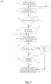
- the control process (20a, 20b) for controlling the icing of the evaporator (104), proposed by the invention ( Figs. 3 , 4 ), is for optimizing defrosting in a food blast chiller, which operates by means of a refrigeration circuit (10a, 10b) ( Figs. 1, 2 ) at evaporation temperatures lower than 0°C and is provided with a hot gas defrosting system of the evaporator.
- Said defrosting system is of the type having a by-pass line (116a, 116b) wherein the hot gas coming out of the compressor (101) is diverted to be directly injected into the inlet of the evaporator (104) without passing through the condenser (102), and with at least one valve for automatically adjusting flow (106), which is called defrosting valve or HGDV, which is the acronym for hot gas duct valve, which is connected to a control logic unit (120) for controlling the whole apparatus and provided with programs (121) that also comprise said algorithms (113a, 113b, 114a, 114b) for its opening and closing, on the basis of the continuous detection of said variable parameters (Pe, Ps, Tc, Te, Ts, 120-124) and of said ATD (ATD1-ATD4).
- HGDV which is the acronym for hot gas duct valve
- a refrigeration circuit which is equipped with a defrosting system of the type having a hot gas by-pass line (106a) including a defrosting valve HGDV (107, 111) that controls the entry thereof into the evaporator; in order to maximize the control of pressures and, as a consequence, of temperatures, a discharge line (108) of the compressor is included, having a dedicated valve (109), and an expansion member of the capillary tube type (103a).
- a defrosting system of the type having a hot gas by-pass line (106a) including a defrosting valve HGDV (107, 111) that controls the entry thereof into the evaporator; in order to maximize the control of pressures and, as a consequence, of temperatures, a discharge line (108) of the compressor is included, having a dedicated valve (109), and an expansion member of the capillary tube type (103a).
- variable parameters for the purpose of said detection of ATD, all said variable parameters (Pe, Ps, Tc, Te, Ts) measured by means of the respective probes (120-124), can be advantageously detected.
- a simplified variant (10b) ( Fig. 2 ), which is equivalent for the purpose of the invention, there is a direct by-pass line (106b, 107) without said discharge line (108, 109), and there is not even the probe detecting the suction pressure of the compressor, at the outlet of the evaporator; furthermore, the expansion member is different and is a thermostatic valve (103b). Therefore, in this configuration ( Fig. 2 ) the probe detecting the suction pressure (124, Ps) may be unreliable and is not provided.
- said defrosting valve HGDV (107), said probe in the cell (120, Tc) and at least one of said probes (121-124) for detecting the temperature of the cooling fluid, are installed and electronically connected with said control logic unit (111), whose programs (112) also include said calculation algorithms for opening (113a, 113b) and closing (114a, 114b) said valve HGDV.
- the invention proposes an advantageous control process (20a, 20b) for controlling the icing of the evaporator (104) in a blast chiller of the type having a refrigeration cycle with a hot gas by-pass line (106a, 106b, 107), comprising the following Phases:
- said valve HGDV (107) one continuously processes the detected value of ATD (ATD1, ATD2, ATD3, ATD4), which comes from the previous Phase of detection (201) and is progressively variable, according to said opening algorithms (113a, 113b) and closing algorithms (114a, 114b) in such a way as to open (203) and close (208) said valve HGDV (107) during ordinary operation, that is to say, with foodstuffs in the cell (105), keeping the evaporator (104) in a controlled minimum icing condition in which there is, if at all, a frost coat that does not affect heat exchange.
- Said opening algorithms (202, 113a-113b) activate the injection of hot gas (106a, 106b, 107, 203) into the evaporator (104) as soon as ice starts forming on top of said coat, acting as a thermal insulator that immediately changes said value ATD, while said closing algorithms (202, 114a-114b) interrupt said injection in correspondence of an opposite variation, considering both during opening (202-203, 113a-113b) and during closing (207-208, 114a-114b) a suitable variation tolerance.
- said detected value ATD (201, ATD1-ATD4) is assessed according to a first opening algorithm (20a, 113a, LC1) or to a second opening algorithm (20b, 113b, LC2), as set forth below.
- Said first algorithm (113a) considers the increase in ATD and provides opening when the detected value is greater than or equal to the pre-set optimal value (ATDset) plus a tolerated variation (vtATD) or deviation, thus applying one of the following cases on the basis of said detected parameters (Pe, Ps, Te, Ts):
- Said second algorithm (113b) assesses the growth rate, that is to say, considers said variation of ATD over time, calculating with greater sensitivity said opening, that is to say, when the tangent of the detected value (TanATD) is higher than or equal to the pre-set optimal value of said rate (TanATDset) plus a tolerated variation (vtATD):
- said detected value ATD is assessed according to a first closing algorithm (20a, 114a, LC1) or to a second closing algorithm (20b, 114b, LC2), as set forth below.
- Said first algorithm (114a) considers the decrease in ATD and provides closing when the detected value is lower than or equal to the pre-set optimal value (ATDset) minus twice said tolerated variation (vtATD), which here is increased to allow a margin for ordinary operativeness during blast chilling, and wherein said twofold subtraction indicates a preferred but not limitative value, thus applying one of the following cases on the basis of said detected parameters (Pe, Ps, Te, Ts):
- Said second algorithm (114b) considers the slowdown in the variation of ATD and provides closing when the tangent of the detected value (TanATD) is lower than the pre-set optimal value (TanATDset) minus a tolerated variation (vtTanATD):
- said control process (20a, 20b) in both said calculation logics (LC1, LC2), for good measure also includes the start of said Phase of closing (208) of the valve HGDV (107) when an excessive increase in the temperature in the cell (105) is detected, that is to say, when in a Phase of precautionary calculation (205) the detected temperature (Tc, 120) is greater than a pre-set optimal temperature (Tc/set) plus a tolerated variation (vtTc):
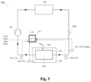
- the invention provides an equivalent electrical defrosting system (10c) ( Fig. 5 ), which does not include said by-pass line but comprises at least one electrical resistor (125) or a group of electrical resistors, in correspondence of the evaporator (104), with an opening-closing means (126) of the power supply of the resistors, and thus of defrosting, which is connected to the control logic unit (111) provided with the same programs (112) described above, which in this case automatically switch on and off said electrical resistors on the basis of the detection of the same variable parameters described above, by the same detection means (120-123) and by means of the same calculation logics.
- said electrical defrosting system (10c) is automatically controlled by a control process equivalent to the one described above (20a, 20b, 201-208, LCI-LC2) wherein, instead of adjusting the hot gas flow by opening (203, 204) and closing (208) said valve HGDV, the flow of electric current supplying the resistor (125) is controlled.
- a suitable opening-closing means (126) that switches it on and/or off like a circuit breaker, advantageously exploiting the intrinsic activation speed and the thermal inertia of said resistors, in such a way as to dynamically start and end a Phase of electrical defrosting (204) during ordinary operation, that is to say, with foodstuffs in the cell, keeping the evaporator (104) in a controlled minimum icing condition corresponding to a frost coat that does not thermally insulate.
Landscapes
- Engineering & Computer Science (AREA)
- Physics & Mathematics (AREA)
- Mechanical Engineering (AREA)
- Thermal Sciences (AREA)
- General Engineering & Computer Science (AREA)
- Chemical & Material Sciences (AREA)
- Combustion & Propulsion (AREA)
- Defrosting Systems (AREA)
- Air Conditioning Control Device (AREA)
- Investigating Or Analyzing Materials Using Thermal Means (AREA)
- Devices That Are Associated With Refrigeration Equipment (AREA)
Claims (6)
- Steuerungsprozess (20a, 20b) zur Steuerung der Vereisung eines Verdampfers (104) des kontinuierlichen und automatischen Typs, um das Abtauen in einem Lebensmittel-Schnellkühler zu optimieren, der mittels eines Kühlkreislaufs (10a, 10b, 10c, 101-104) bei Verdampfungstemperaturen unter 0°C arbeitet und mit einem Abtausystem des Verdampfers ausgestattet ist, wobei mindestens ein Öffnungs-/Schließmittel (107, 126) des Abtausystems mit einer Steuerlogikeinheit (111) verbunden ist, die mit Programmen (112) zur automatischen Durchführung des Öffnens und Schließens auf der Grundlage einer Erfassung variabler Parameter, wie z. B. der Temperatur, automatisch durchzuführen; wobei der Schnellkühler eine Zelle (105) zum Konservieren von Lebensmitteln und einen Kompressor (101), einen Kondensator (102), ein Expansionselement (103a, 103b) und den Verdampfer (104) aufweist, die in einem Kühlkreislauf enthalten sind, in dem ein Kältemittel fließt; das besagte Abtausystem weist Mittel zum Erfassen einer Temperatur in der Zelle und im Verdampfer auf; das besagte Abtausystem ist alternativ vom Heißgastyp (10a, 10b, 106-107) oder vom elektrischen Typ mit Widerständen (10c, 125-126); und wo im Fall eines Heißgas-Abtausystems (10a, 10b) eine Bypass-Leitung (106a, 106b) vorgesehen ist, in der das aus dem Kompressor (101) austretende Heißgas umgeleitet wird, um direkt in den Einlass des Verdampfers (104) eingespritzt zu werden, ohne durch den Kondensator (102) zu strömen, und wo das Öffnungs-/Schließmittel ein Ventil zum Einstellen des Heißgasstroms ist, vom Typ eines Abtauventils oder eines Heißgas-Abtauventils (107); und wo hingegen im Fall eines elektrischen Abtausystems (10c) mindestens ein elektrischer Widerstand (125) in der Nähe des Verdampfers (104) vorgesehen ist, wo die Öffnungs- /Schließvorrichtung (126) dazu dient, den dem Widerstand (125) zugeführten, elektrischen Strom zu steuern, indem sie diesen wie ein Schutzschalter ein- und/oder ausschaltet; der besagte Steuerungsprozess (20a, 20b) beinhaltet der Reihe nach eine anfängliche Startphase (200) und eine Stabilisierungsphase des Systems, eine Erfassungsphase (201) der besagten variablen Parameter mittels Fühlern, die mit der besagten Logikeinheit (111) verbunden sind, eine Berechnungsphase zum Öffnen (202) der besagten Öffnungs- und Schließvorrichtung (107, 126), eine Öffnungsphase (203) der Öffnungs-/Schließvorrichtung (107, 126), eine Abtauphase (204), in der der Abtauprozess durch das in den Verdampfer (104, 106-107) strömende Heißgas oder durch den in den Widerstand (125, 126) geleiteten, elektrischen Strom erfolgt, eine Phase zusätzlicher vorsorglicher Berechnung (205) mit einer optionalen Phase der Warnung (206), einer Phase der Berechnung zum Schließen (207) der Öffnungs-/Schließvorrichtung (107, 126) und einer abschließenden Phase des Schließens (208) der Öffnungs-/Schließvorrichtung (107, 126); eine Abtauphase (204), in der das Abtauen durch das in den Verdampfer (104, 106-107) strömende Heißgas oder durch den in den Widerstand (125, 126) geleiteten elektrischen Strom erfolgt, eine Phase zusätzlicher Sicherheitsberechnung (205) mit einer optionalen Warnphase (206), eine Berechnungsphase zum Schließen (207) der Öffnungs-/Schließvorrichtung (107, 126) und eine Abschlussphase zum Schließen (208) der Öffnungs-/Schließvorrichtung (107, 126); wobei in der Erfassungsphase (201) eine Lufttemperatur (TC) in der Zelle (105) und eine Temperatur des Kältemittels im Verdampfer (104) kontinuierlich erfasst werden und miteinander verglichen werden, um einen erfassten Wert für die Annäherungstemperaturdifferenz (ATD) zu erhalten, die der Differenz (ATD1, ATD2, ATD3 oder ATD4) zwischen der Lufttemperatur in der Zelle (105) und der Temperatur des Kältemittels entspricht, die anhand mindestens eines der folgenden Parameter ermittelt wird: Phase des Abtauvorgangs (204), in der das Abtauen durch das in den Verdampfer (104, 106-107) strömende Heißgas oder durch den in den Widerstand (125, 126) geleiteten elektrischen Strom erfolgt, eine Phase zusätzlicher vorsorglicher Berechnung (205) mit einer optionalen Phase der Warnung (206), einer Berechnungsphase zum Schließen (207) der Öffnungs-/Schließvorrichtung (107, 126) und einer Abschlussphase des Schließens (208) der Öffnungs-/Schließvorrichtung (107, 126); wo in der Erfassungsphase (201) eine Lufttemperatur (TC) in der Zelle (105) und eine Temperatur des Kältemittels im Verdampfer (104) kontinuierlich erfasst werden, sie miteinander verglichen werden, um einen erfassten Wert für die Annäherungstemperaturdifferenz (ATD) zu erhalten, die der Differenz (ATD1, ATD2, ATD3 oder ATD4) zwischen der Lufttemperatur in der Zelle (105) und der Temperatur des Kältemittels entspricht, die mit zumindest einem der folgenden Parameter ermittelt wird:• Ein Druck im Verdampfer (Pe), der mittels eines Fühlers (121) an seinem Einlass erfasst wird, entsprechend einer Gassättigungstemperatur (Tsat/e) im Verdampfer, wobei ATD1 einer Lufttemperatur (Tc) in der Zelle minus der Gassättigungstemperatur (Tsat/e) im Verdampfer entspricht, die aus dem Druck im Verdampfer (Pe) abgeleitet wird;• (Te), erfasst mittels eines Fühlers (122) am Einlass des Verdampfers, wobei ATD2 der Lufttemperatur (Tc) in der Zelle minus der Verdampfungstemperatur (Te) entspricht;• eine Ansaugtemperatur (Ts) des Kompressors, die durch einen Fühler (123) am Auslass des Verdampfers erfasst wird, wo ATD3 der Lufttemperatur (Tc) in der Zelle minus der Ansaugtemperatur (Ts) entspricht;• ein Ansaugdruck (Ps) des Kompressors, der mittels eines Fühlers (124) am Auslass des Verdampfers erfasst wird, entsprechend der Gassättigungstemperatur (Tsat/s) beim Ansaugen, wo ATD4 der Lufttemperatur (Tc) in der Zelle minus der Gassättigungstemperatur (Tsat/s) entspricht, die aus dem Ansaugdruck (Ps) abgeleitet wird;Besagter Kontrollprozess (20a, 20b), wo in einer ersten Berechnungslogik (20a, LC1) die erfasste Variation von ATD (201, ATD1-ATD4) eine Steigerung ist, die entsprechend den jeweiligen Öffnungs- (113a, 202) und Schließalgorithmen (114a, 207) kontinuierlich bewertet wird, oder wo in einer zweiten Berechnungslogik (20b, LC2) die erfasste Variation von ATD eine Wachstumsrate ist, die entsprechend den jeweiligen Öffnungs- (113b, 202) und Schließalgorithmen (114b, 207) kontinuierlich bewertet wird; und wo in den Berechnungsphasen für das Öffnen (202) und Schließen (207) der Öffnungs-/Schließvorrichtung (107, 126) die erfassten Werte von ATD (201, ATD1-ATD4) entsprechend den Öffnungsalgorithmen (113a-113b, 202) und Schließalgorithmen (114a-114b, 207) bearbeitet werden, die dazu bestimmt sind, die Öffnungs-Schließ-Vorrichtung (107, 126) automatisch zu öffnen (203) und zu schließen (208), um die Abtauphase (204) während des Normalbetriebs mit Lebensmitteln in der Zelle dynamisch zu starten und zu beenden, wobei der Verdampfer (104) in einem kontrollierten minimalen Vereisungszustand gehalten wird, der einer Reifschicht entspricht, die keine Wärmeisolierung bietet; und wobei die Öffnungsalgorithmen (113a-113b, 202) in der Öffnungsphase (203) die Öffnungs-Schließ-Einrichtung (107, 126) automatisch öffnen, wenn eine positive Änderung des ATD aufgrund des Eises auftritt, das sich auf der als Wärmedämmung wirkenden Schicht zu bilden beginnt; und wo die Schließalgorithmen (114a-114b, 207) in der Schließphase (208) die Öffnungs-Schließ-Einrichtung (107, 126) automatisch entsprechend einer entgegengesetzten Änderung des ATD aufgrund des Schmelzens des Eises schließen; wobei die Öffnungs- (113a-113b, 202) und Schließalgorithmen (114a-114b, 207) berücksichtigen eine zulässige Abweichung (vtATD, vtTanATD) in Bezug auf einen voreingestellten optimalen Wert (ATDset, TanATDset), wie einen Spielraum für die normale Funktionsfähigkeit des Kühlkreislaufs (101-104, 111-112); wobei die Algorithmen (113a, 113b, 114a, 114b) in den Programmen (112) der Steuerlogik (111) des Schnellkühlers integriert sind.
- Steuerungsprozess (20a) gemäß Anspruch 1, dadurch gekennzeichnet, dass gemäß der ersten Berechnungslogik (LC1) die Öffnungsphase (203) gestartet wird, sobald der Öffnungsalgorithmus (113a, 202) errechnet, dass der erfasste Wert ATD (201) höher oder genauso hoch ist wie der voreingestellte, optimale Wert (ATDset) zuzüglich einer zulässigen Abweichung (vtATD), und somit gemäß den erfassten Parametern (Pe, Ps, Te, Ts) einen der folgenden Fälle anwendet:•
 •
• •
• •
•
- Steuerungsprozess (20a) gemäß dem vorherigen Anspruch, dadurch gekennzeichnet, dass besagte Schließphase (208) gestartet wird, sobald der Schließalgorithmus (114a, 202) errechnet, dass der erfasste Wert ATD (201) kleiner oder identisch mit dem voreingestellten, optimalen Wert (ATDset) abzüglich zweimal der zulässigen Abweichung (vtATD) ist, und somit einen der folgenden Fälle gemäß den erfassten Parametern (Pe, Ps, Te, Ts) anwendet:•
 •
• •
• •
•
- Steuerungsprozess (20b) gemäß Anspruch 1, gekennzeichnet dadurch, dass gemäß der zweiten Berechnungslogik (LC2) die Öffnungsphase (203) gestartet wird, sobald der Öffnungsalgorithmus (113b) errechnet, dass der Tangens (TanATD) des erfassten Wertes ATD (201) höher oder genauso hoch ist wie ein voreingestellter optimaler Wert für den Tangens (TanATDset) ist:•

- Steuerungsprozess (20b) gemäß dem vorherigen Anspruch, gekennzeichnet dadurch, dass die Phase des Schließens (208) gestartet wird, sobald der Schließalgorithmus (114b) errechnet, dass der Tangens (TanATD) des erfassten Wertes ATD (201) niedriger ist als der voreingestellte, optimale Wert (TanATDset) abzüglich einer zulässigen Abweichung (vtTanATD) ist:•

- Steuerungsprozess (20a, 20b) gemäß Anspruch 1, dadurch gekennzeichnet, dass die Phase des Schließens (208) der Öffnungs-/Schließvorrichtung (107, 126) gestartet wird, wenn in einer Phase der Sicherheitsberechnung (205) die maximale Dauer in der Phase des Abtauvorgangs (204) überschritten wird, d. h. wenn:•und wo die Phase des Schließens (208) auch dann eingeleitet wird, wenn in der Phase der vorsorglichen Berechnung (205) ein übermäßiger Temperaturanstieg in der Zelle (105) eintritt, d. h. wenn die erfasste Temperatur (Tc, 120) höher ist als eine voreingestellte, optimale Temperatur (Tc/set) zuzüglich einer zulässigen Abweichung (vtTc): Tc > Tc/set + vtTc.

Applications Claiming Priority (1)
| Application Number | Priority Date | Filing Date | Title |
|---|---|---|---|
| IT102019000005938A IT201900005938A1 (it) | 2019-04-17 | 2019-04-17 | Procedimento di controllo del ghiacciamento dell’evaporatore, in un abbattitore di temperatura |
Publications (2)
| Publication Number | Publication Date |
|---|---|
| EP3726167A1 EP3726167A1 (de) | 2020-10-21 |
| EP3726167B1 true EP3726167B1 (de) | 2025-06-04 |
Family
ID=67384227
Family Applications (1)
| Application Number | Title | Priority Date | Filing Date |
|---|---|---|---|
| EP20020177.0A Active EP3726167B1 (de) | 2019-04-17 | 2020-04-14 | Steuerungsverfahren zur steuerung der vereisung eines verdampfers in einem blaskühler |
Country Status (2)
| Country | Link |
|---|---|
| EP (1) | EP3726167B1 (de) |
| IT (1) | IT201900005938A1 (de) |
Families Citing this family (1)
| Publication number | Priority date | Publication date | Assignee | Title |
|---|---|---|---|---|
| CN116448376B (zh) * | 2023-06-16 | 2023-08-18 | 中国空气动力研究与发展中心低速空气动力研究所 | 一种结冰风洞用的喷雾供气系统及调节方法 |
Family Cites Families (6)
| Publication number | Priority date | Publication date | Assignee | Title |
|---|---|---|---|---|
| DE10315524A1 (de) * | 2003-04-04 | 2004-10-14 | BSH Bosch und Siemens Hausgeräte GmbH | Kältegerät und Betriebsverfahren dafür |
| GB2456744A (en) * | 2007-08-30 | 2009-07-29 | Ebac Ltd | Auto-defrost refrigeration apparatus |
| EP2634515B1 (de) * | 2012-02-29 | 2019-09-04 | Electrolux Professional S.p.A. | Schockkühlervorrichtung und Verfahren zum Säubern einer Schockkühlervorrichtung |
| JP6095353B2 (ja) | 2012-12-13 | 2017-03-15 | 三菱電機株式会社 | 冷凍サイクル装置 |
| KR20160103858A (ko) * | 2015-02-25 | 2016-09-02 | 주식회사 리프코리아 | 자동 제상 시스템, 방법, 및 컴퓨터프로그램이 기록된 매체 |
| WO2018178405A1 (es) | 2017-03-28 | 2018-10-04 | Universitat De Lleida | Procedimiento de control adaptativo para sistemas de refrigeración |
-
2019
- 2019-04-17 IT IT102019000005938A patent/IT201900005938A1/it unknown
-
2020
- 2020-04-14 EP EP20020177.0A patent/EP3726167B1/de active Active
Also Published As
| Publication number | Publication date |
|---|---|
| EP3726167A1 (de) | 2020-10-21 |
| IT201900005938A1 (it) | 2020-10-17 |
Similar Documents
| Publication | Publication Date | Title |
|---|---|---|
| US5355686A (en) | Dual temperature control of refrigerator-freezer | |
| US6725680B1 (en) | Multi-compartment refrigerator control algorithm for variable speed evaporator fan motor | |
| US6606870B2 (en) | Deterministic refrigerator defrost method and apparatus | |
| US6694754B1 (en) | Refrigeration appliance with pulsed defrost heater | |
| US8726680B2 (en) | Electronic refrigeration control system including a variable speed compressor | |
| CN102748917B (zh) | 一种变频冰箱除霜控制方法 | |
| CN106352647B (zh) | 温度控制方法及温度控制装置和冰箱 | |
| EP2520880B1 (de) | Kühlbox | |
| CN103335469B (zh) | 风冷冰箱的控制方法及风冷冰箱 | |
| JP6454210B2 (ja) | 冷蔵庫 | |
| EP2746701A1 (de) | Kühlschrank mit nicht vereisendem Gefrierfach | |
| CN106766487B (zh) | 冰箱的控制方法 | |
| JPH0240950B2 (de) | ||
| KR20010108743A (ko) | 김치냉장고 및 그 제어방법 | |
| CN106225414A (zh) | 冰箱控制方法和电冰箱 | |
| RU2349847C2 (ru) | Холодильный аппарат и способ его эксплуатации | |
| JP6899736B2 (ja) | 低温貯蔵庫 | |
| US3899895A (en) | Automatic defrosting control system | |
| EP3726167A1 (de) | Steuerungsverfahren zur steuerung der vereisung des verdampfers in einem blaskühler | |
| EP0845643B1 (de) | Kühlanlage mit veränderlicher Zwangsbelüftung | |
| EP3673207B1 (de) | Ofen mit einer kühleinheit | |
| US3899896A (en) | Automatic defrosting control system | |
| EP2719978B1 (de) | Verfahren zur Regelung eines Haushaltskältegerät | |
| CN115325771B (zh) | 一种冰箱冷藏温度自调节控制系统及控制方法 | |
| CN118189508A (zh) | 减小冰箱化霜回温的控制方法及装置 |
Legal Events
| Date | Code | Title | Description |
|---|---|---|---|
| PUAI | Public reference made under article 153(3) epc to a published international application that has entered the european phase |
Free format text: ORIGINAL CODE: 0009012 |
|
| STAA | Information on the status of an ep patent application or granted ep patent |
Free format text: STATUS: THE APPLICATION HAS BEEN PUBLISHED |
|
| AK | Designated contracting states |
Kind code of ref document: A1 Designated state(s): AL AT BE BG CH CY CZ DE DK EE ES FI FR GB GR HR HU IE IS IT LI LT LU LV MC MK MT NL NO PL PT RO RS SE SI SK SM TR |
|
| AX | Request for extension of the european patent |
Extension state: BA ME |
|
| STAA | Information on the status of an ep patent application or granted ep patent |
Free format text: STATUS: REQUEST FOR EXAMINATION WAS MADE |
|
| 17P | Request for examination filed |
Effective date: 20210219 |
|
| STAA | Information on the status of an ep patent application or granted ep patent |
Free format text: STATUS: EXAMINATION IS IN PROGRESS |
|
| 17Q | First examination report despatched |
Effective date: 20220315 |
|
| P01 | Opt-out of the competence of the unified patent court (upc) registered |
Effective date: 20240305 |
|
| GRAP | Despatch of communication of intention to grant a patent |
Free format text: ORIGINAL CODE: EPIDOSNIGR1 |
|
| STAA | Information on the status of an ep patent application or granted ep patent |
Free format text: STATUS: GRANT OF PATENT IS INTENDED |
|
| INTG | Intention to grant announced |
Effective date: 20241216 |
|
| GRAS | Grant fee paid |
Free format text: ORIGINAL CODE: EPIDOSNIGR3 |
|
| GRAA | (expected) grant |
Free format text: ORIGINAL CODE: 0009210 |
|
| STAA | Information on the status of an ep patent application or granted ep patent |
Free format text: STATUS: THE PATENT HAS BEEN GRANTED |
|
| AK | Designated contracting states |
Kind code of ref document: B1 Designated state(s): AL AT BE BG CH CY CZ DE DK EE ES FI FR GB GR HR HU IE IS IT LI LT LU LV MC MK MT NL NO PL PT RO RS SE SI SK SM TR |
|
| REG | Reference to a national code |
Ref country code: GB Ref legal event code: FG4D |
|
| REG | Reference to a national code |
Ref country code: CH Ref legal event code: EP |
|
| REG | Reference to a national code |
Ref country code: DE Ref legal event code: R096 Ref document number: 602020052154 Country of ref document: DE |
|
| REG | Reference to a national code |
Ref country code: IE Ref legal event code: FG4D |
|
| REG | Reference to a national code |
Ref country code: NL Ref legal event code: MP Effective date: 20250604 |
|
| PG25 | Lapsed in a contracting state [announced via postgrant information from national office to epo] |
Ref country code: FI Free format text: LAPSE BECAUSE OF FAILURE TO SUBMIT A TRANSLATION OF THE DESCRIPTION OR TO PAY THE FEE WITHIN THE PRESCRIBED TIME-LIMIT Effective date: 20250604 Ref country code: ES Free format text: LAPSE BECAUSE OF FAILURE TO SUBMIT A TRANSLATION OF THE DESCRIPTION OR TO PAY THE FEE WITHIN THE PRESCRIBED TIME-LIMIT Effective date: 20250604 |
|
| REG | Reference to a national code |
Ref country code: LT Ref legal event code: MG9D |
|
| PG25 | Lapsed in a contracting state [announced via postgrant information from national office to epo] |
Ref country code: GR Free format text: LAPSE BECAUSE OF FAILURE TO SUBMIT A TRANSLATION OF THE DESCRIPTION OR TO PAY THE FEE WITHIN THE PRESCRIBED TIME-LIMIT Effective date: 20250905 Ref country code: NO Free format text: LAPSE BECAUSE OF FAILURE TO SUBMIT A TRANSLATION OF THE DESCRIPTION OR TO PAY THE FEE WITHIN THE PRESCRIBED TIME-LIMIT Effective date: 20250904 |
|
| PG25 | Lapsed in a contracting state [announced via postgrant information from national office to epo] |
Ref country code: PL Free format text: LAPSE BECAUSE OF FAILURE TO SUBMIT A TRANSLATION OF THE DESCRIPTION OR TO PAY THE FEE WITHIN THE PRESCRIBED TIME-LIMIT Effective date: 20250604 |
|
| PG25 | Lapsed in a contracting state [announced via postgrant information from national office to epo] |
Ref country code: BG Free format text: LAPSE BECAUSE OF FAILURE TO SUBMIT A TRANSLATION OF THE DESCRIPTION OR TO PAY THE FEE WITHIN THE PRESCRIBED TIME-LIMIT Effective date: 20250604 |
|
| PG25 | Lapsed in a contracting state [announced via postgrant information from national office to epo] |
Ref country code: HR Free format text: LAPSE BECAUSE OF FAILURE TO SUBMIT A TRANSLATION OF THE DESCRIPTION OR TO PAY THE FEE WITHIN THE PRESCRIBED TIME-LIMIT Effective date: 20250604 |
|
| PG25 | Lapsed in a contracting state [announced via postgrant information from national office to epo] |
Ref country code: RS Free format text: LAPSE BECAUSE OF FAILURE TO SUBMIT A TRANSLATION OF THE DESCRIPTION OR TO PAY THE FEE WITHIN THE PRESCRIBED TIME-LIMIT Effective date: 20250904 |
|
| PG25 | Lapsed in a contracting state [announced via postgrant information from national office to epo] |
Ref country code: LV Free format text: LAPSE BECAUSE OF FAILURE TO SUBMIT A TRANSLATION OF THE DESCRIPTION OR TO PAY THE FEE WITHIN THE PRESCRIBED TIME-LIMIT Effective date: 20250604 |
|
| PG25 | Lapsed in a contracting state [announced via postgrant information from national office to epo] |
Ref country code: NL Free format text: LAPSE BECAUSE OF FAILURE TO SUBMIT A TRANSLATION OF THE DESCRIPTION OR TO PAY THE FEE WITHIN THE PRESCRIBED TIME-LIMIT Effective date: 20250604 |
|
| PG25 | Lapsed in a contracting state [announced via postgrant information from national office to epo] |
Ref country code: PT Free format text: LAPSE BECAUSE OF FAILURE TO SUBMIT A TRANSLATION OF THE DESCRIPTION OR TO PAY THE FEE WITHIN THE PRESCRIBED TIME-LIMIT Effective date: 20251006 |
|
| REG | Reference to a national code |
Ref country code: AT Ref legal event code: MK05 Ref document number: 1800677 Country of ref document: AT Kind code of ref document: T Effective date: 20250604 |
|
| PG25 | Lapsed in a contracting state [announced via postgrant information from national office to epo] |
Ref country code: IS Free format text: LAPSE BECAUSE OF FAILURE TO SUBMIT A TRANSLATION OF THE DESCRIPTION OR TO PAY THE FEE WITHIN THE PRESCRIBED TIME-LIMIT Effective date: 20251004 |
|
| PG25 | Lapsed in a contracting state [announced via postgrant information from national office to epo] |
Ref country code: AT Free format text: LAPSE BECAUSE OF FAILURE TO SUBMIT A TRANSLATION OF THE DESCRIPTION OR TO PAY THE FEE WITHIN THE PRESCRIBED TIME-LIMIT Effective date: 20250604 Ref country code: SM Free format text: LAPSE BECAUSE OF FAILURE TO SUBMIT A TRANSLATION OF THE DESCRIPTION OR TO PAY THE FEE WITHIN THE PRESCRIBED TIME-LIMIT Effective date: 20250604 |
|
| PG25 | Lapsed in a contracting state [announced via postgrant information from national office to epo] |
Ref country code: CZ Free format text: LAPSE BECAUSE OF FAILURE TO SUBMIT A TRANSLATION OF THE DESCRIPTION OR TO PAY THE FEE WITHIN THE PRESCRIBED TIME-LIMIT Effective date: 20250604 |
|
| PG25 | Lapsed in a contracting state [announced via postgrant information from national office to epo] |
Ref country code: EE Free format text: LAPSE BECAUSE OF FAILURE TO SUBMIT A TRANSLATION OF THE DESCRIPTION OR TO PAY THE FEE WITHIN THE PRESCRIBED TIME-LIMIT Effective date: 20250604 |
|
| PG25 | Lapsed in a contracting state [announced via postgrant information from national office to epo] |
Ref country code: RO Free format text: LAPSE BECAUSE OF FAILURE TO SUBMIT A TRANSLATION OF THE DESCRIPTION OR TO PAY THE FEE WITHIN THE PRESCRIBED TIME-LIMIT Effective date: 20250604 Ref country code: SK Free format text: LAPSE BECAUSE OF FAILURE TO SUBMIT A TRANSLATION OF THE DESCRIPTION OR TO PAY THE FEE WITHIN THE PRESCRIBED TIME-LIMIT Effective date: 20250604 |
|
| REG | Reference to a national code |
Ref country code: DE Ref legal event code: R097 Ref document number: 602020052154 Country of ref document: DE |
|
| PLBE | No opposition filed within time limit |
Free format text: ORIGINAL CODE: 0009261 |
|
| STAA | Information on the status of an ep patent application or granted ep patent |
Free format text: STATUS: NO OPPOSITION FILED WITHIN TIME LIMIT |
|
| PG25 | Lapsed in a contracting state [announced via postgrant information from national office to epo] |
Ref country code: DK Free format text: LAPSE BECAUSE OF FAILURE TO SUBMIT A TRANSLATION OF THE DESCRIPTION OR TO PAY THE FEE WITHIN THE PRESCRIBED TIME-LIMIT Effective date: 20250604 |
|
| REG | Reference to a national code |
Ref country code: CH Ref legal event code: L10 Free format text: ST27 STATUS EVENT CODE: U-0-0-L10-L00 (AS PROVIDED BY THE NATIONAL OFFICE) Effective date: 20260416 |
|
| 26N | No opposition filed |
Effective date: 20260305 |