EP3726099B1 - Parksperranordnung - Google Patents
Parksperranordnung Download PDFInfo
- Publication number
- EP3726099B1 EP3726099B1 EP20169630.9A EP20169630A EP3726099B1 EP 3726099 B1 EP3726099 B1 EP 3726099B1 EP 20169630 A EP20169630 A EP 20169630A EP 3726099 B1 EP3726099 B1 EP 3726099B1
- Authority
- EP
- European Patent Office
- Prior art keywords
- parking lock
- lock
- actuator
- parking
- locking
- Prior art date
- Legal status (The legal status is an assumption and is not a legal conclusion. Google has not performed a legal analysis and makes no representation as to the accuracy of the status listed.)
- Active
Links
Images

Classifications
-
- F—MECHANICAL ENGINEERING; LIGHTING; HEATING; WEAPONS; BLASTING
- F16—ENGINEERING ELEMENTS AND UNITS; GENERAL MEASURES FOR PRODUCING AND MAINTAINING EFFECTIVE FUNCTIONING OF MACHINES OR INSTALLATIONS; THERMAL INSULATION IN GENERAL
- F16H—GEARING
- F16H63/00—Control outputs from the control unit to change-speed- or reversing-gearings for conveying rotary motion or to other devices than the final output mechanism
- F16H63/02—Final output mechanisms therefor; Actuating means for the final output mechanisms
- F16H63/30—Constructional features of the final output mechanisms
- F16H63/34—Locking or disabling mechanisms
- F16H63/3416—Parking lock mechanisms or brakes in the transmission
- F16H63/3425—Parking lock mechanisms or brakes in the transmission characterised by pawls or wheels
- F16H63/3433—Details of latch mechanisms, e.g. for keeping pawls out of engagement
-
- F—MECHANICAL ENGINEERING; LIGHTING; HEATING; WEAPONS; BLASTING
- F16—ENGINEERING ELEMENTS AND UNITS; GENERAL MEASURES FOR PRODUCING AND MAINTAINING EFFECTIVE FUNCTIONING OF MACHINES OR INSTALLATIONS; THERMAL INSULATION IN GENERAL
- F16H—GEARING
- F16H63/00—Control outputs from the control unit to change-speed- or reversing-gearings for conveying rotary motion or to other devices than the final output mechanism
- F16H63/02—Final output mechanisms therefor; Actuating means for the final output mechanisms
- F16H63/30—Constructional features of the final output mechanisms
- F16H63/34—Locking or disabling mechanisms
- F16H63/3416—Parking lock mechanisms or brakes in the transmission
- F16H63/3425—Parking lock mechanisms or brakes in the transmission characterised by pawls or wheels
-
- B—PERFORMING OPERATIONS; TRANSPORTING
- B60—VEHICLES IN GENERAL
- B60T—VEHICLE BRAKE CONTROL SYSTEMS OR PARTS THEREOF; BRAKE CONTROL SYSTEMS OR PARTS THEREOF, IN GENERAL; ARRANGEMENT OF BRAKING ELEMENTS ON VEHICLES IN GENERAL; PORTABLE DEVICES FOR PREVENTING UNWANTED MOVEMENT OF VEHICLES; VEHICLE MODIFICATIONS TO FACILITATE COOLING OF BRAKES
- B60T1/00—Arrangements of braking elements, i.e. of those parts where braking effect occurs specially for vehicles
- B60T1/005—Arrangements of braking elements, i.e. of those parts where braking effect occurs specially for vehicles by locking of wheel or transmission rotation
-
- F—MECHANICAL ENGINEERING; LIGHTING; HEATING; WEAPONS; BLASTING
- F16—ENGINEERING ELEMENTS AND UNITS; GENERAL MEASURES FOR PRODUCING AND MAINTAINING EFFECTIVE FUNCTIONING OF MACHINES OR INSTALLATIONS; THERMAL INSULATION IN GENERAL
- F16H—GEARING
- F16H63/00—Control outputs from the control unit to change-speed- or reversing-gearings for conveying rotary motion or to other devices than the final output mechanism
- F16H63/02—Final output mechanisms therefor; Actuating means for the final output mechanisms
- F16H63/30—Constructional features of the final output mechanisms
- F16H63/34—Locking or disabling mechanisms
- F16H63/3416—Parking lock mechanisms or brakes in the transmission
- F16H63/3441—Parking locks engaging axially
-
- F—MECHANICAL ENGINEERING; LIGHTING; HEATING; WEAPONS; BLASTING
- F16—ENGINEERING ELEMENTS AND UNITS; GENERAL MEASURES FOR PRODUCING AND MAINTAINING EFFECTIVE FUNCTIONING OF MACHINES OR INSTALLATIONS; THERMAL INSULATION IN GENERAL
- F16H—GEARING
- F16H63/00—Control outputs from the control unit to change-speed- or reversing-gearings for conveying rotary motion or to other devices than the final output mechanism
- F16H63/02—Final output mechanisms therefor; Actuating means for the final output mechanisms
- F16H63/30—Constructional features of the final output mechanisms
- F16H63/34—Locking or disabling mechanisms
- F16H63/3416—Parking lock mechanisms or brakes in the transmission
- F16H63/3458—Parking lock mechanisms or brakes in the transmission with electric actuating means, e.g. shift by wire
- F16H63/3466—Parking lock mechanisms or brakes in the transmission with electric actuating means, e.g. shift by wire using electric motors
-
- F—MECHANICAL ENGINEERING; LIGHTING; HEATING; WEAPONS; BLASTING
- F16—ENGINEERING ELEMENTS AND UNITS; GENERAL MEASURES FOR PRODUCING AND MAINTAINING EFFECTIVE FUNCTIONING OF MACHINES OR INSTALLATIONS; THERMAL INSULATION IN GENERAL
- F16H—GEARING
- F16H63/00—Control outputs from the control unit to change-speed- or reversing-gearings for conveying rotary motion or to other devices than the final output mechanism
- F16H63/02—Final output mechanisms therefor; Actuating means for the final output mechanisms
- F16H63/30—Constructional features of the final output mechanisms
- F16H63/34—Locking or disabling mechanisms
- F16H63/3416—Parking lock mechanisms or brakes in the transmission
- F16H63/3458—Parking lock mechanisms or brakes in the transmission with electric actuating means, e.g. shift by wire
- F16H63/3475—Parking lock mechanisms or brakes in the transmission with electric actuating means, e.g. shift by wire using solenoids
-
- F—MECHANICAL ENGINEERING; LIGHTING; HEATING; WEAPONS; BLASTING
- F16—ENGINEERING ELEMENTS AND UNITS; GENERAL MEASURES FOR PRODUCING AND MAINTAINING EFFECTIVE FUNCTIONING OF MACHINES OR INSTALLATIONS; THERMAL INSULATION IN GENERAL
- F16H—GEARING
- F16H63/00—Control outputs from the control unit to change-speed- or reversing-gearings for conveying rotary motion or to other devices than the final output mechanism
- F16H63/02—Final output mechanisms therefor; Actuating means for the final output mechanisms
- F16H63/30—Constructional features of the final output mechanisms
- F16H63/38—Detents
Definitions
- a parking lock arrangement of said type that is intended for a motor vehicle with electric drive comprises a lock element, which interacts with a parking lock wheel, and a parking lock actuator, which serves for adjusting the lock element between a locking position and a release position.
- the parking lock arrangement is intended to prevent, in a locking position, the motor vehicle from inadvertently rolling away.
- the drive train is locked via a parking lock wheel which is arranged rotationally conjointly on a shaft of the drive train and which has a toothing and which, by means of a parking lock pawl mounted pivotably on a parallel axle and having a lock element in the form of a locking tooth, can be locked in a form-fitting manner at the toothing.
- the parking lock pawl is preloaded by the force of a restoring spring either away from the parking lock wheel into an unlocked position or towards the parking lock wheel into the locking position.
- hydraulic parking lock actuators For the purpose of pivoting the parking lock pawl counter to the force of the restoring spring, besides hydraulic parking lock actuators, use may also be made of electrical or electromechanical parking lock actuators which serve for generating a linear movement, or an at least substantially linear movement, via which an actuation element is movable towards the parking lock pawl in order to pivot the latter.
- DE 10 2007 010 940 B4 discloses a parking lock arrangement having a lock element which is formed by a locking tooth of a rotatably mounted pawl which, by means of a control element which is movable back and forth in a substantially linear manner, is adjustable between a release position and a locking position which arrests a gearing.
- the control element is actuated by an actuator which comprises two redundant electromagnets.
- Document DE 10 2009 023 498 A1 discloses a parking lock arrangement of the type mentioned in the introduction for a motor vehicle with electric drive.
- Said parking lock arrangement comprises a sliding element which is movable in a translational manner by an actuator and which, via a conical pressure surface, interacts with a pivotably mounted pawl.
- the pawl has on the inside a locking tooth which can, as a lock element, be adjusted between a locking position and an unlocking position during a pivoting movement of the pawl along a circular movement path. In the locking position, the locking tooth engages in a form-fitting manner into one of multiple latching cutouts which are distributed over the circumference of a parking lock wheel.
- the parking lock wheel is connected rotationally conjointly to a shaft of the drive train of the motor vehicle, with the result, in the locking position of the pawl or in the locking position of the lock element, that the drive train is prevented from performing a rotational movement and thus the motor vehicle is prevented from rolling away.
- the unlocking position selectively actuable via the actuator, of the pawl or in the associated release position of the lock element, this form-fitting engagement is eliminated, with the result that the components of the drive train can rotate freely.
- the present invention is based on the object of proposing a parking lock arrangement for an electromotively driven motor vehicle (also called electric vehicle) which is of the simplest possible design.
- the lock element is moved only in a translational manner between the locking position and the release position.
- a major advantage of the invention as claimed in claim 1 is that no parking lock pawl is required. Therefore, besides a particularly simple construction, the parking lock arrangement according to the invention is also distinguished especially by a compact design, which allows simple accommodation even with confined installation space conditions.
- a further advantage is that, in this case, owing to the omission of a spring-loaded pawl, it is also possible for the parking lock actuator to be of particular simple design.
- the lock element is a bar or pin which is mounted in a housing of the parking lock actuator and which is mounted in an axially displaceable manner.
- the pin or bar may be mounted directly or indirectly, in particular via a rod fastened thereto.
- the pin or a rod connected to the latter is, via slide bearings, mounted in an axially displaceable manner in a housing of the parking lock actuator.
- the parking lock actuator has a housing which is in particular of multi-part design and in which the lock element is mounted in an axially displaceable manner, wherein a free end of the lock element, at least in the locking position, projects from the housing and engages into a cutout of the parking lock wheel in a form-fitting manner outside the housing.
- the cutouts in the parking lock wheel are formed in an axial direction, wherein the lock element is mounted so as to be displaceable parallel to the axis of rotation of the parking lock wheel and, in the locking position, engages axially into one of the cutouts.
- the axial cutouts may in this case also be formed as passage bores.
- the cutouts in the parking lock wheel are formed in a radial direction, wherein the lock element is mounted so as to be displaceable perpendicular to the axis of rotation of the parking lock wheel and, in the locking position, engages radially into one of the cutouts.
- the cutouts as in the case of the conventional parking locks operating with a pawl, are arranged in the outer circumference of the parking lock wheel in a manner similar to a toothed gear.
- the parking lock actuator is an electromechanical actuator.
- the parking lock actuator comprises an electromagnet in the form of a solenoid having a solenoid plunger which interacts with a coil, wherein the solenoid plunger is connected fixedly to the lock element or forms, with a sub-region thereof, the lock element.
- the lock element can be adjusted between the locking position and the release position.
- the parking lock actuator comprises two axially adjacently arranged solenoids having a reversing solenoid acting in both directions and having two axially adjacently situated coils.
- both coils can be electrically energized separately from one another in order, in this way, to adjust the lock element between the locking position and the release position.
- locking means which act in a form-fitting and/or force-fitting manner and by way of which the lock element can, in both positions, be fixed mechanically, in particular in a latching manner, in each case. Electrical energization of the coil(s) of the solenoid is then required only briefly for an adjustment of the lock element, while the lock element is securely mechanically held in the two positions, in each case even without electrical energization of the coil(s).
- a particularly simple embodiment of the locking means is achieved here in that these comprise a locking body which is loaded by a compression spring, in particular a spring-loaded ball, which locking body, in the locking position and in the release position, engages, in each case in a latching manner, into a cutout, in particular into a spherical cap-shaped or spherical dome-shaped depression, which is connected fixedly to the lock element.
- the compression spring is matched to the solenoid such that the holding force exerted by said compression spring can be overcome with the electrical energization of a coil.
- the locking means may comprise an additional electric magnet by way of which, with electrical energization, a spring-loaded locking body, for releasing the lock element, can be adjusted into an unlocking position.
- the electromechanical parking lock actuator comprises an electric motor whose output shaft is operatively connected to the lock element via a gearing mechanism, wherein the gearing mechanism serves to convert a rotational movement of the output shaft of the motor into an axial movement of the lock element.
- the gearing mechanism serves to convert a rotational movement of the output shaft of the motor into an axial movement of the lock element.
- At least one sensor formed as an angle sensor, is arranged for position detection of the parking lock wheel.
- the sensor detects a position of the parking lock wheel which differs from this state, the electric motor of the vehicle can firstly be activated by a control unit of the parking lock arrangement such that the parking lock wheel is rotated slightly into the desired position with a cutout oriented exactly to the lock element.
- one or more sensors are provided in the parking lock arrangement for position detection of the lock element.
- an indication can be made to a control unit of the parking lock arrangement as to whether the lock element is situated in the locking position or in the release position.
- the present invention also relates to a motor vehicle with electric drive which comprises a parking lock arrangement of the above-described type.
- the motor vehicle may either be driven purely electromotively or have a hybrid drive, that is to say, in addition to an electric motor, also have an internal combustion engine.
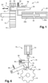
- FIG. 1 shows a parking lock arrangement 10 which is intended for installation in a motor vehicle driven by an electric motor.
- the parking lock arrangement 10 has, in a manner known per se, a parking lock wheel 12 which is arranged in a rotationally conjoint and axially fixed manner on a shaft 14 in the drive train of the motor vehicle.
- the parking lock wheel 12 has between its outer circumference 16 and the shaft 14 multiple cutouts 18, which are formed here by passage bores and are distributed uniformly over the circumference of said parking lock wheel.
- the parking lock arrangement 10 comprises a lock element 20, which is formed here by a pin.
- the lock element 20 is mounted in an actuator housing 22 (illustrated only in Figures 2 to 5 ), which is fixed relative to the chassis of the motor vehicle, so as to be adjustable in a translational manner between a locking position S ( Figures 1 , 4 and 5 ) and a release position F ( Figures 2 and 3 ) along a rectilinear movement path 24 in the direction of the longitudinal extent of said lock element.
- the lock element 20 engages in a form-fitting manner into one of the cutouts 18 of the parking lock wheel 12 such that the parking lock wheel 12 and the shaft 14 in the drive train, which is connected rotationally conjointly thereto, and ultimately also the wheels of the motor vehicle, which are operatively connected rotationally conjointly thereto, are prevented from performing a rotational movement.
- the release position F the lock element 20 is in a state fully retracted from the cutouts 18 of the parking lock wheel 12, with the result that said lock element is out of engagement with said cutouts, and that the parking lock wheel 20 and thus also the drive train and the wheels of the motor vehicle that are operatively connected thereto are freely rotatable.
- an electromagnetic parking lock actuator 26 which comprises here a reversing solenoid 28 having two axially adjacently arranged coils 30a and 30b and having a solenoid plunger 32 which is displaceably received therein.
- the two coils 30a and 30b are arranged parallel to ( Figure 1 ) or coaxially with ( Figures 2 to 5 ) the longitudinal extent of the lock element 20, with the result that the solenoid plunger 32 can move back and forth in a rectilinear manner parallel to or coaxially with the lock element 20.
- the solenoid plunger 32 is connected fixedly to the lock element 20, with the result that, by selective electrical energization of one of the two coils 30a or 30b, the solenoid plunger 32 is drawn into the respective coil 30a or 30b and in the process the lock element 20 is also correspondingly adjusted along its rectilinear movement path 24.
- the electrical energization of the coils 30a, 30b is realized via a control unit (not illustrated here) of the parking lock arrangement 10.
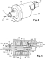
- the parking lock actuator 26 shown in the exemplary embodiment in Figure 2 comprises an actuator housing 22, which is preferably injection-moulded from a plastic and, via fastening lugs (not illustrated in more detail here), can be fastened in the motor vehicle in a manner known per se, for example by means of screws.
- the actuator housing 22 is closed by a housing cover 34 which is manufactured from metal. Integrally formed on the housing cover 34 is a collar 36 having an inner duct, in which the pin 20 forming the lock element is received in an axially displaceable manner.
- the pin is fastened to the front end of an actuation rod 38 which, by means of two slide bearings 40, is mounted in an axially displaceable manner in the actuator housing 22.
- the two coils 30a and 30b of the reversing solenoid 28 are received in in each case one coil carrier 42, which for its part is accommodated in in each case one magnet housing 44, which is of multi-part design here.
- the solenoid plunger 32, formed by an iron core, of the reversing solenoid 28 is fastened on the actuation rod 38 radially inside the two magnet housings 44.
- the solenoid plunger 32 is situated axially between the two slide bearings 40, which are attached to the inner side of the two magnet housings 44.
- locking means 48 which act in a form-fitting and force-fitting manner on the collar 36.
- a ball 52 loaded by a compression spring 50 is received in a transverse bore and, in the locking position S and the release position F, engages in a latching manner in in each case one notch 54S or 54F, respectively of the pin 20.
- the parking lock actuator 26 has an common electrical interface 60 integrated into the actuator housing 22, which interface is arranged in the rear region of the actuator housing 22.
- the parking lock arrangement comprises a pivotably mounted pawl 62 and a parking lock wheel 12 which has on the outer circumferential side a toothing 64.
- the pawl 62 has a locking tooth 66, which forms the lock element 20 and, in the locking position S, in a conventional manner, engages from the outside into a cutout 18 of the parking lock wheel 12 that is formed in the toothing 64.
- the pawl 62 is preloaded into the locking position S by a spring 68.
- a solenoid 70 is arranged as a parking lock actuator.
- the solenoid plunger 74 Upon electrical energization of the coil 72 thereof, the solenoid plunger 74 is drawn into the coil 72 and in the process the pawl 62, which is connected thereto, is, counter to the preload force exerted by the spring 68, pivoted to such an extent that the locking tooth 66 is no longer in engagement with the toothing 64 of the parking lock wheel 12.
- an additional electrical locking magnet 76 having a spring-loaded solenoid plunger 78, which blocks the solenoid plunger 74 of the solenoid 70 in its position in which it is drawn into the coil 72. Only by electrical energization of the coil 80 of the locking magnet 76 is the solenoid plunger 78 thereof drawn into the coil 80 counter to the force of the spring 82 acting thereon such that the solenoid plunger 74 of the solenoid 70 is released and the pawl 62, as a consequence of the preload force exerted by the spring 68, pivots back into the locking position.
Landscapes
- Engineering & Computer Science (AREA)
- General Engineering & Computer Science (AREA)
- Mechanical Engineering (AREA)
- Gear-Shifting Mechanisms (AREA)
- Braking Arrangements (AREA)
- Lock And Its Accessories (AREA)
Claims (7)
- Parksperranordnung (10) für ein elektromotorisch angetriebenes Kraftfahrzeug, Folgendes umfassend:- ein Parksperrenrad (12), das bezüglich einer Welle (14) im Antriebsstrang rotatorisch verbunden ist und das mehrere Ausschnitte (18) aufweist,- ein Sperrelement (20), das zwischen einer Sperrposition (S-Fig.4-5) und einer Freigabeposition (F-Fig.2-3) entlang eines Bewegungspfads (24) bewegbar ist und das, in der Sperrposition (S), in einer formschlüssigen Weise in Eingriff mit einem Ausschnitt (18) des Parksperrenrades (12) kommt und, in der Freigabeposition (F), nicht im Eingriff mit den Ausschnitten (18) des Parksperrenrades (12) ist,- einen Parksperrenaktuator (26), der mit dem Sperrelement (20) wirkverbunden ist und mittels dessen das Sperrelement (20) zwischen der Sperrposition (S) und der Freigabeposition (F) entlang seines Bewegungspfads (24) anpassbar ist, wobei der Parksperrenaktuator (26) ein elektromechanischer Aktuator ist, umfassend ein Umkehrmagnetventil (28), das in beide Richtungen wirkt und einen Magnetventilkolben (32) aufweist, der fest mit dem Sperrelement (20) verbunden ist,- das Sperrelement (20) ein Stift oder Stab ist, der in einer axial versetzbaren Weise in einem Gehäuse (22) des Parksperrenaktuators (26) montiert ist,- zumindest einen Sensor (56S, 56F), der angeordnet ist zur Positionsdetektion des Sperrelements (20),dadurch gekennzeichnet, dass
der Parksperrenaktuator (26) zwei axial angrenzend befindliche Spulen (30a, 30b) aufweist, die den Magnetventilkolben (32) umgeben, und dadurch, dass, zum Zwecke des Verbindens der Spulen (30a, 30b) und des Positionssensors (56S, 56F) mit einer externen Steuereinheit, der Parksperrenaktuator (26) eine gemeinsame elektrische Schnittstelle (60) aufweist, die in das Aktuatorgehäuse (22) integriert ist. - Parksperranordnung (10) nach Anspruch 1, dadurch gekennzeichnet, dass die Ausschnitte (18) im Parksperrenrad (12) in einer axialen Richtung gebildet sind, und dadurch, dass das Sperrelement (20) montiert ist, um parallel zur Rotationsachse des Parksperrenrades (12) versetzbar zu sein, und, in der Sperrposition (S), axial in einen der Ausschnitte (18) eingreift.
- Parksperranordnung (10) nach Anspruch 1, dadurch gekennzeichnet, dass die Ausschnitte (18) im Parksperrenrad (12) in einer radialen Richtung gebildet sind, und dadurch, dass das Sperrelement (20) montiert ist, um senkrecht zur Rotationsachse des Parksperrenrades (12) versetzbar zu sein, und, in der Sperrposition (S), radial in einen der Ausschnitte (18) eingreift.
- Parksperranordnung (10) nach einem der vorhergehenden Ansprüche, dadurch gekennzeichnet, dass das Sperrelement (20) in der Lage ist, in der Sperrposition (S) und in der Freigabeposition (F) gesperrt zu werden, in jedem Fall durch Sperrmittel (48), die in einer formschlüssigen und/oder kraftschlüssigen Weise wirken.
- Parksperranordnung (10) nach Anspruch 4, dadurch gekennzeichnet, dass das Sperrmittel (48) einen Sperrkörper (52) umfasst, der durch eine Druckfeder (50) belastet wird, insbesondere eine federbelastete Kugel (52), wobei der Sperrkörper, in der Sperrposition (S) und in der Freigabeposition (F), in jedem Fall in einer verriegelnden Weise in einen Ausschnitt (54) eingreift, insbesondere in eine sphärische kappenförmige Vertiefung, die fest mit dem Sperrelement (20) verbunden ist.
- Parksperranordnung (10) nach einem der vorhergehenden Ansprüche, dadurch gekennzeichnet, dass zumindest ein Sensor zur Positionsdetektion des Parksperrenrades (12) angeordnet ist.
- Elektromotorisch angetriebes Kraftfahrzeug, dadurch gekennzeichnet, dass es eine Parksperranordnung (10) nach einem der vorhergehenden Ansprüche aufweist.
Applications Claiming Priority (1)
| Application Number | Priority Date | Filing Date | Title |
|---|---|---|---|
| DE102019110384.3A DE102019110384A1 (de) | 2019-04-18 | 2019-04-18 | Parksperrenanordnung |
Publications (2)
| Publication Number | Publication Date |
|---|---|
| EP3726099A1 EP3726099A1 (de) | 2020-10-21 |
| EP3726099B1 true EP3726099B1 (de) | 2024-11-06 |
Family
ID=70390748
Family Applications (1)
| Application Number | Title | Priority Date | Filing Date |
|---|---|---|---|
| EP20169630.9A Active EP3726099B1 (de) | 2019-04-18 | 2020-04-15 | Parksperranordnung |
Country Status (4)
| Country | Link |
|---|---|
| US (1) | US11402019B2 (de) |
| EP (1) | EP3726099B1 (de) |
| CN (1) | CN111828627B (de) |
| DE (1) | DE102019110384A1 (de) |
Families Citing this family (17)
| Publication number | Priority date | Publication date | Assignee | Title |
|---|---|---|---|---|
| DE102019135309A1 (de) * | 2019-12-19 | 2021-06-24 | Valeo Siemens Eautomotive Germany Gmbh | Parksperrenaktuator, Parksperre, elektrische Antriebseinrichtung und Fahrzeug |
| IT202000004459A1 (it) * | 2020-03-03 | 2021-09-03 | Piaggio & C Spa | Un freno di stazionamento per un motoveicolo e motoveicolo comprendente il freno di stazionamento |
| US11577798B2 (en) | 2020-08-12 | 2023-02-14 | Damon Motors Inc. | Locking device for electric motorcycle |
| CN112747115B (zh) * | 2020-12-29 | 2022-07-01 | 厦门迈斯磁电有限公司 | 一种双稳态防水驻车锁用电磁铁及制造工艺 |
| DE102021208321A1 (de) | 2021-07-30 | 2023-02-02 | Vitesco Technologies GmbH | Verfahren zur Verriegelung einer Parksperre, Computerprogramm, Computerprogrammprodukt und Fahrzeug |
| DE102021208324B4 (de) | 2021-07-30 | 2025-08-07 | Schaeffler Technologies AG & Co. KG | Verfahren zur Sicherung eines Fahrzeugs, Computerprogramm, Computerprogrammprodukt und Fahrzeug |
| DE102021208322A1 (de) | 2021-07-30 | 2023-02-02 | Vitesco Technologies GmbH | Verfahren zur Abbremsung eines Fahrzeugs, Computerprogramm, Computerprogrammprodukt und Fahrzeug |
| DE102021208323A1 (de) | 2021-07-30 | 2023-02-02 | Vitesco Technologies GmbH | Verfahren zur Positionierung eines Fahrzeugs, Computerprogramm, Computerprogrammprodukt und Fahrzeug |
| DE102021209379B3 (de) * | 2021-08-26 | 2023-01-26 | Continental Automotive Technologies GmbH | Verfahren zum Betätigen eines Blockierstößels, Betätigungseinheit und Fahrzeugbremse |
| US12025222B1 (en) | 2022-07-22 | 2024-07-02 | GreenPower Motor Company | External parking lock for electric drive systems |
| DE102023202014B3 (de) | 2023-03-07 | 2024-03-14 | Vitesco Technologies GmbH | Verfahren zum Anlernen zumindest einer Verriegelungsposition eines Sperraktuators, Computerprogramm, Computerprogrammprodukt und Fahrzeug |
| DE102023203152A1 (de) | 2023-04-05 | 2024-10-10 | Vitesco Technologies GmbH | Verfahren zum definierten Verspannen einer Rotorwelle eines Elektromotors, Computerprogramm, Computerprogrammprodukt, System und Fahrzeug |
| DE102023203151A1 (de) | 2023-04-05 | 2024-10-10 | Vitesco Technologies GmbH | Verfahren zum verzwängungsfreien Entriegeln einer belastungsbedingt gegen ein Formschlusselement eines Sperraktuators angeschlagenen und verspannten Rotorwelle eines Elektromotors, Computerprogramm, Computerprogrammprodukt, System und Fahrzeug |
| DE102023203149A1 (de) | 2023-04-05 | 2024-10-10 | Vitesco Technologies GmbH | Verfahren zum Positionieren einer Rotorwelle eines Elektromotors, Computerprogramm, Computerprogrammprodukt, System und Fahrzeug |
| DE102023213271A1 (de) | 2023-12-22 | 2025-06-26 | Robert Bosch Gesellschaft mit beschränkter Haftung | Feststellvorrichtung, insbesondere Parksperre eines Fahrzeugs |
| CN117578796B (zh) * | 2024-01-16 | 2024-03-26 | 格陆博科技有限公司 | 一种线控制动系统电子控制执行单元及其应用 |
| EP4611231A4 (de) * | 2024-01-16 | 2025-10-08 | Global Tech Co Ltd | Elektronische steuerungsausführungseinheit eines brake-by-wire-systems und verwendung davon |
Citations (3)
| Publication number | Priority date | Publication date | Assignee | Title |
|---|---|---|---|---|
| EP1169583A1 (de) * | 1999-04-20 | 2002-01-09 | Volvo Personvagnar AB | Verriegelung für ein fahrzeug |
| EP2847047B1 (de) * | 2012-05-09 | 2017-11-22 | Wuli Holdings Pty Ltd | Fahrzeugfeststell- oder parkbremse |
| DE102017121007A1 (de) * | 2017-09-12 | 2019-03-14 | Schaeffler Technologies AG & Co. KG | Parksperre und Verfahren zur Betätigung dieser |
Family Cites Families (11)
| Publication number | Priority date | Publication date | Assignee | Title |
|---|---|---|---|---|
| DE29708796U1 (de) * | 1997-05-07 | 1997-07-17 | Ikon AG Präzisionstechnik, 14167 Berlin | Bistabile Magnetverriegelung |
| DE102007010940B4 (de) * | 2007-03-07 | 2013-09-12 | Audi Ag | Vorrichtung und Verfahren zum Betätigen einer Parksperre eines Getriebes |
| EP2163792B1 (de) * | 2008-09-16 | 2012-10-31 | Valeo Sicherheitssysteme GmbH | Aktuatorvorrichtung für ein Getriebe eines Kraftfahrzeuges |
| DE102009023498B4 (de) * | 2009-06-02 | 2016-09-22 | Gkn Driveline International Gmbh | Parksperre für ein Kraftfahrzeug und Verfahren zum Betätigen einer Parksperre |
| EP3061998B1 (de) * | 2013-10-23 | 2018-08-15 | Aisin AW Co., Ltd. | Parkvorrichtung |
| DE102016201177A1 (de) | 2016-01-27 | 2017-07-27 | Schaeffler Technologies AG & Co. KG | Parksperrenvorrichtung für ein Fahrzeuggetriebe |
| DE102016014523A1 (de) * | 2016-12-07 | 2018-06-07 | Fte Automotive Gmbh | Elektrischer Parksperrenaktuator zur Betätigung einer Parksperre in einem Kraftfahrzeug |
| DE102017203346A1 (de) * | 2016-12-21 | 2018-06-21 | Volkswagen Aktiengesellschaft | Parksperrenaktuator für ein Kraftfahrzeuggetriebes und ein Verfahren zur Steuerung des Parksperrenaktuators |
| DE102017114937B4 (de) | 2017-07-05 | 2021-12-30 | Schaeffler Technologies AG & Co. KG | Sperrmechanismus für ein Fahrzeug und Fahrzeug mit dem Sperrmechanismus |
| DE102017125786A1 (de) * | 2017-11-06 | 2019-05-09 | Schaeffler Technologies AG & Co. KG | Bistabiler Linearmagnet |
| CN108468801B (zh) * | 2018-03-21 | 2020-10-16 | 北京新能源汽车股份有限公司 | 驻车机构 |
-
2019
- 2019-04-18 DE DE102019110384.3A patent/DE102019110384A1/de active Pending
-
2020
- 2020-04-10 US US16/845,136 patent/US11402019B2/en active Active
- 2020-04-15 EP EP20169630.9A patent/EP3726099B1/de active Active
- 2020-04-17 CN CN202010304398.3A patent/CN111828627B/zh active Active
Patent Citations (3)
| Publication number | Priority date | Publication date | Assignee | Title |
|---|---|---|---|---|
| EP1169583A1 (de) * | 1999-04-20 | 2002-01-09 | Volvo Personvagnar AB | Verriegelung für ein fahrzeug |
| EP2847047B1 (de) * | 2012-05-09 | 2017-11-22 | Wuli Holdings Pty Ltd | Fahrzeugfeststell- oder parkbremse |
| DE102017121007A1 (de) * | 2017-09-12 | 2019-03-14 | Schaeffler Technologies AG & Co. KG | Parksperre und Verfahren zur Betätigung dieser |
Also Published As
| Publication number | Publication date |
|---|---|
| DE102019110384A1 (de) | 2020-10-22 |
| US11402019B2 (en) | 2022-08-02 |
| EP3726099A1 (de) | 2020-10-21 |
| CN111828627A (zh) | 2020-10-27 |
| US20200332894A1 (en) | 2020-10-22 |
| CN111828627B (zh) | 2023-08-08 |
Similar Documents
| Publication | Publication Date | Title |
|---|---|---|
| EP3726099B1 (de) | Parksperranordnung | |
| EP3604864B1 (de) | Parksperrmodul zur betätigung einer parksperre in einem kraftfahrzeug | |
| EP3604865B1 (de) | Parksperrmodul zur betätigung einer parksperre in einem kraftfahrzeug | |
| US6571587B2 (en) | Steering column lock apparatus and method | |
| US7926822B2 (en) | Adjustment device for suspension means | |
| US20180238448A1 (en) | Parking lock for an automatic transmission and method for operating the parking lock | |
| US20180251115A1 (en) | Electromechanical brake booster and brake system | |
| US20060169548A1 (en) | Electro-mechanical screw actuator assembly | |
| EP3458321B1 (de) | Bremsenunterbaugruppe und gruppe von bremsbaugruppen | |
| KR20180065936A (ko) | 차량의 주차 브레이크를 작동시키기 위한 전기 주차 브레이크 액츄에이터 | |
| EP1596089B1 (de) | Feststellbremse | |
| MXPA05002428A (es) | Freno hidraulico para vehiculo. | |
| CN107787389A (zh) | 车门止动器和用于闭锁车门止动器的方法 | |
| CN102143859A (zh) | 特别用于车辆座椅的调节装置 | |
| CN102224056A (zh) | 用于具有叠加转向装置的机动车辆的方向盘 | |
| CN115769008B (zh) | 用于车辆变速器的驻车锁装置以及车辆变速器 | |
| JP2005526661A (ja) | オーバーライド操舵システム用オーバーライド装置 | |
| US20070132309A1 (en) | Hydraulic vehicle brake | |
| EP1574415B1 (de) | Lenkungseinheit für ein elektrisches Fahrzeug | |
| US20020011126A1 (en) | Selective drive mechanism | |
| EP1582436B1 (de) | Lenkeinheit für ein elektrisches Fahrzeug | |
| US20070169579A1 (en) | Adjuster for powered movement of a safety belt in a motor vehicle, fastening device, and method for fastening the adjuster |
Legal Events
| Date | Code | Title | Description |
|---|---|---|---|
| PUAI | Public reference made under article 153(3) epc to a published international application that has entered the european phase |
Free format text: ORIGINAL CODE: 0009012 |
|
| STAA | Information on the status of an ep patent application or granted ep patent |
Free format text: STATUS: REQUEST FOR EXAMINATION WAS MADE |
|
| 17P | Request for examination filed |
Effective date: 20200415 |
|
| AK | Designated contracting states |
Kind code of ref document: A1 Designated state(s): AL AT BE BG CH CY CZ DE DK EE ES FI FR GB GR HR HU IE IS IT LI LT LU LV MC MK MT NL NO PL PT RO RS SE SI SK SM TR |
|
| AX | Request for extension of the european patent |
Extension state: BA ME |
|
| STAA | Information on the status of an ep patent application or granted ep patent |
Free format text: STATUS: EXAMINATION IS IN PROGRESS |
|
| 17Q | First examination report despatched |
Effective date: 20211021 |
|
| P01 | Opt-out of the competence of the unified patent court (upc) registered |
Effective date: 20230629 |
|
| RAP1 | Party data changed (applicant data changed or rights of an application transferred) |
Owner name: VALEO POWERTRAIN GMBH |
|
| GRAP | Despatch of communication of intention to grant a patent |
Free format text: ORIGINAL CODE: EPIDOSNIGR1 |
|
| STAA | Information on the status of an ep patent application or granted ep patent |
Free format text: STATUS: GRANT OF PATENT IS INTENDED |
|
| GRAS | Grant fee paid |
Free format text: ORIGINAL CODE: EPIDOSNIGR3 |
|
| GRAA | (expected) grant |
Free format text: ORIGINAL CODE: 0009210 |
|
| STAA | Information on the status of an ep patent application or granted ep patent |
Free format text: STATUS: THE PATENT HAS BEEN GRANTED |
|
| INTG | Intention to grant announced |
Effective date: 20240911 |
|
| AK | Designated contracting states |
Kind code of ref document: B1 Designated state(s): AL AT BE BG CH CY CZ DE DK EE ES FI FR GB GR HR HU IE IS IT LI LT LU LV MC MK MT NL NO PL PT RO RS SE SI SK SM TR |
|
| REG | Reference to a national code |
Ref country code: GB Ref legal event code: FG4D |
|
| REG | Reference to a national code |
Ref country code: CH Ref legal event code: EP |
|
| REG | Reference to a national code |
Ref country code: DE Ref legal event code: R096 Ref document number: 602020040660 Country of ref document: DE |
|
| REG | Reference to a national code |
Ref country code: IE Ref legal event code: FG4D |
|
| REG | Reference to a national code |
Ref country code: LT Ref legal event code: MG9D |
|
| REG | Reference to a national code |
Ref country code: NL Ref legal event code: MP Effective date: 20241106 |
|
| PG25 | Lapsed in a contracting state [announced via postgrant information from national office to epo] |
Ref country code: PT Free format text: LAPSE BECAUSE OF FAILURE TO SUBMIT A TRANSLATION OF THE DESCRIPTION OR TO PAY THE FEE WITHIN THE PRESCRIBED TIME-LIMIT Effective date: 20250306 Ref country code: HR Free format text: LAPSE BECAUSE OF FAILURE TO SUBMIT A TRANSLATION OF THE DESCRIPTION OR TO PAY THE FEE WITHIN THE PRESCRIBED TIME-LIMIT Effective date: 20241106 Ref country code: IS Free format text: LAPSE BECAUSE OF FAILURE TO SUBMIT A TRANSLATION OF THE DESCRIPTION OR TO PAY THE FEE WITHIN THE PRESCRIBED TIME-LIMIT Effective date: 20250306 |
|
| PG25 | Lapsed in a contracting state [announced via postgrant information from national office to epo] |
Ref country code: NL Free format text: LAPSE BECAUSE OF FAILURE TO SUBMIT A TRANSLATION OF THE DESCRIPTION OR TO PAY THE FEE WITHIN THE PRESCRIBED TIME-LIMIT Effective date: 20241106 Ref country code: FI Free format text: LAPSE BECAUSE OF FAILURE TO SUBMIT A TRANSLATION OF THE DESCRIPTION OR TO PAY THE FEE WITHIN THE PRESCRIBED TIME-LIMIT Effective date: 20241106 |
|
| REG | Reference to a national code |
Ref country code: AT Ref legal event code: MK05 Ref document number: 1739654 Country of ref document: AT Kind code of ref document: T Effective date: 20241106 |
|
| PG25 | Lapsed in a contracting state [announced via postgrant information from national office to epo] |
Ref country code: BG Free format text: LAPSE BECAUSE OF FAILURE TO SUBMIT A TRANSLATION OF THE DESCRIPTION OR TO PAY THE FEE WITHIN THE PRESCRIBED TIME-LIMIT Effective date: 20241106 |
|
| PG25 | Lapsed in a contracting state [announced via postgrant information from national office to epo] |
Ref country code: ES Free format text: LAPSE BECAUSE OF FAILURE TO SUBMIT A TRANSLATION OF THE DESCRIPTION OR TO PAY THE FEE WITHIN THE PRESCRIBED TIME-LIMIT Effective date: 20241106 |
|
| PG25 | Lapsed in a contracting state [announced via postgrant information from national office to epo] |
Ref country code: NO Free format text: LAPSE BECAUSE OF FAILURE TO SUBMIT A TRANSLATION OF THE DESCRIPTION OR TO PAY THE FEE WITHIN THE PRESCRIBED TIME-LIMIT Effective date: 20250206 |
|
| PG25 | Lapsed in a contracting state [announced via postgrant information from national office to epo] |
Ref country code: LV Free format text: LAPSE BECAUSE OF FAILURE TO SUBMIT A TRANSLATION OF THE DESCRIPTION OR TO PAY THE FEE WITHIN THE PRESCRIBED TIME-LIMIT Effective date: 20241106 Ref country code: GR Free format text: LAPSE BECAUSE OF FAILURE TO SUBMIT A TRANSLATION OF THE DESCRIPTION OR TO PAY THE FEE WITHIN THE PRESCRIBED TIME-LIMIT Effective date: 20250207 Ref country code: AT Free format text: LAPSE BECAUSE OF FAILURE TO SUBMIT A TRANSLATION OF THE DESCRIPTION OR TO PAY THE FEE WITHIN THE PRESCRIBED TIME-LIMIT Effective date: 20241106 |
|
| PG25 | Lapsed in a contracting state [announced via postgrant information from national office to epo] |
Ref country code: PL Free format text: LAPSE BECAUSE OF FAILURE TO SUBMIT A TRANSLATION OF THE DESCRIPTION OR TO PAY THE FEE WITHIN THE PRESCRIBED TIME-LIMIT Effective date: 20241106 |
|
| PG25 | Lapsed in a contracting state [announced via postgrant information from national office to epo] |
Ref country code: RS Free format text: LAPSE BECAUSE OF FAILURE TO SUBMIT A TRANSLATION OF THE DESCRIPTION OR TO PAY THE FEE WITHIN THE PRESCRIBED TIME-LIMIT Effective date: 20250206 |
|
| PG25 | Lapsed in a contracting state [announced via postgrant information from national office to epo] |
Ref country code: SM Free format text: LAPSE BECAUSE OF FAILURE TO SUBMIT A TRANSLATION OF THE DESCRIPTION OR TO PAY THE FEE WITHIN THE PRESCRIBED TIME-LIMIT Effective date: 20241106 |
|
| PGFP | Annual fee paid to national office [announced via postgrant information from national office to epo] |
Ref country code: DE Payment date: 20250411 Year of fee payment: 6 |
|
| PG25 | Lapsed in a contracting state [announced via postgrant information from national office to epo] |
Ref country code: DK Free format text: LAPSE BECAUSE OF FAILURE TO SUBMIT A TRANSLATION OF THE DESCRIPTION OR TO PAY THE FEE WITHIN THE PRESCRIBED TIME-LIMIT Effective date: 20241106 |
|
| PG25 | Lapsed in a contracting state [announced via postgrant information from national office to epo] |
Ref country code: EE Free format text: LAPSE BECAUSE OF FAILURE TO SUBMIT A TRANSLATION OF THE DESCRIPTION OR TO PAY THE FEE WITHIN THE PRESCRIBED TIME-LIMIT Effective date: 20241106 |
|
| PGFP | Annual fee paid to national office [announced via postgrant information from national office to epo] |
Ref country code: FR Payment date: 20250429 Year of fee payment: 6 |
|
| PG25 | Lapsed in a contracting state [announced via postgrant information from national office to epo] |
Ref country code: RO Free format text: LAPSE BECAUSE OF FAILURE TO SUBMIT A TRANSLATION OF THE DESCRIPTION OR TO PAY THE FEE WITHIN THE PRESCRIBED TIME-LIMIT Effective date: 20241106 |
|
| PG25 | Lapsed in a contracting state [announced via postgrant information from national office to epo] |
Ref country code: SK Free format text: LAPSE BECAUSE OF FAILURE TO SUBMIT A TRANSLATION OF THE DESCRIPTION OR TO PAY THE FEE WITHIN THE PRESCRIBED TIME-LIMIT Effective date: 20241106 |
|
| PG25 | Lapsed in a contracting state [announced via postgrant information from national office to epo] |
Ref country code: CZ Free format text: LAPSE BECAUSE OF FAILURE TO SUBMIT A TRANSLATION OF THE DESCRIPTION OR TO PAY THE FEE WITHIN THE PRESCRIBED TIME-LIMIT Effective date: 20241106 |
|
| PG25 | Lapsed in a contracting state [announced via postgrant information from national office to epo] |
Ref country code: IT Free format text: LAPSE BECAUSE OF FAILURE TO SUBMIT A TRANSLATION OF THE DESCRIPTION OR TO PAY THE FEE WITHIN THE PRESCRIBED TIME-LIMIT Effective date: 20241106 |
|
| REG | Reference to a national code |
Ref country code: DE Ref legal event code: R097 Ref document number: 602020040660 Country of ref document: DE |
|
| PG25 | Lapsed in a contracting state [announced via postgrant information from national office to epo] |
Ref country code: SE Free format text: LAPSE BECAUSE OF FAILURE TO SUBMIT A TRANSLATION OF THE DESCRIPTION OR TO PAY THE FEE WITHIN THE PRESCRIBED TIME-LIMIT Effective date: 20241106 |
|
| PLBE | No opposition filed within time limit |
Free format text: ORIGINAL CODE: 0009261 |
|
| STAA | Information on the status of an ep patent application or granted ep patent |
Free format text: STATUS: NO OPPOSITION FILED WITHIN TIME LIMIT |
|
| 26N | No opposition filed |
Effective date: 20250807 |
|
| REG | Reference to a national code |
Ref country code: CH Ref legal event code: H13 Free format text: ST27 STATUS EVENT CODE: U-0-0-H10-H13 (AS PROVIDED BY THE NATIONAL OFFICE) Effective date: 20251125 |
|
| PG25 | Lapsed in a contracting state [announced via postgrant information from national office to epo] |
Ref country code: LU Free format text: LAPSE BECAUSE OF NON-PAYMENT OF DUE FEES Effective date: 20250415 |
|
| PG25 | Lapsed in a contracting state [announced via postgrant information from national office to epo] |
Ref country code: MC Free format text: LAPSE BECAUSE OF FAILURE TO SUBMIT A TRANSLATION OF THE DESCRIPTION OR TO PAY THE FEE WITHIN THE PRESCRIBED TIME-LIMIT Effective date: 20241106 |
|
| GBPC | Gb: european patent ceased through non-payment of renewal fee |
Effective date: 20250415 |
|
| REG | Reference to a national code |
Ref country code: BE Ref legal event code: MM Effective date: 20250430 |
|
| PG25 | Lapsed in a contracting state [announced via postgrant information from national office to epo] |
Ref country code: GB Free format text: LAPSE BECAUSE OF NON-PAYMENT OF DUE FEES Effective date: 20250415 |
|
| PG25 | Lapsed in a contracting state [announced via postgrant information from national office to epo] |
Ref country code: BE Free format text: LAPSE BECAUSE OF NON-PAYMENT OF DUE FEES Effective date: 20250430 |
|
| PG25 | Lapsed in a contracting state [announced via postgrant information from national office to epo] |
Ref country code: CH Free format text: LAPSE BECAUSE OF NON-PAYMENT OF DUE FEES Effective date: 20250430 |
|
| PG25 | Lapsed in a contracting state [announced via postgrant information from national office to epo] |
Ref country code: IE Free format text: LAPSE BECAUSE OF NON-PAYMENT OF DUE FEES Effective date: 20250415 |