EP3725588B1 - Fahrzeugsitz für ein kraftfahrzeug - Google Patents
Fahrzeugsitz für ein kraftfahrzeug Download PDFInfo
- Publication number
- EP3725588B1 EP3725588B1 EP20168347.1A EP20168347A EP3725588B1 EP 3725588 B1 EP3725588 B1 EP 3725588B1 EP 20168347 A EP20168347 A EP 20168347A EP 3725588 B1 EP3725588 B1 EP 3725588B1
- Authority
- EP
- European Patent Office
- Prior art keywords
- seat
- locking
- vehicle
- vehicle seat
- locking device
- Prior art date
- Legal status (The legal status is an assumption and is not a legal conclusion. Google has not performed a legal analysis and makes no representation as to the accuracy of the status listed.)
- Active
Links
Images
Classifications
-
- B—PERFORMING OPERATIONS; TRANSPORTING
- B60—VEHICLES IN GENERAL
- B60N—SEATS SPECIALLY ADAPTED FOR VEHICLES; VEHICLE PASSENGER ACCOMMODATION NOT OTHERWISE PROVIDED FOR
- B60N2/00—Seats specially adapted for vehicles; Arrangement or mounting of seats in vehicles
- B60N2/62—Thigh-rests
-
- B—PERFORMING OPERATIONS; TRANSPORTING
- B60—VEHICLES IN GENERAL
- B60N—SEATS SPECIALLY ADAPTED FOR VEHICLES; VEHICLE PASSENGER ACCOMMODATION NOT OTHERWISE PROVIDED FOR
- B60N2/00—Seats specially adapted for vehicles; Arrangement or mounting of seats in vehicles
- B60N2/68—Seat frames
-
- B—PERFORMING OPERATIONS; TRANSPORTING
- B60—VEHICLES IN GENERAL
- B60R—VEHICLES, VEHICLE FITTINGS, OR VEHICLE PARTS, NOT OTHERWISE PROVIDED FOR
- B60R7/00—Stowing or holding appliances inside vehicle primarily intended for personal property smaller than suit-cases, e.g. travelling articles, or maps
- B60R7/04—Stowing or holding appliances inside vehicle primarily intended for personal property smaller than suit-cases, e.g. travelling articles, or maps in driver or passenger space, e.g. using racks
- B60R7/043—Stowing or holding appliances inside vehicle primarily intended for personal property smaller than suit-cases, e.g. travelling articles, or maps in driver or passenger space, e.g. using racks mounted on or under a seat
Definitions
- the invention relates to a vehicle seat for a motor vehicle, with a seat frame on which a seat part is mounted and which can be fastened or is fastened to a vehicle floor, with at least one storage compartment assigned to an underside of the seat part, with the seat part between a seating position covering the storage compartment and a the storage compartment is pivotably mounted and with a locking device for locking the seat part in the sitting position, the locking device having a locking element and an actuating handle for moving the locking element from a locking position locking the seat part on the seat frame into a locking position for moving the seat part into the set-up position has releasing release position.
- Vehicle seats of the type mentioned are already known from the prior art.
- the disclosure document discloses DE 10 2005 010 434 A1 a vehicle seat with the features of the preamble of claim 1.
- DE 10 2009 052 594 A1 From the Offenlegungsschriften DE 10 2009 052 594 A1 , DE 37 05 059 A1 and DE 102 38 838 A1 vehicle seats with adjustable seat parts are already known.
- DE 10 2013 009 329 A1 a vehicle seat is known in which the storage compartment is designed as a drawer underneath a seat part.
- a generic vehicle seat is also from the published application DE 10 2017 119 713 A1 known. Furthermore, the patent discloses DE 10 2010 042 881 B4 a vehicle seat without a storage compartment, which has a lockable actuating device for a thigh support.
- the invention is based on the object of creating an improved vehicle seat which ensures simple assembly and secure locking of the seat part in the seated position.
- the object on which the invention is based is achieved by a vehicle seat having the features of claim 1 .
- This has the advantage that the locking device is simple can be mounted and ensures a secure hold of the seat part on the seat frame.
- the locking device itself can be implemented cost-effectively and can be produced with a few individual parts.
- the locking device is locked in a form-fitting manner on a seat pan of the seat part. The locking device is thus held by a catch on the seat part or on its seat pan.
- the latching allows for easy assembly, which can be done in particular without additional fasteners.
- the locking device which is pre-assembled, for example, is simply brought up to the seat pan and locked in place for assembly on the latter, without subsequently having to be screwed, riveted or the like.
- the latching which ensures a positive fit of the locking arrangement on the seat pan, also ensures a firm connection between the locking device and the seat pan, which is robust and ensures a long service life.
- the locking device is fastened to the seat pan only by at least partially elastically deformable latching means. Due to the elastic deformability of the latching means, the locking device can be attached or plugged in, in particular clipped onto the seat pan, without additional aids. Due to the inherent elasticity of the latching means, these snap into a position that grips the seat pan in a form-fitting manner, in particular behind it, in which position the locking device is then held in a form-fitting manner on the seat pan.
- the elastically deformable latching means are designed as elastically displaceable latching lugs which interact with latching openings in the seat pan and/or the locking device.
- the latching means can be formed or attached to the locking device and/or to the seat pan.
- the latching means are preferably formed in one piece with the seat pan or with a component part of the locking device.
- the seat pan has a plurality of support walls which are plugged or placed in the locking device.
- the support walls ensure a simple arrangement of the locking device on the seat pan.
- the support walls are designed in such a way that they form a stiffening support structure for the seat pan.
- the support walls extend, for example, in a straight line along an upper side or underside of the seat pan in such a way that they intersect in a star shape and/or in the shape of a diamond.
- the support walls are preferably shortened, so that the locking device in the The seat pan can be integrated so that it is at least essentially embedded in the seat pan and, in particular, does not protrude beyond the other support walls.
- the actuating handle has a pivot bolt which is rotatably mounted in an open-edged loader opening of at least two support walls arranged opposite one another.
- the pivot bearing of the actuating handle is thus also formed by the support walls themselves, so that the number of parts is reduced here too.
- the open-edged design of the bearing opening ensures that the pivot pin can be easily inserted into the bearing opening.
- the pivot pin of the actuating handle can be designed in one piece or in two parts, with a two-part design, the pivot pin parts can be separate or spaced apart from one another, but are aligned with one another.
- the locking device has a carrier which rests directly or indirectly on several of the support walls and supports a slide which is operatively connected to the actuating handle on the one hand and to the locking element on the other hand.
- the slide that connects the actuating handle and locking element to one another is therefore mounted on or in a carrier of the locking device, with the carrier resting on the support walls.
- the carrier preferably lies directly on the support walls, at least in some areas, or indirectly and in particular with the slide being interposed, so that the slide is guided between the carrier and the support walls.
- the above-mentioned latching means on the carrier are in particular formed in one piece, so that the locking device is locked on the seat pan or is also realized via the carrier.
- the carrier ensures safe guidance of the slide and thus safe actuation of the actuating handle.
- the actuating handle and/or the locking element are preferably also held on the carrier, so that the carrier together with these forms a pre-assembly assembly of the locking device, which ensures simple assembly on the seat part.
- the carrier preferably forms a rail guide for the slider, for example together with the seat pan.
- the rail guide offers a linear guide for the slide, which ensures that the locking element can be actuated securely by the actuating handle.
- the slider is slidably guided between the carrier on the one hand and the seat pan on the other hand, as already mentioned above. This results in the slider is held securely between the carrier and the seat pan.
- the slider is guided solely on the carrier, as a result of which the carrier then forms the rail guide for the slider alone, for example by having a C-shaped cross-sectional profile into which the slider is inserted.
- the carrier has a plurality of elastically deformable latching lugs as latching means, which engage in latching openings in the seat pan, in particular the support pan. This results in the carrier being simply clipped onto the seat pan, as already mentioned above.
- the locking element is a locking hook which is designed to interact with a seat bracket attached to the seat frame in the locking position, the locking hook being pivotable into the release position by the actuating handle and the slide.
- the pivotable locking hook is thus operated by operation of the operating handle to be pivoted from the locked position to the release position.
- the locking hook makes it possible to reach behind the seat bracket in an advantageous manner, which ensures that the seat part is held securely in the seated position.
- the locking hook can preferably only be subjected to a compressive force by the slide. This means that the locking hook can also be pivoted into the release position independently of the slide. This is particularly advantageous when the seat part is pivoted from the upright position into the sitting position. Due to the advantageous design, the locking hook can be pivoted into the release position independently of a slide, so that it is automatically shifted into the release position when the seat part is pivoted into the sitting position, in particular with a corresponding shape by the seat bracket, in order to then engage behind the seat bracket again.
- the locking device preferably has at least one restoring spring, which counteracts actuation of the actuating handle. This simply prevents the locking from being released unintentionally.
- the advantage is achieved that the actuating handle is returned to its initial position by the return spring and ensures locking.
- the restoring spring is fastened to the seat pan on the one hand and to an end of the slide remote from the actuating handle on the other hand and is designed as a tension spring. Due to the tensile force, the return spring advantageously pulls the operating handle into its initial position, regardless of the position of the locking hook. To this end, the other end of the return spring is attached to the slider and not to the hook. As a result, the function described above, the automatic displacement of the locking hook into the release position when the seat part is pivoted into the sitting position, is further guaranteed.
- the seat pan with the support walls is particularly preferably made of plastic and is in particular designed in one piece with them. This results in a simple and inexpensive manufacture of the seat pan.
- At least one reinforcement sheet in particular an organo sheet, is preferably arranged on the seat pan to reinforce the plastic seat pan.
- the seat pan has a low weight on the one hand and is robust and resilient on the other.
- the seat pan is particularly preferably injection-molded onto the organo sheet, so that the organo sheet is advantageously integrated into the plastic of the seat pan, resulting in a particularly strong connection between the seat pan and the organo sheet.
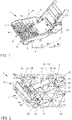
- FIG 1 shows a simplified perspective view of a vehicle seat 1 for a motor vehicle not shown here.
- the vehicle seat 1 has a seat frame 2 which can be fastened, for example, to a floor of a motor vehicle.
- the seat frame carries a seat part 3 and a backrest 4, which in the present embodiment without Seat covers or upholstery are shown.
- the seat part 3 has a seat pan 5 which serves as a support for the upholstery and which is pivotably mounted about a horizontal axis 6 at an end facing the backrest 4 .
- the seat part 3 is between a sitting position as shown in figure 1 shown, and pivotable to a raised set-up position, as indicated by arrow 7 in figure 1 displayed.
- a storage compartment 8 is also arranged on the seat frame 2 and is located in particular below the seat part 3 . An access opening to the storage compartment 8 is through the seat part 3 in figure 1 shown seating position covered. In order to access the storage compartment 8, the seat part 3 must be pivoted into the raised position so that the storage compartment 8 is released.
- the seat part 3 normally remains in the seated position, it has a locking device 9 which is arranged on the seat pan 5 .
- figure 2 shows the locking device 9 in an enlarged plan view of the seat part 3.
- the seat pan 5 is advantageously made at least essentially of plastic and has on its upper side a support structure made up of vertically aligned support walls 10 that run at least essentially in a straight line across the surface and are multiply , for example crosswise, star-like or diamond-shaped.
- the locking device 9 is slipped onto these supporting walls 10 and connected to it in a form-fitting manner to hold it.
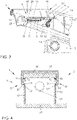
- figure 3 shows a simplified side view of the vehicle seat 1 in the area of the locking device 9 in order to explain its structure and function in more detail.
- the locking device 9 has a displaceable locking element 11 which, according to the present exemplary embodiment, is designed as a pivotable locking hook 12 .
- the locking hook 12 preferably has a pivot pin 12', which is inserted on both sides of the locking hook 12 in open-edged recesses 12" in supporting walls 10 arranged opposite one another so that it can pivot to ensure an advantageous rotational movement with little wear and little play.
- the locking hook 12 is designed to interact with a bracket element 13, which is fastened to the seat frame 2.
- the locking hook 12 has a locking position that engages behind the bracket element 13 and a locking position that engages the bracket element 13 In the locking position, the locking element 12 holds the locking device and thus the seat pan 5 in the sitting position lying storage compartment 8 release.
- the locking device 9 also has an actuating handle 14 which is pivotably mounted on the seat part 2 .
- the actuating handle 14 and the locking hook 12 are each pivotable about a horizontal axis.
- the horizontal axes of the actuating handle 14 and the locking hook 12 are preferably aligned parallel to one another.
- the locking device 9 also has a slide 15 which is coupled to the actuating handle 14 at one end and interacts with the locking hook 12 at the other end.
- the slider 15 is coupled with the actuating handle 14 in such a form-fitting manner that it is always moved along with the actuating handle 14 .
- the slide 15 is connected at one end to the actuating handle 14 in a pivoting manner.
- the slide 15 is not positively coupled to the locking hook 12, but is operatively connected in such a way that it can only apply a compressive force to the locking hook 12 to move it to the release position.
- the slide 15 has a starting bevel 16 on its end facing the locking hook 12, which, when the slide 15 is moved in the direction of the locking hook 12, causes the locking hook 12 to be rotated into the release position, as shown in FIG figure 3 shown by a dashed representation of the locking hook 12 in the release position.
- the locking device 9 also has a return spring 17 which, according to the present exemplary embodiment, is designed as a tension spring.
- the restoring spring 17 is fastened to the seat pan 5 at one end and coupled to the slide 15 at the other end, so that the restoring spring 17 counteracts a displacement of the slide 15 in the direction of the locking hook 6 .
- the return spring 17 thus also acts on the actuating handle 14 in such a way that the force of the return spring 17 causes it to return to its in figure 3 shown starting position is pushed.
- the return spring 17 is fastened, for example, to a bearing pin 25 which is inserted in an open-edged bearing opening 26 in two support walls 10 of the seat pan 5, as shown in FIG Figures 3 and 2 shown.
- the slider 15 is movably mounted in a carrier 18 of the locking device 9 .
- FIG 4 a simplified sectional view through the locking device 9.
- the carrier 18 has a C-shaped profile, into which the slide 15 is inserted.
- the slider 15 has a width that corresponds closely to the clear width of the carrier 18, so that the slider 15 is advantageously guided laterally on the carrier 18 so that it is always moved straight.
- the slide 15 is located on its upper side on the underside of the Carrier 18 and rests on its underside on the top of two mutually parallel supporting walls 10 of the seat pan 5. The slider 15 is thus linearly guided by the seat pan 5 on the one hand and the carrier 18 on the other hand.
- the carrier 18 itself has a plurality of vertically aligned and elastically deformable latching means 19 which are arranged spaced apart from one another along its longitudinal extent on both sides.
- the latching means 19 are each designed as latching lugs 20 which can be elastically pushed outwards.
- the detents 20 each have a starting bevel 21 on their front side, through which detents 20 are automatically pushed outwards when they hit the respective support wall 15 .
- the support walls 10 themselves have latching openings 22 which are used to receive the latching lugs 20 in such a way that the latching lugs engage behind the supporting walls 10 at least in some areas and thereby ensure a positive locking of the carrier 18 on the supporting walls 10 .
- the carrier 18 can thus be locked on the seat pan 5 by a form-fitting latching by simply slipping it onto the support walls 10 of the seat pan.
- the actuating handle 14 has a pivot pin 23, as in FIG figure 2 shown, which is formed in two parts, each pivot pin 23 rests in a respective open-edged bearing recess 24 of two oppositely arranged supporting walls 10 of the seat pan 5, so that a pivot bearing is formed.
- the pivot bolt parts 23 are designed to be aligned with one another and, in particular, are designed in one piece with the actuating handle 14 .
- the actuating handle 14 is thus pivotably mounted on the seat pan 5 and is articulated to the slide 15 .
- the locking hook 12 is also preferably pivotably mounted on the carrier 18 in an articulated manner, so that the locking device 9 can be preassembled overall and can be fastened or is fastened to the seat part 2 by simply slipping it onto the support walls 10 of the seat pan 5 .
- This enables simple assembly and simple handling of the locking device 9.
- only a few parts are required, in particular the additional provision of screws or other fastening means is dispensed with, so that the number of parts is kept low.
- the seat pan 5 preferably also has a reinforcement sheet, in particular an organic sheet 27, which is bordered by the seat pan 5 at least in regions.
- a reinforcement sheet in particular an organic sheet 27, which is bordered by the seat pan 5 at least in regions.
- the seat pan 5 made of plastic is injection molded onto the organo sheet 27 so that the organo sheet 27 is advantageously integrated into the seat pan 5 .
Landscapes
- Engineering & Computer Science (AREA)
- Mechanical Engineering (AREA)
- Aviation & Aerospace Engineering (AREA)
- Transportation (AREA)
- Seats For Vehicles (AREA)
Description
- Die Erfindung betrifft einen Fahrzeugsitz für ein Kraftfahrzeug, mit einem Sitzgestell, an welchem ein Sitzteil gelagert ist und welches an einem Fahrzeugboden befestigbar oder befestigt ist, mit wenigstens einem einer Unterseite des Sitzteils zugeordneten Ablagefach, wobei das Sitzteil zwischen einer das Ablagefach verdeckenden Sitzposition und einer das Ablagefach freigebenden Aufstellposition verschwenkbar gelagert ist, und mit einer Verriegelungseinrichtung zum Verriegeln des Sitzteils in der Sitzposition, wobei die Verriegelungseinrichtung ein Verriegelungselement und einen Betätigungsgriff zum Bewegen des Verriegelungselements von einer das Sitzteil an dem Sitzgestell arretierenden Arretierstellung in eine das Sitzteil zum Verlagern in die Aufstellposition freigebende Freigabestellung aufweist.
- Fahrzeugsitze der eingangs genannten Art sind aus dem Stand der Technik bereits bekannt. So offenbart beispielsweise die Offenlegungsschrift
DE 10 2005 010 434 A1 einen Fahrzeugsitz mit den Merkmalen des Oberbegriffs des Anspruchs 1. Aus den OffenlegungsschriftenDE 10 2009 052 594 A1 ,DE 37 05 059 A1 undDE 102 38 838 A1 sind bereits Fahrzeugsitze mit aufstellbaren Sitzteilen bekannt. Aus der OffenlegungsschriftDE 10 2013 009 329 A1 ist ein Fahrzeugsitz bekannt, bei welchem das Staufach als Schublade unterhalb eines Sitzteils ausgebildet ist. - Ein gattungsgemäßer Fahrzeugsitz ist auch aus der Offenlegungsschrift
DE 10 2017 119 713 A1 bekannt. Weiterhin offenbart die PatentschriftDE 10 2010 042 881 B4 einen Fahrzeugsitz ohne Ablagefach, der eine verrastbare Betätigungseinrichtung für eine Schenkelstütze aufweist. - Der Erfindung liegt die Aufgabe zugrunde, einen verbesserten Fahrzeugsitz zu schaffen, der eine einfache Montage und eine sichere Arretierung des Sitzteils in der Sitzposition gewährleistet.
- Die der Erfindung zugrundeliegende Aufgabe wird durch einen Fahrzeugsitz mit den Merkmalen des Anspruchs 1 gelöst. Dieser hat den Vorteil, dass die Verriegelungseinrichtung einfach montierbar ist und einen sicheren Halt des Sitzteils an dem Sitzgestell gewährleistet. Dabei ist die Verriegelungseinrichtung selbst kostengünstig realisierbar und mit wenigen Einzelteilen darstellbar. Erfindungsgemäß ist dazu vorgesehen, dass die Verriegelungseinrichtung an einer Sitzwanne des Sitzteils formschlüssig verrastet ist. Die Verriegelungseinrichtung ist also durch eine Verrastung an dem Sitzteil beziehungsweise an dessen Sitzwanne gehalten. Durch die Verrastung ist eine einfache Montage ermöglicht, die insbesondere ohne zusätzliche Befestigungsmittel erfolgen kann. Die beispielsweise vormontierte Verriegelungseinrichtung wird dazu zur Montage an der Sitzwanne einfach an diese herangeführt und verrastet, ohne dass nachträglich eine Verschraubung, Vernietung oder dergleichen vorgenommen werden muss. Dadurch wird die Anzahl der Einzelteile für den Fahrzeugsitz reduziert und die Montage vereinfacht. Durch die Verrastung, die einen formschlüssigen Sitz der Verriegelungsanordnung an der Sitzwanne gewährleistet, ist außerdem eine feste Verbindung zwischen Verriegelungseinrichtung und Sitzwanne gewährleistet, welche robust ist und eine hohe Lebensdauer gewährleistet.
- Gemäß einer bevorzugten Weiterbildung der Erfindung ist die Verriegelungseinrichtung nur durch zumindest bereichsweise elastisch verformbare Rastmittel an der Sitzwanne befestigt. Durch die elastische Verformbarkeit der Rastmittel ist ein Aufstecken oder Anstecken der Verriegelungseinrichtung, insbesondere ein Anklipsen der Verriegelungseinrichtung an die Sitzwanne ohne weitere Hilfsmittel möglich. Durch die Eigenelastizität der Rastmittel schnappen diese in eine die Sitzwanne formschlüssig greifende, insbesondere hintergreifende, Position, in welcher die Verriegelungseinrichtung dann formschlüssig an der Sitzwanne gehalten ist. Insbesondere sind die elastisch verformbaren Rastmittel als elastisch verlagerbare Rastnasen ausgebildet, die mit Rastöffnungen der Sitzwanne und/oder der Verriegelungseinrichtung zusammenwirken. Die Rastmittel können grundsätzlich an der Verriegelungseinrichtung und/oder an der Sitzwanne ausgebildet oder befestigt sein. Vorzugsweise sind die Rastmittel einstückig mit der Sitzwanne oder einem Bestandteil der Verriegelungseinrichtung ausgebildet.
- Erfindungsgemäß weist die Sitzwanne mehrere Stützwände auf, welche in die Verriegelungseinrichtung aufgesteckt oder aufgelegt ist. Durch die Stützwände ist eine einfache Anordnung der Verriegelungseinrichtung an der Sitzwanne gewährleistet. Insbesondere sind die Stützwände derart ausgebildet, dass sie eine versteifende Stützstruktur für die Sitzwanne ausbilden. Dazu erstrecken sich die Stützwände beispielsweise geradlinig entlang einer Oberseite oder Unterseite der Sitzwanne derart, dass sie sich sternförmig und/oder rautenförmig kreuzen. In dem Bereich, in welchem die Verriegelungseinrichtung angeordnet ist, sind die Stützwände bevorzugt verkürzt ausgebildet, sodass die Verriegelungseinrichtung in die Sitzwanne integrierbar ist, sodass sie zumindest im Wesentlichen in die Sitzwanne eingebettet ist, und insbesondere nicht über die übrigen Stützwände hinaus vorsteht.
- Weiterhin ist bevorzugt vorgesehen, dass der Betätigungsgriff einen Drehbolzen aufweist, der in einer randoffenen Laderöffnung von zumindest zwei einander gegenüberliegend angeordneten Stützwänden drehbar gelagert ist. Die Drehlagerung des Betätigungsgriffs wird somit durch die Stützwände selbst mitgebildet, sodass auch hier die Teilezahl reduziert wird. Durch die randoffene Ausbildung der Lageröffnung ist ein einfaches Einlegen des Drehbolzens in die Lageröffnung gewährleistet. Der Drehbolzen des Betätigungsgriffs kann dabei einteilig oder zweiteilig ausgebildet sein, wobei bei einer zweiteiligen Ausbildung die Drehbolzenteile getrennt beziehungsweise beabstandet voneinander vorliegen können, jedoch fluchtend zueinander ausgerichtet sind.
- Weiterhin ist bevorzugt vorgesehen, dass die Verriegelungseinrichtung einen Träger aufweist, der auf mehreren der Stützwände direkt oder indirekt aufliegt und einen Schieber lagert, der mit dem Betätigungsgriff einerseits und mit dem Verriegelungselement andererseits wirkverbunden ist. Der Betätigungsgriff und Verriegelungselement miteinander verbindende Schieber ist also an oder in einem Träger der Verriegelungseinrichtung gelagert, wobei der Träger auf den Stützwänden aufliegt. Damit liegt der Träger bevorzugt zumindest bereichsweise direkt auf den Stützwänden auf oder indirekt und insbesondere unter Zwischenschaltung des Schiebers, sodass der Schieber zwischen dem Träger und den Stützwänden geführt ist. Besonders bevorzugt sind die zuvor erwähnten Rastmittel an dem Träger insbesondere einstückig ausgebildet, sodass über den Träger die Arretierung der Verriegelungseinrichtung an der Sitzwanne realisiert oder mitrealisiert ist. Durch den Träger ist eine sichere Führung des Schiebers und damit eine sichere Betätigung des Betätigungsgriffs gewährleistet. Vorzugsweise sind an dem Träger auch der Betätigungsgriff und/oder das Verriegelungselement gehalten, sodass der Träger zusammen mit diesen eine Vormontagebaugruppe der Verriegelungseinrichtung bildet, die eine einfache Montage an dem Sitzteil gewährleistet.
- Vorzugsweise bildet der Träger eine Schienenführung für den Schieber, beispielsweise zusammen mit der Sitzwanne. Durch die Schienenführung wird eine Linearführung für den Schieber geboten, die eine sichere Betätigung des Verriegelungselements durch den Betätigungsgriff gewährleistet.
- Vorzugsweise ist der Schieber zwischen dem Träger einerseits und der Sitzwanne andererseits verschiebbar geführt, wie vorstehend bereits erwähnt. Dadurch ergibt sich, dass der Schieber sicher zwischen Träger und Sitzwanne gehalten ist. Alternativ ist der Schieber allein an dem Träger geführt, wodurch der Träger dann die Schienenführung für den Schieber alleine ausbildet, beispielsweise indem er ein C-förmiges Querschnittsprofil aufweist, in welches der Schieber eingeschoben ist.
- Gemäß einer bevorzugten Weiterbildung der Erfindung weist der Träger mehrere elastisch verformbare Rastnasen als Rastmittel auf, die in Rastöffnungen der Sitzwanne, insbesondere Stützwanne eingreifen. Dadurch ergibt sich ein einfaches Anklipsen des Trägers an die Sitzwanne, wie vorstehend bereits erwähnt. Durch das Vorsehen der Rastmittel an dem Träger und der Rastöffnungen an der Sitzwanne ist eine einfache Gestaltung von Träger und Sitzwanne möglich, die eine kostengünstige Herstellung des Fahrzeugsitzes ermöglicht.
- Weiterhin ist bevorzugt vorgesehen, dass das Verriegelungselement ein Verriegelungshaken ist, der dazu ausgebildet ist, mit einem an dem Sitzgestell befestigten Sitzbügel in der Arretierstellung zusammenzuwirken, wobei der Verriegelungshaken durch den Betätigungsgriff und den Schieber in die Freigabestellung verschwenkbar ist. Der verschwenkbare Verriegelungshaken wird somit durch die Betätigung des Betätigungsgriffs bedient, um von der Arretierstellung in die Freigabestellung verschwenkt zu werden. Durch den Verriegelungshaken ist ein vorteilhaftes Hintergreifen des Sitzbügels geboten, das einen sicheren Halt des Sitzteils in der Sitzposition gewährleistet.
- Bevorzugt ist der Verriegelungshaken durch den Schieber nur mit einer Druckkraft beaufschlagbar. Dadurch ergibt sich, dass der Verriegelungshaken auch unabhängig von dem Schieber in die Freigabestellung verschwenkbar ist. Dies ist insbesondere dann von Vorteil, wenn das Sitzteil von der Aufstellposition in die Sitzposition verschwenkt wird. Durch die vorteilhafte Ausbildung ist der Verriegelungshaken unabhängig von einem Schieber in die Freigabestellung verschwenkbar, sodass er insbesondere auch eine entsprechende Formgebung durch den Sitzbügel beim Verschwenken des Sitzteils in die Sitzposition automatisch in die Freigabestellung verschoben wird, um anschließend den Sitzbügel wieder zu hintergreifen.
- Bevorzugt weist die Verriegelungseinrichtung zumindest eine Rückstellfeder auf, die einer Betätigung des Betätigungsgriffs entgegenwirkt. Dadurch ist ein ungewolltes Lösen der Verriegelung einfach verhindert. Darüber hinaus wird der Vorteil erreicht, dass der Betätigungsgriff durch die Rückstellfeder in seine Ausgangsstellung zurückgelangt und die Verriegelung sicherstellt.
- Gemäß einer bevorzugten Weiterbildung der Erfindung ist die Rückstellfeder an der Sitzwanne einerseits und an einem von dem Betätigungsgriff abgewandten Ende des Schiebers andererseits befestigt und als Zugfeder ausgebildet. Durch die Zugkraft zieht die Rückstellfeder den Betätigungsgriff vorteilhafterweise in seine Ausgangsposition und zwar unabhängig von der Stellung des Verriegelungshakens. Dazu ist das andere Ende der Rückstellfeder an dem Schieber und nicht an dem Haken befestigt. Dadurch wird die zuvor beschriebene Funktion, der automatischen Verlagerung des Verriegelungshakens in die Freigabestellung beim Verschwenken des Sitzteils in die Sitzposition weiter gewährleistet.
- Besonders bevorzugt ist die Sitzwanne mit den Stützwänden aus Kunststoff gefertigt und insbesondere einstückig mit diesen ausgebildet. Dadurch ergibt sich eine einfache und kostengünstige Herstellung der Sitzwanne.
- Vorzugsweise ist an der Sitzwanne zumindest ein Verstärkungsblech, insbesondere ein Organoblech, zur Verstärkung der Kunststoffsitzwanne angeordnet. Hierdurch weist die Sitzwanne zum einen ein geringes Gewicht auf und ist zum anderen robust und belastbar.
- Besonders bevorzugt ist die Sitzwanne an das Organoblech angespritzt, sodass das Organoblech vorteilhaft in den Kunststoff der Sitzwanne integriert ist, wodurch sich eine besonders feste Verbindung zwischen Sitzwanne und Organoblech ergibt.
- Im Folgenden soll die Erfindung anhand der Zeichnungen näher erläutert werden. Dazu zeigen
- Figur 1
- einen Fahrzeugsitz für ein Kraftfahrzeug in einer vereinfachten Darstellung,
- Figur 2
- eine vergrößerte Draufsicht auf den Fahrzeugsitz,
- Figur 3
- eine schematische Seitenansicht und
- Figur 4
- eine Schnittdarstellung durch den Fahrzeugsitz.
-
Figur 1 zeigt in einer vereinfachten perspektivischen Darstellung einen Fahrzeugsitz 1 für ein hier nicht näher dargestelltes Kraftfahrzeug. Der Fahrzeugsitz 1 weist ein Sitzgestell 2 auf, das beispielsweise an einem Boden eines Kraftfahrzeugs befestigbar ist. Das Sitzgestell trägt ein Sitzteil 3 sowie eine Rückenlehne 4, die in dem vorliegenden Ausführungsbeispiel ohne Sitzbezüge oder -polster dargestellt sind. Das Sitzteil 3 weist eine Sitzwanne 5 auf, die als Träger für die Bepolsterung dient, und welche an einem der Rückenlehne 4 zugewandten Ende um eine Horizontalachse 6 verschwenkbar gelagert ist. Dabei ist das Sitzteil 3 zwischen einer Sitzposition, wie sie inFigur 1 gezeigt ist, und einer hochgestellten Aufstellposition verschwenkbar, wie durch einen Pfeil 7 inFigur 1 angezeigt. An dem Sitzgestell 2 ist außerdem ein Ablagefach 8 angeordnet, das sich insbesondere unterhalb des Sitzteils 3 befindet. Eine Zugangsöffnung zu dem Ablagefach 8 wird durch das Sitzteil 3 in der inFigur 1 gezeigten Sitzposition verdeckt. Um an das Ablagefach 8 zu gelangen, ist das Sitzteil 3 in die Aufstellposition zu verschwenken, sodass das Ablagefach 8 freigegeben ist. - Damit das Sitzteil 3 im Normalfall in der Sitzposition verbleibt, weist es eine Verriegelungseinrichtung 9 auf, die an der Sitzwanne 5 angeordnet ist.
Figur 2 zeigt hierzu in einer vergrößerten Draufsicht auf das Sitzteil 3 die Verriegelungseinrichtung 9. Die Sitzwanne 5 ist vorteilhafterweise zumindest im Wesentlichen aus Kunststoff gefertigt und weist an ihrer Oberseite eine Stützstruktur aus zumindest im Wesentlichen gradlinig über die Oberfläche verlaufenden und vertikal ausgerichteten Stützwände 10, die sich mehrfach, beispielsweise kreuzweise, sternartig oder rautenförmig kreuzen. Auf diese Stützwände 10 ist die Verriegelungseinrichtung 9 aufgesteckt und formschlüssig zu ihrer Halterung damit verbunden. -
Figur 3 zeigt eine vereinfachte Seitenansicht des Fahrzeugsitzes 1 im Bereich der Verriegelungseinrichtung 9, um deren Aufbau und Funktion näher zu erläutern. - Die Verriegelungseinrichtung 9 weist ein verlagerbares Verriegelungselement 11 auf, das gemäß dem vorliegenden Ausführungsbeispiel als verschwenkbarer Verriegelungshaken 12 ausgebildet ist. Der Verriegelungshaken 12 weist dabei bevorzugt einen Drehbolzen 12' auf, der beidseits des Verriegelungshakens 12 in randoffenen Aussparungen 12" voneinander gegenüberliegend angeordneten Stützwänden 10 verschwenkbar eingelegt ist. Dazu weisen die Aussparungen bevorzugt jeweils einen an den Drehbolzen 12' angepasst gekrümmten Boden auf, um eine vorteilhafte Drehbewegung mit geringem Verschleiß und geringem Spiel zu gewährleisten. Der Verriegelungshaken 12 ist dazu ausgebildet, mit einem Bügelelement 13, das an dem Sitzgestell 2 befestigt ist, zusammenzuwirken. Dazu ist der Verriegelungshaken 12 von einer das Bügelelement 13 hintergreifenden Arretierstellung und einer das Bügelelement 13 freigebenden Freigabestellung verschwenkbar. In der Arretierstellung hält das Verriegelungselement 12 die Verriegelungseinrichtung und damit die Sitzwanne 5 in der Sitzposition. In der Freigabestellung ist ein Anheben des Sitzteils 3 auf der von der Rückenlehne abgewandten Ende möglich, um das darunterliegende Ablagefach 8 freizugeben. Die Verriegelungseinrichtung 9 weist weiterhin ein Betätigungsgriff 14 auf, der verschwenkbar an dem Sitzteil 2 gelagert ist. Insbesondere sind der Betätigungsgriff 14 und der Verriegelungshaken 12 jeweils um eine horizontale Achse verschwenkbar. Vorzugsweise sind die Horizontalachsen von Betätigungsgriff 14 und Verriegelungshaken 12 parallel zueinander ausgerichtet.
- Die Verriegelungseinrichtung 9 weist weiterhin einen Schieber 15 auf, der einendig mit dem Betätigungsgriff 14 gekoppelt ist und anderendig mit dem Verriegelungshaken 12 zusammenwirkt. Dabei ist der Schieber 15 mit dem Betätigungsgriff 14 derart formschlüssig gekoppelt, dass er stets mit dem Betätigungsgriff 14 mitbewegt wird. Dazu ist der Schieber 15 einendig schwenkgelenkig mit dem Betätigungsgriff 14 verbunden. Mit dem Verriegelungshaken 12 ist der Schieber 15 hingegen nicht zwangsgeführt gekoppelt, sondern derart wirkverbunden, dass er lediglich eine Druckkraft auf den Verriegelungshaken 12 zu dessen Verlagerung an die Freigabestellung aufbringen kann. Dazu weist der Schieber 15 an seinem dem Verriegelungshaken 12 zugewandten Ende eine Anlaufschräge 16 auf, welche beim Verlagern des Schiebers 15 in Richtung des Verriegelungshakens 12 dazu führt, dass der Verriegelungshaken 12 in die Freigabestellung verdreht wird, wie in
Figur 3 durch eine gestrichelte Darstellung des Verriegelungshakens 12 in der Freigabestellung gezeigt. - Die Verriegelungseinrichtung 9 weist weiterhin eine Rückstellfeder 17 auf, die gemäß dem vorliegenden Ausführungsbeispiel als Zugfeder ausgebildet ist. Die Rückstellfeder 17 ist einendig an der Sitzwanne 5 befestigt und anderendig mit dem Schieber 15 gekoppelt, sodass die Rückstellfeder 17 einem Verschieben des Schiebers 15 in Richtung des Verriegelungshakens 6 entgegenwirkt. Damit wirkt die Rückstellfeder 17 auch auf den Betätigungsgriff 14 derart, dass dieser durch die Kraft der Rückstellfeder 17 in seine in
Figur 3 gezeigte Ausgangsstellung gedrängt wird. Die Rückstellfeder 17 ist dabei beispielsweise an einem Lagerbolzen 25 befestigt, der jeweils in einer randoffenen Lageröffnung 26 von zwei Stützwänden 10 der Sitzwanne 5 eingelegt ist, wie inFiguren 3 und2 gezeigt. - Der Schieber 15 ist in einem Träger 18 der Verriegelungseinrichtung 9 verschiebbar gelagert. Hierzu zeigt
Figur 4 eine vereinfachte Schnittdarstellung durch die Verriegelungseinrichtung 9. Der Träger 18 weist ein C-förmiges Profil auf, in welches der Schieber 15 eingeschoben ist. Dabei weist der Schieber 15 eine Breite auf, die nahe zu der lichten Weite des Trägers 18 entspricht, sodass der Schieber 15 seitlich an dem Träger 18 vorteilhaft geführt ist, dass er stets gerade bewegt wird. Vorliegend liegt der Schieber 15 an seiner Oberseite an der Unterseite des Trägers 18 an und liegt an seiner Unterseite auf der Oberseite von zwei parallel zueinander ausgerichteten Stützwänden 10 der Sitzwanne 5 auf. Damit ist der Schieber 15 durch die Sitzwanne 5 einerseits und den Träger 18 andererseits linear geführt. - Der Träger 18 selbst weist mehrere vertikal ausgerichtete und elastisch verformbare Rastmittel 19 auf, die beidseitig entlang seiner Längserstreckung beabstandet zueinander verteilt angeordnet sind. Die Rastmittel 19 sind jeweils als Rastnasen 20 ausgebildet, die elastisch nach außen gedrängt werden können. Die Rastnasen 20 weisen an ihrer Frontseite jeweils eine Anlaufschräge 21 auf, durch welche Rastnasen 20 automatisch nach außen gedrängt werden, wenn sie auf die jeweilige Stützwand 15 treffen. Die Stützwände 10 weisen selbst Rastöffnungen 22 auf, die dazu dienen, die Rastnasen 20 derart aufzunehmen, dass die Rastnasen die Stützwände 10 zumindest bereichsweise hintergreifen und dadurch eine formschlüssige Arretierung des Trägers 18 an den Stützwänden 10 gewährleisten. Der Träger 18 ist somit durch ein einfaches Aufstecken auf die Stützwände 10 der Sitzwanne 5 an dieser durch eine formschlüssige Verrastung arretierbar.
- Der Betätigungsgriff 14 weist einen Drehbolzen 23 auf, wie in
Figur 2 gezeigt, der zweiteilig ausgebildet ist, wobei jeder Drehbolzen 23 in jeweils einer randoffenen Lageraussparung 24 von zwei einander gegenüberliegend angeordneten Stützwänden 10 der Sitzwanne 5 einliegt, sodass ein Drehlager gebildet ist. Die Drehbolzenteile 23 sind dazu fluchtend miteinander ausgebildet und insbesondere einstückig mit dem Betätigungsgriff 14 ausgebildet. Der Betätigungsgriff 14 ist somit an der Sitzwanne 5 verschwenkbar gelagert und mit dem Schieber 15 gelenkig gekoppelt. Auch der Verriegelungshaken 12 ist bevorzugt gelenkig an dem Träger 18 verschwenkbar gelagert, sodass die Verriegelungseinrichtung 9 insgesamt vormontierbar ist und durch ein einfaches Aufstecken auf die Stützwände 10 der Sitzwanne 5 an dem Sitzteil 2 befestigbar beziehungsweise befestigt ist. Dadurch ist eine einfache Montage sowie eine einfache Handhabung der Verriegelungseinrichtung 9. Zudem werden nur wenige Teile benötigt, insbesondere wird auf das zusätzliche Vorsehen von Schrauben oder andere Befestigungsmittel verzichtet, sodass die Teilezahl geringgehalten wird. - Zur Verstärkung der Sitzwanne 5 weist diese bevorzugt außerdem ein Verstärkungsblech, insbesondere ein Organoblech 27 auf, das von der Sitzwanne 5 zumindest bereichsweise eingefasst ist. Insbesondere ist die aus Kunststoff gefertigte Sitzwanne 5 an das Organoblech 27 angespritzt, sodass das Organoblech 27 vorteilhaft in die Sitzwanne 5 integriert ist.
-
- 1
- Fahrzeugsitz
- 2
- Sitzgestell
- 3
- Sitzteil
- 4
- Rückenlehne
- 5
- Sitzwanne
- 6
- Horizontalachse
- 7
- Pfeil
- 8
- Ablagefach
- 9
- Verriegelungseinrichtung
- 10
- Stützwand
- 11
- Verriegelungselement
- 12
- Verriegelungshaken
- 12'
- Drehbolzen
- 12"
- Aussparung
- 13
- Bügelelement
- 14
- Betätigungsgriff
- 15
- Schieber
- 16
- Anlaufschräge
- 17
- Rückstellfeder
- 18
- Träger
- 19
- Rastmittel
- 20
- Rastnase
- 21
- Anlaufschräge
- 22
- Rastöffnung
- 23
- Drehbolzen
- 24
- Lageraussparung
- 25
- Lagerbolzen
- 26
- Lageröffnung
- 27
- Organoblech
Claims (14)
- Fahrzeugsitz (1) für ein Kraftfahrzeug, mit einem Sitzgestell (2), an welchem ein Sitzteil (3) gelagert ist und welches an einem Fahrzeugboden befestigbar oder befestigt ist, mit wenigstens einem einer Unterseite des Sitzteils (3) zugeordneten Ablagefach, wobei das Sitzteil (3) zwischen einer das Ablagefach (8) verdeckenden Sitzposition und einer das Ablagefach (8) freigebenden Aufstellposition verschwenkbar gelagert ist, und mit einer Verriegelungseinrichtung (9) zum Verriegeln des Sitzteils (3) in der Sitzposition, wobei die Verriegelungseinrichtung (9) ein Verriegelungselement (11) und einen Betätigungsgriff (14) zum Bewegen des Verriegelungselements (11) von einer das Sitzteil (3) an dem Sitzgestell (2) arretierenden Arretierstellung in eine das Sitzteil (3) zum Verlagern freigebende Freigabestellung aufweist, dadurch gekennzeichnet, dass das Sitzteil (3) eine Sitzwanne (5) aufweist, wobei die Verriegelungseinrichtung (9) an der Sitzwanne (5) formschlüssig verrastet ist, und dass die Sitzwanne (5) mehrere Stützwände (10) aufweist, auf welche die Verriegelungseinrichtung (9) aufgesteckt oder aufgelegt ist.
- Fahrzeugsitz nach Anspruch 1, dadurch gekennzeichnet, dass die Verriegelungseinrichtung (9) nur durch zumindest bereichsweise elastisch verformbare Rastmittel (19) an der Sitzwanne (5) befestigt ist.
- Fahrzeugsitz nach einem der vorhergehenden Ansprüche, dadurch gekennzeichnet, dass der Betätigungsgriff (14) einen Drehbolzen (23) aufweist, der in einer randoffenen Lageröffnung von zumindest zwei einander gegenüberliegend angeordneten Stützwänden (10) drehbar gelagert ist.
- Fahrzeugsitz nach einem der vorhergehenden Ansprüche, dadurch gekennzeichnet, dass die Verriegelungseinrichtung (9) einen Träger (18) aufweist, der auf mehreren der Stützwände (10) direkt oder indirekt aufliegt und einen Schieber (15) lagert, der mit dem Betätigungsgriff (14) einerseits und mit dem Verriegelungselement (11) andererseits wirkverbunden ist.
- Fahrzeugsitz nach Anspruch 4, dadurch gekennzeichnet, dass der Träger (18) eine Schienenführung für den Schieber (15) bildet.
- Fahrzeugsitz nach Anspruch 4 oder 5, dadurch gekennzeichnet, dass der Schieber (15) zwischen dem Träger (18) einerseits und der Sitzwanne (5) andererseits verschiebbar geführt ist.
- Fahrzeugsitz nach einem der Ansprüche 4 bis 6, dadurch gekennzeichnet, dass der Träger (18) mehrere elastisch verformbare Rastnasen (20) als Rastmittel (19) aufweist, die in Rastöffnungen (22) der Sitzwanne (5), insbesondere der Stützwände (10), eingreifen.
- Fahrzeugsitz nach einem der Ansprüche 4 bis 7, dadurch gekennzeichnet, dass das Verriegelungselement (9) ein Verriegelungshaken (12) ist, der dazu ausgebildet ist, mit einem an dem Sitzgestell (2) befestigten Sitzbügel (13) zusammenzuwirken, wobei der Verriegelungshaken (12) durch den Betätigungsgriff (14) und den Schieber (15) in die Freigabestellung verschwenkbar ist.
- Fahrzeugsitz nach Anspruch 8, dadurch gekennzeichnet, dass der Verriegelungshaken (12) durch den Schieber (15) nur mit einer Druckkraft beaufschlagbar ist.
- Fahrzeugsitz nach einem der vorhergehenden Ansprüche, dadurch gekennzeichnet, dass die Verriegelungseinrichtung (9) zumindest eine Rückstellfeder (17) aufweist, die einer Betätigung des Betätigungsgriffs (14) entgegenwirkt.
- Fahrzeugsitz nach einem der Ansprüche 4 bis 10, dadurch gekennzeichnet, dass die Rückstellfeder (17) an der Sitzwanne (5) einerseits und an einem von dem Betätigungsgriff (14) abgewandten Ende des Schiebers (15) andererseits befestigt und als Zugfeder ausgebildet ist.
- Fahrzeugsitz nach einem der vorhergehenden Ansprüche, dadurch gekennzeichnet, dass die Sitzwanne (5) insbesondere einstückig mit den Stützwänden (10) aus Kunststoff gefertigt ist.
- Fahrzeugsitz nach einem der vorhergehenden Ansprüche, dadurch gekennzeichnet, dass an der Sitzwanne (5) zumindest ein Verstärkungsblech, insbesondere Organoblech (27), angeordnet ist.
- Fahrzeugsitz nach Anspruch 13, dadurch gekennzeichnet, dass die Sitzwanne (5) an das Organoblech (27) angespritzt ist.
Applications Claiming Priority (1)
| Application Number | Priority Date | Filing Date | Title |
|---|---|---|---|
| DE102019205421.8A DE102019205421A1 (de) | 2019-04-15 | 2019-04-15 | Fahrzeugsitz für ein Kraftfahrzeug |
Publications (2)
| Publication Number | Publication Date |
|---|---|
| EP3725588A1 EP3725588A1 (de) | 2020-10-21 |
| EP3725588B1 true EP3725588B1 (de) | 2022-10-05 |
Family
ID=70227782
Family Applications (1)
| Application Number | Title | Priority Date | Filing Date |
|---|---|---|---|
| EP20168347.1A Active EP3725588B1 (de) | 2019-04-15 | 2020-04-07 | Fahrzeugsitz für ein kraftfahrzeug |
Country Status (2)
| Country | Link |
|---|---|
| EP (1) | EP3725588B1 (de) |
| DE (1) | DE102019205421A1 (de) |
Citations (1)
| Publication number | Priority date | Publication date | Assignee | Title |
|---|---|---|---|---|
| DE102010042881A1 (de) * | 2010-10-25 | 2012-04-26 | Brose Fahrzeugteile Gmbh & Co. Kommanditgesellschaft, Coburg | Fahrzeugsitz mit einer Sitztiefenverstelleinrichtung |
Family Cites Families (11)
| Publication number | Priority date | Publication date | Assignee | Title |
|---|---|---|---|---|
| DE3705059C2 (de) * | 1987-02-18 | 1993-11-18 | Daimler Benz Ag | Sitz für Fahrzeuge, insbesondere Rücksitz |
| TW590805B (en) * | 2001-09-28 | 2004-06-11 | Primax Electronics Ltd | Spiral cutter and its assembling method |
| DE102005010434B4 (de) * | 2005-03-08 | 2009-02-05 | Daimler Ag | Fahrzeug |
| US7523985B2 (en) * | 2006-02-06 | 2009-04-28 | Toyota Motor Engineering & Manufacturing North America, Inc. | Seat assembly having integrated belt, storage compartments and registers |
| DE202006019341U1 (de) * | 2006-12-20 | 2007-03-01 | Decoma (Germany) Gmbh | Organoblechstrukturbauteil |
| DE102009040901B4 (de) * | 2009-09-11 | 2022-02-24 | Brose Fahrzeugteile SE & Co. Kommanditgesellschaft, Coburg | Verfahren zum Herstellen von Tragstrukturen in Kraftfahrzeugen |
| DE102009052594A1 (de) * | 2009-11-10 | 2011-05-12 | GM Global Technology Operations LLC, Detroit | Verfahren und Kopplungseinrichtung zum verstauen eines Kraftfahrzeugsitzes |
| DE102013009329A1 (de) * | 2013-06-03 | 2014-12-04 | Volkswagen Aktiengesellschaft | Fahrzeugsitz oder Sitzbank, insbesondere Doppelsitzbank mit einem verschiebbaren Staufach mit Durchladefunktion |
| US9802546B2 (en) * | 2016-01-12 | 2017-10-31 | Ford Global Technologies, Llc | Under-seat vehicle compartment having a clamp assembly for engaging a tube support and for absorbing tolerances and movement related noise |
| US10086766B2 (en) * | 2016-08-30 | 2018-10-02 | Ford Global Technologies, Llc | Structural composite seat cushion frame and storage lid with lockable latch system |
| DE102016124515A1 (de) * | 2016-12-15 | 2018-06-21 | Kokinetics Gmbh | Trägerplatte und Grundplatte für einen Sitztiefenversteller, Sitztiefenversteller und Fahrzeugsitz |
-
2019
- 2019-04-15 DE DE102019205421.8A patent/DE102019205421A1/de not_active Withdrawn
-
2020
- 2020-04-07 EP EP20168347.1A patent/EP3725588B1/de active Active
Patent Citations (1)
| Publication number | Priority date | Publication date | Assignee | Title |
|---|---|---|---|---|
| DE102010042881A1 (de) * | 2010-10-25 | 2012-04-26 | Brose Fahrzeugteile Gmbh & Co. Kommanditgesellschaft, Coburg | Fahrzeugsitz mit einer Sitztiefenverstelleinrichtung |
Also Published As
| Publication number | Publication date |
|---|---|
| DE102019205421A1 (de) | 2020-10-15 |
| EP3725588A1 (de) | 2020-10-21 |
Similar Documents
| Publication | Publication Date | Title |
|---|---|---|
| DE69816254T2 (de) | Fahrzeugsitzeinheit mit auf Gleitschienen montiertem, abnehmbarem Sitz | |
| EP2271514B1 (de) | Betätigungseinheit eines kraftfahrzeugsitzes | |
| DE102013214175A1 (de) | Längseinstellbarer fahrzeugsitz | |
| DE102010055244A1 (de) | Längseinstellbarer Fahrzeugsitz | |
| DE102019135374B4 (de) | Schiene für einen Fahrzeugsitz und Fahrzeugsitz mit einer derartigen Schiene | |
| DE602004009270T2 (de) | Eine höhenverstellbare Armlehne für eine Kraftfahrzeugtür | |
| DE102020128572A1 (de) | Laufschiene für einen Fahrzeugsitz und Fahrzeugsitz mit einer solchen Laufschiene | |
| DE102013003867B4 (de) | Fahrzeugsitz umfassend eine Sitzflächenverlängerung | |
| EP2729364A1 (de) | Armlehnenvorrichtung für einen fahrzeugsitz | |
| EP1107878B1 (de) | Befestigungsvorrichtung für einen kindersitz | |
| EP3380360B1 (de) | Sitztiefenversteller | |
| DE102011121703A1 (de) | Gleitschienenanordnung für einen Fahrzeugsitz und Fahrzeugsitz umfassend eine solche Gleitschienenanordnung | |
| DE10236582A1 (de) | Beweglicher Behälter für den Einbau in Kraftwagen, wie Mittelkonsolbehälter o. dgl. | |
| EP2289387B1 (de) | Geschirrspülmaschine, insbesondere Haushaltsgeschirrspülmaschine | |
| DE102009009139A1 (de) | Mittelarmlehne für ein Kraftfahrzeug | |
| EP3725588B1 (de) | Fahrzeugsitz für ein kraftfahrzeug | |
| DE102006039505B4 (de) | Manuell längsverstellbarer Kraftfahrzeugsitz | |
| EP0893306B1 (de) | Kofferraum-Einrichtung für den Einbau in Kraftfahrzeuge, insbesondere für den sitzlehnenseitigen Einbau in Personenkraftwagen | |
| DE10144065B4 (de) | Anordnung zur Befestigung eines Funktionselementes in einem Fahrzeug | |
| DE102012219206B4 (de) | Dorsokinetische Rückenlehne eines Sitzmöbels, Sitzmöbel | |
| EP2388169B1 (de) | Betätigungsvorrichtung für eine Feststellbremse | |
| DE10034019B4 (de) | Befestigungsvorrichtung, insbesondere für einen Fahrzeugsitz | |
| EP3085577A1 (de) | Polsterintegriertes bedienelement | |
| DE102009019188A1 (de) | Verstelleinrichtung für die Höhenverstellung, insbesondere für die Verstellung der Höhe von Sitzkissen von Fahrzeugsitzen für Kraftfahrzeuge | |
| DE102019216331A1 (de) | Sitztiefenverstelleinrichtung für einen Fahrzeugsitz |
Legal Events
| Date | Code | Title | Description |
|---|---|---|---|
| PUAI | Public reference made under article 153(3) epc to a published international application that has entered the european phase |
Free format text: ORIGINAL CODE: 0009012 |
|
| STAA | Information on the status of an ep patent application or granted ep patent |
Free format text: STATUS: THE APPLICATION HAS BEEN PUBLISHED |
|
| AK | Designated contracting states |
Kind code of ref document: A1 Designated state(s): AL AT BE BG CH CY CZ DE DK EE ES FI FR GB GR HR HU IE IS IT LI LT LU LV MC MK MT NL NO PL PT RO RS SE SI SK SM TR |
|
| AX | Request for extension of the european patent |
Extension state: BA ME |
|
| RIN1 | Information on inventor provided before grant (corrected) |
Inventor name: HARTMANN, STEPHAN Inventor name: PYATOV, NIKITA Inventor name: CAFARO, MIRNA Inventor name: LAHL, BENEDIKT Inventor name: WALTER, HELMUT Inventor name: BUSCH, CHRISTIAN |
|
| STAA | Information on the status of an ep patent application or granted ep patent |
Free format text: STATUS: REQUEST FOR EXAMINATION WAS MADE |
|
| 17P | Request for examination filed |
Effective date: 20210421 |
|
| RBV | Designated contracting states (corrected) |
Designated state(s): AL AT BE BG CH CY CZ DE DK EE ES FI FR GB GR HR HU IE IS IT LI LT LU LV MC MK MT NL NO PL PT RO RS SE SI SK SM TR |
|
| GRAP | Despatch of communication of intention to grant a patent |
Free format text: ORIGINAL CODE: EPIDOSNIGR1 |
|
| STAA | Information on the status of an ep patent application or granted ep patent |
Free format text: STATUS: GRANT OF PATENT IS INTENDED |
|
| RIC1 | Information provided on ipc code assigned before grant |
Ipc: B60N 2/68 20060101ALI20220624BHEP Ipc: B60R 7/04 20060101ALI20220624BHEP Ipc: B60N 2/62 20060101AFI20220624BHEP |
|
| INTG | Intention to grant announced |
Effective date: 20220722 |
|
| GRAS | Grant fee paid |
Free format text: ORIGINAL CODE: EPIDOSNIGR3 |
|
| GRAA | (expected) grant |
Free format text: ORIGINAL CODE: 0009210 |
|
| STAA | Information on the status of an ep patent application or granted ep patent |
Free format text: STATUS: THE PATENT HAS BEEN GRANTED |
|
| AK | Designated contracting states |
Kind code of ref document: B1 Designated state(s): AL AT BE BG CH CY CZ DE DK EE ES FI FR GB GR HR HU IE IS IT LI LT LU LV MC MK MT NL NO PL PT RO RS SE SI SK SM TR |
|
| REG | Reference to a national code |
Ref country code: GB Ref legal event code: FG4D Free format text: NOT ENGLISH |
|
| REG | Reference to a national code |
Ref country code: CH Ref legal event code: EP |
|
| REG | Reference to a national code |
Ref country code: AT Ref legal event code: REF Ref document number: 1522560 Country of ref document: AT Kind code of ref document: T Effective date: 20221015 |
|
| REG | Reference to a national code |
Ref country code: DE Ref legal event code: R096 Ref document number: 502020001789 Country of ref document: DE |
|
| REG | Reference to a national code |
Ref country code: IE Ref legal event code: FG4D Free format text: LANGUAGE OF EP DOCUMENT: GERMAN |
|
| REG | Reference to a national code |
Ref country code: LT Ref legal event code: MG9D |
|
| REG | Reference to a national code |
Ref country code: NL Ref legal event code: MP Effective date: 20221005 |
|
| PG25 | Lapsed in a contracting state [announced via postgrant information from national office to epo] |
Ref country code: NL Free format text: LAPSE BECAUSE OF FAILURE TO SUBMIT A TRANSLATION OF THE DESCRIPTION OR TO PAY THE FEE WITHIN THE PRESCRIBED TIME-LIMIT Effective date: 20221005 |
|
| PG25 | Lapsed in a contracting state [announced via postgrant information from national office to epo] |
Ref country code: SE Free format text: LAPSE BECAUSE OF FAILURE TO SUBMIT A TRANSLATION OF THE DESCRIPTION OR TO PAY THE FEE WITHIN THE PRESCRIBED TIME-LIMIT Effective date: 20221005 Ref country code: PT Free format text: LAPSE BECAUSE OF FAILURE TO SUBMIT A TRANSLATION OF THE DESCRIPTION OR TO PAY THE FEE WITHIN THE PRESCRIBED TIME-LIMIT Effective date: 20230206 Ref country code: NO Free format text: LAPSE BECAUSE OF FAILURE TO SUBMIT A TRANSLATION OF THE DESCRIPTION OR TO PAY THE FEE WITHIN THE PRESCRIBED TIME-LIMIT Effective date: 20230105 Ref country code: LT Free format text: LAPSE BECAUSE OF FAILURE TO SUBMIT A TRANSLATION OF THE DESCRIPTION OR TO PAY THE FEE WITHIN THE PRESCRIBED TIME-LIMIT Effective date: 20221005 Ref country code: FI Free format text: LAPSE BECAUSE OF FAILURE TO SUBMIT A TRANSLATION OF THE DESCRIPTION OR TO PAY THE FEE WITHIN THE PRESCRIBED TIME-LIMIT Effective date: 20221005 Ref country code: ES Free format text: LAPSE BECAUSE OF FAILURE TO SUBMIT A TRANSLATION OF THE DESCRIPTION OR TO PAY THE FEE WITHIN THE PRESCRIBED TIME-LIMIT Effective date: 20221005 |
|
| PG25 | Lapsed in a contracting state [announced via postgrant information from national office to epo] |
Ref country code: RS Free format text: LAPSE BECAUSE OF FAILURE TO SUBMIT A TRANSLATION OF THE DESCRIPTION OR TO PAY THE FEE WITHIN THE PRESCRIBED TIME-LIMIT Effective date: 20221005 Ref country code: PL Free format text: LAPSE BECAUSE OF FAILURE TO SUBMIT A TRANSLATION OF THE DESCRIPTION OR TO PAY THE FEE WITHIN THE PRESCRIBED TIME-LIMIT Effective date: 20221005 Ref country code: LV Free format text: LAPSE BECAUSE OF FAILURE TO SUBMIT A TRANSLATION OF THE DESCRIPTION OR TO PAY THE FEE WITHIN THE PRESCRIBED TIME-LIMIT Effective date: 20221005 Ref country code: IS Free format text: LAPSE BECAUSE OF FAILURE TO SUBMIT A TRANSLATION OF THE DESCRIPTION OR TO PAY THE FEE WITHIN THE PRESCRIBED TIME-LIMIT Effective date: 20230205 Ref country code: HR Free format text: LAPSE BECAUSE OF FAILURE TO SUBMIT A TRANSLATION OF THE DESCRIPTION OR TO PAY THE FEE WITHIN THE PRESCRIBED TIME-LIMIT Effective date: 20221005 Ref country code: GR Free format text: LAPSE BECAUSE OF FAILURE TO SUBMIT A TRANSLATION OF THE DESCRIPTION OR TO PAY THE FEE WITHIN THE PRESCRIBED TIME-LIMIT Effective date: 20230106 |
|
| P01 | Opt-out of the competence of the unified patent court (upc) registered |
Effective date: 20230523 |
|
| REG | Reference to a national code |
Ref country code: DE Ref legal event code: R097 Ref document number: 502020001789 Country of ref document: DE |
|
| PG25 | Lapsed in a contracting state [announced via postgrant information from national office to epo] |
Ref country code: SM Free format text: LAPSE BECAUSE OF FAILURE TO SUBMIT A TRANSLATION OF THE DESCRIPTION OR TO PAY THE FEE WITHIN THE PRESCRIBED TIME-LIMIT Effective date: 20221005 Ref country code: RO Free format text: LAPSE BECAUSE OF FAILURE TO SUBMIT A TRANSLATION OF THE DESCRIPTION OR TO PAY THE FEE WITHIN THE PRESCRIBED TIME-LIMIT Effective date: 20221005 Ref country code: EE Free format text: LAPSE BECAUSE OF FAILURE TO SUBMIT A TRANSLATION OF THE DESCRIPTION OR TO PAY THE FEE WITHIN THE PRESCRIBED TIME-LIMIT Effective date: 20221005 Ref country code: DK Free format text: LAPSE BECAUSE OF FAILURE TO SUBMIT A TRANSLATION OF THE DESCRIPTION OR TO PAY THE FEE WITHIN THE PRESCRIBED TIME-LIMIT Effective date: 20221005 Ref country code: CZ Free format text: LAPSE BECAUSE OF FAILURE TO SUBMIT A TRANSLATION OF THE DESCRIPTION OR TO PAY THE FEE WITHIN THE PRESCRIBED TIME-LIMIT Effective date: 20221005 |
|
| PLBE | No opposition filed within time limit |
Free format text: ORIGINAL CODE: 0009261 |
|
| STAA | Information on the status of an ep patent application or granted ep patent |
Free format text: STATUS: NO OPPOSITION FILED WITHIN TIME LIMIT |
|
| PG25 | Lapsed in a contracting state [announced via postgrant information from national office to epo] |
Ref country code: SK Free format text: LAPSE BECAUSE OF FAILURE TO SUBMIT A TRANSLATION OF THE DESCRIPTION OR TO PAY THE FEE WITHIN THE PRESCRIBED TIME-LIMIT Effective date: 20221005 Ref country code: AL Free format text: LAPSE BECAUSE OF FAILURE TO SUBMIT A TRANSLATION OF THE DESCRIPTION OR TO PAY THE FEE WITHIN THE PRESCRIBED TIME-LIMIT Effective date: 20221005 |
|
| 26N | No opposition filed |
Effective date: 20230706 |
|
| PG25 | Lapsed in a contracting state [announced via postgrant information from national office to epo] |
Ref country code: SI Free format text: LAPSE BECAUSE OF FAILURE TO SUBMIT A TRANSLATION OF THE DESCRIPTION OR TO PAY THE FEE WITHIN THE PRESCRIBED TIME-LIMIT Effective date: 20221005 |
|
| REG | Reference to a national code |
Ref country code: CH Ref legal event code: PL |
|
| PG25 | Lapsed in a contracting state [announced via postgrant information from national office to epo] |
Ref country code: LU Free format text: LAPSE BECAUSE OF NON-PAYMENT OF DUE FEES Effective date: 20230407 |
|
| REG | Reference to a national code |
Ref country code: BE Ref legal event code: MM Effective date: 20230430 |
|
| PG25 | Lapsed in a contracting state [announced via postgrant information from national office to epo] |
Ref country code: MC Free format text: LAPSE BECAUSE OF FAILURE TO SUBMIT A TRANSLATION OF THE DESCRIPTION OR TO PAY THE FEE WITHIN THE PRESCRIBED TIME-LIMIT Effective date: 20221005 |
|
| PG25 | Lapsed in a contracting state [announced via postgrant information from national office to epo] |
Ref country code: MC Free format text: LAPSE BECAUSE OF FAILURE TO SUBMIT A TRANSLATION OF THE DESCRIPTION OR TO PAY THE FEE WITHIN THE PRESCRIBED TIME-LIMIT Effective date: 20221005 Ref country code: LI Free format text: LAPSE BECAUSE OF NON-PAYMENT OF DUE FEES Effective date: 20230430 Ref country code: CH Free format text: LAPSE BECAUSE OF NON-PAYMENT OF DUE FEES Effective date: 20230430 |
|
| REG | Reference to a national code |
Ref country code: IE Ref legal event code: MM4A |
|
| PG25 | Lapsed in a contracting state [announced via postgrant information from national office to epo] |
Ref country code: BE Free format text: LAPSE BECAUSE OF NON-PAYMENT OF DUE FEES Effective date: 20230430 |
|
| PG25 | Lapsed in a contracting state [announced via postgrant information from national office to epo] |
Ref country code: IE Free format text: LAPSE BECAUSE OF NON-PAYMENT OF DUE FEES Effective date: 20230407 |
|
| PG25 | Lapsed in a contracting state [announced via postgrant information from national office to epo] |
Ref country code: IE Free format text: LAPSE BECAUSE OF NON-PAYMENT OF DUE FEES Effective date: 20230407 |
|
| PG25 | Lapsed in a contracting state [announced via postgrant information from national office to epo] |
Ref country code: IT Free format text: LAPSE BECAUSE OF FAILURE TO SUBMIT A TRANSLATION OF THE DESCRIPTION OR TO PAY THE FEE WITHIN THE PRESCRIBED TIME-LIMIT Effective date: 20221005 |
|
| PG25 | Lapsed in a contracting state [announced via postgrant information from national office to epo] |
Ref country code: BG Free format text: LAPSE BECAUSE OF FAILURE TO SUBMIT A TRANSLATION OF THE DESCRIPTION OR TO PAY THE FEE WITHIN THE PRESCRIBED TIME-LIMIT Effective date: 20221005 |
|
| PG25 | Lapsed in a contracting state [announced via postgrant information from national office to epo] |
Ref country code: BG Free format text: LAPSE BECAUSE OF FAILURE TO SUBMIT A TRANSLATION OF THE DESCRIPTION OR TO PAY THE FEE WITHIN THE PRESCRIBED TIME-LIMIT Effective date: 20221005 |
|
| PGFP | Annual fee paid to national office [announced via postgrant information from national office to epo] |
Ref country code: DE Payment date: 20250430 Year of fee payment: 6 |
|
| PGFP | Annual fee paid to national office [announced via postgrant information from national office to epo] |
Ref country code: GB Payment date: 20250422 Year of fee payment: 6 |
|
| PGFP | Annual fee paid to national office [announced via postgrant information from national office to epo] |
Ref country code: FR Payment date: 20250424 Year of fee payment: 6 |
|
| PGFP | Annual fee paid to national office [announced via postgrant information from national office to epo] |
Ref country code: AT Payment date: 20250721 Year of fee payment: 5 |
|
| PG25 | Lapsed in a contracting state [announced via postgrant information from national office to epo] |
Ref country code: CY Free format text: LAPSE BECAUSE OF FAILURE TO SUBMIT A TRANSLATION OF THE DESCRIPTION OR TO PAY THE FEE WITHIN THE PRESCRIBED TIME-LIMIT; INVALID AB INITIO Effective date: 20200407 |
|
| PG25 | Lapsed in a contracting state [announced via postgrant information from national office to epo] |
Ref country code: HU Free format text: LAPSE BECAUSE OF FAILURE TO SUBMIT A TRANSLATION OF THE DESCRIPTION OR TO PAY THE FEE WITHIN THE PRESCRIBED TIME-LIMIT; INVALID AB INITIO Effective date: 20200407 |
|
| PG25 | Lapsed in a contracting state [announced via postgrant information from national office to epo] |
Ref country code: TR Free format text: LAPSE BECAUSE OF FAILURE TO SUBMIT A TRANSLATION OF THE DESCRIPTION OR TO PAY THE FEE WITHIN THE PRESCRIBED TIME-LIMIT Effective date: 20221005 |