EP3724672B1 - Anordnung mit einer zylindrischen struktur, die von einer trägerstruktur getragen wird - Google Patents
Anordnung mit einer zylindrischen struktur, die von einer trägerstruktur getragen wird Download PDFInfo
- Publication number
- EP3724672B1 EP3724672B1 EP18815528.7A EP18815528A EP3724672B1 EP 3724672 B1 EP3724672 B1 EP 3724672B1 EP 18815528 A EP18815528 A EP 18815528A EP 3724672 B1 EP3724672 B1 EP 3724672B1
- Authority
- EP
- European Patent Office
- Prior art keywords
- support
- superconducting magnet
- assembly according
- assembly
- magnet assembly
- Prior art date
- Legal status (The legal status is an assumption and is not a legal conclusion. Google has not performed a legal analysis and makes no representation as to the accuracy of the status listed.)
- Active
Links
Images

Classifications
-
- H—ELECTRICITY
- H01—ELECTRIC ELEMENTS
- H01F—MAGNETS; INDUCTANCES; TRANSFORMERS; SELECTION OF MATERIALS FOR THEIR MAGNETIC PROPERTIES
- H01F6/00—Superconducting magnets; Superconducting coils
-
- G—PHYSICS
- G01—MEASURING; TESTING
- G01R—MEASURING ELECTRIC VARIABLES; MEASURING MAGNETIC VARIABLES
- G01R33/00—Arrangements or instruments for measuring magnetic variables
- G01R33/20—Arrangements or instruments for measuring magnetic variables involving magnetic resonance
- G01R33/28—Details of apparatus provided for in groups G01R33/44 - G01R33/64
- G01R33/38—Systems for generation, homogenisation or stabilisation of the main or gradient magnetic field
- G01R33/3802—Manufacture or installation of magnet assemblies; Additional hardware for transportation or installation of the magnet assembly or for providing mechanical support to components of the magnet assembly
-
- G—PHYSICS
- G01—MEASURING; TESTING
- G01R—MEASURING ELECTRIC VARIABLES; MEASURING MAGNETIC VARIABLES
- G01R33/00—Arrangements or instruments for measuring magnetic variables
- G01R33/20—Arrangements or instruments for measuring magnetic variables involving magnetic resonance
- G01R33/28—Details of apparatus provided for in groups G01R33/44 - G01R33/64
- G01R33/38—Systems for generation, homogenisation or stabilisation of the main or gradient magnetic field
- G01R33/381—Systems for generation, homogenisation or stabilisation of the main or gradient magnetic field using electromagnets
- G01R33/3815—Systems for generation, homogenisation or stabilisation of the main or gradient magnetic field using electromagnets with superconducting coils, e.g. power supply therefor
-
- H—ELECTRICITY
- H01—ELECTRIC ELEMENTS
- H01F—MAGNETS; INDUCTANCES; TRANSFORMERS; SELECTION OF MATERIALS FOR THEIR MAGNETIC PROPERTIES
- H01F6/00—Superconducting magnets; Superconducting coils
- H01F6/04—Cooling
Definitions
- the present invention relates to superconducting magnets, and particularly relates to arrangements for retaining a superconducting magnet assembly in position within a vacuum vessel.
- superconducting magnet coil arrangements are held in position with rigid formers, for example of steel or aluminium, mounted within encompassing cryogen vessels, for example made of stainless steel. Modern designs may not include such encompassing cryogen vessels.
- the present invention provides a viable support arrangement for such superconducting magnet structures.
- the described arrangements still require relatively strong connection points at each end of the generally tubular support, typically to an enveloping cryogen vessel. They are thus difficult to interface with superconducting magnet structures where there is no enveloping cryogen vessel. To cope with the absence of an enveloping cryogen vessel, potentially costly features are required at the interface between the generally tubular support and the vacuum vessel.
- a new assembly comprising a cylindrical superconducting magnet assembly supported by a support structure is provided, the superconducting magnet assembly being enclosed in a vacuum vessel.
- the support structure would also be applicable to superconducting magnets which do not have an enveloping cryogen vessel,
- the present invention provides an assembly comprising a superconducting magnet assembly and a support structure for supporting the superconducting magnet assembly within a vacuum vessel.
- the vacuum vessel may alternatively be known as Outer Vacuum Chamber or OVC.
- the support structure of the present invention is adapted to minimise undesirable effects on the superconducting magnet structure and facilitate simplification of the vacuum vessel.
- a support which is shaped to cradle the superconducting magnet assembly whilst minimising heat flow to the superconducting magnet structure from the vacuum vessel.
- vertical and horizontal loads are taken largely as shear forces by interface surfaces which are substantially parallel to the direction of the load.
- Vertical loads are taken in a direction substantially tangential to the cylindrical surface of the superconducting magnet assembly.
- Each supporting element may be overall cradle-shaped, to provide support to a flexible magnet structure.
- Each supporting element may have tailored stiffness to accommodate differential thermal expansion between the support element, the superconducting magnet assembly and a thermal radiation shield, if present, which is typically made of aluminium.
- the tailored stiffness provides elements which have different stiffnesses in different directions, to enable mechanical support which minimises flexure of the superconducting magnet assembly.
- Each supporting element may include a single moulded surface to facilitate a simple manufacturing process in that other surfaces of the supporting element need not be moulded.
- Each supporting element may include features to provide support for a thermal radiation shield.
- Such features may incorporate a thermal intercept.
- Such features may have controlled stiffness to ensure appropriate interface with the thermal radiation shield.
- the purpose of the thermal intercept is to reduce the flow of heat from the OVC to the magnet. It does this by forcing the temperature of a part of the support structure to be at the same temperature as the thermal shield which in turn is connected to the first stage of the refrigerator. This may be achieved by providing a support bracket for the thermal shield which is thermally connected to the support structure at a chosen location, and to the thermal radiation shield.
- part of the support structure may be of glass-reinforced-plastic (GRP), while another part may be of carbon-fibre-reinforced-plastic (CFRP).
- GRP glass-reinforced-plastic
- CFRP carbon-fibre-reinforced-plastic
- a cradle surface part may be in CFRP while a tubular support tube may be in GRP.
- the support structure used in the present invention may be used with superconducting magnet structures which have no enveloping cryogen vessel.
- the support structure of the present invention has a cradle interface with the superconducting magnet assembly, reducing the effect of point loading onto the superconducting magnet assembly.
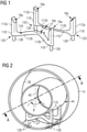
- Fig. 1 shows an example embodiment of a support structure for use in the present invention.
- the support structure is provided as a combination of two separate parts, referred to herein as support elements 110.
- the cradle interface of each support element 110 is provided in three separate partial cradle surfaces 16a, 16b. In other embodiments (not shown), the cradle interface may be divided into two, or more than three, separate partial cradle surfaces.
- each support element 110 comprising three partial cradle surfaces 16a, 16b joined by corresponding supporting struts 112a, 112b.
- each outer partial cradle surface 16a is supported by a single supporting strut 112a, while the inner partial cradle surface 16b is supported by two supporting struts 112b.
- Each support element 110 may be described as a "W-frame" support structure due to its overall configuration, although other configurations of supporting struts 112a, 112b may be employed, within the scope of the present invention.
- W-frame supports 110 ensures that only one surface is moulded, to simplify the manufacturing method and enable a low-cost manufacturing method.
- W-frame supports 110 may be manufactured by other commercially available composite manufacturing processes, such as resin infusion, machining from a block or additive manufacturing. Selection of an appropriate manufacturing method will partially depend on manufacturing volumes.
- a mould may have a surface corresponding to the partial cradle surfaces 16a, 16b, surfaces 120 of foot regions 118 and a surface 124 joining those surfaces together.
- Resin-impregnated fibre such as glass fibre cloth or carbon fibre cloth, is laid over the mould surface to a suitable thickness and the resin caused or allowed to cure. Once cured, the resulting support structure is removed from the mould surface. In this way, the surfaces which need to be accurately formed, that is, the partial cradle surfaces 16a, 16b and the surfaces 120 of the foot regions 118, are accurately formed without an unnecessarily complicated moulding process.
- each W-frame support structure 110 may be tailored to suit their functions, and to provide desired mechanical characteristics to the support structure for supporting a superconducting magnet structure within a vacuum vessel.
- each W-frame support structure 110 is formed as a single moulding, which may be in GRP or CFRP or a suitable combination, or other suitable materials which may be composite materials.
- a thermal radiation shield 26 is interposed between the superconducting magnet assembly 12 and a vacuum vessel 14.
- Features may be provided on each W-frame support structure 110 to support the thermal radiation shield. Such features may preferably provide thermal conduction between the thermal radiation shield and the support structure, so as to provide a thermal intercept as outlined above.
- the separation of the cradle interface into partial cradle surfaces 16a, 16b enables support over a wider circumferential arc of radially outer surface 44 ( Fig. 2 ) of the superconducting magnet assembly 12 while minimising any stresses due to different thermal expansion and contraction of the superconducting magnet assembly 12 and the W-frame support(s) 110.
- circumferential extremities of partial cradle surfaces 16a subtend an angle ⁇ at the cylindrical axis A-A of the cylindrical superconducting magnet assembly 12. This angle preferably lies in the range 90° - 150° but may be between 60 and 180°.
- two W-frame supports 110 are preferably provided, positioned with reflective symmetry about a plane perpendicular to the axis A, at the axial midpoint of the superconducting magnet structure.
- the W-frame support structures 110 may be positioned differently, but the arrangement shown is mechanically stable.
- Fig. 2 also shows thermal radiation shield 26 which is interposed between the superconducting magnet assembly 12 and the vacuum vessel 14.
- support elements 126 are provided between the thermal radiation shield 26 and the vacuum vessel 14.
- These support elements 126 may be in the form of GRP tubes, while the W-frame support structures 110 may be of CFRP.
- the vacuum vessel 14 will itself be supported on a vacuum vessel support 50 for example as shown in Fig. 6, and support elements 126 will bear upon the inner surface of cryogen vessel 14 at hard points 200, defined by contact with vacuum vessel support 50.
- the vacuum vessel support 50 may take different forms. In a preferred embodiment, the vacuum vessel support 50 is integrated with the OVC.
- support elements 126 have been described as GRP tubes, they may be replaced by structures of other shapes and materials, provided that such structures meet relevant requirements for mechanical strength and thermal conductivity.
- Partial cradle surfaces 16a, 16b are preferably joined to the radially outer surface 44 of the superconducting magnet assembly 12 by bonding, bolting or other suitable methods, but could simply be joined at a friction interface.
- Figs. 3-4 respectively show schematic radial and axial elevations of an assembly comprising a superconducting magnet assembly 12 supported by a support structure, according to an example embodiment of the present invention, and show further detail of W-frame supports 110 and support elements 126.
- Fig. 3 only a lower part, below cylindrical axis A-A is shown, for clarity of representation.
- superconducting magnet assembly 12 comprises coils mechanically restrained in required relative positions by other components, such as a former.
- Shield coils 21 are also shown. Shield coils are a conventional component of superconducting magnets, and comprise coils of a greater radius than the superconducting magnet assembly 12.
- a bracket 130 is the shield support bracket, providing mechanical support to the thermal radiation shield 26. Bracket 130 may also function as a thermal intercept, being thermally conductive and being thermally linked to both the support structure and the thermal radiation shield so as to carry heat from the support structure to the thermal radiation shield and so on to an associated cryogen refrigerator.
- the bracket is shown joined to the support structure between the support element 126, which may be a GRP tube, and W-frame support 110. Bracket 130 may be formed as a separate piece and assembled to the remainder of the thermal radiation shield as the superconducting magnet assembly is assembled into the vacuum vessel 14.
- Thermal contact between GRP and CFRP components preferentially occurs at the temperature of the thermal radiation shield, that is at about 50K, which is approximately the temperature at which the thermal conductivities of GRP and CFRP are equal. This temperature is provided by the thermal intercept function of bracket 130.
- each W-frame support 110 contacts a part of the outer surface 44 of the superconducting magnet assembly 12 which is axially displaced from a part of the outer surface 44 of the superconducting magnet assembly which is contacted by the outer partial cradle surfaces 16a of the W-frame support.
- the W-frame supports 110 are constructed such that the outer supports 112a holding the outer partial cradle surfaces 16a are relatively rigid, having high stiffness in the vertical (substantially tangential) direction but are relatively flexible in the horizontal (axial) direction.
- the supports 112b holding the circumferentially inner partial cradle surfaces 16b are relatively flexible in the vertical (radial) direction but relatively rigid in the horizontal (axial) direction.
- the outer supports 112a are also relatively flexible in a radial direction, to take up any differences in thermal expansion between the W-frame supports 110 and the superconducting magnet assembly 12.
- x is at least 2, and preferably in the range 5-20, and more preferably 8-15.
- Horizontal loading which may be encountered during transport or during earthquakes, for example, is largely taken by the inner cradle surface 16b, which is supported by inner supports 112b which are relatively rigid in the horizontal directions.
- the interface surface between inner cradle surface 16b and the outer surface 44 of the superconducting magnet structure is parallel to the horizontal force: the restrained axial force is a shear force at this interface.
- the supports 112a supporting the outer partial cradle surfaces 16a are relatively flexible in the horizontal directions. They make little contribution to restraining an axial or radial horizontal force, and a force appearing at the interface surface between outer cradle surfaces 16a and the outer surface 44 of the superconducting magnet assembly is a rotary shear force at this interface.
- the W-frame support By adjusting the shape and structure of the W-frame support, and the quantity and lay-up of the material in certain regions it may be arranged that a majority of vertical loading is taken, substantially tangentially, by the outer cradle surfaces 16a, while a majority of the horizontal loading is taken by the inner cradle surface 16b, with little vertical loading taken by the inner cradle surface 16b.
- the exact ratios of thicknesses, flexibility required and so on will vary depending on the exact design and materials used, and the required characteristics will vary according to the size and mass of the superconducting magnet assembly 12 used. All such characteristics may, however, be derived from a computer simulation as will be evident to those skilled in the art.
- the W-frame support 110 should preferably be constructed of only a minimum thickness of material to provide an appropriate mechanical strength, so as to keep to a minimum the thermal conduction path each W-frame support provides from the ambient temperature of the vacuum vessel to the cryogenic operational temperature of the superconducting magnet assembly. Minimising the thickness of the material of the W-frame support 110 will mean that the support will flex a certain amount during transport of the superconducting magnet assembly.
- the support element 126 is preferably mechanically attached to the W-frame support 110. This may be by bonding, bolting or other suitable methods.
- the W-frame support may be manufactured as two separate pieces, or more than two pieces, which may be assembled together into a W-frame support, or to perform the function of the W-frame as described above.
- each described W-frame could effectively be split into two "V-frames", each comprising a single outer partial cradle surface 16a, a corresponding single supporting strut 112a, a single inner partial cradle surface 16b and a corresponding single supporting strut 112b.
- each "V-frame" support may contact the vacuum vessel at a single outer partial cradle surface 16a at an outer location and a single inner partial cradle surface 16b contacting the superconducting magnet assembly at an inner location.
- Each would be bonded or bolted or otherwise attached to the superconducting magnet assembly and to the vacuum vessel.
- the two W-frame supports 110 shown in the described embodiments may be combined into a single "double-W-frame" support, manufactured in a single step, which preferably includes the single-surface moulding operation discussed above.
- the present invention accordingly provides an assembly containing a flexible support structure to support a relatively flexible superconducting magnet assembly, wherein the support structure is arranged such that, when assembled, the superconducting magnet assembly and the support structure provide a rigid whole.
- This problem arises in modern designs of superconducting magnet assembly which do not employ an encasing cryogen vessel.
- the superconducting magnet structure must be appropriately supported without causing flexure.
Landscapes
- Physics & Mathematics (AREA)
- Condensed Matter Physics & Semiconductors (AREA)
- General Physics & Mathematics (AREA)
- Engineering & Computer Science (AREA)
- Power Engineering (AREA)
- Electromagnetism (AREA)
- Containers, Films, And Cooling For Superconductive Devices (AREA)
Claims (12)
- Anordnung, umfassend eine zylindrische supraleitende Magnetanordnung (12), die von einer Trägerstruktur getragen wird, selbst umfassend mindestens ein Trägerelement (110), wobei die Trägerstruktur wiegenförmig ist,wobei jedes Trägerelement (110) zwei äußere Teilwiegenoberflächen (16a) und eine innere Teilwiegenoberfläche (16b) umfasst, die durch entsprechende Trägerstreben (112a, 112b) verbunden sind, wobei Umfangextremitäten der äußeren Teilwiegenoberflächen (16a) einem Winkel β an der Achse der zylindrischen supraleitenden Magnetanordnung (12) gegenüber liegen, wobei der Winkel β im Bereich von 60° bis 180° liegt,wobei innere Trägerstreben (112b), welche die inneren Teilwiegenoberflächen (16b) halten, in einer vertikalen radialen Richtung relativ flexibel sind, jedoch in einer horizontalen axialen Richtung relativ steif sind, wobei äußere Trägerstreben (112a), welche die äußeren Teilwiegenoberflächen (16a) halten, in einer vertikalen, im Wesentlichen tangentialen Richtung relativ steif sind, jedoch in der horizontalen axialen Richtung relativ flexibel sind, wobei in Reaktion auf eine gegebene Kraft, die auf eine Trägerstrebe (112a, 112b) in eine Richtung ausgeübt wird, in der sie relativ flexibel ist, dann eine resultierende Verschiebung um einen Faktor x größer als eine Verschiebung ist, die aus der Ausübung der gleichen gegebenen Kraft auf den gleichen Träger in eine Richtung resultiert, in der er relativ steif ist, und wobei x mindestens 2 ist,so dass vertikale und horizontale Lasten größtenteils durch jeweilige Teilwiegenoberflächen (16a, 16b) als Scherkräfte aufgenommen werden, die im Wesentlichen parallel zu der Richtung der jeweiligen Last sind, so dass vertikale Lasten in einer Richtung aufgenommen werden, die im Wesentlichen tangential zu einer zylindrischen Oberfläche (44) der zylindrischen supraleitenden Magnetanordnung (12) ist, wodurch vertikale statische Last im Wesentlichen durch die äußeren Teilwiegenoberflächen (16a) aufgenommen wird, wobei die Anordnung des Weiteren ein Vakuumgefäß (14) umfasst, in dem die supraleitende Magnetanordnung und die Trägerstruktur umschlossen sind.
- Anordnung nach Anspruch 1, wobei die Trägerstruktur mehrere tragende Elemente (110) umfasst.
- Anordnung nach Anspruch 2, wobei jedes tragende Element (110) insgesamt wiegenförmig ist.
- Anordnung nach Anspruch 1, wobei jede äußere Teilwiegenoberfläche (16a) durch eine einzelne tragende Strebe (112a) getragen wird, während die innere Teilwiegenoberfläche (16b) durch zwei tragende Streben (112b) getragen wird.
- Anordnung nach einem der vorhergehenden Ansprüche, wobei der Winkel β im Bereich von 90° bis 150° liegt.
- Anordnung nach einem der vorhergehenden Ansprüche, wobei die innere Teilwiegenoberfläche (16b) von jedem Trägerelement (110) in Kontakt mit einem Teil der radial äußeren Oberfläche (44) der zylindrischen supraleitenden Magnetanordnung (12) ist, der axial von einem Teil der radial äußeren Oberfläche (44) der zylindrischen supraleitenden Magnetanordnung (12) verschoben ist, die in Kontakt mit den äußeren Teilwiegenoberflächen (16a) steht.
- Anordnung nach Anspruch 1, wobei x im Bereich von 5 bis 20 liegt.
- Anordnung nach Anspruch 7, wobei x im Bereich von 8 bis 15 liegt.
- Anordnung nach einem der vorhergehenden Ansprüche, wobei jedes tragende Element (110) eine einzelne geformte Oberfläche einschließt, wobei andere Oberflächen des Elements nicht geformt sind.
- Anordnung nach einem der vorhergehenden Ansprüche, wobei jedes tragende Element (110) eine Halterung (130) trägt, die einen mechanischen Träger für eine Wärmestrahlungsabschirmung (26) bereitstellt.
- Anordnung nach Anspruch 10, wobei jede Halterung (130) thermisch mit einem entsprechenden tragenden Element (110) und der Wärmestrahlungsabschirmung (26) verknüpft ist, so dass jede Halterung einen Wärmeabfänger für das tragende Element bereitstellt.
- Anordnung nach einem der vorhergehenden Ansprüche, wobei ein Teil der Trägerstruktur ein glasverstärkter Kunststoff (GRP) ist, während ein anderer Teil kohlefaserverstärkter Kunststoff (CFRP) ist.
Applications Claiming Priority (2)
| Application Number | Priority Date | Filing Date | Title |
|---|---|---|---|
| GB1720576.6A GB2569184B (en) | 2017-12-11 | 2017-12-11 | An assembly comprising a cylindrical structure supported by a support structure |
| PCT/EP2018/082101 WO2019115189A1 (en) | 2017-12-11 | 2018-11-21 | An assembly comprising a cylindrical structure supported by a support structure |
Publications (3)
| Publication Number | Publication Date |
|---|---|
| EP3724672A1 EP3724672A1 (de) | 2020-10-21 |
| EP3724672B1 true EP3724672B1 (de) | 2022-03-16 |
| EP3724672B8 EP3724672B8 (de) | 2022-04-20 |
Family
ID=61007172
Family Applications (1)
| Application Number | Title | Priority Date | Filing Date |
|---|---|---|---|
| EP18815528.7A Active EP3724672B8 (de) | 2017-12-11 | 2018-11-21 | Anordnung mit einer zylindrischen struktur, die von einer trägerstruktur getragen wird |
Country Status (7)
| Country | Link |
|---|---|
| US (1) | US11387026B2 (de) |
| EP (1) | EP3724672B8 (de) |
| JP (1) | JP7216096B2 (de) |
| KR (1) | KR102539593B1 (de) |
| CN (3) | CN111465869B (de) |
| GB (1) | GB2569184B (de) |
| WO (1) | WO2019115189A1 (de) |
Families Citing this family (4)
| Publication number | Priority date | Publication date | Assignee | Title |
|---|---|---|---|---|
| GB2569184B (en) * | 2017-12-11 | 2020-02-26 | Siemens Healthcare Ltd | An assembly comprising a cylindrical structure supported by a support structure |
| GB2587378B (en) | 2019-09-26 | 2021-10-13 | Siemens Healthcare Ltd | Coil support |
| CN112886511B (zh) * | 2021-01-05 | 2022-10-18 | 国网内蒙古东部电力有限公司 | 一种管廊式跳线支撑结构、输电系统及方法 |
| CN115831527B (zh) * | 2022-11-21 | 2023-09-12 | 苏州八匹马超导科技有限公司 | 一种超导磁体骨架顶杆机构 |
Family Cites Families (33)
| Publication number | Priority date | Publication date | Assignee | Title |
|---|---|---|---|---|
| US2025789A (en) * | 1931-08-05 | 1935-12-31 | Aluminum Co Of America | Support |
| US3133144A (en) * | 1962-08-16 | 1964-05-12 | Bell Telephone Labor Inc | Cryostat |
| US4595899A (en) * | 1984-07-06 | 1986-06-17 | The Board Of Trustees Of The Leland Stanford Junior University | Magnetic structure for NMR applications and the like |
| US4660013A (en) | 1985-09-23 | 1987-04-21 | General Electric Company | Compact whole body resistive magnetic resonance imaging magnet |
| JPS63118208A (ja) * | 1986-11-07 | 1988-05-23 | 中外商工株式会社 | セメント材混和方法 |
| JP2563283B2 (ja) * | 1986-11-21 | 1996-12-11 | 株式会社東芝 | 磁気共鳴診断装置 |
| JPS63118208U (de) * | 1987-01-23 | 1988-07-30 | ||
| JP2617937B2 (ja) * | 1987-05-26 | 1997-06-11 | 三菱電機株式会社 | 電磁石装置 |
| US4822772A (en) * | 1987-08-14 | 1989-04-18 | Houston Area Research Center | Electromagnet and method of forming same |
| US5446433A (en) * | 1994-09-21 | 1995-08-29 | General Electric Company | Superconducting magnet having a shock-resistant support structure |
| JP2002141218A (ja) * | 2000-11-01 | 2002-05-17 | Sumitomo Heavy Ind Ltd | 酸化物超電導コイル巻枠 |
| JP3851215B2 (ja) * | 2002-04-30 | 2006-11-29 | ジャパンスーパーコンダクタテクノロジー株式会社 | 超電導マグネット装置 |
| AU2003242938A1 (en) | 2002-07-04 | 2004-01-23 | Koninklijke Philips Electronics N.V. | An mri system with a conductive member having a damping effect for vibrations |
| GB2420019B (en) * | 2002-12-10 | 2006-11-15 | Ge Med Sys Global Tech Co Llc | Support member for a superconducting magnet assembly |
| EP1815263A1 (de) * | 2004-11-17 | 2007-08-08 | Koninklijke Philips Electronics N.V. | Magnetresonanzsystem mit reduzierter lautstärke |
| GB2440350B (en) * | 2006-07-25 | 2009-10-14 | Siemens Magnet Technology Ltd | A cryostat comprising a cryogen vessel suspended within an outer vacuum container |
| US7560929B2 (en) * | 2006-08-14 | 2009-07-14 | Fonar Corporation | Ferromagnetic frame magnet with superconducting coils |
| GB2441795B (en) | 2006-09-15 | 2010-06-02 | Siemens Magnet Technology Ltd | A supported superconducting magnet |
| US7646272B1 (en) * | 2007-10-12 | 2010-01-12 | The United States Of America As Represented By The United States Department Of Energy | Freely oriented portable superconducting magnet |
| US8314615B2 (en) * | 2009-12-22 | 2012-11-20 | General Electric Company | Apparatus and method to improve magnet stability in an MRI system |
| EP3572823B1 (de) * | 2010-02-24 | 2022-04-06 | ViewRay Technologies, Inc. | Aufgeteiltes system zur bildgebung magnetischer resonanzen |
| GB2480637B (en) * | 2010-05-26 | 2013-02-20 | Siemens Plc | Solenoidal magnets having supported outer coils |
| JP2012054260A (ja) | 2010-08-31 | 2012-03-15 | Hitachi Ltd | 超電導マグネット装置 |
| GB2490189B (en) * | 2011-04-20 | 2014-04-23 | Siemens Plc | Superconducting magnets with thermal radiation shields |
| JP6276033B2 (ja) * | 2013-01-15 | 2018-02-07 | 株式会社神戸製鋼所 | 極低温装置及び被冷却体に対する冷凍機の接続及び切り離し方法 |
| GB2521470B (en) * | 2013-12-20 | 2015-11-11 | Siemens Plc | Support structure for cylindrical superconducting coil structure |
| DE102014001526B4 (de) * | 2014-02-07 | 2022-02-24 | Festo Se & Co. Kg | Supraleiter-Lagermittel und Vorrichtung zur Materialuntersuchung und/oder Materialbearbeitung |
| JP6483729B2 (ja) * | 2014-05-21 | 2019-03-13 | コーニンクレッカ フィリップス エヌ ヴェKoninklijke Philips N.V. | 超電導コイルを支持する装置及び方法並びに超電導コイル装置を有する装置 |
| GB2532314B (en) * | 2014-10-27 | 2018-05-02 | Siemens Healthcare Ltd | Support of superconducting coils for MRI systems |
| DE102015201373A1 (de) * | 2015-01-27 | 2016-07-28 | Siemens Aktiengesellschaft | Supraleitende Magnetanordnung, insbesondere für einen Magnetresonanztomographen |
| CN205654973U (zh) * | 2016-04-25 | 2016-10-19 | 中山市威德轻工机电制品有限公司 | 一种w型管体支撑架 |
| GB2561164B (en) * | 2017-03-30 | 2020-04-29 | Siemens Healthcare Ltd | Connection of coils to support structures in superconducting magnets |
| GB2569184B (en) * | 2017-12-11 | 2020-02-26 | Siemens Healthcare Ltd | An assembly comprising a cylindrical structure supported by a support structure |
-
2017
- 2017-12-11 GB GB1720576.6A patent/GB2569184B/en not_active Expired - Fee Related
-
2018
- 2018-11-21 US US16/771,560 patent/US11387026B2/en active Active
- 2018-11-21 KR KR1020207016187A patent/KR102539593B1/ko active Active
- 2018-11-21 WO PCT/EP2018/082101 patent/WO2019115189A1/en not_active Ceased
- 2018-11-21 JP JP2020531731A patent/JP7216096B2/ja active Active
- 2018-11-21 EP EP18815528.7A patent/EP3724672B8/de active Active
- 2018-11-21 CN CN201880079870.9A patent/CN111465869B/zh active Active
- 2018-12-06 CN CN201822043321.6U patent/CN209747269U/zh not_active Withdrawn - After Issue
- 2018-12-06 CN CN201811489258.7A patent/CN109979702B/zh active Active
Also Published As
| Publication number | Publication date |
|---|---|
| KR102539593B1 (ko) | 2023-06-01 |
| KR20200097256A (ko) | 2020-08-18 |
| WO2019115189A1 (en) | 2019-06-20 |
| CN209747269U (zh) | 2019-12-06 |
| GB2569184A (en) | 2019-06-12 |
| EP3724672B8 (de) | 2022-04-20 |
| US20210183551A1 (en) | 2021-06-17 |
| US11387026B2 (en) | 2022-07-12 |
| CN109979702B (zh) | 2022-10-21 |
| CN111465869B (zh) | 2023-05-23 |
| CN111465869A (zh) | 2020-07-28 |
| JP7216096B2 (ja) | 2023-01-31 |
| JP2021506134A (ja) | 2021-02-18 |
| GB2569184B (en) | 2020-02-26 |
| EP3724672A1 (de) | 2020-10-21 |
| CN109979702A (zh) | 2019-07-05 |
| GB201720576D0 (en) | 2018-01-24 |
Similar Documents
| Publication | Publication Date | Title |
|---|---|---|
| US11387026B2 (en) | Assembly comprising a cylindrical structure supported by a support structure | |
| US8228147B2 (en) | Supported superconducting magnet | |
| US6011454A (en) | Superconducting magnet suspension assembly | |
| US9285073B2 (en) | Non-rotating flexure bearings for cryocoolers and other devices | |
| CN107076815B (zh) | 用于mri系统的超导线圈的支撑 | |
| CN108695037B (zh) | 用于在超导磁体中支撑结构的线圈连接 | |
| EP0450972B1 (de) | Supraleitender Magnet | |
| JP2018534759A (ja) | Hts磁石のための支持構造体 | |
| CN114450760B (zh) | 超导磁体组件 | |
| EP0450971B1 (de) | Supraleitender Magnet | |
| CN106030328A (zh) | 用于筒状超导线圈结构的支撑结构 | |
| US20120309630A1 (en) | Penetration tube assemblies for reducing cryostat heat load | |
| EP1003181B1 (de) | Schalenanordnung aus Verbundlaminat für Anwendung in Magneten | |
| CN118039286A (zh) | 支撑座、超导磁体组件及支撑座的制造方法 | |
| CN108253280A (zh) | 一种集成有安装接口的复合材料球形气瓶及其制作方法 | |
| EP3220816B1 (de) | System und verfahren zur verbesserung der wärmereflektivität einer kryogenen komponente | |
| JP3647266B2 (ja) | 超電導マグネット装置 | |
| GB2579158A (en) | Connection of coils to support structures in superconducting magnets |
Legal Events
| Date | Code | Title | Description |
|---|---|---|---|
| STAA | Information on the status of an ep patent application or granted ep patent |
Free format text: STATUS: UNKNOWN |
|
| STAA | Information on the status of an ep patent application or granted ep patent |
Free format text: STATUS: THE INTERNATIONAL PUBLICATION HAS BEEN MADE |
|
| PUAI | Public reference made under article 153(3) epc to a published international application that has entered the european phase |
Free format text: ORIGINAL CODE: 0009012 |
|
| STAA | Information on the status of an ep patent application or granted ep patent |
Free format text: STATUS: REQUEST FOR EXAMINATION WAS MADE |
|
| 17P | Request for examination filed |
Effective date: 20200408 |
|
| AK | Designated contracting states |
Kind code of ref document: A1 Designated state(s): AL AT BE BG CH CY CZ DE DK EE ES FI FR GB GR HR HU IE IS IT LI LT LU LV MC MK MT NL NO PL PT RO RS SE SI SK SM TR |
|
| AX | Request for extension of the european patent |
Extension state: BA ME |
|
| DAV | Request for validation of the european patent (deleted) | ||
| DAX | Request for extension of the european patent (deleted) | ||
| GRAP | Despatch of communication of intention to grant a patent |
Free format text: ORIGINAL CODE: EPIDOSNIGR1 |
|
| STAA | Information on the status of an ep patent application or granted ep patent |
Free format text: STATUS: GRANT OF PATENT IS INTENDED |
|
| INTG | Intention to grant announced |
Effective date: 20210607 |
|
| GRAJ | Information related to disapproval of communication of intention to grant by the applicant or resumption of examination proceedings by the epo deleted |
Free format text: ORIGINAL CODE: EPIDOSDIGR1 |
|
| STAA | Information on the status of an ep patent application or granted ep patent |
Free format text: STATUS: REQUEST FOR EXAMINATION WAS MADE |
|
| INTC | Intention to grant announced (deleted) | ||
| GRAP | Despatch of communication of intention to grant a patent |
Free format text: ORIGINAL CODE: EPIDOSNIGR1 |
|
| STAA | Information on the status of an ep patent application or granted ep patent |
Free format text: STATUS: GRANT OF PATENT IS INTENDED |
|
| INTG | Intention to grant announced |
Effective date: 20211007 |
|
| GRAS | Grant fee paid |
Free format text: ORIGINAL CODE: EPIDOSNIGR3 |
|
| GRAA | (expected) grant |
Free format text: ORIGINAL CODE: 0009210 |
|
| STAA | Information on the status of an ep patent application or granted ep patent |
Free format text: STATUS: THE PATENT HAS BEEN GRANTED |
|
| REG | Reference to a national code |
Ref country code: DE Ref legal event code: R081 Ref document number: 602018032428 Country of ref document: DE Owner name: SIEMENS HEALTHCARE LTD., CAMBERLEY, GB Free format text: FORMER OWNER: SIEMENS HEALTHCARE LTD., FRIMLEY, CAMBERLEY, GB |
|
| AK | Designated contracting states |
Kind code of ref document: B1 Designated state(s): AL AT BE BG CH CY CZ DE DK EE ES FI FR GB GR HR HU IE IS IT LI LT LU LV MC MK MT NL NO PL PT RO RS SE SI SK SM TR |
|
| REG | Reference to a national code |
Ref country code: GB Ref legal event code: FG4D |
|
| RAP4 | Party data changed (patent owner data changed or rights of a patent transferred) |
Owner name: SIEMENS HEALTHCARE LIMITED |
|
| REG | Reference to a national code |
Ref country code: CH Ref legal event code: PK Free format text: BERICHTIGUNG B8 Ref country code: CH Ref legal event code: EP |
|
| REG | Reference to a national code |
Ref country code: DE Ref legal event code: R096 Ref document number: 602018032428 Country of ref document: DE |
|
| REG | Reference to a national code |
Ref country code: IE Ref legal event code: FG4D |
|
| REG | Reference to a national code |
Ref country code: AT Ref legal event code: REF Ref document number: 1476276 Country of ref document: AT Kind code of ref document: T Effective date: 20220415 |
|
| REG | Reference to a national code |
Ref country code: LT Ref legal event code: MG9D |
|
| REG | Reference to a national code |
Ref country code: NL Ref legal event code: MP Effective date: 20220316 |
|
| PG25 | Lapsed in a contracting state [announced via postgrant information from national office to epo] |
Ref country code: SE Free format text: LAPSE BECAUSE OF FAILURE TO SUBMIT A TRANSLATION OF THE DESCRIPTION OR TO PAY THE FEE WITHIN THE PRESCRIBED TIME-LIMIT Effective date: 20220316 Ref country code: RS Free format text: LAPSE BECAUSE OF FAILURE TO SUBMIT A TRANSLATION OF THE DESCRIPTION OR TO PAY THE FEE WITHIN THE PRESCRIBED TIME-LIMIT Effective date: 20220316 Ref country code: NO Free format text: LAPSE BECAUSE OF FAILURE TO SUBMIT A TRANSLATION OF THE DESCRIPTION OR TO PAY THE FEE WITHIN THE PRESCRIBED TIME-LIMIT Effective date: 20220616 Ref country code: LT Free format text: LAPSE BECAUSE OF FAILURE TO SUBMIT A TRANSLATION OF THE DESCRIPTION OR TO PAY THE FEE WITHIN THE PRESCRIBED TIME-LIMIT Effective date: 20220316 Ref country code: HR Free format text: LAPSE BECAUSE OF FAILURE TO SUBMIT A TRANSLATION OF THE DESCRIPTION OR TO PAY THE FEE WITHIN THE PRESCRIBED TIME-LIMIT Effective date: 20220316 Ref country code: BG Free format text: LAPSE BECAUSE OF FAILURE TO SUBMIT A TRANSLATION OF THE DESCRIPTION OR TO PAY THE FEE WITHIN THE PRESCRIBED TIME-LIMIT Effective date: 20220616 |
|
| REG | Reference to a national code |
Ref country code: AT Ref legal event code: MK05 Ref document number: 1476276 Country of ref document: AT Kind code of ref document: T Effective date: 20220316 |
|
| PG25 | Lapsed in a contracting state [announced via postgrant information from national office to epo] |
Ref country code: LV Free format text: LAPSE BECAUSE OF FAILURE TO SUBMIT A TRANSLATION OF THE DESCRIPTION OR TO PAY THE FEE WITHIN THE PRESCRIBED TIME-LIMIT Effective date: 20220316 Ref country code: GR Free format text: LAPSE BECAUSE OF FAILURE TO SUBMIT A TRANSLATION OF THE DESCRIPTION OR TO PAY THE FEE WITHIN THE PRESCRIBED TIME-LIMIT Effective date: 20220617 Ref country code: FI Free format text: LAPSE BECAUSE OF FAILURE TO SUBMIT A TRANSLATION OF THE DESCRIPTION OR TO PAY THE FEE WITHIN THE PRESCRIBED TIME-LIMIT Effective date: 20220316 |
|
| PG25 | Lapsed in a contracting state [announced via postgrant information from national office to epo] |
Ref country code: NL Free format text: LAPSE BECAUSE OF FAILURE TO SUBMIT A TRANSLATION OF THE DESCRIPTION OR TO PAY THE FEE WITHIN THE PRESCRIBED TIME-LIMIT Effective date: 20220316 |
|
| PG25 | Lapsed in a contracting state [announced via postgrant information from national office to epo] |
Ref country code: SM Free format text: LAPSE BECAUSE OF FAILURE TO SUBMIT A TRANSLATION OF THE DESCRIPTION OR TO PAY THE FEE WITHIN THE PRESCRIBED TIME-LIMIT Effective date: 20220316 Ref country code: SK Free format text: LAPSE BECAUSE OF FAILURE TO SUBMIT A TRANSLATION OF THE DESCRIPTION OR TO PAY THE FEE WITHIN THE PRESCRIBED TIME-LIMIT Effective date: 20220316 Ref country code: RO Free format text: LAPSE BECAUSE OF FAILURE TO SUBMIT A TRANSLATION OF THE DESCRIPTION OR TO PAY THE FEE WITHIN THE PRESCRIBED TIME-LIMIT Effective date: 20220316 Ref country code: PT Free format text: LAPSE BECAUSE OF FAILURE TO SUBMIT A TRANSLATION OF THE DESCRIPTION OR TO PAY THE FEE WITHIN THE PRESCRIBED TIME-LIMIT Effective date: 20220718 Ref country code: ES Free format text: LAPSE BECAUSE OF FAILURE TO SUBMIT A TRANSLATION OF THE DESCRIPTION OR TO PAY THE FEE WITHIN THE PRESCRIBED TIME-LIMIT Effective date: 20220316 Ref country code: EE Free format text: LAPSE BECAUSE OF FAILURE TO SUBMIT A TRANSLATION OF THE DESCRIPTION OR TO PAY THE FEE WITHIN THE PRESCRIBED TIME-LIMIT Effective date: 20220316 Ref country code: CZ Free format text: LAPSE BECAUSE OF FAILURE TO SUBMIT A TRANSLATION OF THE DESCRIPTION OR TO PAY THE FEE WITHIN THE PRESCRIBED TIME-LIMIT Effective date: 20220316 Ref country code: AT Free format text: LAPSE BECAUSE OF FAILURE TO SUBMIT A TRANSLATION OF THE DESCRIPTION OR TO PAY THE FEE WITHIN THE PRESCRIBED TIME-LIMIT Effective date: 20220316 |
|
| PG25 | Lapsed in a contracting state [announced via postgrant information from national office to epo] |
Ref country code: PL Free format text: LAPSE BECAUSE OF FAILURE TO SUBMIT A TRANSLATION OF THE DESCRIPTION OR TO PAY THE FEE WITHIN THE PRESCRIBED TIME-LIMIT Effective date: 20220316 Ref country code: IS Free format text: LAPSE BECAUSE OF FAILURE TO SUBMIT A TRANSLATION OF THE DESCRIPTION OR TO PAY THE FEE WITHIN THE PRESCRIBED TIME-LIMIT Effective date: 20220716 Ref country code: AL Free format text: LAPSE BECAUSE OF FAILURE TO SUBMIT A TRANSLATION OF THE DESCRIPTION OR TO PAY THE FEE WITHIN THE PRESCRIBED TIME-LIMIT Effective date: 20220316 |
|
| REG | Reference to a national code |
Ref country code: DE Ref legal event code: R097 Ref document number: 602018032428 Country of ref document: DE |
|
| PLBE | No opposition filed within time limit |
Free format text: ORIGINAL CODE: 0009261 |
|
| STAA | Information on the status of an ep patent application or granted ep patent |
Free format text: STATUS: NO OPPOSITION FILED WITHIN TIME LIMIT |
|
| PG25 | Lapsed in a contracting state [announced via postgrant information from national office to epo] |
Ref country code: DK Free format text: LAPSE BECAUSE OF FAILURE TO SUBMIT A TRANSLATION OF THE DESCRIPTION OR TO PAY THE FEE WITHIN THE PRESCRIBED TIME-LIMIT Effective date: 20220316 |
|
| 26N | No opposition filed |
Effective date: 20221219 |
|
| PG25 | Lapsed in a contracting state [announced via postgrant information from national office to epo] |
Ref country code: SI Free format text: LAPSE BECAUSE OF FAILURE TO SUBMIT A TRANSLATION OF THE DESCRIPTION OR TO PAY THE FEE WITHIN THE PRESCRIBED TIME-LIMIT Effective date: 20220316 |
|
| PG25 | Lapsed in a contracting state [announced via postgrant information from national office to epo] |
Ref country code: MC Free format text: LAPSE BECAUSE OF FAILURE TO SUBMIT A TRANSLATION OF THE DESCRIPTION OR TO PAY THE FEE WITHIN THE PRESCRIBED TIME-LIMIT Effective date: 20220316 |
|
| REG | Reference to a national code |
Ref country code: CH Ref legal event code: PL |
|
| REG | Reference to a national code |
Ref country code: BE Ref legal event code: MM Effective date: 20221130 |
|
| PG25 | Lapsed in a contracting state [announced via postgrant information from national office to epo] |
Ref country code: LI Free format text: LAPSE BECAUSE OF NON-PAYMENT OF DUE FEES Effective date: 20221130 Ref country code: CH Free format text: LAPSE BECAUSE OF NON-PAYMENT OF DUE FEES Effective date: 20221130 |
|
| PG25 | Lapsed in a contracting state [announced via postgrant information from national office to epo] |
Ref country code: LU Free format text: LAPSE BECAUSE OF NON-PAYMENT OF DUE FEES Effective date: 20221121 |
|
| PG25 | Lapsed in a contracting state [announced via postgrant information from national office to epo] |
Ref country code: IE Free format text: LAPSE BECAUSE OF NON-PAYMENT OF DUE FEES Effective date: 20221121 |
|
| PG25 | Lapsed in a contracting state [announced via postgrant information from national office to epo] |
Ref country code: FR Free format text: LAPSE BECAUSE OF NON-PAYMENT OF DUE FEES Effective date: 20221130 Ref country code: BE Free format text: LAPSE BECAUSE OF NON-PAYMENT OF DUE FEES Effective date: 20221130 |
|
| PG25 | Lapsed in a contracting state [announced via postgrant information from national office to epo] |
Ref country code: CY Free format text: LAPSE BECAUSE OF FAILURE TO SUBMIT A TRANSLATION OF THE DESCRIPTION OR TO PAY THE FEE WITHIN THE PRESCRIBED TIME-LIMIT Effective date: 20220316 |
|
| PG25 | Lapsed in a contracting state [announced via postgrant information from national office to epo] |
Ref country code: MK Free format text: LAPSE BECAUSE OF FAILURE TO SUBMIT A TRANSLATION OF THE DESCRIPTION OR TO PAY THE FEE WITHIN THE PRESCRIBED TIME-LIMIT Effective date: 20220316 Ref country code: HU Free format text: LAPSE BECAUSE OF FAILURE TO SUBMIT A TRANSLATION OF THE DESCRIPTION OR TO PAY THE FEE WITHIN THE PRESCRIBED TIME-LIMIT; INVALID AB INITIO Effective date: 20181121 |
|
| PG25 | Lapsed in a contracting state [announced via postgrant information from national office to epo] |
Ref country code: MT Free format text: LAPSE BECAUSE OF FAILURE TO SUBMIT A TRANSLATION OF THE DESCRIPTION OR TO PAY THE FEE WITHIN THE PRESCRIBED TIME-LIMIT Effective date: 20220316 |
|
| REG | Reference to a national code |
Ref country code: DE Ref legal event code: R082 Ref document number: 602018032428 Country of ref document: DE |
|
| PG25 | Lapsed in a contracting state [announced via postgrant information from national office to epo] |
Ref country code: TR Free format text: LAPSE BECAUSE OF FAILURE TO SUBMIT A TRANSLATION OF THE DESCRIPTION OR TO PAY THE FEE WITHIN THE PRESCRIBED TIME-LIMIT Effective date: 20220316 |
|
| PGFP | Annual fee paid to national office [announced via postgrant information from national office to epo] |
Ref country code: GB Payment date: 20251211 Year of fee payment: 8 |
|
| PGFP | Annual fee paid to national office [announced via postgrant information from national office to epo] |
Ref country code: IT Payment date: 20251125 Year of fee payment: 8 |
|
| PGFP | Annual fee paid to national office [announced via postgrant information from national office to epo] |
Ref country code: DE Payment date: 20260119 Year of fee payment: 8 |