EP3723921B1 - Elektromagnetische extrusion und deren betriebsverfahren - Google Patents
Elektromagnetische extrusion und deren betriebsverfahren Download PDFInfo
- Publication number
- EP3723921B1 EP3723921B1 EP18889363.0A EP18889363A EP3723921B1 EP 3723921 B1 EP3723921 B1 EP 3723921B1 EP 18889363 A EP18889363 A EP 18889363A EP 3723921 B1 EP3723921 B1 EP 3723921B1
- Authority
- EP
- European Patent Office
- Prior art keywords
- extrusion
- electromagnetic
- chamber
- extrusion material
- magnetic field
- Prior art date
- Legal status (The legal status is an assumption and is not a legal conclusion. Google has not performed a legal analysis and makes no representation as to the accuracy of the status listed.)
- Active
Links
Images


Classifications
-
- B—PERFORMING OPERATIONS; TRANSPORTING
- B21—MECHANICAL METAL-WORKING WITHOUT ESSENTIALLY REMOVING MATERIAL; PUNCHING METAL
- B21C—MANUFACTURE OF METAL SHEETS, WIRE, RODS, TUBES, PROFILES OR LIKE SEMI-MANUFACTURED PRODUCTS OTHERWISE THAN BY ROLLING; AUXILIARY OPERATIONS USED IN CONNECTION WITH METAL-WORKING WITHOUT ESSENTIALLY REMOVING MATERIAL
- B21C23/00—Extruding metal; Impact extrusion
- B21C23/02—Making uncoated products
- B21C23/03—Making uncoated products by both direct and backward extrusion
-
- B—PERFORMING OPERATIONS; TRANSPORTING
- B22—CASTING; POWDER METALLURGY
- B22F—WORKING METALLIC POWDER; MANUFACTURE OF ARTICLES FROM METALLIC POWDER; MAKING METALLIC POWDER; APPARATUS OR DEVICES SPECIALLY ADAPTED FOR METALLIC POWDER
- B22F3/00—Manufacture of workpieces or articles from metallic powder characterised by the manner of compacting or sintering; Apparatus specially adapted therefor ; Presses and furnaces
- B22F3/20—Manufacture of workpieces or articles from metallic powder characterised by the manner of compacting or sintering; Apparatus specially adapted therefor ; Presses and furnaces by extruding
-
- B—PERFORMING OPERATIONS; TRANSPORTING
- B21—MECHANICAL METAL-WORKING WITHOUT ESSENTIALLY REMOVING MATERIAL; PUNCHING METAL
- B21C—MANUFACTURE OF METAL SHEETS, WIRE, RODS, TUBES, PROFILES OR LIKE SEMI-MANUFACTURED PRODUCTS OTHERWISE THAN BY ROLLING; AUXILIARY OPERATIONS USED IN CONNECTION WITH METAL-WORKING WITHOUT ESSENTIALLY REMOVING MATERIAL
- B21C23/00—Extruding metal; Impact extrusion
- B21C23/02—Making uncoated products
- B21C23/04—Making uncoated products by direct extrusion
-
- B—PERFORMING OPERATIONS; TRANSPORTING
- B21—MECHANICAL METAL-WORKING WITHOUT ESSENTIALLY REMOVING MATERIAL; PUNCHING METAL
- B21C—MANUFACTURE OF METAL SHEETS, WIRE, RODS, TUBES, PROFILES OR LIKE SEMI-MANUFACTURED PRODUCTS OTHERWISE THAN BY ROLLING; AUXILIARY OPERATIONS USED IN CONNECTION WITH METAL-WORKING WITHOUT ESSENTIALLY REMOVING MATERIAL
- B21C23/00—Extruding metal; Impact extrusion
- B21C23/02—Making uncoated products
- B21C23/20—Making uncoated products by backward extrusion
-
- B—PERFORMING OPERATIONS; TRANSPORTING
- B21—MECHANICAL METAL-WORKING WITHOUT ESSENTIALLY REMOVING MATERIAL; PUNCHING METAL
- B21C—MANUFACTURE OF METAL SHEETS, WIRE, RODS, TUBES, PROFILES OR LIKE SEMI-MANUFACTURED PRODUCTS OTHERWISE THAN BY ROLLING; AUXILIARY OPERATIONS USED IN CONNECTION WITH METAL-WORKING WITHOUT ESSENTIALLY REMOVING MATERIAL
- B21C23/00—Extruding metal; Impact extrusion
- B21C23/21—Presses specially adapted for extruding metal
- B21C23/212—Details
-
- B—PERFORMING OPERATIONS; TRANSPORTING
- B21—MECHANICAL METAL-WORKING WITHOUT ESSENTIALLY REMOVING MATERIAL; PUNCHING METAL
- B21C—MANUFACTURE OF METAL SHEETS, WIRE, RODS, TUBES, PROFILES OR LIKE SEMI-MANUFACTURED PRODUCTS OTHERWISE THAN BY ROLLING; AUXILIARY OPERATIONS USED IN CONNECTION WITH METAL-WORKING WITHOUT ESSENTIALLY REMOVING MATERIAL
- B21C27/00—Containers for metal to be extruded
-
- B—PERFORMING OPERATIONS; TRANSPORTING
- B21—MECHANICAL METAL-WORKING WITHOUT ESSENTIALLY REMOVING MATERIAL; PUNCHING METAL
- B21C—MANUFACTURE OF METAL SHEETS, WIRE, RODS, TUBES, PROFILES OR LIKE SEMI-MANUFACTURED PRODUCTS OTHERWISE THAN BY ROLLING; AUXILIARY OPERATIONS USED IN CONNECTION WITH METAL-WORKING WITHOUT ESSENTIALLY REMOVING MATERIAL
- B21C29/00—Cooling or heating extruded work or parts of the extrusion press
- B21C29/02—Cooling or heating extruded work or parts of the extrusion press of containers for metal to be extruded
-
- B—PERFORMING OPERATIONS; TRANSPORTING
- B29—WORKING OF PLASTICS; WORKING OF SUBSTANCES IN A PLASTIC STATE IN GENERAL
- B29C—SHAPING OR JOINING OF PLASTICS; SHAPING OF MATERIAL IN A PLASTIC STATE, NOT OTHERWISE PROVIDED FOR; AFTER-TREATMENT OF THE SHAPED PRODUCTS, e.g. REPAIRING
- B29C48/00—Extrusion moulding, i.e. expressing the moulding material through a die or nozzle which imparts the desired form; Apparatus therefor
- B29C48/03—Extrusion moulding, i.e. expressing the moulding material through a die or nozzle which imparts the desired form; Apparatus therefor characterised by the shape of the extruded material at extrusion
- B29C48/09—Articles with cross-sections having partially or fully enclosed cavities, e.g. pipes or channels
-
- B—PERFORMING OPERATIONS; TRANSPORTING
- B29—WORKING OF PLASTICS; WORKING OF SUBSTANCES IN A PLASTIC STATE IN GENERAL
- B29C—SHAPING OR JOINING OF PLASTICS; SHAPING OF MATERIAL IN A PLASTIC STATE, NOT OTHERWISE PROVIDED FOR; AFTER-TREATMENT OF THE SHAPED PRODUCTS, e.g. REPAIRING
- B29C48/00—Extrusion moulding, i.e. expressing the moulding material through a die or nozzle which imparts the desired form; Apparatus therefor
- B29C48/14—Extrusion moulding, i.e. expressing the moulding material through a die or nozzle which imparts the desired form; Apparatus therefor characterised by the particular extruding conditions, e.g. in a modified atmosphere or by using vibration
- B29C48/142—Extrusion moulding, i.e. expressing the moulding material through a die or nozzle which imparts the desired form; Apparatus therefor characterised by the particular extruding conditions, e.g. in a modified atmosphere or by using vibration using force fields, e.g. gravity or electrical fields
-
- B—PERFORMING OPERATIONS; TRANSPORTING
- B30—PRESSES
- B30B—PRESSES IN GENERAL
- B30B11/00—Presses specially adapted for forming shaped articles from material in particulate or plastic state, e.g. briquetting presses, tabletting presses
- B30B11/008—Applying a magnetic field to the material
-
- B—PERFORMING OPERATIONS; TRANSPORTING
- B30—PRESSES
- B30B—PRESSES IN GENERAL
- B30B11/00—Presses specially adapted for forming shaped articles from material in particulate or plastic state, e.g. briquetting presses, tabletting presses
- B30B11/22—Extrusion presses; Dies therefor
- B30B11/26—Extrusion presses; Dies therefor using press rams
-
- B—PERFORMING OPERATIONS; TRANSPORTING
- B22—CASTING; POWDER METALLURGY
- B22F—WORKING METALLIC POWDER; MANUFACTURE OF ARTICLES FROM METALLIC POWDER; MAKING METALLIC POWDER; APPARATUS OR DEVICES SPECIALLY ADAPTED FOR METALLIC POWDER
- B22F2999/00—Aspects linked to processes or compositions used in powder metallurgy
Definitions
- the present disclosure relates generally to a system and method for an improved material flow through an extrusion machine by altering the material properties of an extrusion material in a magnetic field.
- Extrusion is the processes of shaping material, such as plastic, metal, alloys, or billets, by pushing the material through a shaped opening in a die. Material pushed through the die exits the die as an elongated piece of material with the same shape as the die opening.
- the extrusion process for metal, such as an aluminum billet is used to mass produce straight, semi-finished products.
- High-strength aluminum products are used, for example, in the automotive industry and must have consistent material properties (e.g., microstructural and mechanical properties) throughout its entirety. However, the material properties of the products can be affected by the extrusion process, resulting in an inferior product.
- a solid cross section or a hollow cross section of an aluminum product can be produced by indirect extrusion; however, manufacturing conditions can cause recrystallization on a long side of a billet when homogenizing treatment temperature conditions or/and a high extrusion temperature allows for intermetallic compounds of these elements to grow. Additionally, the tooling itself can be damaged from the extrusion process. Further relevant prior art is described in US 3 744 890 A , US 3 928 995 A , US 3 874 207 A , US 2002/189313 A1 , US 3 668 748 A , US 3 946 794 A , GB 2 022 001 A , US 4 304 537 A and US 4 304 537 A .
- an applied magnetic field can change the plastic behavior of crystalline materials, a phenomenon known as magnetoplasticity.
- the magnetoplasticity phenomenon has been explained by assuming that a dangling bond of a paramagnetic impurity forms a radical pair with a dangling bond of the dislocation core. It has been shown that an applied magnetic field can induce transitions between different spin states of such pairs characterized by different binding energies, and thus facilitate dislocation depinning from the impurity, which thereby enhances the crystal plasticity.
- An electromagnetic extrusion system for extruding a material.
- the electromagnetic extrusion system comprises a container defining a chamber for holding the extrusion material, and a die defining an opening in fluid communication with the chamber for the extrusion material to exit as an extrusion.
- the subject electromagnetic extrusion system also includes an electromagnetic winding disposed about the chamber, which is configured to carry an electrical current to generate a magnetic field to reduce flow stress of the extrusion material.
- an electromagnetic extrusion system having the features defined in claim 1.
- a method for operating an extrusion system this method has the features defined in claim 6. Further preferred embodiments are defined in the dependant claims.
- a system and method of extrusion that utilizes electromagnetic energy to improve material flow through an extrusion machine by altering material properties of an extrusion material being extruded.
- extrusion systems which may also be called extrusion machines, are used to produce semi-finished metal products.
- extrusion systems generally apply pressure to force an extrusion material through an opening 34 having a predetermined shape to create an extrusion 12 with a cross-sectional shape corresponding to the predetermined shape of the opening 34.
- the arrangement shown in figure 1 is an embodiment of the inventive electromagnetic extrusion system, while the arrangement shown in figure 2 is an unclaimed electromagnetic extrusion system.
- FIG. 1 illustrates an electromagnetic extrusion system 20 according to the present disclosure.
- an electromagnetic extrusion system 20 configured to create an extrusion 12 that is hollow, such as a extrusion of a hollow part (i.e., a hollow extrusion with a cavity) that utilizes electromagnetic energy to improve material flow through the electromagnetic extrusion system 20 by altering material properties of a billet 10 in a magnetic field.
- the extrusion material is in the form of a solid block, also called a billet 10 and which is made of a metal such as aluminum or steel or an alloy containing two or more metallic elements.
- the electromagnetic extrusion system 20 includes a container 22 having a tubular side wall 24 extending between a first end 26 and a second end 28 and defining an inner surface 30 to enclose a chamber 25 for holding the billet 10 of the extrusion material.
- the extrusion system 20 also includes a die 32 defining an opening 34 in fluid communication with the chamber 25 for the extrusion material to exit therefrom as the extrusion 12.
- the container 22 has a cup shape with the tubular side wall 24 extending in an axial direction from a solid base 40 enclosing the first end 26.
- the die 32 is driven in a straight line by a ram 36 into the chamber 25 and to thereby cause the extrusion material of the billet 10 to deform and to be extruded in a direction opposite the direction of travel of the ram 36.
- the die 32 moves with the ram 36 through the chamber 25 to push the extrusion material out of the opening 34 as an extrusion 12, which thereby takes the shape of the opening 34 defined by the space between the inner surface 30 of the tubular side wall 24 and an outer surface 38 of the die 32.
- the ram 36 may apply large amount of force to the billet 10 and may be driven, for example, by a hydraulic cylinder (not shown in the Figures).
- An electromagnetic winding 50 of electrically conductive material is embedded within a tool retainer block 52 surrounding the container 22.
- the electromagnetic winding may be a traditional resistance-type electromagnet, such as a Bitter electromagnet or a helical coil of wire, such as copper.
- the electromagnetic winding 50 may be a superconducting magnet and which must be cryocooled to remain in a superconducting state with zero resistance.
- the electromagnetic winding 50 may be a different material or construction, such as a hollow tube configured to carry a cooling fluid. As shown in the examples of FIGS. 1 and 2 , the electromagnetic winding 50 is helically wound about the chamber 25 and is configured to carry an electrical current to generate a magnetic field having a magnetic flux density of at least 2 Tesla within the extrusion material to reduce flow stress of the extrusion material. The electromagnetic winding 50 is therefore configured as a solenoid.
- the electrical current is preferably a direct current (DC) electrical current, as an AC electrical current would function as an induction heating coil, causing undesirable induction heating in the tooling and in the extrusion material.
- DC direct current
- One or both of the container 22 and/or the die 32 may comprise a ferromagnetic material, such as Fe, Ni, or Co alloys, which function to intensify the magnetic field within the extrusion material.
- the magnetic field generated by the solenoid is intensified by the ferromagnetic material, which has a high relative permeability.
- a magnet design that normally provides a magnetic flux density B of 0.2 T could potentially achieve a magnetic field density B of 1.2 T by saturating the ferromagnetic material within the electromagnetic winding 50.
- the tooling such as the container 22, and/or the die 32 of ferromagnetic material, the magnetic field in the extrusion material may be intensified.
- FIG. 2 illustrates an alternative arrangement in which the container 22 is formed as an open tube with the tubular side wall 24 extending from a first end 26 that is open to receive the ram 36, and where the die 30 is fixed relative to the container 22 and is disposed at a second end 28 of the tubular side wall 24 opposite first end 26.
- the ram 36 is moved axially into the chamber 25 to force the extrusion material out of the opening 34 in the die 32 as the extrusion 12.
- the ram 36 includes a plunger head 42 which sealingly engages the inner surface 30 of the tubular side wall 24 of the chamber 22. The plunger head 42 therefore prevents the extrusion material from exiting rearwardly from the chamber 25 around the ram 36 as the ram is moved into the chamber 25 in the extrusion process.
- the die 32 defines the entire opening 34 through which the extrusion material is pushed as the extrusion 12.
- This configuration may be best suited, for example, to extrusions 12 having a solid cross-section.
- the system of the present disclosure provides for flow stress of the extrusion material to be reduced because the magnetic field allows the extrusion material to recrystallize with an improved dynamic recovery rate.
- the dynamic recovery rate is improved because the magnetic field dissipates the dislocation defect structure via the magnetoplasticity effect.
- the flow stress on tooling such as the chamber 22 and the die 32 and the ram 36, is reduced because the alteration of the material properties in the magnetic field improves the flow of the extrusion material through the electromagnetic extrusion system 20, which reduces pressure on the tooling.
- the net effect of the magnetoplasticity effect in the is the enablement of more uniform deformation to produce more complex extrusion shapes or a reduction in the material flow stress allowing for lower extrusion press loads which can increase tooling life or facilitate making extrusions using existing, lower tonnage forming presses for a particular application.
- the temperature required for operation of the extrusion system 20 is low enough to suppress surface coarsening of crystal grains on the extrusion 12, which results in the finished product having fewer impurities. Additionally, the processing time using this process is faster than other extrusion processes, and therefore, allows for increased production.
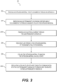
- a method 200 method of operating an extrusion system 20 includes forcing an extrusion material to exit a chamber 25 through an opening 34 at step 202.
- This step 202 may be performed, for example, by the motion of a ram 36 into the chamber 25 to displace a billet 10 of solid material contained therein and to force the extrusion material through an opening 34 that is defined, at least in part, by a die 32.
- the method 200 also includes energizing an electromagnetic winding 50 disposed about the chamber 25 to produce a magnetic field in the extrusion material at step 204.
- the electromagnetic winding 50 is preferably formed as a solenoid including an electrical conductor helically wound about the chamber 25.
- This step 204 may include passing a DC electrical current through the electromagnetic winding 50 at substep 204A.
- a DC electrical current is preferred, although an AC current may be used provided that the frequency of the AC current is chosen to minimize induction heating and to avoid melting the extrusion material.
- DC magnetic fields resulting from the DC electrical current are more effective because they are able to penetrate the entire conductive extrusion material.
- AC fields on the other hand, have a rather shallow skin depth, limiting the penetration depth into the surface of the extrusion material.
- the method 200 also includes reducing flow stress in the extrusion material by the magnetic field in the material at step 206.
- This step utilizes the magnetoplasticity effect, by which a material is altered by dissipating dislocation defect structures by a strong magnetic field.
- the magnetic field preferably has a magnetic flux density of at least 2 Tesla in the extrusion material, although the reduction in the flow stress may depend on other factors such as, for example, the composition of the extrusion material, the temperature, and the pressure applied to the extrusion material.
- the method 200 also includes cooling the extrusion material to maintain the extrusion material in a solid state at step 208.
- the extrusion material is preferably maintained at a temperature where in remains a solid.
- Step 208 may include circulating a cooling fluid into heat conductive communication with the electromagnetic winding 50 to remove heat generated in the electromagnetic winding 50 at sub-step 208A.
- the cooling fluid may be a liquid or a gas and may be, for example, a coolant that is circulated through passages in the tool retainer block 52 and/or through the electromagnetic winding 50 itself.
- the cooling fluid may be cooled to remove the excess heat by traditional means, such as an evaporative cooling system, one or more heat exchangers, and/or using one or more chillers to transfer heat using phase changes of a refrigerant.
Landscapes
- Engineering & Computer Science (AREA)
- Mechanical Engineering (AREA)
- Manufacturing & Machinery (AREA)
- Extrusion Of Metal (AREA)
Claims (7)
- Elektromagnetisches Extrusions-System (20) zum Extrudieren eines Extrusionsmaterials, das umfasst:einen Behälter (22), der eine Kammer (25) zum Aufnehmen des Extrusionsmaterials aufweist;ein Werkzeug (32), das eine Öffnung (34) aufweist, die in Fluidverbindung mit der Kammer (25) steht, damit das Extrusionsmaterial als ein Extrusionsteil (12) darüber austritt;eine elektromagnetische Wicklung (50), die schraubenförmig um die Kammer (25) herum gewickelt und so ausgeführt ist, dass sie einen elektrischen Strom leitet, um ein Magnetfeld zu erzeugen, Fließspannung des Extrusionsmaterials zu reduzieren und eine magnetische Flussdichte von wenigstens 2 Tesla innerhalb des Extrusionsmaterials zu erzeugen;einen Stößel (36), der so ausgeführt ist, dass er das Extrusionsmaterial über die Öffnung (34) ausdrückt, wobei der Behälter (22) die Form eines Bechers mit einer röhrenförmigen Seitenwand (24) hat, die eine Innenfläche (30) bildet und sich in einer axialen Richtung von einer massiven Basis aus erstreckt; unddas Werkzeug (32) so ausgeführt ist, dass es sich mit dem Stößel (36) durch die Kammer (25) hindurch bewegt, wobei sich die Öffnung (34) zwischen einer Außenfläche des Werkzeugs (32) und der Innenfläche (30) der röhrenförmigen Seitenwand (24) der Kammer (25) erstreckt.
- Elektromagnetisches Extrusions-System (20) nach Anspruch 1, wobei die elektromagnetische Wicklung (50) zum Leiten eines Gleichstroms ausgeführt ist.
- Elektromagnetisches Extrusions-System (20) nach Anspruch 1, wobei der Behälter (22) oder/und das Werkzeug (32) ein ferromagnetisches Material umfasst/umfassen, das so ausgeführt ist, dass es das Magnetfeld im Inneren des Extrusionsmaterials verstärkt.
- Elektromagnetisches Extrusions-System (20) nach Anspruch 1, das des Weiteren einen Werkzeug- Halteblock umfasst, der den Behälter (22) umgibt; und
wobei die elektromagnetische Wicklung (50) innerhalb des Werkzeughalteblocks angeordnet ist. - Elektromagnetisches Extrusions-System (20) nach Anspruch 1, wobei das System zum Extrudieren von Metall ausgeführt ist.
- Verfahren zum Betreiben eines Extrusions-Systems (20) mit den in einem der Ansprüche 1 bis 5 definierten Merkmalen, wobei das Verfahren umfasst:Ausdrücken eines Extrusionsmaterials aus einer Kammer (25) über eine Öffnung (34);und Erregen einer elektromagnetischen Wicklung (50), die um die Kammer (25) herum angeordnet ist, um ein Magnetfeld in dem Extrusionsmaterial zu erzeugen; sowieReduzieren von Fließspannung in dem Material durch das Magnetfeld in dem Extrusionsmaterial, wobei das Magnetfeld eine magnetische Flussdichte von wenigstens 2 Tesla innerhalb des Extrusionsmaterials aufweist.
- Verfahren zum Betreiben eines Extrusions-Systems (20) nach Anspruch 7, wobei der Schritt des Erregens einer um die Kammer herum angeordneten elektromagnetischen Wicklung (50) Leiten eines elektrischen Gleichstroms durch die elektromagnetische Wicklung (50) hindurch umfasst.
Applications Claiming Priority (2)
| Application Number | Priority Date | Filing Date | Title |
|---|---|---|---|
| US201762552893P | 2017-12-15 | 2017-12-15 | |
| PCT/US2018/049087 WO2019118018A1 (en) | 2017-12-15 | 2018-08-31 | Electromagnetic extrusion |
Publications (3)
| Publication Number | Publication Date |
|---|---|
| EP3723921A1 EP3723921A1 (de) | 2020-10-21 |
| EP3723921A4 EP3723921A4 (de) | 2020-10-21 |
| EP3723921B1 true EP3723921B1 (de) | 2023-03-22 |
Family
ID=66820889
Family Applications (1)
| Application Number | Title | Priority Date | Filing Date |
|---|---|---|---|
| EP18889363.0A Active EP3723921B1 (de) | 2017-12-15 | 2018-08-31 | Elektromagnetische extrusion und deren betriebsverfahren |
Country Status (6)
| Country | Link |
|---|---|
| US (1) | US11951519B2 (de) |
| EP (1) | EP3723921B1 (de) |
| CN (1) | CN111479639A (de) |
| HU (1) | HUE061924T2 (de) |
| PL (1) | PL3723921T3 (de) |
| WO (1) | WO2019118018A1 (de) |
Families Citing this family (2)
| Publication number | Priority date | Publication date | Assignee | Title |
|---|---|---|---|---|
| CN115007720A (zh) * | 2022-06-29 | 2022-09-06 | 凯米特新材料科技有限公司 | 光伏太阳能节能边框一模多孔挤压设备 |
| CN117531860A (zh) * | 2023-11-27 | 2024-02-09 | 华中科技大学 | 一种磁场辅助轻合金挤压扭转变形装置及方法 |
Family Cites Families (22)
| Publication number | Priority date | Publication date | Assignee | Title |
|---|---|---|---|---|
| US2870907A (en) * | 1944-07-22 | 1959-01-27 | Edward C Creutz | Forming tubes and rods of uranium metal by extrusion |
| US3774890A (en) * | 1957-06-27 | 1973-11-27 | Jerome H Lemelson | Apparatus for working moldable material |
| US3874207A (en) * | 1957-10-22 | 1975-04-01 | Jerome H Lemelson | Extrusion apparatus |
| US5360329A (en) * | 1957-10-22 | 1994-11-01 | Lemelson Jerome H | Molding/extrusion apparatus with temperature and flow control |
| US3060560A (en) * | 1959-01-12 | 1962-10-30 | Int Harvester Co | Method for cold extruding high density articles from ferrous metal powder |
| US3668748A (en) * | 1969-09-12 | 1972-06-13 | American Standard Inc | Process for producing whisker-reinforced metal matrix composites by liquid-phase consolidation |
| US3744890A (en) | 1970-10-09 | 1973-07-10 | Ricoh Kk | System for searching for desired information |
| GB1425915A (en) | 1972-06-22 | 1976-02-25 | British Steel Corp | Rolling mills |
| US3928995A (en) | 1973-12-27 | 1975-12-30 | Western Electric Co | Method of and apparatus for producing articles having high magnetic permeability from billets of temporarily magnetizable (i.e., soft magnetic) material |
| US4346578A (en) * | 1976-12-30 | 1982-08-31 | Harrison Nelson K | Extrusion press and method |
| DE2823001C2 (de) * | 1978-05-26 | 1984-08-23 | Glacier Gmbh Deva Werke, 3570 Stadtallendorf | Anwendung eines Strangpreßverfahrens auf höher-molekulare Verbindungen |
| FI64251C (fi) | 1979-05-11 | 1983-10-10 | Nokia Oy Ab | Spruthuvud foer straengsprutmaskin |
| JPS56120012A (en) | 1980-02-27 | 1981-09-21 | Fujikura Ltd | Method of manufacturing crosslinked insulated cable |
| US6138355A (en) * | 1998-12-01 | 2000-10-31 | Grassi; John R. | Method for manufacturing wheels |
| EP1264646A1 (de) * | 2001-06-07 | 2002-12-11 | Alcan Technology & Management AG | Vorrichtung und Verfahren zur Herstellung eines Metallprofilstranges |
| CN1223414C (zh) * | 2001-12-04 | 2005-10-19 | 财团法人工业技术研究院 | 制造流体轴承的装置及其方法 |
| US20140225467A1 (en) * | 2011-08-31 | 2014-08-14 | Siemens Aktiengesellschaft | Magnetic gear mechanism with coils around permanently excited magnet poles |
| CA2882592C (en) * | 2012-09-21 | 2020-04-14 | Rio Tinto Alcan International Limited | Aluminum alloy composition and method |
| ES2556267B1 (es) * | 2014-07-14 | 2016-11-03 | Obrascon Huarte Lain, S.A. | Macroaglomerado drenante con capacidad portante, su uso para pavimentación y fabricación de capas de rodadura |
| KR101577333B1 (ko) | 2014-12-03 | 2015-12-14 | 부산대학교 산학협력단 | 전기소성효과를 이용한 초고속 성형 방법 |
| US10460871B2 (en) * | 2015-10-30 | 2019-10-29 | GM Global Technology Operations LLC | Method for fabricating non-planar magnet |
| CN105499292B (zh) * | 2016-01-19 | 2017-07-11 | 西安建筑科技大学 | 磁致塑性变断面转角挤压制备细晶的装置及其方法 |
-
2018
- 2018-08-31 EP EP18889363.0A patent/EP3723921B1/de active Active
- 2018-08-31 WO PCT/US2018/049087 patent/WO2019118018A1/en not_active Ceased
- 2018-08-31 HU HUE18889363A patent/HUE061924T2/hu unknown
- 2018-08-31 CN CN201880080141.5A patent/CN111479639A/zh active Pending
- 2018-08-31 US US16/771,389 patent/US11951519B2/en active Active
- 2018-08-31 PL PL18889363.0T patent/PL3723921T3/pl unknown
Also Published As
| Publication number | Publication date |
|---|---|
| PL3723921T3 (pl) | 2023-08-14 |
| EP3723921A1 (de) | 2020-10-21 |
| US20200391265A1 (en) | 2020-12-17 |
| EP3723921A4 (de) | 2020-10-21 |
| US11951519B2 (en) | 2024-04-09 |
| HUE061924T2 (hu) | 2023-09-28 |
| CN111479639A (zh) | 2020-07-31 |
| WO2019118018A1 (en) | 2019-06-20 |
Similar Documents
| Publication | Publication Date | Title |
|---|---|---|
| DE10240876B4 (de) | Verfahren sowie Vorrichtung zum Formen eines Metallelements | |
| US8499598B2 (en) | Electromagnetic forming of metallic glasses using a capacitive discharge and magnetic field | |
| EP1407462B1 (de) | Verfahren zur herstellung von nanokristallinen magnetkernen sowie vorrichtung zur durchführung des verfahrens | |
| US11951519B2 (en) | Electromagnetic extrusion | |
| KR101664726B1 (ko) | 희토류 자석의 제조 방법 | |
| US2722589A (en) | Method and apparatus for uniformly heating intermittently moving metallic material | |
| DE102016107950A1 (de) | Verfahren zum Fertigen eines hohlen Bauteils, Bauteil und Presse zum Fertigen eines hohlen Bauteils | |
| EP2136940B1 (de) | Verfahren zur bereitstellung eines elektromagnetgehäuses | |
| DE102015116661B3 (de) | Temperaturkalibrator und Verfahren zum Kühlen und Heizen eines Temperaturkalibrators | |
| US20170326614A1 (en) | Ultra-high-speed forming method using electroplasticity effect | |
| DE102016107946B4 (de) | Verfahren zum Fertigen eines hohlen Bauteils, Bauteil und Presse zum Fertigen eines hohlen Bauteils | |
| EP1536899B1 (de) | Verfahren zur herstellung einer metallschale und zum dienen als rohling ausgeführter becher | |
| DE112018002646T5 (de) | Proportionalsolenoid, Verfahren zur Herstellung desselben und Verfahren zum Steuern von Eigenschaften des Proportionalsolenoids | |
| DE102014213595A1 (de) | Vorrichtung und Verfahren zur Herstellung eines Stators einer elektrischen Maschine | |
| US4369077A (en) | Method of manufacturing an electromagnetic core | |
| US3928995A (en) | Method of and apparatus for producing articles having high magnetic permeability from billets of temporarily magnetizable (i.e., soft magnetic) material | |
| US1818054A (en) | Magnetic material | |
| JP2547383B2 (ja) | 磁性を利用した物品の製造方法と製造装置 | |
| DE102009039759A1 (de) | Verfahren und Vorrichtung zum Strangpressen und nachfolgender elektromagnetischer Umformung | |
| JP2016081942A (ja) | 希土類磁石の製造方法 | |
| DE102014213593B4 (de) | Vorrichtung und Verfahren zur Herstellung eines Stators einer elektrischen Maschine | |
| DE19939399A1 (de) | Glühvorrichtung | |
| CN116603878B (zh) | 一种镁合金丝材电磁拉拔方法及其装置 | |
| DE102018122441A1 (de) | Geschweisstes hohlraumventil mit kleiner wärmeeinflusszone und verfahren zur herstellung | |
| Hawkins et al. | Effect of warm extrusion on the structure and properties of low-carbon steels |
Legal Events
| Date | Code | Title | Description |
|---|---|---|---|
| STAA | Information on the status of an ep patent application or granted ep patent |
Free format text: STATUS: THE INTERNATIONAL PUBLICATION HAS BEEN MADE |
|
| PUAI | Public reference made under article 153(3) epc to a published international application that has entered the european phase |
Free format text: ORIGINAL CODE: 0009012 |
|
| STAA | Information on the status of an ep patent application or granted ep patent |
Free format text: STATUS: REQUEST FOR EXAMINATION WAS MADE |
|
| 17P | Request for examination filed |
Effective date: 20200619 |
|
| A4 | Supplementary search report drawn up and despatched |
Effective date: 20200805 |
|
| AK | Designated contracting states |
Kind code of ref document: A1 Designated state(s): AL AT BE BG CH CY CZ DE DK EE ES FI FR GB GR HR HU IE IS IT LI LT LU LV MC MK MT NL NO PL PT RO RS SE SI SK SM TR |
|
| AX | Request for extension of the european patent |
Extension state: BA ME |
|
| DAV | Request for validation of the european patent (deleted) | ||
| DAX | Request for extension of the european patent (deleted) | ||
| STAA | Information on the status of an ep patent application or granted ep patent |
Free format text: STATUS: EXAMINATION IS IN PROGRESS |
|
| 17Q | First examination report despatched |
Effective date: 20210716 |
|
| REG | Reference to a national code |
Ref country code: DE Ref legal event code: R079 Ref document number: 602018047612 Country of ref document: DE Free format text: PREVIOUS MAIN CLASS: B21C0023000000 Ipc: B22F0003200000 |
|
| GRAP | Despatch of communication of intention to grant a patent |
Free format text: ORIGINAL CODE: EPIDOSNIGR1 |
|
| STAA | Information on the status of an ep patent application or granted ep patent |
Free format text: STATUS: GRANT OF PATENT IS INTENDED |
|
| RIC1 | Information provided on ipc code assigned before grant |
Ipc: B21C 23/03 20060101ALI20220310BHEP Ipc: B21C 27/00 20060101ALI20220310BHEP Ipc: B21C 23/21 20060101ALI20220310BHEP Ipc: B30B 11/26 20060101ALI20220310BHEP Ipc: B29C 48/09 20190101ALI20220310BHEP Ipc: B29C 48/14 20190101ALI20220310BHEP Ipc: B21C 29/02 20060101ALI20220310BHEP Ipc: B22F 3/20 20060101AFI20220310BHEP |
|
| INTG | Intention to grant announced |
Effective date: 20220413 |
|
| RIN1 | Information on inventor provided before grant (corrected) |
Inventor name: LUDTKA, GERARD MICHAEL Inventor name: STEINEBACH, EDWARD KARL Inventor name: BRADY, JEREMIAH JOHN |
|
| GRAJ | Information related to disapproval of communication of intention to grant by the applicant or resumption of examination proceedings by the epo deleted |
Free format text: ORIGINAL CODE: EPIDOSDIGR1 |
|
| STAA | Information on the status of an ep patent application or granted ep patent |
Free format text: STATUS: EXAMINATION IS IN PROGRESS |
|
| INTC | Intention to grant announced (deleted) | ||
| GRAP | Despatch of communication of intention to grant a patent |
Free format text: ORIGINAL CODE: EPIDOSNIGR1 |
|
| STAA | Information on the status of an ep patent application or granted ep patent |
Free format text: STATUS: GRANT OF PATENT IS INTENDED |
|
| INTG | Intention to grant announced |
Effective date: 20220930 |
|
| GRAS | Grant fee paid |
Free format text: ORIGINAL CODE: EPIDOSNIGR3 |
|
| GRAA | (expected) grant |
Free format text: ORIGINAL CODE: 0009210 |
|
| STAA | Information on the status of an ep patent application or granted ep patent |
Free format text: STATUS: THE PATENT HAS BEEN GRANTED |
|
| AK | Designated contracting states |
Kind code of ref document: B1 Designated state(s): AL AT BE BG CH CY CZ DE DK EE ES FI FR GB GR HR HU IE IS IT LI LT LU LV MC MK MT NL NO PL PT RO RS SE SI SK SM TR |
|
| REG | Reference to a national code |
Ref country code: GB Ref legal event code: FG4D |
|
| REG | Reference to a national code |
Ref country code: CH Ref legal event code: EP |
|
| REG | Reference to a national code |
Ref country code: IE Ref legal event code: FG4D |
|
| REG | Reference to a national code |
Ref country code: DE Ref legal event code: R096 Ref document number: 602018047612 Country of ref document: DE |
|
| REG | Reference to a national code |
Ref country code: AT Ref legal event code: REF Ref document number: 1554975 Country of ref document: AT Kind code of ref document: T Effective date: 20230415 |
|
| REG | Reference to a national code |
Ref country code: LT Ref legal event code: MG9D |
|
| REG | Reference to a national code |
Ref country code: NL Ref legal event code: MP Effective date: 20230322 |
|
| PG25 | Lapsed in a contracting state [announced via postgrant information from national office to epo] |
Ref country code: RS Free format text: LAPSE BECAUSE OF FAILURE TO SUBMIT A TRANSLATION OF THE DESCRIPTION OR TO PAY THE FEE WITHIN THE PRESCRIBED TIME-LIMIT Effective date: 20230322 Ref country code: NO Free format text: LAPSE BECAUSE OF FAILURE TO SUBMIT A TRANSLATION OF THE DESCRIPTION OR TO PAY THE FEE WITHIN THE PRESCRIBED TIME-LIMIT Effective date: 20230622 Ref country code: LV Free format text: LAPSE BECAUSE OF FAILURE TO SUBMIT A TRANSLATION OF THE DESCRIPTION OR TO PAY THE FEE WITHIN THE PRESCRIBED TIME-LIMIT Effective date: 20230322 Ref country code: LT Free format text: LAPSE BECAUSE OF FAILURE TO SUBMIT A TRANSLATION OF THE DESCRIPTION OR TO PAY THE FEE WITHIN THE PRESCRIBED TIME-LIMIT Effective date: 20230322 Ref country code: HR Free format text: LAPSE BECAUSE OF FAILURE TO SUBMIT A TRANSLATION OF THE DESCRIPTION OR TO PAY THE FEE WITHIN THE PRESCRIBED TIME-LIMIT Effective date: 20230322 |
|
| REG | Reference to a national code |
Ref country code: AT Ref legal event code: MK05 Ref document number: 1554975 Country of ref document: AT Kind code of ref document: T Effective date: 20230322 |
|
| PG25 | Lapsed in a contracting state [announced via postgrant information from national office to epo] |
Ref country code: SE Free format text: LAPSE BECAUSE OF FAILURE TO SUBMIT A TRANSLATION OF THE DESCRIPTION OR TO PAY THE FEE WITHIN THE PRESCRIBED TIME-LIMIT Effective date: 20230322 Ref country code: NL Free format text: LAPSE BECAUSE OF FAILURE TO SUBMIT A TRANSLATION OF THE DESCRIPTION OR TO PAY THE FEE WITHIN THE PRESCRIBED TIME-LIMIT Effective date: 20230322 Ref country code: GR Free format text: LAPSE BECAUSE OF FAILURE TO SUBMIT A TRANSLATION OF THE DESCRIPTION OR TO PAY THE FEE WITHIN THE PRESCRIBED TIME-LIMIT Effective date: 20230623 Ref country code: FI Free format text: LAPSE BECAUSE OF FAILURE TO SUBMIT A TRANSLATION OF THE DESCRIPTION OR TO PAY THE FEE WITHIN THE PRESCRIBED TIME-LIMIT Effective date: 20230322 |
|
| REG | Reference to a national code |
Ref country code: HU Ref legal event code: AG4A Ref document number: E061924 Country of ref document: HU |
|
| PG25 | Lapsed in a contracting state [announced via postgrant information from national office to epo] |
Ref country code: SM Free format text: LAPSE BECAUSE OF FAILURE TO SUBMIT A TRANSLATION OF THE DESCRIPTION OR TO PAY THE FEE WITHIN THE PRESCRIBED TIME-LIMIT Effective date: 20230322 Ref country code: RO Free format text: LAPSE BECAUSE OF FAILURE TO SUBMIT A TRANSLATION OF THE DESCRIPTION OR TO PAY THE FEE WITHIN THE PRESCRIBED TIME-LIMIT Effective date: 20230322 Ref country code: PT Free format text: LAPSE BECAUSE OF FAILURE TO SUBMIT A TRANSLATION OF THE DESCRIPTION OR TO PAY THE FEE WITHIN THE PRESCRIBED TIME-LIMIT Effective date: 20230724 Ref country code: ES Free format text: LAPSE BECAUSE OF FAILURE TO SUBMIT A TRANSLATION OF THE DESCRIPTION OR TO PAY THE FEE WITHIN THE PRESCRIBED TIME-LIMIT Effective date: 20230322 Ref country code: EE Free format text: LAPSE BECAUSE OF FAILURE TO SUBMIT A TRANSLATION OF THE DESCRIPTION OR TO PAY THE FEE WITHIN THE PRESCRIBED TIME-LIMIT Effective date: 20230322 Ref country code: AT Free format text: LAPSE BECAUSE OF FAILURE TO SUBMIT A TRANSLATION OF THE DESCRIPTION OR TO PAY THE FEE WITHIN THE PRESCRIBED TIME-LIMIT Effective date: 20230322 |
|
| PGFP | Annual fee paid to national office [announced via postgrant information from national office to epo] |
Ref country code: CZ Payment date: 20230818 Year of fee payment: 6 |
|
| PG25 | Lapsed in a contracting state [announced via postgrant information from national office to epo] |
Ref country code: SK Free format text: LAPSE BECAUSE OF FAILURE TO SUBMIT A TRANSLATION OF THE DESCRIPTION OR TO PAY THE FEE WITHIN THE PRESCRIBED TIME-LIMIT Effective date: 20230322 Ref country code: IS Free format text: LAPSE BECAUSE OF FAILURE TO SUBMIT A TRANSLATION OF THE DESCRIPTION OR TO PAY THE FEE WITHIN THE PRESCRIBED TIME-LIMIT Effective date: 20230722 |
|
| PGFP | Annual fee paid to national office [announced via postgrant information from national office to epo] |
Ref country code: HU Payment date: 20230720 Year of fee payment: 6 |
|
| REG | Reference to a national code |
Ref country code: DE Ref legal event code: R097 Ref document number: 602018047612 Country of ref document: DE |
|
| PLBE | No opposition filed within time limit |
Free format text: ORIGINAL CODE: 0009261 |
|
| STAA | Information on the status of an ep patent application or granted ep patent |
Free format text: STATUS: NO OPPOSITION FILED WITHIN TIME LIMIT |
|
| PG25 | Lapsed in a contracting state [announced via postgrant information from national office to epo] |
Ref country code: SI Free format text: LAPSE BECAUSE OF FAILURE TO SUBMIT A TRANSLATION OF THE DESCRIPTION OR TO PAY THE FEE WITHIN THE PRESCRIBED TIME-LIMIT Effective date: 20230322 Ref country code: DK Free format text: LAPSE BECAUSE OF FAILURE TO SUBMIT A TRANSLATION OF THE DESCRIPTION OR TO PAY THE FEE WITHIN THE PRESCRIBED TIME-LIMIT Effective date: 20230322 |
|
| 26N | No opposition filed |
Effective date: 20240102 |
|
| PG25 | Lapsed in a contracting state [announced via postgrant information from national office to epo] |
Ref country code: MC Free format text: LAPSE BECAUSE OF FAILURE TO SUBMIT A TRANSLATION OF THE DESCRIPTION OR TO PAY THE FEE WITHIN THE PRESCRIBED TIME-LIMIT Effective date: 20230322 |
|
| REG | Reference to a national code |
Ref country code: CH Ref legal event code: PL |
|
| PG25 | Lapsed in a contracting state [announced via postgrant information from national office to epo] |
Ref country code: MC Free format text: LAPSE BECAUSE OF FAILURE TO SUBMIT A TRANSLATION OF THE DESCRIPTION OR TO PAY THE FEE WITHIN THE PRESCRIBED TIME-LIMIT Effective date: 20230322 |
|
| PG25 | Lapsed in a contracting state [announced via postgrant information from national office to epo] |
Ref country code: LU Free format text: LAPSE BECAUSE OF NON-PAYMENT OF DUE FEES Effective date: 20230831 |
|
| GBPC | Gb: european patent ceased through non-payment of renewal fee |
Effective date: 20230831 |
|
| PG25 | Lapsed in a contracting state [announced via postgrant information from national office to epo] |
Ref country code: LU Free format text: LAPSE BECAUSE OF NON-PAYMENT OF DUE FEES Effective date: 20230831 Ref country code: CH Free format text: LAPSE BECAUSE OF NON-PAYMENT OF DUE FEES Effective date: 20230831 |
|
| REG | Reference to a national code |
Ref country code: BE Ref legal event code: MM Effective date: 20230831 |
|
| REG | Reference to a national code |
Ref country code: IE Ref legal event code: MM4A |
|
| PG25 | Lapsed in a contracting state [announced via postgrant information from national office to epo] |
Ref country code: IT Free format text: LAPSE BECAUSE OF FAILURE TO SUBMIT A TRANSLATION OF THE DESCRIPTION OR TO PAY THE FEE WITHIN THE PRESCRIBED TIME-LIMIT Effective date: 20230322 |
|
| PG25 | Lapsed in a contracting state [announced via postgrant information from national office to epo] |
Ref country code: IE Free format text: LAPSE BECAUSE OF NON-PAYMENT OF DUE FEES Effective date: 20230831 |
|
| PG25 | Lapsed in a contracting state [announced via postgrant information from national office to epo] |
Ref country code: GB Free format text: LAPSE BECAUSE OF NON-PAYMENT OF DUE FEES Effective date: 20230831 |
|
| PG25 | Lapsed in a contracting state [announced via postgrant information from national office to epo] |
Ref country code: IE Free format text: LAPSE BECAUSE OF NON-PAYMENT OF DUE FEES Effective date: 20230831 Ref country code: FR Free format text: LAPSE BECAUSE OF NON-PAYMENT OF DUE FEES Effective date: 20230831 Ref country code: GB Free format text: LAPSE BECAUSE OF NON-PAYMENT OF DUE FEES Effective date: 20230831 |
|
| PGFP | Annual fee paid to national office [announced via postgrant information from national office to epo] |
Ref country code: PL Payment date: 20240620 Year of fee payment: 7 |
|
| PG25 | Lapsed in a contracting state [announced via postgrant information from national office to epo] |
Ref country code: BE Free format text: LAPSE BECAUSE OF NON-PAYMENT OF DUE FEES Effective date: 20230831 |
|
| PGFP | Annual fee paid to national office [announced via postgrant information from national office to epo] |
Ref country code: DE Payment date: 20240702 Year of fee payment: 7 |
|
| PG25 | Lapsed in a contracting state [announced via postgrant information from national office to epo] |
Ref country code: BG Free format text: LAPSE BECAUSE OF FAILURE TO SUBMIT A TRANSLATION OF THE DESCRIPTION OR TO PAY THE FEE WITHIN THE PRESCRIBED TIME-LIMIT Effective date: 20230322 |
|
| PG25 | Lapsed in a contracting state [announced via postgrant information from national office to epo] |
Ref country code: BG Free format text: LAPSE BECAUSE OF FAILURE TO SUBMIT A TRANSLATION OF THE DESCRIPTION OR TO PAY THE FEE WITHIN THE PRESCRIBED TIME-LIMIT Effective date: 20230322 |
|
| PG25 | Lapsed in a contracting state [announced via postgrant information from national office to epo] |
Ref country code: HU Free format text: LAPSE BECAUSE OF NON-PAYMENT OF DUE FEES Effective date: 20240901 |
|
| PG25 | Lapsed in a contracting state [announced via postgrant information from national office to epo] |
Ref country code: CZ Free format text: LAPSE BECAUSE OF NON-PAYMENT OF DUE FEES Effective date: 20240831 |
|
| PG25 | Lapsed in a contracting state [announced via postgrant information from national office to epo] |
Ref country code: CY Free format text: LAPSE BECAUSE OF FAILURE TO SUBMIT A TRANSLATION OF THE DESCRIPTION OR TO PAY THE FEE WITHIN THE PRESCRIBED TIME-LIMIT; INVALID AB INITIO Effective date: 20180831 |
|
| PG25 | Lapsed in a contracting state [announced via postgrant information from national office to epo] |
Ref country code: TR Free format text: LAPSE BECAUSE OF FAILURE TO SUBMIT A TRANSLATION OF THE DESCRIPTION OR TO PAY THE FEE WITHIN THE PRESCRIBED TIME-LIMIT Effective date: 20230322 |
|
| REG | Reference to a national code |
Ref country code: DE Ref legal event code: R119 Ref document number: 602018047612 Country of ref document: DE |