EP3723915B1 - Siebherstellverfahren - Google Patents
Siebherstellverfahren Download PDFInfo
- Publication number
- EP3723915B1 EP3723915B1 EP18789113.0A EP18789113A EP3723915B1 EP 3723915 B1 EP3723915 B1 EP 3723915B1 EP 18789113 A EP18789113 A EP 18789113A EP 3723915 B1 EP3723915 B1 EP 3723915B1
- Authority
- EP
- European Patent Office
- Prior art keywords
- profiled bars
- punches
- recesses
- bar
- bars
- Prior art date
- Legal status (The legal status is an assumption and is not a legal conclusion. Google has not performed a legal analysis and makes no representation as to the accuracy of the status listed.)
- Active
Links
Images
Classifications
-
- B—PERFORMING OPERATIONS; TRANSPORTING
- B07—SEPARATING SOLIDS FROM SOLIDS; SORTING
- B07B—SEPARATING SOLIDS FROM SOLIDS BY SIEVING, SCREENING, SIFTING OR BY USING GAS CURRENTS; SEPARATING BY OTHER DRY METHODS APPLICABLE TO BULK MATERIAL, e.g. LOOSE ARTICLES FIT TO BE HANDLED LIKE BULK MATERIAL
- B07B1/00—Sieving, screening, sifting, or sorting solid materials using networks, gratings, grids, or the like
- B07B1/46—Constructional details of screens in general; Cleaning or heating of screens
- B07B1/4609—Constructional details of screens in general; Cleaning or heating of screens constructional details of screening surfaces or meshes
- B07B1/4618—Manufacturing of screening surfaces
-
- B—PERFORMING OPERATIONS; TRANSPORTING
- B01—PHYSICAL OR CHEMICAL PROCESSES OR APPARATUS IN GENERAL
- B01D—SEPARATION
- B01D33/00—Filters with filtering elements which move during the filtering operation
- B01D33/06—Filters with filtering elements which move during the filtering operation with rotary cylindrical filtering surfaces, e.g. hollow drums
- B01D33/067—Construction of the filtering drums, e.g. mounting or sealing arrangements
-
- B—PERFORMING OPERATIONS; TRANSPORTING
- B01—PHYSICAL OR CHEMICAL PROCESSES OR APPARATUS IN GENERAL
- B01D—SEPARATION
- B01D33/00—Filters with filtering elements which move during the filtering operation
- B01D33/06—Filters with filtering elements which move during the filtering operation with rotary cylindrical filtering surfaces, e.g. hollow drums
- B01D33/073—Filters with filtering elements which move during the filtering operation with rotary cylindrical filtering surfaces, e.g. hollow drums arranged for inward flow filtration
-
- B—PERFORMING OPERATIONS; TRANSPORTING
- B07—SEPARATING SOLIDS FROM SOLIDS; SORTING
- B07B—SEPARATING SOLIDS FROM SOLIDS BY SIEVING, SCREENING, SIFTING OR BY USING GAS CURRENTS; SEPARATING BY OTHER DRY METHODS APPLICABLE TO BULK MATERIAL, e.g. LOOSE ARTICLES FIT TO BE HANDLED LIKE BULK MATERIAL
- B07B1/00—Sieving, screening, sifting, or sorting solid materials using networks, gratings, grids, or the like
- B07B1/12—Apparatus having only parallel elements
-
- B—PERFORMING OPERATIONS; TRANSPORTING
- B07—SEPARATING SOLIDS FROM SOLIDS; SORTING
- B07B—SEPARATING SOLIDS FROM SOLIDS BY SIEVING, SCREENING, SIFTING OR BY USING GAS CURRENTS; SEPARATING BY OTHER DRY METHODS APPLICABLE TO BULK MATERIAL, e.g. LOOSE ARTICLES FIT TO BE HANDLED LIKE BULK MATERIAL
- B07B1/00—Sieving, screening, sifting, or sorting solid materials using networks, gratings, grids, or the like
- B07B1/18—Drum screens
-
- D—TEXTILES; PAPER
- D21—PAPER-MAKING; PRODUCTION OF CELLULOSE
- D21D—TREATMENT OF THE MATERIALS BEFORE PASSING TO THE PAPER-MAKING MACHINE
- D21D5/00—Purification of the pulp suspension by mechanical means; Apparatus therefor
- D21D5/02—Straining or screening the pulp
- D21D5/16—Cylinders and plates for screens
-
- B—PERFORMING OPERATIONS; TRANSPORTING
- B01—PHYSICAL OR CHEMICAL PROCESSES OR APPARATUS IN GENERAL
- B01D—SEPARATION
- B01D2201/00—Details relating to filtering apparatus
- B01D2201/28—Position of the filtering element
- B01D2201/287—Filtering elements with a vertical or inclined rotation or symmetry axis
-
- B—PERFORMING OPERATIONS; TRANSPORTING
- B01—PHYSICAL OR CHEMICAL PROCESSES OR APPARATUS IN GENERAL
- B01D—SEPARATION
- B01D29/00—Filters with filtering elements stationary during filtration, e.g. pressure or suction filters, not covered by groups B01D24/00 - B01D27/00; Filtering elements therefor
- B01D29/44—Edge filtering elements, i.e. using contiguous impervious surfaces
- B01D29/445—Bar screens
Definitions
- the invention relates to a method for producing a cylindrical screening device with a large number of profiled bars, in which a plurality of ring-shaped bar holders which run perpendicular to the cylinder axis and are spaced apart from one another are provided on the outside with open-edged recesses, the shape of which corresponds essentially to the bar feet of the profiled bars and which are slightly larger than the rod feet and in which the profile rods are inserted into the recesses parallel to one another and parallel to the cylinder axis.
- cylindrical screening devices that can be produced by the method of this type is the screening of fibrous suspensions, as is carried out in pressure screens in the paper-making industry.
- the fibers contained in the suspension should pass through the screen, while the unwanted solid components are rejected at the gap and guided out of the screening device again.
- openings have an essentially oblong shape, i.e. slots or gaps, fibrous particles can pass through more easily than cubic ones, even if both types should be of a similar size.
- a possible method to produce such screen baskets shows the DE 44 35 538 A1 , in which the profile bars are clamped by plastic deformation of the c-shaped retaining rings provided with depressions for the bars.
- profile rods that are particularly suitable for such manufacturing processes are used. With the help of this process, it was possible to make production significantly cheaper.
- the method is used on strainer baskets where the bars are inserted on the outside edge of the retaining rings. Such an arrangement of the rods is chosen when the suspension is to pass through the slots from the outside to the inside (centripetal mode of operation).
- the radius of curvature of the retaining rings is increased.
- the object of the invention is to reduce the production costs while improving the strength and increasing the service life of the centripetal screening device.
- the rod holder Since the rod holder is already in the form of a ring and is generally designed in one piece, manufacture is simplified considerably. In addition to an exact cylindrical shape, this results in a high degree of accuracy in the recesses and thus also in the screen openings.
- the profile bars are fixed in the recesses of the bar holders exclusively via the clamping that occurs when the profile bars are pressed radially.
- the profile bars of the bar holders must be fixed in their recesses by welding, gluing or similar.
- the inside of the rod holder is not exposed to any supporting or bending forces during the radial pressing of the profile rods, which protects them.
- Production is particularly simple if the profiled bars are pressed radially by means of a plurality of dies acting radially from the outside on the profiled bars.
- stamps should preferably be distributed at equal distances around the circumference of the rod holders.
- the pressing surface of the stamp pointing in the direction of the profile bars should be concave, this pressing surface advantageously being formed perpendicularly to the cylinder axis by a circular segment whose radius corresponds to the outer radius of the finished, cylindrical screening device. This makes it possible to distribute the forces increasingly more evenly on the radial outside of the rod holders during pressing.
- the arrangement is simplified if the stamps each act on a plurality of profile bars.
- the punches should be guided so as to be radially movable, at least during the radial pressing, and/or be fixed axially to the cylinder axis.
- the rod holders 3 are produced as one-piece rings, for example by means of laser cutting. This is the basis for a high dimensional accuracy of the screen basket.
- the rod holders 3 On the outside, the rod holders 3 have a multiplicity of evenly distributed recesses 4 for the profile rods 1. These recesses 4 offer according to Figure 3a enough play so that the profile bars 1 can be pushed axially through them without any problems.
- the screen basket prefabricated in this way consists of profile bars 1 running parallel to the cylinder axis 2 , which are held by a plurality of bar holders 3 which are spaced apart axially and run perpendicularly to the cylinder axis 2 .
- the screen openings of the screen basket are formed by the slots of adjacent profile bars 1.
- slits often have a width between 0.05 and 2 mm.
- stamps 5 are arranged evenly distributed, in particular with respect to the rod holders 3, and in particular are directed towards the cylinder axis 2 of the screen basket.
- the punches 5 of adjacent rod holders 3 arranged axially next to one another can also be designed as a common punch 5 .
- the stamps 5 are guided axially and radially in guide grooves.
Landscapes
- Engineering & Computer Science (AREA)
- Chemical & Material Sciences (AREA)
- Chemical Kinetics & Catalysis (AREA)
- Manufacturing & Machinery (AREA)
- Mechanical Engineering (AREA)
- Paper (AREA)
- Filtering Materials (AREA)
- Combined Means For Separation Of Solids (AREA)
- Separation Of Solids By Using Liquids Or Pneumatic Power (AREA)
Description
- Die Erfindung betrifft ein Verfahren zur Herstellung einer zylindrischen Siebvorrichtung mit einer Vielzahl von Profilstäben, bei dem mehrere ringförmige, senkrecht zur Zylinderachse verlaufende und voneinander beabstandete Stabhalter an der Außenseite mit randoffenen Aussparungen versehen sind, deren Form den Stabfüßen der Profilstäbe im Wesentlichen komplementär entspricht und die geringfügig größer als die Stabfüße sind und bei dem die Profilstäbe parallel zueinander und parallel zur Zylinderachse in die Aussparungen eingesetzt werden.
- Ein bekanntes Beispiel für den Einsatz von zylindrischen Siebvorrichtungen, die nach dem Verfahren dieser Art herstellbar sind, ist das Sortieren von Faserstoffsuspensionen, wie es in Drucksortierern der papiererzeugenden Industrie durchgeführt wird.
- Dabei sollen die in der Suspension enthaltenen Fasern durch das Sieb hindurch treten, während die nicht gewünschten festen Bestandteile an dem Spalt abgewiesen und aus der Siebvorrichtung wieder herausgeleitet werden.
- Dadurch, dass die Öffnungen eine im Wesentlichen längliche Form haben, also Schlitze oder Spalten sind, werden faserige Teilchen leichter durchgelassen als die kubischen, auch wenn beide Arten in ähnlicher Größenordnung vorliegen sollten.
- Mit einer derartigen Sortiertechnologie ist daher ein sehr guter Ausscheidungseffekt von nicht faserigen Störstoffen aus Faserstoffsuspensionen möglich.
- Denkbar ist auch ein Einsatz zur Trennung unterschiedlicher Faserbestandteile, der sogenannten Faserfraktionierung. Voraussetzung ist allerdings eine hohe Präzision der Schlitzform auf der ganzen Siebfläche.
- Ein mögliches Verfahren, um solche Siebkörbe herzustellen, zeigt die
DE 44 35 538 A1 , bei der die Profilstäbe durch plastisches Verformen der mit Vertiefungen für die Stäbe vorgesehenen c-förmigen Halteringe eingeklemmt werden. Hierzu werden für derartige Herstellungsverfahren besonders geeignete Profilstäbe verwendet. Mit Hilfe dieses Verfahrens gelang es, die Herstellung wesentlich zu verbilligen. Das Verfahren wird bei Siebkörben verwendet, bei denen die Stäbe am Außenrand der Halteringe eingesetzt werden. Eine solche Anordnung der Stäbe wird gewählt, wenn die Suspension von außen nach innen die Schlitze passieren soll (zentripetale Fahrweise). - Zur Fixierung der Profilstäbe wird dabei der Krümmungsradius der Halteringe vergrößert.
- Aus der
WO 2015/180955 A1 sowie derUS 2002/130075 A1 , der ein Verfahren zur Herstellung einer zylindrischen Siebvorrichtung gemäß dem Oberbegriff des Anspruchs 1 offenbart, ist es bekannt, die Profilstäbe über radial von außen einwirkende Kräfte in die Aussparungen zu drücken. - Wichtig ist dabei, dass die Dimensionen der Sieböffnungen mit sehr geringen Toleranzen eingehalten werden. Um sie von Verstopfungen frei zu halten, sind zumeist Räumer erforderlich, die in geringerem Abstand an der Siebfläche vorbei bewegt werden und die hydraulische Impulse erzeugen. Siebvorrichtungen für den Einsatz in Drucksortierern müssen daher sehr präzise gefertigt sein und hohen Belastungen standhalten.
- Die Aufgabe der Erfindung ist es den Herstellungsaufwand bei möglichst verbesserter Festigkeit und gesteigerter Lebensdauer der zentripetalen Siebvorrichtung zu vermindern.
- Erfindungsgemäß wurde die Aufgabe mit ein Verfahren gemäß Anspruch 1 gelöst.
- Da der Stabhalter bereits als Ring vorliegt und in der Regel einstückig ausgeführt ist, vereinfacht sich die Herstellung wesentlich. Neben einer exakten zylindrischen Form ergibt sich dadurch eine hohe Genauigkeit bei den Aussparungen und damit auch den Sieböffnungen.
- Infolge des Drückens der Profilstäbe in Richtung der Aussparung der Stabhalter verringert sich der Spielraum zwischen Profilstab und Aussparung, was letztendlich zum Verklemmen beider führt. Neben dem Verklemmen kommt es bei dieser plastischen Verformung auch zu einer Härteverfestigung.
- In vielen Fällen kann es genügen, wenn die Fixierung der Profilstäbe in den Aussparungen der Stabhalter ausschließlich über die sich beim radialen Drücken der Profilstäbe einstellende Klemmung erfolgt.
- Sollte dies nicht genügen, so müssen die Profilstäbe der Stabhalter in deren Aussparungen durch Schweißen, Kleben o.ä. fixiert werden.
- Wenn die Krafteinleitung nur von außen erfolgt, wird die Innenseite der Stabhalter während des radialen Drückens der Profilstäbe keinen Stütz- oder Biegekräften ausgesetzt, was diese schont.
- Besonders einfach gestaltet sich die Herstellung, wenn das radiale Drücken der Profilstäbe über mehrere, radial von außen auf die Profilstäbe einwirkende Stempel erfolgt.
- Diese Stempel sollten vorzugsweise mit gleichem Abstand über den Umfang der Stabhalter verteilt angeordnet sein. Des Weiteren sollte die, in Richtung der Profilstäbe weisende Pressfläche der Stempel konkav ausgebildet sein, wobei diese Pressfläche mit Vorteil senkrecht zur Zylinderachse von einem Kreisabschnitt gebildet wird, dessen Radius dem Außenradius der fertigen, zylindrischen Siebvorrichtung entspricht. Hierdurch gelingt es während des Pressens die Kräfte zunehmend gleichmäßiger auf die radiale Außenseite der Stabhalter zu verteilen.
- Außerdem vereinfacht sich die Anordnung, wenn die Stempel jeweils auf mehrere Profilstäbe einwirken.
- Im Interesse einer exakten Führung sollten die Stempel zumindest während des radialen Drückens radial beweglich geführt und/oder axial zur Zylinderachse fixiert sein.
- Nachfolgend soll die Erfindung an einem Ausführungsbeispiel näher erläutert werden.
- In der beigefügten Zeichnung zeigt:
-
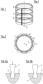
Figur 1 : eine schematische Ansicht eines zylindrischen Siebkorbes; -
Figur 2 : einen schematischen Querschnitt durch diesen und -
Figur 3a +b: die Aussparung 4 mit Profilstab 1 vor und nach dem radialen Drücken. - Die Stabhalter 3 werden als einstückige Ringe beispielsweise mittels Laserschneiden hergestellt. Dies ist die Grundlage für eine hohe Formgenauigkeit des Siebkorbes.
- Auf der Außenseite besitzen die Stabhalter 3 eine Vielzahl gleichmäßig verteilt angeordneter Aussparungen 4 für die Profilstäbe 1. Diese Aussparungen 4 bieten gemäß
Figur 3a ausreichend Spiel, so dass die Profilstäbe 1 problemlos axial durch diese geschoben werden können. - Im Ergebnis besteht der so vorgefertigte Siebkorb aus parallel zur Zylinderachse 2 verlaufenden Profilstäben 1, die über mehrere axial voneinander beabstandete und senkrecht zur Zylinderachse 2 verlaufende Stabhalter 3 gehalten werden.
- Die Sieböffnungen des Siebkorbes werden von den Schlitzen benachbarter Profilstäbe 1 gebildet. In der Praxis haben solche Schlitze oft eine Weite zwischen 0,05 und 2 mm.
- Um die Profilstäbe 1 in den Aussparungen 4 zu fixieren, werden diese radial nach innen in die Stabhalter 3 gedrückt. Hierzu werden in der entsprechenden Herstellungsvorrichtung gemäß
Figur 2 außerhalb des vormontierten Siebkorbes mehrere Stempel 5 insbesondere gegenüber den Stabhaltern 3 gleichmäßig verteilt angeordnet und dabei insbesondere auf die Zylinderachse 2 des Siebkorbes gerichtet. - Dabei können die axial nebeneinander angeordneten Stempel 5 benachbarter Stabhalter 3 auch als ein gemeinsamer Stempel 5 ausgeführt werden.
- Zur Erzeugung eines Formschlusses zwischen Profilstab 1 und Stabhalter 3 werden über die Stempel 5 Druckkräfte auf die Profilstäbe 1 übertragen. Dies muss über den Umfang hinweg möglichst gleichmäßig erfolgen, wobei jeder Stempel 5 jeweils auf mehrere, benachbarte Profilstäbe 1 einwirkt. Hierzu wird die, in Richtung der Profilstäbe 1 weisende Pressfläche aller Stempel 5 jeweils von einem Kreisabschnitt gebildet, dessen Radius dem Außenradius der Siebvorrichtung nach dem Pressvorgang entspricht. Da der von den Profilstäben 1 gebildete Außenradius der Siebvorrichtung vor dem Pressvorgang geringfügig größer als danach ist, besteht am Beginn des Pressvorgangs zwischen den Profilstäben 1 und der Pressfläche im mittleren Teil der Stempels 5 ein kleines Spiel. Dieses Spiel kann beim Beginn des Pressens und den damit verbundenen, geringeren Presskräften in Kauf genommen werden und vermindert sich mit fortschreitender Pressung.
- Dies führt ausgehend von einem relativ großen Spiel für das Einführen der Profilstäbe 1 bei der Vormontage des Siebkorbes (
Figur 3a ) zu einer Verengung der Aussparungen 4 und wegen der komplementären Form zum Festklemmen der Profilstäbe 1 (Figur 3b ). - Diese Umformung erfolgt sehr schonend und gleichmäßig, so dass es an den Stabhaltern 3 zu keiner Überbeanspruchung kommt. Auf eine zusätzliche Befestigung der Profilstäbe 1 kann in der Regel verzichtet werden.
- Während der Druckbeaufschlagung der Profilstäbe 1 werden die Stempel 5 in Führungsnuten axial und radial geführt.
Claims (9)
- Verfahren zur Herstellung einer zylindrischen Siebvorrichtung mit einer Vielzahl von Profilstäben (1), bei dem mehrere ringförmige, senkrecht zur Zylinderachse (2) verlaufende und voneinander beabstandete Stabhalter (3) an der Außenseite mit randoffenen Aussparungen (4) versehen sind, deren Form den Stabfüßen der Profilstäbe (1) im Wesentlichen komplementär entspricht und die geringfügig größer als die Stabfüße sind und bei dem die Profilstäbe (1) parallel zueinander und parallel zur Zylinderachse (2) in die Aussparungen (4) eingesetzt werden, wobei die Profilstäbe (1) über radial von außen auf die Profilstäbe (1) einwirkende Kräfte bis zum Formschluss in die Aussparungen (4) gedrückt werden, wobei das radiale Drücken über mehrere, radial von außen auf die Profilstäbe (1) einwirkende Stempel (5) erfolgt, dadurch gekennzeichnet, dass die Stempel über den Umfang der Stabhalter (3) verteilt angeordnet sind.
- Verfahren nach Anspruch 1, dadurch gekennzeichnet, dass die Fixierung der Profilstäbe (1) in den Aussparungen (4) der Stabhalter (3) ausschließlich über die sich beim radialen Drücken der Profilstäbe (1) einstellende Klemmung erfolgt.
- Verfahren nach Anspruch 1 oder 2, dadurch gekennzeichnet, dass die Innenseite der Stabhalter (3) während des radialen Drückens der Profilstäbe (1) keinen Stütz- oder Biegekräften ausgesetzt wird.
- Verfahren nach einem der vorhergehenden Ansprüche, dadurch gekennzeichnet, dass die Stempel (5) mit gleichem Abstand über den Umfang der Stabhalter (3) verteilt angeordnet sind.
- Verfahren nach einem der vorhergehenden Ansprüche, dadurch gekennzeichnet, dass die Stempel (5) jeweils auf mehrere Profilstäbe (1) einwirken.
- Verfahren nach einem der vorhergehenden Ansprüche, dadurch gekennzeichnet, dass die Stempel (5) radial beweglich geführt sind.
- Verfahren nach Anspruch 6, dadurch gekennzeichnet, dass die Stempel (5) axial zur Zylinderachse (2)fixiert sind.
- Verfahren nach einem der vorhergehenden Ansprüche, dadurch gekennzeichnet, dass die, in Richtung der Profilstäbe (1) weisende Pressfläche der Stempel (5) konkav ausgebildet ist.
- Verfahren nach Anspruch 8, dadurch gekennzeichnet, dass die Pressfläche jedes Stempels (5) senkrecht zur Zylinderachse (2) von einem Kreisabschnitt gebildet wird, dessen Radius dem Außenradius der fertigen Siebvorrichtung entspricht.
Applications Claiming Priority (2)
| Application Number | Priority Date | Filing Date | Title |
|---|---|---|---|
| DE102017129752.9A DE102017129752A1 (de) | 2017-12-13 | 2017-12-13 | Siebherstellverfahren |
| PCT/EP2018/078317 WO2019115061A1 (de) | 2017-12-13 | 2018-10-17 | Siebherstellverfahren |
Publications (2)
| Publication Number | Publication Date |
|---|---|
| EP3723915A1 EP3723915A1 (de) | 2020-10-21 |
| EP3723915B1 true EP3723915B1 (de) | 2023-08-23 |
Family
ID=63896178
Family Applications (1)
| Application Number | Title | Priority Date | Filing Date |
|---|---|---|---|
| EP18789113.0A Active EP3723915B1 (de) | 2017-12-13 | 2018-10-17 | Siebherstellverfahren |
Country Status (9)
| Country | Link |
|---|---|
| US (1) | US11273466B2 (de) |
| EP (1) | EP3723915B1 (de) |
| JP (1) | JP7174052B2 (de) |
| KR (1) | KR20200097767A (de) |
| CN (1) | CN111465456B (de) |
| CA (1) | CA3099123C (de) |
| DE (1) | DE102017129752A1 (de) |
| FI (1) | FI3723915T3 (de) |
| WO (1) | WO2019115061A1 (de) |
Families Citing this family (2)
| Publication number | Priority date | Publication date | Assignee | Title |
|---|---|---|---|---|
| DE102019128878B3 (de) * | 2019-10-25 | 2020-07-30 | Voith Patent Gmbh | Siebzylinder |
| CN112570275B (zh) * | 2020-11-25 | 2021-11-23 | 宣威市金泰资源综合利用有限公司 | 工业固体废弃物无害化处理设备及处理方法 |
Family Cites Families (20)
| Publication number | Priority date | Publication date | Assignee | Title |
|---|---|---|---|---|
| FR2572950B1 (fr) * | 1984-11-12 | 1987-01-23 | Lamort E & M | Perfectionnements aux tamis pour epurateurs et a leur mode de fabrication |
| DE3927748C2 (de) * | 1989-08-23 | 1994-03-10 | Voith Gmbh J M | Verfahren zum Herstellen eines Siebkorbes sowie nach diesem Verfahren hergestellter Siebkorb |
| DE4435538C2 (de) * | 1994-10-05 | 1996-10-02 | Voith Gmbh J M | Verfahren zur Herstellung eines Flachsiebes |
| JP3453612B2 (ja) * | 1994-12-22 | 2003-10-06 | 昭和電工株式会社 | ピンフィンヒートシンクの製造方法 |
| JP3597640B2 (ja) * | 1996-05-24 | 2004-12-08 | 蛇の目ミシン工業株式会社 | ヒートシンク製造方法 |
| US7188733B2 (en) * | 1996-10-03 | 2007-03-13 | Advanced Fiber Technologies (Aft) Trust | Screening device, such as a screen cylinder, and method of manufacture of the screening device |
| CN1080350C (zh) * | 1996-10-03 | 2002-03-06 | Cae筛板公司 | 筛浆装置、例如筛筒以及筛浆装置的制造方法 |
| US20020130075A1 (en) * | 1999-08-19 | 2002-09-19 | Cae Screenplates Oy | Screening device, such as a screen cylinder, and method of manufacture of the screening device |
| US7125491B2 (en) * | 2000-02-03 | 2006-10-24 | Andritz Ag | Screen and process for manufacturing a screen of this kind |
| ATE281554T1 (de) * | 2000-02-19 | 2004-11-15 | Voith Paper Patent Gmbh | Sieb für fasersuspensionen sowie verfahren zu seiner herstellung |
| US6460757B1 (en) * | 2000-11-14 | 2002-10-08 | Newscreen As | Apparatus and method for forming slotted wire screens |
| US20090020461A1 (en) * | 2005-05-09 | 2009-01-22 | Filtration Fibrewall Inc. | Screen Basket with Replaceable Profiled Bars |
| DE102006008172A1 (de) | 2006-02-22 | 2007-08-23 | Voith Patent Gmbh | Verfahren zur Herstellung einer rotationssymmetrischen, insbesondere zylindrischen Siebvorrichtung |
| TW200736458A (en) * | 2006-03-24 | 2007-10-01 | Slit And Hole Industry Co Ltd | A sieve (screen) can prevent sieve bars from falling off |
| FI124683B (fi) * | 2010-10-06 | 2014-12-15 | Aikawa Fiber Technologies Trust | Menetelmä seulasylinterin valmistamiseksi |
| DE102013224528B3 (de) * | 2013-11-29 | 2014-07-24 | Voith Patent Gmbh | Siebherstellverfahren |
| CN203654075U (zh) * | 2013-12-26 | 2014-06-18 | 山东杰锋机械制造有限公司 | 可拆分式压力筛转子 |
| EP3149239A1 (de) * | 2014-05-28 | 2017-04-05 | Voith Patent GmbH | Sieb |
| CN104264523B (zh) * | 2014-10-02 | 2016-04-27 | 江西洪都精工机械有限公司 | 一种高刚性棒筛鼓及其制造方法 |
| CN204509853U (zh) * | 2015-03-13 | 2015-07-29 | 耿德顺 | 组装式压力筛筛鼓 |
-
2017
- 2017-12-13 DE DE102017129752.9A patent/DE102017129752A1/de not_active Withdrawn
-
2018
- 2018-10-17 CN CN201880080088.9A patent/CN111465456B/zh active Active
- 2018-10-17 CA CA3099123A patent/CA3099123C/en active Active
- 2018-10-17 KR KR1020207019948A patent/KR20200097767A/ko active Pending
- 2018-10-17 FI FIEP18789113.0T patent/FI3723915T3/fi active
- 2018-10-17 WO PCT/EP2018/078317 patent/WO2019115061A1/de not_active Ceased
- 2018-10-17 EP EP18789113.0A patent/EP3723915B1/de active Active
- 2018-10-17 JP JP2020532659A patent/JP7174052B2/ja active Active
-
2020
- 2020-06-10 US US16/897,517 patent/US11273466B2/en not_active Expired - Fee Related
Also Published As
| Publication number | Publication date |
|---|---|
| US11273466B2 (en) | 2022-03-15 |
| FI3723915T3 (fi) | 2023-11-08 |
| JP7174052B2 (ja) | 2022-11-17 |
| US20200298278A1 (en) | 2020-09-24 |
| EP3723915A1 (de) | 2020-10-21 |
| WO2019115061A1 (de) | 2019-06-20 |
| JP2021506587A (ja) | 2021-02-22 |
| CN111465456A (zh) | 2020-07-28 |
| DE102017129752A1 (de) | 2019-06-13 |
| CA3099123A1 (en) | 2019-06-20 |
| CA3099123C (en) | 2023-11-14 |
| KR20200097767A (ko) | 2020-08-19 |
| CN111465456B (zh) | 2022-10-28 |
Similar Documents
| Publication | Publication Date | Title |
|---|---|---|
| DE4435538C2 (de) | Verfahren zur Herstellung eines Flachsiebes | |
| EP0837178B1 (de) | Verfahren zur Herstellung von Sieben sowie dadurch hergestelltes Sieb | |
| EP3149239A1 (de) | Sieb | |
| DE102013224528B3 (de) | Siebherstellverfahren | |
| EP3723916B1 (de) | Siebzylinder | |
| EP4048450B1 (de) | Siebzylinder | |
| EP3143198B1 (de) | Verfahren zur herstellung einer siebvorrichtung | |
| WO2019115061A1 (de) | Siebherstellverfahren | |
| DE102018101666B3 (de) | Siebzylinder | |
| DE102006008172A1 (de) | Verfahren zur Herstellung einer rotationssymmetrischen, insbesondere zylindrischen Siebvorrichtung | |
| EP3807019B1 (de) | Siebherstellverfahren für eine zylindrische siebvorrichtung und zylindrische siebvorrichtung | |
| EP3714099A1 (de) | Sieb | |
| DE4205675C2 (de) | Verfahren zur umformenden Herstellung form- und maßgenauer rotationssymmetrischer Hohlkörper aus massivem Halbzeug | |
| EP2745954B1 (de) | Verfahren zum Schmieden eines Werkstücks | |
| DE102019107693A1 (de) | Drucksortierer | |
| EP1291121A2 (de) | Befestigungsverfahren, Montagewerkzeug und Stützhebel für ein Schaltschloss eines Leistungsschalters, bzw. Lasttrennschalters | |
| EP3941648B1 (de) | Siebherstellverfahren | |
| EP1875970A1 (de) | Verfahren zur Herstellung von Sieben sowie dadurch hergestelltes Sieb | |
| WO2017182327A1 (de) | Hydraulische dehnspanneinrichtung | |
| DE19635156A1 (de) | Verfahren zur Herstellung von Sieben sowie danach hergestelltes Sieb | |
| DE102012211237A1 (de) | Herstellverfahren für Siebzylinder | |
| WO2015090667A1 (de) | Siebzylinder | |
| WO1991003657A1 (de) | Synchronisierring |
Legal Events
| Date | Code | Title | Description |
|---|---|---|---|
| STAA | Information on the status of an ep patent application or granted ep patent |
Free format text: STATUS: UNKNOWN |
|
| STAA | Information on the status of an ep patent application or granted ep patent |
Free format text: STATUS: THE INTERNATIONAL PUBLICATION HAS BEEN MADE |
|
| PUAI | Public reference made under article 153(3) epc to a published international application that has entered the european phase |
Free format text: ORIGINAL CODE: 0009012 |
|
| STAA | Information on the status of an ep patent application or granted ep patent |
Free format text: STATUS: REQUEST FOR EXAMINATION WAS MADE |
|
| 17P | Request for examination filed |
Effective date: 20200713 |
|
| AK | Designated contracting states |
Kind code of ref document: A1 Designated state(s): AL AT BE BG CH CY CZ DE DK EE ES FI FR GB GR HR HU IE IS IT LI LT LU LV MC MK MT NL NO PL PT RO RS SE SI SK SM TR |
|
| AX | Request for extension of the european patent |
Extension state: BA ME |
|
| DAV | Request for validation of the european patent (deleted) | ||
| DAX | Request for extension of the european patent (deleted) | ||
| GRAP | Despatch of communication of intention to grant a patent |
Free format text: ORIGINAL CODE: EPIDOSNIGR1 |
|
| STAA | Information on the status of an ep patent application or granted ep patent |
Free format text: STATUS: GRANT OF PATENT IS INTENDED |
|
| INTG | Intention to grant announced |
Effective date: 20230317 |
|
| GRAS | Grant fee paid |
Free format text: ORIGINAL CODE: EPIDOSNIGR3 |
|
| GRAA | (expected) grant |
Free format text: ORIGINAL CODE: 0009210 |
|
| STAA | Information on the status of an ep patent application or granted ep patent |
Free format text: STATUS: THE PATENT HAS BEEN GRANTED |
|
| AK | Designated contracting states |
Kind code of ref document: B1 Designated state(s): AL AT BE BG CH CY CZ DE DK EE ES FI FR GB GR HR HU IE IS IT LI LT LU LV MC MK MT NL NO PL PT RO RS SE SI SK SM TR |
|
| REG | Reference to a national code |
Ref country code: GB Ref legal event code: FG4D Free format text: NOT ENGLISH |
|
| REG | Reference to a national code |
Ref country code: CH Ref legal event code: EP |
|
| REG | Reference to a national code |
Ref country code: DE Ref legal event code: R096 Ref document number: 502018013077 Country of ref document: DE |
|
| REG | Reference to a national code |
Ref country code: IE Ref legal event code: FG4D Free format text: LANGUAGE OF EP DOCUMENT: GERMAN |
|
| P01 | Opt-out of the competence of the unified patent court (upc) registered |
Effective date: 20230810 |
|
| REG | Reference to a national code |
Ref country code: FI Ref legal event code: FGE |
|
| REG | Reference to a national code |
Ref country code: LT Ref legal event code: MG9D |
|
| REG | Reference to a national code |
Ref country code: NL Ref legal event code: MP Effective date: 20230823 |
|
| PG25 | Lapsed in a contracting state [announced via postgrant information from national office to epo] |
Ref country code: GR Free format text: LAPSE BECAUSE OF FAILURE TO SUBMIT A TRANSLATION OF THE DESCRIPTION OR TO PAY THE FEE WITHIN THE PRESCRIBED TIME-LIMIT Effective date: 20231124 |
|
| PG25 | Lapsed in a contracting state [announced via postgrant information from national office to epo] |
Ref country code: IS Free format text: LAPSE BECAUSE OF FAILURE TO SUBMIT A TRANSLATION OF THE DESCRIPTION OR TO PAY THE FEE WITHIN THE PRESCRIBED TIME-LIMIT Effective date: 20231223 |
|
| PG25 | Lapsed in a contracting state [announced via postgrant information from national office to epo] |
Ref country code: SE Free format text: LAPSE BECAUSE OF FAILURE TO SUBMIT A TRANSLATION OF THE DESCRIPTION OR TO PAY THE FEE WITHIN THE PRESCRIBED TIME-LIMIT Effective date: 20230823 Ref country code: RS Free format text: LAPSE BECAUSE OF FAILURE TO SUBMIT A TRANSLATION OF THE DESCRIPTION OR TO PAY THE FEE WITHIN THE PRESCRIBED TIME-LIMIT Effective date: 20230823 Ref country code: PT Free format text: LAPSE BECAUSE OF FAILURE TO SUBMIT A TRANSLATION OF THE DESCRIPTION OR TO PAY THE FEE WITHIN THE PRESCRIBED TIME-LIMIT Effective date: 20231226 Ref country code: NO Free format text: LAPSE BECAUSE OF FAILURE TO SUBMIT A TRANSLATION OF THE DESCRIPTION OR TO PAY THE FEE WITHIN THE PRESCRIBED TIME-LIMIT Effective date: 20231123 Ref country code: NL Free format text: LAPSE BECAUSE OF FAILURE TO SUBMIT A TRANSLATION OF THE DESCRIPTION OR TO PAY THE FEE WITHIN THE PRESCRIBED TIME-LIMIT Effective date: 20230823 Ref country code: LV Free format text: LAPSE BECAUSE OF FAILURE TO SUBMIT A TRANSLATION OF THE DESCRIPTION OR TO PAY THE FEE WITHIN THE PRESCRIBED TIME-LIMIT Effective date: 20230823 Ref country code: LT Free format text: LAPSE BECAUSE OF FAILURE TO SUBMIT A TRANSLATION OF THE DESCRIPTION OR TO PAY THE FEE WITHIN THE PRESCRIBED TIME-LIMIT Effective date: 20230823 Ref country code: IS Free format text: LAPSE BECAUSE OF FAILURE TO SUBMIT A TRANSLATION OF THE DESCRIPTION OR TO PAY THE FEE WITHIN THE PRESCRIBED TIME-LIMIT Effective date: 20231223 Ref country code: HR Free format text: LAPSE BECAUSE OF FAILURE TO SUBMIT A TRANSLATION OF THE DESCRIPTION OR TO PAY THE FEE WITHIN THE PRESCRIBED TIME-LIMIT Effective date: 20230823 Ref country code: GR Free format text: LAPSE BECAUSE OF FAILURE TO SUBMIT A TRANSLATION OF THE DESCRIPTION OR TO PAY THE FEE WITHIN THE PRESCRIBED TIME-LIMIT Effective date: 20231124 |
|
| PGFP | Annual fee paid to national office [announced via postgrant information from national office to epo] |
Ref country code: FR Payment date: 20231026 Year of fee payment: 6 |
|
| PG25 | Lapsed in a contracting state [announced via postgrant information from national office to epo] |
Ref country code: PL Free format text: LAPSE BECAUSE OF FAILURE TO SUBMIT A TRANSLATION OF THE DESCRIPTION OR TO PAY THE FEE WITHIN THE PRESCRIBED TIME-LIMIT Effective date: 20230823 |
|
| PG25 | Lapsed in a contracting state [announced via postgrant information from national office to epo] |
Ref country code: ES Free format text: LAPSE BECAUSE OF FAILURE TO SUBMIT A TRANSLATION OF THE DESCRIPTION OR TO PAY THE FEE WITHIN THE PRESCRIBED TIME-LIMIT Effective date: 20230823 |
|
| PG25 | Lapsed in a contracting state [announced via postgrant information from national office to epo] |
Ref country code: SM Free format text: LAPSE BECAUSE OF FAILURE TO SUBMIT A TRANSLATION OF THE DESCRIPTION OR TO PAY THE FEE WITHIN THE PRESCRIBED TIME-LIMIT Effective date: 20230823 Ref country code: RO Free format text: LAPSE BECAUSE OF FAILURE TO SUBMIT A TRANSLATION OF THE DESCRIPTION OR TO PAY THE FEE WITHIN THE PRESCRIBED TIME-LIMIT Effective date: 20230823 Ref country code: ES Free format text: LAPSE BECAUSE OF FAILURE TO SUBMIT A TRANSLATION OF THE DESCRIPTION OR TO PAY THE FEE WITHIN THE PRESCRIBED TIME-LIMIT Effective date: 20230823 Ref country code: EE Free format text: LAPSE BECAUSE OF FAILURE TO SUBMIT A TRANSLATION OF THE DESCRIPTION OR TO PAY THE FEE WITHIN THE PRESCRIBED TIME-LIMIT Effective date: 20230823 Ref country code: DK Free format text: LAPSE BECAUSE OF FAILURE TO SUBMIT A TRANSLATION OF THE DESCRIPTION OR TO PAY THE FEE WITHIN THE PRESCRIBED TIME-LIMIT Effective date: 20230823 Ref country code: CZ Free format text: LAPSE BECAUSE OF FAILURE TO SUBMIT A TRANSLATION OF THE DESCRIPTION OR TO PAY THE FEE WITHIN THE PRESCRIBED TIME-LIMIT Effective date: 20230823 Ref country code: SK Free format text: LAPSE BECAUSE OF FAILURE TO SUBMIT A TRANSLATION OF THE DESCRIPTION OR TO PAY THE FEE WITHIN THE PRESCRIBED TIME-LIMIT Effective date: 20230823 |
|
| REG | Reference to a national code |
Ref country code: DE Ref legal event code: R097 Ref document number: 502018013077 Country of ref document: DE |
|
| PG25 | Lapsed in a contracting state [announced via postgrant information from national office to epo] |
Ref country code: IT Free format text: LAPSE BECAUSE OF FAILURE TO SUBMIT A TRANSLATION OF THE DESCRIPTION OR TO PAY THE FEE WITHIN THE PRESCRIBED TIME-LIMIT Effective date: 20230823 Ref country code: MC Free format text: LAPSE BECAUSE OF FAILURE TO SUBMIT A TRANSLATION OF THE DESCRIPTION OR TO PAY THE FEE WITHIN THE PRESCRIBED TIME-LIMIT Effective date: 20230823 |
|
| REG | Reference to a national code |
Ref country code: CH Ref legal event code: PL |
|
| REG | Reference to a national code |
Ref country code: BE Ref legal event code: MM Effective date: 20231031 |
|
| PG25 | Lapsed in a contracting state [announced via postgrant information from national office to epo] |
Ref country code: LU Free format text: LAPSE BECAUSE OF NON-PAYMENT OF DUE FEES Effective date: 20231017 |
|
| PLBE | No opposition filed within time limit |
Free format text: ORIGINAL CODE: 0009261 |
|
| STAA | Information on the status of an ep patent application or granted ep patent |
Free format text: STATUS: NO OPPOSITION FILED WITHIN TIME LIMIT |
|
| PG25 | Lapsed in a contracting state [announced via postgrant information from national office to epo] |
Ref country code: LU Free format text: LAPSE BECAUSE OF NON-PAYMENT OF DUE FEES Effective date: 20231017 |
|
| PG25 | Lapsed in a contracting state [announced via postgrant information from national office to epo] |
Ref country code: CH Free format text: LAPSE BECAUSE OF NON-PAYMENT OF DUE FEES Effective date: 20231031 |
|
| GBPC | Gb: european patent ceased through non-payment of renewal fee |
Effective date: 20231123 |
|
| 26N | No opposition filed |
Effective date: 20240524 |
|
| PG25 | Lapsed in a contracting state [announced via postgrant information from national office to epo] |
Ref country code: CH Free format text: LAPSE BECAUSE OF NON-PAYMENT OF DUE FEES Effective date: 20231031 Ref country code: SI Free format text: LAPSE BECAUSE OF FAILURE TO SUBMIT A TRANSLATION OF THE DESCRIPTION OR TO PAY THE FEE WITHIN THE PRESCRIBED TIME-LIMIT Effective date: 20230823 |
|
| PG25 | Lapsed in a contracting state [announced via postgrant information from national office to epo] |
Ref country code: BE Free format text: LAPSE BECAUSE OF NON-PAYMENT OF DUE FEES Effective date: 20231031 |
|
| PG25 | Lapsed in a contracting state [announced via postgrant information from national office to epo] |
Ref country code: IE Free format text: LAPSE BECAUSE OF NON-PAYMENT OF DUE FEES Effective date: 20231017 |
|
| PG25 | Lapsed in a contracting state [announced via postgrant information from national office to epo] |
Ref country code: GB Free format text: LAPSE BECAUSE OF NON-PAYMENT OF DUE FEES Effective date: 20231123 |
|
| PG25 | Lapsed in a contracting state [announced via postgrant information from national office to epo] |
Ref country code: IE Free format text: LAPSE BECAUSE OF NON-PAYMENT OF DUE FEES Effective date: 20231017 Ref country code: GB Free format text: LAPSE BECAUSE OF NON-PAYMENT OF DUE FEES Effective date: 20231123 |
|
| PG25 | Lapsed in a contracting state [announced via postgrant information from national office to epo] |
Ref country code: BG Free format text: LAPSE BECAUSE OF FAILURE TO SUBMIT A TRANSLATION OF THE DESCRIPTION OR TO PAY THE FEE WITHIN THE PRESCRIBED TIME-LIMIT Effective date: 20230823 |
|
| PG25 | Lapsed in a contracting state [announced via postgrant information from national office to epo] |
Ref country code: BG Free format text: LAPSE BECAUSE OF FAILURE TO SUBMIT A TRANSLATION OF THE DESCRIPTION OR TO PAY THE FEE WITHIN THE PRESCRIBED TIME-LIMIT Effective date: 20230823 |
|
| PGFP | Annual fee paid to national office [announced via postgrant information from national office to epo] |
Ref country code: DE Payment date: 20241021 Year of fee payment: 7 |
|
| PGFP | Annual fee paid to national office [announced via postgrant information from national office to epo] |
Ref country code: FI Payment date: 20241025 Year of fee payment: 7 |
|
| PGFP | Annual fee paid to national office [announced via postgrant information from national office to epo] |
Ref country code: AT Payment date: 20241022 Year of fee payment: 7 |
|
| PG25 | Lapsed in a contracting state [announced via postgrant information from national office to epo] |
Ref country code: FR Free format text: LAPSE BECAUSE OF NON-PAYMENT OF DUE FEES Effective date: 20241031 |
|
| PG25 | Lapsed in a contracting state [announced via postgrant information from national office to epo] |
Ref country code: CY Free format text: LAPSE BECAUSE OF FAILURE TO SUBMIT A TRANSLATION OF THE DESCRIPTION OR TO PAY THE FEE WITHIN THE PRESCRIBED TIME-LIMIT; INVALID AB INITIO Effective date: 20181017 |
|
| PG25 | Lapsed in a contracting state [announced via postgrant information from national office to epo] |
Ref country code: HU Free format text: LAPSE BECAUSE OF FAILURE TO SUBMIT A TRANSLATION OF THE DESCRIPTION OR TO PAY THE FEE WITHIN THE PRESCRIBED TIME-LIMIT; INVALID AB INITIO Effective date: 20181017 |
|
| PG25 | Lapsed in a contracting state [announced via postgrant information from national office to epo] |
Ref country code: TR Free format text: LAPSE BECAUSE OF FAILURE TO SUBMIT A TRANSLATION OF THE DESCRIPTION OR TO PAY THE FEE WITHIN THE PRESCRIBED TIME-LIMIT Effective date: 20230823 |