EP3723669B1 - Prosthetic hand - Google Patents
Prosthetic hand Download PDFInfo
- Publication number
- EP3723669B1 EP3723669B1 EP18836353.5A EP18836353A EP3723669B1 EP 3723669 B1 EP3723669 B1 EP 3723669B1 EP 18836353 A EP18836353 A EP 18836353A EP 3723669 B1 EP3723669 B1 EP 3723669B1
- Authority
- EP
- European Patent Office
- Prior art keywords
- thumb
- mode
- force
- control force
- prosthetic hand
- Prior art date
- Legal status (The legal status is an assumption and is not a legal conclusion. Google has not performed a legal analysis and makes no representation as to the accuracy of the status listed.)
- Active
Links
- 210000003813 thumb Anatomy 0.000 claims description 63
- 210000003811 finger Anatomy 0.000 claims description 19
- 230000033001 locomotion Effects 0.000 description 14
- 210000004247 hand Anatomy 0.000 description 5
- 230000007423 decrease Effects 0.000 description 4
- 230000005540 biological transmission Effects 0.000 description 2
- 238000006073 displacement reaction Methods 0.000 description 2
- 238000007373 indentation Methods 0.000 description 2
- 230000000694 effects Effects 0.000 description 1
- 210000003746 feather Anatomy 0.000 description 1
- 238000000034 method Methods 0.000 description 1
- 210000001364 upper extremity Anatomy 0.000 description 1
Images


Classifications
-
- A—HUMAN NECESSITIES
- A61—MEDICAL OR VETERINARY SCIENCE; HYGIENE
- A61F—FILTERS IMPLANTABLE INTO BLOOD VESSELS; PROSTHESES; DEVICES PROVIDING PATENCY TO, OR PREVENTING COLLAPSING OF, TUBULAR STRUCTURES OF THE BODY, e.g. STENTS; ORTHOPAEDIC, NURSING OR CONTRACEPTIVE DEVICES; FOMENTATION; TREATMENT OR PROTECTION OF EYES OR EARS; BANDAGES, DRESSINGS OR ABSORBENT PADS; FIRST-AID KITS
- A61F2/00—Filters implantable into blood vessels; Prostheses, i.e. artificial substitutes or replacements for parts of the body; Appliances for connecting them with the body; Devices providing patency to, or preventing collapsing of, tubular structures of the body, e.g. stents
- A61F2/50—Prostheses not implantable in the body
- A61F2/54—Artificial arms or hands or parts thereof
- A61F2/58—Elbows; Wrists ; Other joints; Hands
- A61F2/583—Hands; Wrist joints
-
- A—HUMAN NECESSITIES
- A61—MEDICAL OR VETERINARY SCIENCE; HYGIENE
- A61F—FILTERS IMPLANTABLE INTO BLOOD VESSELS; PROSTHESES; DEVICES PROVIDING PATENCY TO, OR PREVENTING COLLAPSING OF, TUBULAR STRUCTURES OF THE BODY, e.g. STENTS; ORTHOPAEDIC, NURSING OR CONTRACEPTIVE DEVICES; FOMENTATION; TREATMENT OR PROTECTION OF EYES OR EARS; BANDAGES, DRESSINGS OR ABSORBENT PADS; FIRST-AID KITS
- A61F2/00—Filters implantable into blood vessels; Prostheses, i.e. artificial substitutes or replacements for parts of the body; Appliances for connecting them with the body; Devices providing patency to, or preventing collapsing of, tubular structures of the body, e.g. stents
- A61F2/50—Prostheses not implantable in the body
- A61F2/68—Operating or control means
- A61F2/70—Operating or control means electrical
- A61F2/72—Bioelectric control, e.g. myoelectric
-
- A—HUMAN NECESSITIES
- A61—MEDICAL OR VETERINARY SCIENCE; HYGIENE
- A61F—FILTERS IMPLANTABLE INTO BLOOD VESSELS; PROSTHESES; DEVICES PROVIDING PATENCY TO, OR PREVENTING COLLAPSING OF, TUBULAR STRUCTURES OF THE BODY, e.g. STENTS; ORTHOPAEDIC, NURSING OR CONTRACEPTIVE DEVICES; FOMENTATION; TREATMENT OR PROTECTION OF EYES OR EARS; BANDAGES, DRESSINGS OR ABSORBENT PADS; FIRST-AID KITS
- A61F2/00—Filters implantable into blood vessels; Prostheses, i.e. artificial substitutes or replacements for parts of the body; Appliances for connecting them with the body; Devices providing patency to, or preventing collapsing of, tubular structures of the body, e.g. stents
- A61F2/50—Prostheses not implantable in the body
- A61F2/54—Artificial arms or hands or parts thereof
- A61F2/58—Elbows; Wrists ; Other joints; Hands
- A61F2/583—Hands; Wrist joints
- A61F2/586—Fingers
- A61F2002/587—Thumbs
-
- A—HUMAN NECESSITIES
- A61—MEDICAL OR VETERINARY SCIENCE; HYGIENE
- A61F—FILTERS IMPLANTABLE INTO BLOOD VESSELS; PROSTHESES; DEVICES PROVIDING PATENCY TO, OR PREVENTING COLLAPSING OF, TUBULAR STRUCTURES OF THE BODY, e.g. STENTS; ORTHOPAEDIC, NURSING OR CONTRACEPTIVE DEVICES; FOMENTATION; TREATMENT OR PROTECTION OF EYES OR EARS; BANDAGES, DRESSINGS OR ABSORBENT PADS; FIRST-AID KITS
- A61F2/00—Filters implantable into blood vessels; Prostheses, i.e. artificial substitutes or replacements for parts of the body; Appliances for connecting them with the body; Devices providing patency to, or preventing collapsing of, tubular structures of the body, e.g. stents
- A61F2/50—Prostheses not implantable in the body
- A61F2/68—Operating or control means
- A61F2/70—Operating or control means electrical
- A61F2002/704—Operating or control means electrical computer-controlled, e.g. robotic control
Definitions
- the invention relates to a prosthetic hand with a thumb element and at least one finger element, the thumb element being designed to be movable relative to the at least one finger element by a control force.
- Such prosthetic hands have long been known from the prior art. From the EP 0 045 818 A1 and the WO 2007/076765 A2 hand prostheses with movable phalanxes are known.
- the mobility of the thumb element relative to the finger element allows the hand to be opened so that, for example, objects can be gripped or the wearer of the prosthetic hand can hold on to a rod or a handle, for example.
- the thumb element is conventionally designed to be spring-loaded, so that it returns to the original position, which is usually the closed position, after the control force is removed.
- the hand is opened by the applied control force, and it is closed again by reducing or eliminating the control force.
- prosthetic hands are also known in which the hand is closed by an applied control force and which return to the open position after the control force is removed.
- Hand prostheses can be motor-driven, in which case, in particular, different finger elements and the thumb element can be driven and moved separately. Such hand prostheses are heavy, complicated and expensive.
- the control force is applied by a traction element passed, for example, along the wearer's arm over the shoulder or trunk. Movement of the shoulder on the opposite side of the upper limb being served by the prosthetic hand applies the control force and opens or closes the hand.
- Such a prosthetic hand is from DE 20 2016 003 671 U1 , from the DE 10 2014 001 390 A1 and from the WO 2012/071343 A1 famous.
- the present invention is therefore based on the object of further developing a prosthetic hand according to the preamble of claim 1 in such a way that different gripping modes are implemented and an intuitive and simple switchover between the individual modes is possible.
- the invention solves the problem set by a prosthetic hand with a thumb element and at least one finger element, the thumb element being designed to be movable relative to the at least one finger element by a control force, the prosthetic hand being characterized in that the thumb element can be moved in at least a first mode along a first trajectory and in at least one second mode along a second trajectory relative to the at least one finger element and is movable from the first mode to the second mode by the control force exceeding a first predetermined limit value.
- the thumb element can preferably be moved in more than two modes, in particular three or four modes. In this case, the thumb element is brought from one mode to another mode in that the control force exceeds a limit value predetermined before this mode change. This limit value can be selected to be the same for all mode changes or to be individually different.
- the thumb element can be brought from the second mode into the first mode by the control force exceeding a second predetermined limit value. It has turned out to be advantageous if the first predetermined limit value is identical to the second predetermined limit value.
- the wearer can therefore easily switch between the two gripping modes by increasing the control force that has to be applied anyway.
- the prosthetic hand has a mechanical arrangement that is moved to a dead center or beyond a dead center by the control force exceeding the predetermined limit value.
- the prosthetic hand has at least one force application element that applies a restoring force to the thumb element and preferably to the at least one finger element, which is directed in the opposite direction to the control force.
- a force application element can be a spring element, for example a torsion spring, a constant force spring or a helical spring. This ensures that the position of the prosthetic hand is the closed state with no control force applied by the wearer. Depending on the mode in which the thumb element is located, this end position is preferably either the opposition grip or the lateral grip.
- the restoring force is preferably selected in such a way that it brings the thumb element into a first end position in the first mode and into a second end position in the second mode, which is different from the first end position, without a control force.
- These are preferably the gripping modes “opposition grip” and “lateral grip” already mentioned.
- the thumb element rests against the at least one finger element in the first end position and/or in the second end position. It should be noted that in the different end positions the thumb element is in contact with different parts of the finger element, for example a fingertip or a side surface of the finger element.
- the prosthetic hand has at least one traction element through which the control force can be applied.
- This pulling element is advantageously arranged on the shoulder, preferably on the shoulder opposite the prosthetic hand, or on a torso of the wearer of the prosthetic hand.
- the thumb member In the first mode, the thumb member is moved along a first trajectory when a control force is applied. As long as the control force does not exceed the predetermined first limit value, the thumb element remains in the first mode and the hand is opened by the control force and closed by reducing or eliminating the control force along the first trajectory. However, if it exceeds the first predetermined limit value, the thumb element or an element connected to it is preferably moved past a dead center of the movement and now follows the second trajectory as soon as the control force decreases. If the control force is increased again without exceeding the second predetermined limit value, the hand is opened again and closed again along the second trajectory when the control force decreases or disappears. As a result, the hand is used in the second mode, for example a different gripping mode.
- the thumb element or an element connected to it is again moved over the dead center of the movement, which may be the same or a different dead center. If the control force is subsequently reduced or eliminated completely, the hand is closed again and the thumb element again moves along the first trajectory in the first mode.
- the thumb element is movable in at least a third mode along a third trajectory and preferably in at least a fourth mode along a fourth trajectory.
- the pull element can be actuated by an actuator.
- This can be a motor-driven actuator, for example, which has an actuating element.
- a centrifugal clutch or a similar configuration can also be provided, in which switching between several movement modes takes place when a movement of an actuator, for example a traction cable, exceeds a speed has, which exceeds a predetermined limit value.
- the various configurations can be applied mutatis mutandis.
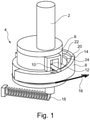
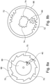
- figure 1 shows the schematic three-dimensional view of part of a prosthetic hand according to a first embodiment of the present invention.
- a portion of a thumb member 2 is mounted on a rotatable frame 4 having a rotating plate 6 which can rotate relative to a profiled wheel 8 which is stationary.
- a guide pin 10 is arranged to the side of the rotary plate 6 and is pressed radially outwards and downwards by at least one spring 12 . It slides along a guide contour 14 on the profile disk 8 .
- the control force can be exerted along the arrow 16 . This is exerted on the frame 4 and thus on the rotary plate 6, the guide pin 10 and the thumb element 2, but not on the profile disk 8.
- a restoring force exercised For a Kraftaufbringelement 18, which is designed as a coil spring in the embodiment shown, a restoring force exercised.
- the direction of the control force and thus the direction of the arrow 16 can change in the course of the movement. This is preferably achieved by a flexible, non-elastic connection, which acts on the circumference of the rotary plate 6 at the same point at which the guide pin 10 is also located.
- a control force is now exerted along the arrow 16 which is less than a predetermined limit value, the rotary plate 6 and the thumb element 7 are rotated relative to the profile disk 8 and the guide pin 10 slides off the guide contour 14 .
- the at least one spring 12 is tensioned in the vertical direction.
- the guide contour 14 has a maximum point 20 that cannot be reached by a control force that is smaller than the first predetermined limit value. If the control force 16 is reduced or omitted completely, the restoring force applied by the force application element 18 ensures that the thumb element 2 with the frame 4 is rotated back into the starting position. However, if the control force is chosen to be greater than the predetermined limit, the guide pin 10 will reach the maximum point 20.
- the radially outer guide contour 14 is formed in the radial direction in the rear region (not shown) in such a way that the guide pin 10 is pressed into the rotary plate 6 counter to the spring force applied by the spring 12 .
- the guide pin 10 slides on the radially inner guide contour 22, with the spring 12 being tensioned again in the vertical direction.
- the guide contour 22 also has a maximum point 24 over which the guide pin 10 slides supported by the spring force of the spring 12 acting in the vertical direction when a control force is applied that is greater than the second predetermined limit.
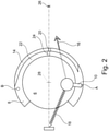
- figure 2 shows the representation schematically from above. You can see the thumb element 2, the rotary plate 6 as well as the force application element 18 and the profile disk 8. It has the radially outer guide contour 14 and the radially inner guide contour 22. Both each have a maximum point 20, 24.
- the guide pin 10 is located in the figure shown Embodiment at a first end point of the movement contour.
- the rotary plate 6 is rotated about the axis of rotation 28 by the control force to be applied along the arrow 16 and the guide pin 10 slides on the outer guide contour 14 .
- the control force is greater than the first predetermined limit value, the maximum point 24 of the outer guide contour 14 is reached and the spring force applied by the spring 12 and the restoring force applied by the force application element 18 ensure that the guide pin 10 moves to the opposite, second end point slides on. It can be seen that the outer guide contour 14 tapers radially outwards in this area. If a control force is applied again, the guide pin 10 slides along the radially inner guide contour 22 and the hand opens and closes in the second mode as long as the second predetermined limit value is not exceeded.
- the direction of the control force can change during the course of the movement, but preferably always passes through the point 26.
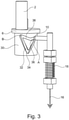
- figure 3 shows an alternative embodiment.
- the thumb element 2 is arranged on a rotating plate 6 .
- a cylinder 30 in which a heart-shaped groove 32 is located.
- the control force can be applied along arrow 16 again.
- the guide pin 10 is moved downwards in the groove 32 from the rest position A, while rotating the rotary plate 6 counterclockwise. If the control force 16 is less than the first predetermined limit value, when the Control force of the guide pin 10 by the force application element 18 back into the in figure 3 position A shown and thus remains in the same gripping mode.
- the guide pin 10 is pulled into the minimum point 34 and, when the control force is reduced, will move along a left portion of the groove 32, with the rotary plate 6 continuing to rotate counterclockwise until the second end point B is reached is, which corresponds to a second gripping mode.
- the guide pin 16 will move along the upper left arc 36 of the heart-shaped groove 32 upon the occurrence of a control force along the arrow 16, with the rotary plate 6 being rotated clockwise. If the force is reduced again before the minimum point 36 is reached, the hand remains in the second gripping mode and reaches the rest position in point B, controlled by the restoring force of the force application element 18 . It is only when the minimum point 36 (upper minimum) is reached that the first mode is switched back in that the rotary plate 6 is rotated further clockwise and the end position A is reached.
- Figure 4a shows a further embodiment of a part of the hand prosthesis.
- the thumb element 2 is arranged on a lever 40 which is pivotably mounted about a pivot axis 38 and at the end of which opposite the thumb element 2 the force-applying element 18 is arranged in the form of a tension spring.
- the lever 40 has a cam 42 which slides on an outer contour 44 of a cam 46 .
- the cam disk 46 is connected to a ratchet element 48 in a rotationally fixed manner. Both elements together can be rotated about the axis of rotation 28 .
- a lever 50 is present, on which the control force is exerted along arrow 16 .
- control force applied along the arrow 16 is greater than a predetermined limit value, the maximum point 20 is exceeded, so that the lever 40 no longer moves into the in figure 4 position shown. Instead, the force applying element 18 pulls the cam 42 to the second end position B, which corresponds to a different gripping mode.
- Figure 4b shows a similar configuration Figure 4a .
- the difference between the two figures is the outer contour 44 of the cam disk 46 and the position of the axis of rotation 28. While the axis of rotation 28 in Figure 4a is arranged in such a way that in each case two of the possible settings, namely the opposite sides of the cam disc 46, are of identical design and so two setting options are available for two modes, the axis of rotation 28 is in Figure 4b not located in the center of the cam 46. If a control force is applied by the lever 50 along the direction of the arrow 16 which is greater than the predetermined limit value, the ratchet element 48 is further rotated by 90°. This means that another side of the outer contour 44 of the cam disk 46 comes into contact with the cam 42 . Since the different sides of the outer contour 44 are at different distances from the axis of rotation 28, four different operating modes of the thumb element are achieved in this way.
- the thumb element 2 can be displaced in a groove 32 by means of a control force 16 against the force of a force-applying element 18 .
- the groove has two branches 54, at the ends of which the first end point A and the second end point B are located. Between the two branches 54 there is a switchover element 56 which is rotatably mounted about the axis of rotation 28 .
- Figure 6a shows the situation of the two branches 54 of the groove 32 with the switching element 56 in FIG figure 5 shown position. If a control force is applied to the thumb element 2, it reaches the in Figure 6b position shown. The switching element 56 has two indentations 58, with the thumb element 2, pulled by the control force 16, being introduced into one of these two indentations. By further increasing the control power, the in Figure 6c position shown. The thumb element 2 has exceeded the maximum point 20 of the groove and thereby rotated the switching element 56 about the axis of rotation 28 . A further increase leads to the in Figure 6d shown situation.
- the switching element 56 was rotated further about the axis of rotation 28 until a spring-loaded plunger 60, which is slidably mounted on the switching element 56, also exceeds its maximum point 24. Due to the force exerted by the spring element of the spring-loaded plunger 60 on the switching element 56, the switching element 56 is rotated further about the axis of rotation until it reaches the in Figure 6e has reached the second end position shown. The thumb element 2 has left the area shown in the lower branch 54 of the groove 32 and has thus reached the end position B.
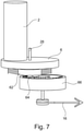
- FIG. 7 Another embodiment is figure 7 refer to.
- the thumb element 2 is again arranged on the rotary plate 6 which is mounted so as to be rotatable about an axis of rotation 28 . It is connected via a transmission disk 62 to which the rotary plate 6 is coupled in a rotationally fixed manner to a gear wheel 64 which rotates in a drive disk 66 .
- the control force can be applied to the mechanism along the arrow 16 .
- Figure 8a shows the underside of the drive pulley 66.
- the control force is applied via a contoured pulley 68.
- the lever 40 interacts with the teeth 70 in the manner of a freewheel. If the contour disk 68 is moved clockwise by the control force, this causes the drive disk 66 to rotate the contour disk 68 can be rotated counterclockwise while the drive disk 66 remains in position.
- Figure 8b 12 shows a top view of the drive pulley 66. It can be seen that it has two outer toothed areas 72 and two inner toothed areas 74.
- the gear 64 engages the external tooth portion 72 or the internal tooth portion 74 depending on the mode in which the thumb member is operated and is rotated clockwise or counterclockwise by rotation of the drive pulley 66 depending on the tooth portion engaged, achieving different modes.
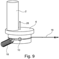
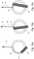
- FIG. 9 , 10a, 10b, 10c and 11 show a further embodiment in which the thumb element 2 is rotatably mounted on a rotary plate 6 about the axis of rotation 28 .
- the restoring force applied by the force application element 18 acts on the guide pin 10 to which the control force can also be applied along the arrow 16 .
- Figure 10a and 10b show the schematic situation from below.
- the guide pin 10 is contained in a recess, not shown, in the rotating plate 6 .
- the restoring force applied by the force application element 18 acts on the guide pin 10.
- the control force is applied via a traction cable 76 along the arrow 16.
- the in does not occur Figure 10b shown maximum rotation, but the guide pin 10 is a maximum of up to a position between in the Figures 10a and 10b rotated position shown.
- the restoring force 18 causes the in Figure 10a shown first end position reached.
- the in Figure 10b shown maximum displacement position of the guide pin 10 is reached. In this case, the pull cable 76 and the arrow 16 extend parallel to the longitudinal direction of the guide pin 10, which is thus pulled out of the recess at least a little.
- Figure 10c Figure 1 shows the situation where the control force applied along the direction of arrow 16 has exceeded the predetermined first limit value. Man recognizes that the restoring force 18 will now pull the guide pin 10 into the right part of the circular guide, so that the thumb element is operated in the second mode.
- figure 11 shows an enlarged sectional view through the rotary plate 6, in which the recess 78 is located, in which the guide pin 10 is arranged.
- the guide pin 10 is pulled into the recess 78 by the spring element 80 .
- a heart-shaped groove 32 can be seen on the guide pin, which in the shape and design of the figure 3 showed groove corresponds.
- the schematically indicated control pin 82 which is positioned in the heart-shaped groove 32 , is stationary on the portion of the rotary plate 6 that is not shown due to the sectional view. He is in figure 11 in the first end point A, so that the point of application of the restoring force, which is applied by the force application element 18, is to the left of the axis of rotation 28 of the rotary plate 6 in this view. Is now the in Figure 10b When the maximum rotational position shown is reached and the guide pin is pulled radially outwards from the recess 78, it rotates in the groove 32 as a result of the displacement of the control pin 82.
- control pin 82 When the control force decreases before the maximum point 20 is reached, the control pin 82 is pulled back into position A by the spring 80 .
- a control force 16 that reaches or exceeds a predetermined limit value pulls the guide pin 10 so far and rotates it accordingly that the control pin 82 reaches the maximum point 20 . If the control force 16 is then reduced, the spring 80 pulls the guide pin 82 back into the recess 78, with the control pin 82 running through the path shown on the right until it reaches the end position B.
- the guide pin 82 has been rotated so far that the point of application of the restoring force, which is applied by the force application element 18, is now to the right of the axis of rotation 28 of the rotary plate 6 and the rotary plate 6 is rotated accordingly in the other direction, resulting in an alternative thumb position will.
- FIGs 12, 13 and 14 show different states of a prosthetic hand in three representations arranged next to each other.
- the hand In the illustration on the left, the hand is shown in the so-called opposition grip, in which the tip of the thumb rests on the tip of the index finger.
- the thumb element 2 is shown schematically in the hand.
- no control force is exerted, so that the hand is closed.
- a control force 16 is exerted on the thumb element 2, so that the hand is opened.
- the control force in this case is smaller than the predetermined limit value, there is no mode change. If the control force 16 is reduced or completely removed, the in figure 12 Enter the situation shown at right with the hand still in the opposition grip.
- figure 13 also shows in the illustration on the left a hand with a thumb element 2 on which no control force 16 is exerted. Unlike in figure 12 is the hand in figure 13 but in the so-called lateral grip, so that the thumb rests on the side surface of the index finger. In the middle depiction of figure 13 a control force 16 is exerted on the thumb element 2 so that the hand is opened. In this case too, however, the control force 16 is smaller than the predetermined limit value, so that when the control force 16 is reduced and removed, the hand closes again and the figure 13 situation shown on the right. The hand is closed and still in the lateral grip.
- figure 14 shows in her left depiction a closed hand in the opposition grip.
- a control force is not exerted on the thumb element 2 .
- the hand is opened by the control force 16.
- the tax power exceeds the predetermined limit value in this case, so that there is a mode change of the hand. If the control force 16 is reduced again or completely removed, the in figure 14 situation shown on the right, in which the hand is closed but no longer in the opposition grip but in the lateral grip. A mode change has occurred.
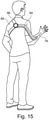
- FIG 15 shows a wearer of a prosthetic hand according to an embodiment of the present invention.
- a traction force which acts as a control force 16 can be exerted via a traction cable 76.
- a pull strap 84 On the pull cable 76 is a pull strap 84 which is arranged via a shoulder loop 86 on a shoulder 88 of the wearer. In this way, the wearer can apply the necessary tensile force by moving the shoulder 88 .
Landscapes
- Health & Medical Sciences (AREA)
- Transplantation (AREA)
- Biomedical Technology (AREA)
- Cardiology (AREA)
- Oral & Maxillofacial Surgery (AREA)
- Engineering & Computer Science (AREA)
- Orthopedic Medicine & Surgery (AREA)
- Heart & Thoracic Surgery (AREA)
- Vascular Medicine (AREA)
- Life Sciences & Earth Sciences (AREA)
- Animal Behavior & Ethology (AREA)
- General Health & Medical Sciences (AREA)
- Public Health (AREA)
- Veterinary Medicine (AREA)
- Prostheses (AREA)
Description
Die Erfindung betrifft eine Prothesenhand mit einem Daumenelement und wenigstens einem Fingerelement, wobei das Daumenelement durch eine Steuerkraft relativ zu dem wenigstens einen Fingerelement bewegbar ausgebildet ist.The invention relates to a prosthetic hand with a thumb element and at least one finger element, the thumb element being designed to be movable relative to the at least one finger element by a control force.
Derartige Prothesenhände sind aus dem Stand der Technik seit langem bekannt. Aus den
Handprothesen können motorbetrieben sein, wobei insbesondere unterschiedliche Fingerelemente und das Daumenelement separat angetrieben und bewegt werden können. Derartige Handprothesen sind schwer, aufwendig und kostenintensiv. In alternativen Ausgestaltungen der Handprothesen, die nicht motorbetrieben sein müssen, wird die Steuerkraft durch ein Zugkraftelement ausgeübt, das beispielweise entlang des Armes des Trägers über die Schulter oder den Rumpf geführt wird. Durch eine Bewegung der Schulter auf der gegenüberliegenden Seite der durch die Prothesenhand versorgten oberen Gliedmaße wird die Steuerkraft aufgebracht und die Hand geöffnet oder geschlossen.Hand prostheses can be motor-driven, in which case, in particular, different finger elements and the thumb element can be driven and moved separately. Such hand prostheses are heavy, complicated and expensive. In alternative embodiments of the prosthetic hands that do not have to be motorized, the control force is applied by a traction element passed, for example, along the wearer's arm over the shoulder or trunk. Movement of the shoulder on the opposite side of the upper limb being served by the prosthetic hand applies the control force and opens or closes the hand.
Mit einer Prothesenhand der eingangs erwähnten Art kann folglich ein Gegenstand gegriffen werden. Dabei wird häufig der sogenannte Oppositionsgriff verwendet, bei dem der Gegenstand zwischen der Fingerspitze des wenigstens einen Fingerelementes und der Spitze des Daumenelementes gegriffen wird. Dies ist jedoch für eine Vielzahl von Handhabungen unterschiedlicher Gegenstände, beispielsweise eines Schlüssels, unpraktisch. Mit einer gesunden natürlichen Hand würde der Griff gewechselt und der sogenannte Lateralgriff verwendet werden. Dabei wird der zu greifende Gegenstand zwischen dem Daumen und der Seitenkante des Zeigefingers eingeklemmt. Es gibt zwar motorbetriebene Prothesenhände, bei denen über Steuersignale von einem in den anderen Griffmodus umgeschaltet werden kann, für nichtmotorbetriebene Prothesenhände sind Umschaltungen der Daumenposition aus dem Stand der Technik nicht bekannt. Eine solche Prothesenhand ist aus der
Die Erfindung löst die gestellte Aufgabe durch eine Prothesenhand mit einem Daumenelement und wenigstens einem Fingerelement, wobei das Daumenelement durch eine Steuerkraft relativ zu dem wenigstens einen Fingerelement bewegbar ausgebildet ist, wobei sich die Prothesenhand dadurch auszeichnet, dass das Daumenelement in wenigstens einem ersten Modus entlang einer ersten Trajektorie und in wenigstens einem zweiten Modus entlang einer zweiten Trajektorie relativ zu dem wenigstens einen Fingerelement bewegbar ist und von dem ersten Modus in den zweiten Modus bringbar ist, indem die Steuerkraft einen ersten vorbestimmten Grenzwert übersteigt. Vorzugsweise kann das Daumenelement in mehr als zwei Modi, insbesondere drei oder vier Modi bewegt werden. Dabei wird das Daumenelement von einem Modus in einen anderen Modus gebracht, indem die Steuerkraft einen vor diesen Moduswechsel vorbestimmten Grenzwert überschreitet. Dieser Grenzwert kann für alle Moduswechsel gleich oder individuell verschieden gewählt sein.The invention solves the problem set by a prosthetic hand with a thumb element and at least one finger element, the thumb element being designed to be movable relative to the at least one finger element by a control force, the prosthetic hand being characterized in that the thumb element can be moved in at least a first mode along a first trajectory and in at least one second mode along a second trajectory relative to the at least one finger element and is movable from the first mode to the second mode by the control force exceeding a first predetermined limit value. The thumb element can preferably be moved in more than two modes, in particular three or four modes. In this case, the thumb element is brought from one mode to another mode in that the control force exceeds a limit value predetermined before this mode change. This limit value can be selected to be the same for all mode changes or to be individually different.
Vorteilhafterweise ist das Daumenelement von dem zweiten Modus in den ersten Modus bringbar, indem die Steuerkraft einen zweiten vorbestimmten Grenzwert überschreitet. Dabei hat es sich als vorteilhaft herausgestellt, wenn der erste vorbestimmte Grenzwert identisch zum zweiten vorbestimmten Grenzwert ist.Advantageously, the thumb element can be brought from the second mode into the first mode by the control force exceeding a second predetermined limit value. It has turned out to be advantageous if the first predetermined limit value is identical to the second predetermined limit value.
Mit einer Handprothese kann der Träger folglich einfach zwischen den beiden Greifmodi umschalten, indem die ohnehin aufzubringende Steuerkraft vergrößert wird. Vorteilhafterweise verfügt die Prothesenhand über eine mechanische Anordnung, die in einen Totpunkt oder über einen Totpunkt hinweg bewegt wird, indem die Steuerkraft den vorbestimmten Grenzwert übersteigt.With a hand prosthesis, the wearer can therefore easily switch between the two gripping modes by increasing the control force that has to be applied anyway. Advantageously, the prosthetic hand has a mechanical arrangement that is moved to a dead center or beyond a dead center by the control force exceeding the predetermined limit value.
Vorteilhafterweise verfügt die Prothesenhand über wenigstens ein Kraftaufbringelement, das eine Rückstellkraft auf das Daumenelement und vorzugsweise auf das wenigstens eine Fingerelement aufbringt, die der Steuerkraft entgegengerichtet ist. Ein solches Kraftaufbringelement kann ein Federelement, beispielsweise eine Torsionsfeder, eine Konstantkraftfeder oder eine Schraubenfeder sein. Dadurch wird sichergestellt, dass die Stellung der Prothesenhand ohne durch den Träger aufgebrachte Steuerkraft der geschlossene Zustand ist. Je nach Modus, in dem sich das Daumenelement befindet, ist diese Endstellung bevorzugt entweder der Oppositionsgriff oder der Lateralgriff.Advantageously, the prosthetic hand has at least one force application element that applies a restoring force to the thumb element and preferably to the at least one finger element, which is directed in the opposite direction to the control force. Such a force application element can be a spring element, for example a torsion spring, a constant force spring or a helical spring. This ensures that the position of the prosthetic hand is the closed state with no control force applied by the wearer. Depending on the mode in which the thumb element is located, this end position is preferably either the opposition grip or the lateral grip.
Die Rückstellkraft ist bevorzugt derart gewählt, dass sie das Daumenelement ohne Steuerkraft im ersten Modus in eine erste Endposition und im zweiten Modus in eine zweite Endposition bringt, die von der ersten Endposition verschieden ist. Dabei handelt es sich bevorzugt um die bereits genannten Griffmodi "Oppositionsgriff" und "Lateralgriff". In diesen Fällen liegt das Daumenelement in der ersten Endposition und/oder in der zweiten Endposition an dem wenigstens einen Fingerelement an. Dabei ist zu beachten, dass das Daumenelement in den unterschiedlichen Endpositionen an unterschiedlichen Teilen des Fingerelementes, beispielsweise einer Fingerkuppe oder einer Seitenfläche des Fingerelementes, anliegt.The restoring force is preferably selected in such a way that it brings the thumb element into a first end position in the first mode and into a second end position in the second mode, which is different from the first end position, without a control force. These are preferably the gripping modes “opposition grip” and “lateral grip” already mentioned. In these cases, the thumb element rests against the at least one finger element in the first end position and/or in the second end position. It should be noted that in the different end positions the thumb element is in contact with different parts of the finger element, for example a fingertip or a side surface of the finger element.
Vorteilhafterweise verfügt die Prothesenhand über wenigstens ein Zugelement, durch das die Steuerkraft aufbringbar ist. Dieses Zugelement ist vorteilhafterweise an der Schulter, vorzugsweise an der der Prothesenhand gegenüberliegenden Schulter, oder einem Rumpf des Trägers der Prothesenhand angeordnet.Advantageously, the prosthetic hand has at least one traction element through which the control force can be applied. This pulling element is advantageously arranged on the shoulder, preferably on the shoulder opposite the prosthetic hand, or on a torso of the wearer of the prosthetic hand.
Das Daumenelement wird im ersten Modus entlang einer ersten Trajektorie bewegt, wenn eine Steuerkraft aufgebracht wird. Solange die Steuerkraft den vorbestimmten ersten Grenzwert nicht überschreitet, verbleibt das Daumenelement im ersten Modus und die Hand wird durch die Steuerkraft geöffnet und durch Nachlassen oder Entfallen der Steuerkraft entlang der ersten Trajektorie geschlossen. Überschreitet sie jedoch den ersten vorbestimmten Grenzwert, wird das Daumenelement oder ein mit ihm verbundenes Element vorzugsweise über einen Totpunkt der Bewegung hinweg bewegt und folgt nun der zweiten Trajektorie, sobald die Steuerkraft nachlässt. Wird die Steuerkraft wieder erhöht, ohne den zweiten vorbestimmten Grenzwert zu überschreiten, wird die Hand erneut geöffnet und beim Nachlassen oder Wegfallen der Steuerkraft wieder entlang der zweiten Trajektorie geschlossen. Dadurch wird die Hand in dem zweiten Modus, beispielsweise ein anderer Griffmodus, verwendet. Wird die Steuerkraft über den zweiten vorbestimmten Grenzwert erhöht, wird das Daumenelement oder ein mit ihm verbundenes Element erneut über den Totpunkt der Bewegung hinweg bewegt, der der gleiche oder ein anderer Totpunkt sein kann. Wird die Steuerkraft anschließend reduziert oder entfällt vollständig, wird die Hand erneut geschlossen und das Daumenelement bewegt sich erneut entlang der ersten Trajektorie im ersten Modus.In the first mode, the thumb member is moved along a first trajectory when a control force is applied. As long as the control force does not exceed the predetermined first limit value, the thumb element remains in the first mode and the hand is opened by the control force and closed by reducing or eliminating the control force along the first trajectory. However, if it exceeds the first predetermined limit value, the thumb element or an element connected to it is preferably moved past a dead center of the movement and now follows the second trajectory as soon as the control force decreases. If the control force is increased again without exceeding the second predetermined limit value, the hand is opened again and closed again along the second trajectory when the control force decreases or disappears. As a result, the hand is used in the second mode, for example a different gripping mode. If the control force is increased above the second predetermined limit, the thumb element or an element connected to it is again moved over the dead center of the movement, which may be the same or a different dead center. If the control force is subsequently reduced or eliminated completely, the hand is closed again and the thumb element again moves along the first trajectory in the first mode.
Vorzugsweise ist das Daumenelement in wenigstens einem dritten Modus entlang einer dritten Trajektorie und vorzugsweise in wenigstens einem vierten Modus entlang einer vierten Trajektorie bewegbar.Preferably, the thumb element is movable in at least a third mode along a third trajectory and preferably in at least a fourth mode along a fourth trajectory.
Das Zugelement ist in einer besonderen Ausführungsform durch einen Aktuator betätigbar. Dies kann beispielsweise ein motorgetriebener Aktuator sein, der ein Betätigungselement aufweist.In a special embodiment, the pull element can be actuated by an actuator. This can be a motor-driven actuator, for example, which has an actuating element.
Alternativ zu dem Umschalten zwischen unterschiedlichen Bewegungsmodi dadurch, dass eine Steuerkraft einen vorbestimmten Grenzwert übersteigt, kann auch eine Fliehkraftkupplung oder eine ähnliche Ausgestaltung vorgesehen sein, bei der das Umschalten zwischen mehreren Bewegungsmodi dann geschieht, wenn eine Bewegung eines Aktuators, beispielsweise eines Zugseils, eine Geschwindigkeit aufweist, die einen vorbestimmten Grenzwert überschreitet. Die verschiedenen Ausgestaltungen können mutatis mutandis angewandt werden. Auch hier ist es möglich, mehr als zwei Bewegungsmodi vorzusehen. Das Umschalten zwischen unterschiedlichen Bewegungsmodi erfordert das Überschreiten vorbestimmter Grenzwerte, die je nach Modus, in dem geschaltet werden soll, unterschiedlich oder identisch ausgebildet werden können.As an alternative to switching between different movement modes because a control force exceeds a predetermined limit value, a centrifugal clutch or a similar configuration can also be provided, in which switching between several movement modes takes place when a movement of an actuator, for example a traction cable, exceeds a speed has, which exceeds a predetermined limit value. The various configurations can be applied mutatis mutandis. Here, too, it is possible to provide more than two movement modes. Switching between different movement modes requires that predetermined limit values are exceeded, which can be designed to be different or identical depending on the mode in which switching is to take place.
Anhand der beiliegenden Zeichnungen werden nachfolgend einige Ausführungsbeispiele der vorliegenden Erfindung näher erläutert. Es zeigt:
- Figur 1 -
- die schematische dreidimensionale Ansicht eines Teils einer Prothesenhand,
- Figur 2 -
- die Darstellung aus
Figur 1 in einer Draufsicht, - Figur 3 -
- die schematische Ansicht eines Teils einer Prothesen-hand gemäß einem weiteren Ausführungsbeispiel der vorliegenden Erfindung,
- Figuren 4a und 4b -
- weitere schematische Ansichten eines Teils einer Pro-thesenhand,
- Figur 5 -
- die schematische Darstellung eines Teils eines weite-ren Ausführungsbeispiels der vorliegenden Erfindung,
- Figuren 6a bis 6e -
- verschiedene Stadien beim Umschalten der Vorrichtung aus
Figur 5 , - Figur 7 -
- die schematische Darstellung eines Teils einer weiteren Ausführungsform der vorliegenden Erfindung,
- Figur 8a und 8b -
- schematische Teilansichten der Vorrichtung aus
Figur 7 , - Figur 9 -
- die schematische Darstellung eines Teils einer weiteren Ausführungsform,
- Figur 10a bis 10c -
- schematische Teilansichten der
Figur 9 , - Figur 11 -
- eine schematische Schnittdarstellung durch ein Teil der Vorrichtung aus
Figur 9 , Figuren 12, 13 und 14 -- schematische Darstellungen unterschiedlicher Bewegungszustände und
- Figur 15 -
- die schematische Darstellung einer Handprothese im getragenen Zustand.
- Figure 1 -
- the schematic three-dimensional view of part of a prosthetic hand,
- Figure 2 -
- the representation
figure 1 in a top view, - Figure 3 -
- the schematic view of part of a prosthetic hand according to a further embodiment of the present invention,
- Figures 4a and 4b -
- further schematic views of a part of a prosthetic hand,
- Figure 5 -
- the schematic representation of a part of a further exemplary embodiment of the present invention,
- Figures 6a to 6e -
- different stages when switching the device
figure 5 , - Figure 7 -
- the schematic representation of part of a further embodiment of the present invention,
- Figure 8a and 8b -
- schematic partial views of the device
figure 7 , - Figure 9 -
- the schematic representation of part of a further embodiment,
- Figure 10a to 10c -
- schematic partial views of
figure 9 , - Figure 11 -
- a schematic sectional view through part of the device
figure 9 , - Figures 12, 13 and 14 -
- schematic representations of different states of motion and
- Figure 15 -
- the schematic representation of a hand prosthesis in worn condition.
Wird nun entlang des Pfeils 16 eine Steuerkraft ausgeübt, die kleiner ist als ein vorbestimmter Grenzwert, wird die Drehplatte 6 und das Daumenelement 7 relativ zur Profilscheibe 8 gedreht und der Führungspin 10 gleitet auf der Führungskontur 14 ab. Dabei wird die wenigstens eine Feder 12 in vertikaler Richtung gespannt Die Führungskontur 14 verfügt über einen Maximalpunkt 20, der durch eine Steuerkraft, die kleiner ist als der erste vorbestimmte Grenzwert, nicht erreicht wird. Wird die Steuerkraft 16 reduziert oder vollständig weggelassen, sorgt die durch das Kraftaufbringelement 18 aufgebrachte Rückstellkraft dafür, das Daumenelement 2 mit dem Gestell 4 wieder in die Ausgangsposition zurückzudrehen. Wird jedoch die Steuerkraft so gewählt, dass sie größer ist als der vorbestimmte Grenzwert, wird der Führungspin 10 den Maximalpunkt 20 erreichen. Durch die vertikal wirkende Federkraft auf den Führungspin 10 gleitet dieser der Schräge um den Maximalpunkt 20, der ein Totpunkt ist, ab und überschreitet damit diesen Totpunkt. Die durch das Kraftaufbringelement 18 aufgebrachte Rückstellkraft sorgt dafür, dass eine weitere Drehbewegung entgegen dem Uhrzeigersinn stattfindet, die das Gestell 4 mit dem Daumenelement 2 in die andere Endposition bringt.If a control force is now exerted along the
Wird erneut eine Steuerkraft entlang der Pfeilrichtung 16 aufgebracht, kommt es zu einer Drehung des Daumenelementes 2 und des Gestells 4 im Uhrzeigersinn. Die radial äußere Führungskontur 14 ist im nicht dargestellten hinteren Bereich in radialer Richtung derart ausgebildet, dass der Führungspin 10 entgegen der durch die Feder 12 aufgebrachte Federkraft in die Drehplatte 6 gedrückt wird. Dadurch gleitetder Führungspin 10 auf der radial inneren Führungskontur 22 ab, wobei die Feder 12 wieder in vertikaler Richtung gespannt wird. Auch die Führungskontur 22 verfügt über einen Maximalpunkt 24, über den der Führungspin 10 unterstützt von der in vertikaler Richtung wirkenden Federkraft der Feder 12 hinweggleitet, wenn eine Steuerkraft aufgebracht wird, die größer ist als der zweite vorbestimmte Grenzwert.If a control force is again applied in the direction of the
Die Richtung der Steuerkraft, die durch den Pfeil 16 visualisiert wird, kann sich im Verlauf der Bewegung ändern, durchläuft bevorzugt jedoch immer den Punkt 26.The direction of the control force, visualized by the
Die Steuerkraft kann wieder entlang des Pfeils 16 aufgebracht werden. Dadurch wird der Führungspin 10 in der Nut 32 aus der Ruheposition A nach unten verschoben wobei er die Drehplatte 6 gegen den Uhrzeigersinn rotiert. Ist die Steuerkraft 16 kleiner als der erste vorbestimmte Grenzwert, wird beim Nachlassen der Steuerkraft der Führungspin 10 durch das Kraftaufbringelement 18 wieder in die in
Ist die Steuerkraft größer als der vorbestimmte Grenzwert, wird der Führungspin 10 in den Minimalpunkt 34 gezogen und wird sich beim Reduzieren der Steuerkraft entlang eines linken Anteils der Nut 32 bewegen, wobei die Drehplatte 6 weiter gegen den Uhrzeigersinn rotiert wird bis der zweite Endpunkt B erreicht ist, der einem zweiten Griffmodus entspricht.If the control force is greater than the predetermined limit value, the
Aus dem zweiten Endpunkt B heraus wird sich der Führungspin 16 beim Auftreten einer Steuerkraft entlang des Pfeils 16 entlang des oberen linken Bogens 36 der herzförmigen Nut 32 bewegen, wobei die Drehplatte 6 im Uhrzeigersinn gedreht wird. Wird die Kraft vor dem Erreichen des Minimalpunktes 36 wieder reduziert, verbleibt die Hand im zweiten Griffmodus und erreicht gesteuert durch die Rückstellkraft des Kraftaufbringelementes 18 in Punkt B die Ruheposition. Erst bei Erreichen des Minimalpunkts 36 (oberes Minimum) wird in den ersten Modus zurückgeschaltet, indem die Drehplatte 6 weiter im Uhrzeigersinn gedreht und die Endposition A erreicht wird.From the second end point B, the
Ist die entlang des Pfeils 16 aufgebrachte Steuerkraft größer als ein vorbestimmter Grenzwert, wird dabei der Maximalpunkt 20 überschritten, so dass sich der Hebel 40 bei Entlastung nicht mehr in die in
Bei der in
In den
Ein weiteres Ausführungsbeispiel ist
Die
Beim Nachlassen der Steuerkraft vor Erreichen des Maximalpunktes 20 wird der Steuerpin 82 durch die Feder 80 zurück in die Position A gezogen. Durch eine Steuerkraft 16, die einen vorbestimmten Grenzwert erreicht oder überschreitet, wird der Führungspin 10 so weit gezogen und entsprechend rotiert, dass der Steuerpin 82 den Maximalpunkt 20 erreicht. Wird dann die Steuerkraft 16 reduziert, zieht die Feder 80 den Führungspin 82 zurück in die Ausnehmung 78, wobei der Steuerpin 82 die rechte dargestellte Bahn durchläuft, bis er die Endposition B erreicht. Der Führungspin 82 ist dabei so weit rotiert worden, dass der Angriffspunkt der Rückstellkraft, die durch das Kraftaufbringelement 18 aufgebracht wird, nun rechts der Rotationsachse 28 der Drehplatte 6 liegt und die Drehplatte 6 entsprechend in die andere Richtung gedreht wird, wodurch ein alternative Daumenposition erreicht wird.When the control force decreases before the
Die gezeigten Ausführungsbeispiele sind lediglich zur Illustration und nicht beschränkend auszulegen. Selbstverständlich sind unterschiedlichste Formen der gezeigten Nuten, Führungen oder Kulissen möglich, um den gewünschten Effekt zu erreichen.The embodiments shown are for illustration only and are not to be construed as limiting. Of course, the grooves, guides or links shown can have a wide variety of shapes in order to achieve the desired effect.
Die
- AA
- erster Endpunktfirst endpoint
- BB
- zweiter Endpunktsecond end point
- 22
- Daumenelementthumb element
- 44
- Gestellframe
- 66
- Drehplatteturntable
- 88th
- Profilscheibeprofile washer
- 1010
- Führungspinguide pin
- 1212
- Federfeather
- 1414
- Führungskonturguide contour
- 1616
- Pfeil (Steuerkraft)arrow (steering force)
- 1818
- Kraftaufbringelementforce applying element
- 2020
- Maximalpunktmaximum point
- 2222
- innere Führungskonturinner guiding contour
- 2424
- Maximalpunktmaximum point
- 2626
- PunktPoint
- 2828
- Rotationsachseaxis of rotation
- 3030
- Zylindercylinder
- 3232
- Nutgroove
- 3434
- Minimalpunktminimum point
- 3636
- oberer Bogenupper arch
- 3838
- Schwenkachsepivot axis
- 4040
- Hebellever
- 4242
- Nockencam
- 4444
- Außenkonturouter contour
- 4646
- Kurvenscheibecam disk
- 4848
- Ratschenelementratchet element
- 5050
- Hebellever
- 5252
- Vorsprunghead Start
- 5454
- Astbranch
- 5656
- Umschaltelementswitching element
- 5858
- Vertiefungdeepening
- 6060
- Stößelpestle
- 6262
- Übertragungsscheibetransmission disk
- 6464
- Zahnradgear
- 6666
- Antriebsscheibedrive pulley
- 6868
- Konturscheibecontour disc
- 7070
- Zahntooth
- 7272
- äußerer Zahnbereichouter tooth area
- 7474
- innerer Zahnbereichinner tooth area
- 7676
- Zugseilpull rope
- 7878
- Ausnehmungrecess
- 8080
- Federelementspring element
- 8282
- Steuerpincontrol pin
- 8484
- Zuggurtdrawstring
- 8686
- Schulterschlaufeshoulder strap
- 8888
- Schultershoulder
Claims (9)
- A prosthetic hand withone thumb element (2) andat least one finger element,the thumb element (2) being designed such that it can be moved relative to the finger element by a steering force (16),
characterised in that
the thumb element (2) can be moved relative to the at least one finger element along a first trajectory in at least a first mode and along a second trajectory in at least a second mode, and can be brought from the first mode into the second mode by the steering force (16) exceeding a first predetermined limit. - The prosthetic hand according to claim 1, characterised in that the thumb element (2) can be brought from the second mode into the first mode by the steering force (16) exceeding a second predetermined limit, which is preferably identical to the first predetermined limit.
- The prosthetic hand according to claim 1 or 2, characterised in that the prosthetic hand has at least one force application element (18) that applies a restoring force to the thumb element (2) that opposes the steering force (16).
- The prosthetic hand according to claim 3, characterised in that the restoring force is selected in such a way that in the first mode it moves the thumb element (2) into a first end position (A) without the steering force (16) and in the second mode into a second end position (B) that differs from the first end position (A).
- The prosthetic hand according to claim 4, characterised in that in the first end position (A) and/or in the second position (B) the thumb element (2) rests on the at least one finger element.
- The prosthetic hand according to one of the preceding claims, characterised in that the prosthetic hand has at least one tension element (76) through which the steering force (16) can be applied.
- The prosthetic hand according to claim 6, characterised in that the at least one tension element (76) is designed to be arranged on a shoulder, preferably the opposite shoulder to the prosthetic hand, or a torso of a wearer of the prosthetic hand.
- The prosthetic hand according to claim 6 or 7, characterised in that the tension element (76) can be actuated by an actuator.
- The prosthetic hand according to one of the preceding claims, characterised in that the thumb element (2) can be moved in at least a third mode along a third trajectory and preferably in at least a fourth mode along a fourth trajectory.
Applications Claiming Priority (2)
| Application Number | Priority Date | Filing Date | Title |
|---|---|---|---|
| DE102017130082.1A DE102017130082B4 (en) | 2017-12-15 | 2017-12-15 | prosthetic hand |
| PCT/EP2018/084670 WO2019115665A1 (en) | 2017-12-15 | 2018-12-13 | Prosthetic hand |
Publications (2)
| Publication Number | Publication Date |
|---|---|
| EP3723669A1 EP3723669A1 (en) | 2020-10-21 |
| EP3723669B1 true EP3723669B1 (en) | 2022-03-23 |
Family
ID=65033553
Family Applications (1)
| Application Number | Title | Priority Date | Filing Date |
|---|---|---|---|
| EP18836353.5A Active EP3723669B1 (en) | 2017-12-15 | 2018-12-13 | Prosthetic hand |
Country Status (3)
| Country | Link |
|---|---|
| EP (1) | EP3723669B1 (en) |
| DE (1) | DE102017130082B4 (en) |
| WO (1) | WO2019115665A1 (en) |
Families Citing this family (1)
| Publication number | Priority date | Publication date | Assignee | Title |
|---|---|---|---|---|
| EP4378429A1 (en) | 2022-12-01 | 2024-06-05 | Oscar Feltrin | Multi-articulated powered hand prosthesis |
Citations (1)
| Publication number | Priority date | Publication date | Assignee | Title |
|---|---|---|---|---|
| EP0045818B1 (en) * | 1979-06-22 | 1985-05-22 | Grau, Hermann | Hand prosthesis |
Family Cites Families (7)
| Publication number | Priority date | Publication date | Assignee | Title |
|---|---|---|---|---|
| JP3086452B1 (en) | 1999-05-19 | 2000-09-11 | 原田電子工業株式会社 | Movable finger for artificial limb, artificial hand using the movable finger, and control device for the movable finger |
| DE102005061313A1 (en) * | 2005-12-20 | 2007-08-16 | Otto Bock Healthcare Ip Gmbh & Co. Kg | hand prosthesis |
| US9114030B2 (en) | 2007-02-06 | 2015-08-25 | Deka Products Limited Partnership | System for control of a prosthetic device |
| US9174339B2 (en) * | 2010-11-22 | 2015-11-03 | Vanderbilt University | Control system for a grasping device |
| ITPI20130004A1 (en) | 2013-01-16 | 2014-07-17 | Machinale S R L Fab | PROSTHETIC STRUCTURE FOR HAND AMPUTATION |
| DE102014001390A1 (en) * | 2014-02-05 | 2015-09-24 | Stefan Schulz | Method for controlling a prosthesis |
| DE202016003671U1 (en) * | 2016-06-13 | 2017-09-15 | Lüder Mosler | Handle style change for artificial hands |
-
2017
- 2017-12-15 DE DE102017130082.1A patent/DE102017130082B4/en not_active Expired - Fee Related
-
2018
- 2018-12-13 EP EP18836353.5A patent/EP3723669B1/en active Active
- 2018-12-13 WO PCT/EP2018/084670 patent/WO2019115665A1/en unknown
Patent Citations (1)
| Publication number | Priority date | Publication date | Assignee | Title |
|---|---|---|---|---|
| EP0045818B1 (en) * | 1979-06-22 | 1985-05-22 | Grau, Hermann | Hand prosthesis |
Also Published As
| Publication number | Publication date |
|---|---|
| EP3723669A1 (en) | 2020-10-21 |
| WO2019115665A1 (en) | 2019-06-20 |
| DE102017130082A1 (en) | 2019-06-19 |
| DE102017130082B4 (en) | 2019-07-04 |
Similar Documents
| Publication | Publication Date | Title |
|---|---|---|
| EP2874548B1 (en) | Endoscopic instrument | |
| DE1553692C3 (en) | Scissors or similar tool | |
| DE102007049032A1 (en) | Plier, has movable plier leg selectively fixable in relation to fixed plier leg, and joint pin released from interlock merely by tensile loading of movable plier leg transversely to longitudinal extension of longitudinal slot | |
| EP3740708B1 (en) | Valve actuating device | |
| DE10110106A1 (en) | Surgical forceps | |
| DE4303180C1 (en) | Manually operable shears for cutting cables, profiles, branches etc. - comprises two linked hand levers, of which one evolves into fixed cutting jaw | |
| DE2356853A1 (en) | SCISSORS-LIKE INSTRUMENT AND METHOD FOR MANUFACTURING IT | |
| EP1050378B1 (en) | Single-handed actuated pliers | |
| WO1993004606A1 (en) | Depilatory device | |
| EP3673725A1 (en) | Cutting device | |
| DE69400955T2 (en) | WIRE STRIPPER | |
| EP3723669B1 (en) | Prosthetic hand | |
| DE2416781B2 (en) | Wire stripper | |
| DE2512900C3 (en) | Selection for program switchgear | |
| DE2555071C2 (en) | Manually operated device for crimping cable lugs, cable connectors or the like. | |
| DE102011011511A1 (en) | Crimping tool with an actuated by a cam device crimping jaw | |
| DE102010007917B4 (en) | Hand-operated tool | |
| DE102008014946A1 (en) | A hair removal | |
| EP3078454B1 (en) | Device with parallel gripping surface | |
| EP3582665B1 (en) | Device for gripping an object | |
| DE2848445C2 (en) | Device for stripping electrical conductors | |
| DE19909224A1 (en) | Circlip pliers have movable part along curved slot with inner serrated catches as bearings for joint-pin | |
| DE4313996C1 (en) | Hand-operated tongs | |
| DE202010007994U1 (en) | Quick release with double cams | |
| DE630494C (en) | Safety razor |
Legal Events
| Date | Code | Title | Description |
|---|---|---|---|
| STAA | Information on the status of an ep patent application or granted ep patent |
Free format text: STATUS: UNKNOWN |
|
| STAA | Information on the status of an ep patent application or granted ep patent |
Free format text: STATUS: THE INTERNATIONAL PUBLICATION HAS BEEN MADE |
|
| PUAI | Public reference made under article 153(3) epc to a published international application that has entered the european phase |
Free format text: ORIGINAL CODE: 0009012 |
|
| STAA | Information on the status of an ep patent application or granted ep patent |
Free format text: STATUS: REQUEST FOR EXAMINATION WAS MADE |
|
| 17P | Request for examination filed |
Effective date: 20200609 |
|
| AK | Designated contracting states |
Kind code of ref document: A1 Designated state(s): AL AT BE BG CH CY CZ DE DK EE ES FI FR GB GR HR HU IE IS IT LI LT LU LV MC MK MT NL NO PL PT RO RS SE SI SK SM TR |
|
| AX | Request for extension of the european patent |
Extension state: BA ME |
|
| RIN1 | Information on inventor provided before grant (corrected) |
Inventor name: BIERBAUM, SARAH Inventor name: BRUENJES, LUKAS Inventor name: BERTELS, THOMAS |
|
| DAV | Request for validation of the european patent (deleted) | ||
| DAX | Request for extension of the european patent (deleted) | ||
| GRAP | Despatch of communication of intention to grant a patent |
Free format text: ORIGINAL CODE: EPIDOSNIGR1 |
|
| STAA | Information on the status of an ep patent application or granted ep patent |
Free format text: STATUS: GRANT OF PATENT IS INTENDED |
|
| INTG | Intention to grant announced |
Effective date: 20211007 |
|
| GRAS | Grant fee paid |
Free format text: ORIGINAL CODE: EPIDOSNIGR3 |
|
| GRAA | (expected) grant |
Free format text: ORIGINAL CODE: 0009210 |
|
| STAA | Information on the status of an ep patent application or granted ep patent |
Free format text: STATUS: THE PATENT HAS BEEN GRANTED |
|
| AK | Designated contracting states |
Kind code of ref document: B1 Designated state(s): AL AT BE BG CH CY CZ DE DK EE ES FI FR GB GR HR HU IE IS IT LI LT LU LV MC MK MT NL NO PL PT RO RS SE SI SK SM TR |
|
| REG | Reference to a national code |
Ref country code: GB Ref legal event code: FG4D Free format text: NOT ENGLISH |
|
| REG | Reference to a national code |
Ref country code: CH Ref legal event code: EP |
|
| REG | Reference to a national code |
Ref country code: DE Ref legal event code: R096 Ref document number: 502018009202 Country of ref document: DE |
|
| REG | Reference to a national code |
Ref country code: IE Ref legal event code: FG4D Free format text: LANGUAGE OF EP DOCUMENT: GERMAN |
|
| REG | Reference to a national code |
Ref country code: AT Ref legal event code: REF Ref document number: 1476940 Country of ref document: AT Kind code of ref document: T Effective date: 20220415 |
|
| REG | Reference to a national code |
Ref country code: LT Ref legal event code: MG9D |
|
| REG | Reference to a national code |
Ref country code: NL Ref legal event code: MP Effective date: 20220323 |
|
| PG25 | Lapsed in a contracting state [announced via postgrant information from national office to epo] |
Ref country code: SE Free format text: LAPSE BECAUSE OF FAILURE TO SUBMIT A TRANSLATION OF THE DESCRIPTION OR TO PAY THE FEE WITHIN THE PRESCRIBED TIME-LIMIT Effective date: 20220323 Ref country code: RS Free format text: LAPSE BECAUSE OF FAILURE TO SUBMIT A TRANSLATION OF THE DESCRIPTION OR TO PAY THE FEE WITHIN THE PRESCRIBED TIME-LIMIT Effective date: 20220323 Ref country code: NO Free format text: LAPSE BECAUSE OF FAILURE TO SUBMIT A TRANSLATION OF THE DESCRIPTION OR TO PAY THE FEE WITHIN THE PRESCRIBED TIME-LIMIT Effective date: 20220623 Ref country code: LT Free format text: LAPSE BECAUSE OF FAILURE TO SUBMIT A TRANSLATION OF THE DESCRIPTION OR TO PAY THE FEE WITHIN THE PRESCRIBED TIME-LIMIT Effective date: 20220323 Ref country code: HR Free format text: LAPSE BECAUSE OF FAILURE TO SUBMIT A TRANSLATION OF THE DESCRIPTION OR TO PAY THE FEE WITHIN THE PRESCRIBED TIME-LIMIT Effective date: 20220323 Ref country code: BG Free format text: LAPSE BECAUSE OF FAILURE TO SUBMIT A TRANSLATION OF THE DESCRIPTION OR TO PAY THE FEE WITHIN THE PRESCRIBED TIME-LIMIT Effective date: 20220623 |
|
| PG25 | Lapsed in a contracting state [announced via postgrant information from national office to epo] |
Ref country code: LV Free format text: LAPSE BECAUSE OF FAILURE TO SUBMIT A TRANSLATION OF THE DESCRIPTION OR TO PAY THE FEE WITHIN THE PRESCRIBED TIME-LIMIT Effective date: 20220323 Ref country code: GR Free format text: LAPSE BECAUSE OF FAILURE TO SUBMIT A TRANSLATION OF THE DESCRIPTION OR TO PAY THE FEE WITHIN THE PRESCRIBED TIME-LIMIT Effective date: 20220624 Ref country code: FI Free format text: LAPSE BECAUSE OF FAILURE TO SUBMIT A TRANSLATION OF THE DESCRIPTION OR TO PAY THE FEE WITHIN THE PRESCRIBED TIME-LIMIT Effective date: 20220323 |
|
| PG25 | Lapsed in a contracting state [announced via postgrant information from national office to epo] |
Ref country code: NL Free format text: LAPSE BECAUSE OF FAILURE TO SUBMIT A TRANSLATION OF THE DESCRIPTION OR TO PAY THE FEE WITHIN THE PRESCRIBED TIME-LIMIT Effective date: 20220323 |
|
| PG25 | Lapsed in a contracting state [announced via postgrant information from national office to epo] |
Ref country code: SM Free format text: LAPSE BECAUSE OF FAILURE TO SUBMIT A TRANSLATION OF THE DESCRIPTION OR TO PAY THE FEE WITHIN THE PRESCRIBED TIME-LIMIT Effective date: 20220323 Ref country code: SK Free format text: LAPSE BECAUSE OF FAILURE TO SUBMIT A TRANSLATION OF THE DESCRIPTION OR TO PAY THE FEE WITHIN THE PRESCRIBED TIME-LIMIT Effective date: 20220323 Ref country code: RO Free format text: LAPSE BECAUSE OF FAILURE TO SUBMIT A TRANSLATION OF THE DESCRIPTION OR TO PAY THE FEE WITHIN THE PRESCRIBED TIME-LIMIT Effective date: 20220323 Ref country code: PT Free format text: LAPSE BECAUSE OF FAILURE TO SUBMIT A TRANSLATION OF THE DESCRIPTION OR TO PAY THE FEE WITHIN THE PRESCRIBED TIME-LIMIT Effective date: 20220725 Ref country code: ES Free format text: LAPSE BECAUSE OF FAILURE TO SUBMIT A TRANSLATION OF THE DESCRIPTION OR TO PAY THE FEE WITHIN THE PRESCRIBED TIME-LIMIT Effective date: 20220323 Ref country code: EE Free format text: LAPSE BECAUSE OF FAILURE TO SUBMIT A TRANSLATION OF THE DESCRIPTION OR TO PAY THE FEE WITHIN THE PRESCRIBED TIME-LIMIT Effective date: 20220323 Ref country code: CZ Free format text: LAPSE BECAUSE OF FAILURE TO SUBMIT A TRANSLATION OF THE DESCRIPTION OR TO PAY THE FEE WITHIN THE PRESCRIBED TIME-LIMIT Effective date: 20220323 |
|
| PG25 | Lapsed in a contracting state [announced via postgrant information from national office to epo] |
Ref country code: PL Free format text: LAPSE BECAUSE OF FAILURE TO SUBMIT A TRANSLATION OF THE DESCRIPTION OR TO PAY THE FEE WITHIN THE PRESCRIBED TIME-LIMIT Effective date: 20220323 Ref country code: IS Free format text: LAPSE BECAUSE OF FAILURE TO SUBMIT A TRANSLATION OF THE DESCRIPTION OR TO PAY THE FEE WITHIN THE PRESCRIBED TIME-LIMIT Effective date: 20220723 Ref country code: AL Free format text: LAPSE BECAUSE OF FAILURE TO SUBMIT A TRANSLATION OF THE DESCRIPTION OR TO PAY THE FEE WITHIN THE PRESCRIBED TIME-LIMIT Effective date: 20220323 |
|
| REG | Reference to a national code |
Ref country code: DE Ref legal event code: R097 Ref document number: 502018009202 Country of ref document: DE |
|
| PLBE | No opposition filed within time limit |
Free format text: ORIGINAL CODE: 0009261 |
|
| STAA | Information on the status of an ep patent application or granted ep patent |
Free format text: STATUS: NO OPPOSITION FILED WITHIN TIME LIMIT |
|
| PG25 | Lapsed in a contracting state [announced via postgrant information from national office to epo] |
Ref country code: DK Free format text: LAPSE BECAUSE OF FAILURE TO SUBMIT A TRANSLATION OF THE DESCRIPTION OR TO PAY THE FEE WITHIN THE PRESCRIBED TIME-LIMIT Effective date: 20220323 |
|
| 26N | No opposition filed |
Effective date: 20230102 |
|
| PG25 | Lapsed in a contracting state [announced via postgrant information from national office to epo] |
Ref country code: SI Free format text: LAPSE BECAUSE OF FAILURE TO SUBMIT A TRANSLATION OF THE DESCRIPTION OR TO PAY THE FEE WITHIN THE PRESCRIBED TIME-LIMIT Effective date: 20220323 |
|
| PG25 | Lapsed in a contracting state [announced via postgrant information from national office to epo] |
Ref country code: IT Free format text: LAPSE BECAUSE OF FAILURE TO SUBMIT A TRANSLATION OF THE DESCRIPTION OR TO PAY THE FEE WITHIN THE PRESCRIBED TIME-LIMIT Effective date: 20220323 |
|
| REG | Reference to a national code |
Ref country code: CH Ref legal event code: PL |
|
| REG | Reference to a national code |
Ref country code: BE Ref legal event code: MM Effective date: 20221231 |
|
| PG25 | Lapsed in a contracting state [announced via postgrant information from national office to epo] |
Ref country code: LU Free format text: LAPSE BECAUSE OF NON-PAYMENT OF DUE FEES Effective date: 20221213 |
|
| PG25 | Lapsed in a contracting state [announced via postgrant information from national office to epo] |
Ref country code: LI Free format text: LAPSE BECAUSE OF NON-PAYMENT OF DUE FEES Effective date: 20221231 Ref country code: IE Free format text: LAPSE BECAUSE OF NON-PAYMENT OF DUE FEES Effective date: 20221213 Ref country code: CH Free format text: LAPSE BECAUSE OF NON-PAYMENT OF DUE FEES Effective date: 20221231 |
|
| PG25 | Lapsed in a contracting state [announced via postgrant information from national office to epo] |
Ref country code: BE Free format text: LAPSE BECAUSE OF NON-PAYMENT OF DUE FEES Effective date: 20221231 |
|
| PGFP | Annual fee paid to national office [announced via postgrant information from national office to epo] |
Ref country code: GB Payment date: 20231220 Year of fee payment: 6 |
|
| PGFP | Annual fee paid to national office [announced via postgrant information from national office to epo] |
Ref country code: TR Payment date: 20231205 Year of fee payment: 6 Ref country code: FR Payment date: 20231220 Year of fee payment: 6 Ref country code: DE Payment date: 20231214 Year of fee payment: 6 |
|
| PG25 | Lapsed in a contracting state [announced via postgrant information from national office to epo] |
Ref country code: CY Free format text: LAPSE BECAUSE OF FAILURE TO SUBMIT A TRANSLATION OF THE DESCRIPTION OR TO PAY THE FEE WITHIN THE PRESCRIBED TIME-LIMIT Effective date: 20220323 |
|
| PG25 | Lapsed in a contracting state [announced via postgrant information from national office to epo] |
Ref country code: MK Free format text: LAPSE BECAUSE OF FAILURE TO SUBMIT A TRANSLATION OF THE DESCRIPTION OR TO PAY THE FEE WITHIN THE PRESCRIBED TIME-LIMIT Effective date: 20220323 Ref country code: HU Free format text: LAPSE BECAUSE OF FAILURE TO SUBMIT A TRANSLATION OF THE DESCRIPTION OR TO PAY THE FEE WITHIN THE PRESCRIBED TIME-LIMIT; INVALID AB INITIO Effective date: 20181213 |
|
| PG25 | Lapsed in a contracting state [announced via postgrant information from national office to epo] |
Ref country code: MC Free format text: LAPSE BECAUSE OF FAILURE TO SUBMIT A TRANSLATION OF THE DESCRIPTION OR TO PAY THE FEE WITHIN THE PRESCRIBED TIME-LIMIT Effective date: 20220323 |
|
| PG25 | Lapsed in a contracting state [announced via postgrant information from national office to epo] |
Ref country code: MC Free format text: LAPSE BECAUSE OF FAILURE TO SUBMIT A TRANSLATION OF THE DESCRIPTION OR TO PAY THE FEE WITHIN THE PRESCRIBED TIME-LIMIT Effective date: 20220323 |
|
| PG25 | Lapsed in a contracting state [announced via postgrant information from national office to epo] |
Ref country code: MT Free format text: LAPSE BECAUSE OF FAILURE TO SUBMIT A TRANSLATION OF THE DESCRIPTION OR TO PAY THE FEE WITHIN THE PRESCRIBED TIME-LIMIT Effective date: 20220323 |