EP3723126A2 - Light-emitting devices and methods for manufacturing the same - Google Patents
Light-emitting devices and methods for manufacturing the same Download PDFInfo
- Publication number
- EP3723126A2 EP3723126A2 EP20163905.1A EP20163905A EP3723126A2 EP 3723126 A2 EP3723126 A2 EP 3723126A2 EP 20163905 A EP20163905 A EP 20163905A EP 3723126 A2 EP3723126 A2 EP 3723126A2
- Authority
- EP
- European Patent Office
- Prior art keywords
- light
- emitting
- emitting module
- substrate
- emitting device
- Prior art date
- Legal status (The legal status is an assumption and is not a legal conclusion. Google has not performed a legal analysis and makes no representation as to the accuracy of the status listed.)
- Pending
Links
- 238000000034 method Methods 0.000 title claims description 18
- 238000004519 manufacturing process Methods 0.000 title claims description 9
- 239000000758 substrate Substances 0.000 claims abstract description 83
- 230000003287 optical effect Effects 0.000 claims description 19
- 239000010408 film Substances 0.000 claims description 8
- 239000010409 thin film Substances 0.000 claims description 3
- 239000010410 layer Substances 0.000 description 94
- 239000000463 material Substances 0.000 description 46
- PXHVJJICTQNCMI-UHFFFAOYSA-N Nickel Chemical compound [Ni] PXHVJJICTQNCMI-UHFFFAOYSA-N 0.000 description 8
- 239000010949 copper Substances 0.000 description 7
- 239000010931 gold Substances 0.000 description 7
- 239000011521 glass Substances 0.000 description 6
- BASFCYQUMIYNBI-UHFFFAOYSA-N platinum Chemical compound [Pt] BASFCYQUMIYNBI-UHFFFAOYSA-N 0.000 description 6
- 239000010936 titanium Substances 0.000 description 6
- 229910052782 aluminium Inorganic materials 0.000 description 5
- 229910052751 metal Inorganic materials 0.000 description 5
- 239000002184 metal Substances 0.000 description 5
- 239000004642 Polyimide Substances 0.000 description 4
- XAGFODPZIPBFFR-UHFFFAOYSA-N aluminium Chemical compound [Al] XAGFODPZIPBFFR-UHFFFAOYSA-N 0.000 description 4
- 239000011651 chromium Substances 0.000 description 4
- 229910052802 copper Inorganic materials 0.000 description 4
- 229910052737 gold Inorganic materials 0.000 description 4
- 229920001721 polyimide Polymers 0.000 description 4
- 239000011241 protective layer Substances 0.000 description 4
- 239000002096 quantum dot Substances 0.000 description 4
- 229920005989 resin Polymers 0.000 description 4
- 239000011347 resin Substances 0.000 description 4
- RYGMFSIKBFXOCR-UHFFFAOYSA-N Copper Chemical compound [Cu] RYGMFSIKBFXOCR-UHFFFAOYSA-N 0.000 description 3
- ZOKXTWBITQBERF-UHFFFAOYSA-N Molybdenum Chemical compound [Mo] ZOKXTWBITQBERF-UHFFFAOYSA-N 0.000 description 3
- RTAQQCXQSZGOHL-UHFFFAOYSA-N Titanium Chemical compound [Ti] RTAQQCXQSZGOHL-UHFFFAOYSA-N 0.000 description 3
- PCHJSUWPFVWCPO-UHFFFAOYSA-N gold Chemical compound [Au] PCHJSUWPFVWCPO-UHFFFAOYSA-N 0.000 description 3
- 229910044991 metal oxide Inorganic materials 0.000 description 3
- 150000004706 metal oxides Chemical class 0.000 description 3
- 239000000203 mixture Substances 0.000 description 3
- 229910052750 molybdenum Inorganic materials 0.000 description 3
- 239000011733 molybdenum Substances 0.000 description 3
- 229910052759 nickel Inorganic materials 0.000 description 3
- 239000004033 plastic Substances 0.000 description 3
- 229920003023 plastic Polymers 0.000 description 3
- 229910021420 polycrystalline silicon Inorganic materials 0.000 description 3
- 239000004065 semiconductor Substances 0.000 description 3
- 229910052719 titanium Inorganic materials 0.000 description 3
- VYZAMTAEIAYCRO-UHFFFAOYSA-N Chromium Chemical compound [Cr] VYZAMTAEIAYCRO-UHFFFAOYSA-N 0.000 description 2
- GYHNNYVSQQEPJS-UHFFFAOYSA-N Gallium Chemical compound [Ga] GYHNNYVSQQEPJS-UHFFFAOYSA-N 0.000 description 2
- 229910001218 Gallium arsenide Inorganic materials 0.000 description 2
- XUIMIQQOPSSXEZ-UHFFFAOYSA-N Silicon Chemical compound [Si] XUIMIQQOPSSXEZ-UHFFFAOYSA-N 0.000 description 2
- XLOMVQKBTHCTTD-UHFFFAOYSA-N Zinc monoxide Chemical compound [Zn]=O XLOMVQKBTHCTTD-UHFFFAOYSA-N 0.000 description 2
- 229910045601 alloy Inorganic materials 0.000 description 2
- 239000000956 alloy Substances 0.000 description 2
- 229910052804 chromium Inorganic materials 0.000 description 2
- 229910052733 gallium Inorganic materials 0.000 description 2
- 229910052738 indium Inorganic materials 0.000 description 2
- APFVFJFRJDLVQX-UHFFFAOYSA-N indium atom Chemical compound [In] APFVFJFRJDLVQX-UHFFFAOYSA-N 0.000 description 2
- 239000002245 particle Substances 0.000 description 2
- 229910052697 platinum Inorganic materials 0.000 description 2
- 239000005020 polyethylene terephthalate Substances 0.000 description 2
- 229920000139 polyethylene terephthalate Polymers 0.000 description 2
- 229920005591 polysilicon Polymers 0.000 description 2
- 229910052594 sapphire Inorganic materials 0.000 description 2
- 239000010980 sapphire Substances 0.000 description 2
- 229910052710 silicon Inorganic materials 0.000 description 2
- 239000010703 silicon Substances 0.000 description 2
- VYPSYNLAJGMNEJ-UHFFFAOYSA-N silicon dioxide Inorganic materials O=[Si]=O VYPSYNLAJGMNEJ-UHFFFAOYSA-N 0.000 description 2
- 229910052709 silver Inorganic materials 0.000 description 2
- 239000002356 single layer Substances 0.000 description 2
- WFKWXMTUELFFGS-UHFFFAOYSA-N tungsten Chemical compound [W] WFKWXMTUELFFGS-UHFFFAOYSA-N 0.000 description 2
- 229910052721 tungsten Inorganic materials 0.000 description 2
- 239000010937 tungsten Substances 0.000 description 2
- 229910000980 Aluminium gallium arsenide Inorganic materials 0.000 description 1
- 229910002601 GaN Inorganic materials 0.000 description 1
- 229910005542 GaSb Inorganic materials 0.000 description 1
- 229910000673 Indium arsenide Inorganic materials 0.000 description 1
- GPXJNWSHGFTCBW-UHFFFAOYSA-N Indium phosphide Chemical compound [In]#P GPXJNWSHGFTCBW-UHFFFAOYSA-N 0.000 description 1
- 101100012902 Saccharomyces cerevisiae (strain ATCC 204508 / S288c) FIG2 gene Proteins 0.000 description 1
- BUGBHKTXTAQXES-UHFFFAOYSA-N Selenium Chemical compound [Se] BUGBHKTXTAQXES-UHFFFAOYSA-N 0.000 description 1
- 229910052581 Si3N4 Inorganic materials 0.000 description 1
- BQCADISMDOOEFD-UHFFFAOYSA-N Silver Chemical compound [Ag] BQCADISMDOOEFD-UHFFFAOYSA-N 0.000 description 1
- NINIDFKCEFEMDL-UHFFFAOYSA-N Sulfur Chemical compound [S] NINIDFKCEFEMDL-UHFFFAOYSA-N 0.000 description 1
- ATJFFYVFTNAWJD-UHFFFAOYSA-N Tin Chemical compound [Sn] ATJFFYVFTNAWJD-UHFFFAOYSA-N 0.000 description 1
- WGLPBDUCMAPZCE-UHFFFAOYSA-N Trioxochromium Chemical compound O=[Cr](=O)=O WGLPBDUCMAPZCE-UHFFFAOYSA-N 0.000 description 1
- HCHKCACWOHOZIP-UHFFFAOYSA-N Zinc Chemical compound [Zn] HCHKCACWOHOZIP-UHFFFAOYSA-N 0.000 description 1
- 239000000853 adhesive Substances 0.000 description 1
- 230000001070 adhesive effect Effects 0.000 description 1
- 230000004075 alteration Effects 0.000 description 1
- PNEYBMLMFCGWSK-UHFFFAOYSA-N aluminium oxide Inorganic materials [O-2].[O-2].[O-2].[Al+3].[Al+3] PNEYBMLMFCGWSK-UHFFFAOYSA-N 0.000 description 1
- 229910021417 amorphous silicon Inorganic materials 0.000 description 1
- CXOWYMLTGOFURZ-UHFFFAOYSA-N azanylidynechromium Chemical compound [Cr]#N CXOWYMLTGOFURZ-UHFFFAOYSA-N 0.000 description 1
- 229910052793 cadmium Inorganic materials 0.000 description 1
- BDOSMKKIYDKNTQ-UHFFFAOYSA-N cadmium atom Chemical compound [Cd] BDOSMKKIYDKNTQ-UHFFFAOYSA-N 0.000 description 1
- UHYPYGJEEGLRJD-UHFFFAOYSA-N cadmium(2+);selenium(2-) Chemical compound [Se-2].[Cd+2] UHYPYGJEEGLRJD-UHFFFAOYSA-N 0.000 description 1
- 229910000423 chromium oxide Inorganic materials 0.000 description 1
- 238000000576 coating method Methods 0.000 description 1
- 150000001875 compounds Chemical class 0.000 description 1
- 239000004020 conductor Substances 0.000 description 1
- 229910052593 corundum Inorganic materials 0.000 description 1
- 239000003822 epoxy resin Substances 0.000 description 1
- 230000014509 gene expression Effects 0.000 description 1
- RPQDHPTXJYYUPQ-UHFFFAOYSA-N indium arsenide Chemical compound [In]#[As] RPQDHPTXJYYUPQ-UHFFFAOYSA-N 0.000 description 1
- 229910010272 inorganic material Inorganic materials 0.000 description 1
- 239000011147 inorganic material Substances 0.000 description 1
- 230000001788 irregular Effects 0.000 description 1
- 239000013528 metallic particle Substances 0.000 description 1
- 238000000465 moulding Methods 0.000 description 1
- 150000004767 nitrides Chemical class 0.000 description 1
- 239000012044 organic layer Substances 0.000 description 1
- 239000011368 organic material Substances 0.000 description 1
- KYKLWYKWCAYAJY-UHFFFAOYSA-N oxotin;zinc Chemical compound [Zn].[Sn]=O KYKLWYKWCAYAJY-UHFFFAOYSA-N 0.000 description 1
- 229920002120 photoresistant polymer Polymers 0.000 description 1
- 239000000049 pigment Substances 0.000 description 1
- 239000004417 polycarbonate Substances 0.000 description 1
- 229920000515 polycarbonate Polymers 0.000 description 1
- 229920000647 polyepoxide Polymers 0.000 description 1
- -1 polyethylene terephthalate Polymers 0.000 description 1
- 229920000642 polymer Polymers 0.000 description 1
- 239000010453 quartz Substances 0.000 description 1
- 229910052711 selenium Inorganic materials 0.000 description 1
- 239000011669 selenium Substances 0.000 description 1
- HQVNEWCFYHHQES-UHFFFAOYSA-N silicon nitride Chemical compound N12[Si]34N5[Si]62N3[Si]51N64 HQVNEWCFYHHQES-UHFFFAOYSA-N 0.000 description 1
- 229910052814 silicon oxide Inorganic materials 0.000 description 1
- 239000004332 silver Substances 0.000 description 1
- 239000010944 silver (metal) Substances 0.000 description 1
- 238000006467 substitution reaction Methods 0.000 description 1
- 229910052717 sulfur Inorganic materials 0.000 description 1
- 239000011593 sulfur Substances 0.000 description 1
- 229910001845 yogo sapphire Inorganic materials 0.000 description 1
- 229910052725 zinc Inorganic materials 0.000 description 1
- 239000011701 zinc Substances 0.000 description 1
- YVTHLONGBIQYBO-UHFFFAOYSA-N zinc indium(3+) oxygen(2-) Chemical compound [O--].[Zn++].[In+3] YVTHLONGBIQYBO-UHFFFAOYSA-N 0.000 description 1
- 239000011787 zinc oxide Substances 0.000 description 1
Images


Classifications
-
- H—ELECTRICITY
- H01—ELECTRIC ELEMENTS
- H01L—SEMICONDUCTOR DEVICES NOT COVERED BY CLASS H10
- H01L27/00—Devices consisting of a plurality of semiconductor or other solid-state components formed in or on a common substrate
- H01L27/15—Devices consisting of a plurality of semiconductor or other solid-state components formed in or on a common substrate including semiconductor components with at least one potential-jump barrier or surface barrier specially adapted for light emission
- H01L27/153—Devices consisting of a plurality of semiconductor or other solid-state components formed in or on a common substrate including semiconductor components with at least one potential-jump barrier or surface barrier specially adapted for light emission in a repetitive configuration, e.g. LED bars
- H01L27/156—Devices consisting of a plurality of semiconductor or other solid-state components formed in or on a common substrate including semiconductor components with at least one potential-jump barrier or surface barrier specially adapted for light emission in a repetitive configuration, e.g. LED bars two-dimensional arrays
-
- H—ELECTRICITY
- H01—ELECTRIC ELEMENTS
- H01L—SEMICONDUCTOR DEVICES NOT COVERED BY CLASS H10
- H01L25/00—Assemblies consisting of a plurality of individual semiconductor or other solid state devices ; Multistep manufacturing processes thereof
- H01L25/03—Assemblies consisting of a plurality of individual semiconductor or other solid state devices ; Multistep manufacturing processes thereof all the devices being of a type provided for in the same subgroup of groups H01L27/00 - H01L33/00, or in a single subclass of H10K, H10N, e.g. assemblies of rectifier diodes
- H01L25/04—Assemblies consisting of a plurality of individual semiconductor or other solid state devices ; Multistep manufacturing processes thereof all the devices being of a type provided for in the same subgroup of groups H01L27/00 - H01L33/00, or in a single subclass of H10K, H10N, e.g. assemblies of rectifier diodes the devices not having separate containers
- H01L25/075—Assemblies consisting of a plurality of individual semiconductor or other solid state devices ; Multistep manufacturing processes thereof all the devices being of a type provided for in the same subgroup of groups H01L27/00 - H01L33/00, or in a single subclass of H10K, H10N, e.g. assemblies of rectifier diodes the devices not having separate containers the devices being of a type provided for in group H01L33/00
- H01L25/0753—Assemblies consisting of a plurality of individual semiconductor or other solid state devices ; Multistep manufacturing processes thereof all the devices being of a type provided for in the same subgroup of groups H01L27/00 - H01L33/00, or in a single subclass of H10K, H10N, e.g. assemblies of rectifier diodes the devices not having separate containers the devices being of a type provided for in group H01L33/00 the devices being arranged next to each other
-
- H—ELECTRICITY
- H01—ELECTRIC ELEMENTS
- H01L—SEMICONDUCTOR DEVICES NOT COVERED BY CLASS H10
- H01L25/00—Assemblies consisting of a plurality of individual semiconductor or other solid state devices ; Multistep manufacturing processes thereof
- H01L25/03—Assemblies consisting of a plurality of individual semiconductor or other solid state devices ; Multistep manufacturing processes thereof all the devices being of a type provided for in the same subgroup of groups H01L27/00 - H01L33/00, or in a single subclass of H10K, H10N, e.g. assemblies of rectifier diodes
- H01L25/04—Assemblies consisting of a plurality of individual semiconductor or other solid state devices ; Multistep manufacturing processes thereof all the devices being of a type provided for in the same subgroup of groups H01L27/00 - H01L33/00, or in a single subclass of H10K, H10N, e.g. assemblies of rectifier diodes the devices not having separate containers
- H01L25/065—Assemblies consisting of a plurality of individual semiconductor or other solid state devices ; Multistep manufacturing processes thereof all the devices being of a type provided for in the same subgroup of groups H01L27/00 - H01L33/00, or in a single subclass of H10K, H10N, e.g. assemblies of rectifier diodes the devices not having separate containers the devices being of a type provided for in group H01L27/00
- H01L25/0652—Assemblies consisting of a plurality of individual semiconductor or other solid state devices ; Multistep manufacturing processes thereof all the devices being of a type provided for in the same subgroup of groups H01L27/00 - H01L33/00, or in a single subclass of H10K, H10N, e.g. assemblies of rectifier diodes the devices not having separate containers the devices being of a type provided for in group H01L27/00 the devices being arranged next and on each other, i.e. mixed assemblies
-
- H—ELECTRICITY
- H01—ELECTRIC ELEMENTS
- H01L—SEMICONDUCTOR DEVICES NOT COVERED BY CLASS H10
- H01L25/00—Assemblies consisting of a plurality of individual semiconductor or other solid state devices ; Multistep manufacturing processes thereof
- H01L25/16—Assemblies consisting of a plurality of individual semiconductor or other solid state devices ; Multistep manufacturing processes thereof the devices being of types provided for in two or more different main groups of groups H01L27/00 - H01L33/00, or in a single subclass of H10K, H10N, e.g. forming hybrid circuits
- H01L25/167—Assemblies consisting of a plurality of individual semiconductor or other solid state devices ; Multistep manufacturing processes thereof the devices being of types provided for in two or more different main groups of groups H01L27/00 - H01L33/00, or in a single subclass of H10K, H10N, e.g. forming hybrid circuits comprising optoelectronic devices, e.g. LED, photodiodes
-
- H—ELECTRICITY
- H01—ELECTRIC ELEMENTS
- H01L—SEMICONDUCTOR DEVICES NOT COVERED BY CLASS H10
- H01L31/00—Semiconductor devices sensitive to infrared radiation, light, electromagnetic radiation of shorter wavelength or corpuscular radiation and specially adapted either for the conversion of the energy of such radiation into electrical energy or for the control of electrical energy by such radiation; Processes or apparatus specially adapted for the manufacture or treatment thereof or of parts thereof; Details thereof
- H01L31/12—Semiconductor devices sensitive to infrared radiation, light, electromagnetic radiation of shorter wavelength or corpuscular radiation and specially adapted either for the conversion of the energy of such radiation into electrical energy or for the control of electrical energy by such radiation; Processes or apparatus specially adapted for the manufacture or treatment thereof or of parts thereof; Details thereof structurally associated with, e.g. formed in or on a common substrate with, one or more electric light sources, e.g. electroluminescent light sources, and electrically or optically coupled thereto
- H01L31/14—Semiconductor devices sensitive to infrared radiation, light, electromagnetic radiation of shorter wavelength or corpuscular radiation and specially adapted either for the conversion of the energy of such radiation into electrical energy or for the control of electrical energy by such radiation; Processes or apparatus specially adapted for the manufacture or treatment thereof or of parts thereof; Details thereof structurally associated with, e.g. formed in or on a common substrate with, one or more electric light sources, e.g. electroluminescent light sources, and electrically or optically coupled thereto the light source or sources being controlled by the semiconductor device sensitive to radiation, e.g. image converters, image amplifiers or image storage devices
-
- H—ELECTRICITY
- H01—ELECTRIC ELEMENTS
- H01L—SEMICONDUCTOR DEVICES NOT COVERED BY CLASS H10
- H01L31/00—Semiconductor devices sensitive to infrared radiation, light, electromagnetic radiation of shorter wavelength or corpuscular radiation and specially adapted either for the conversion of the energy of such radiation into electrical energy or for the control of electrical energy by such radiation; Processes or apparatus specially adapted for the manufacture or treatment thereof or of parts thereof; Details thereof
- H01L31/12—Semiconductor devices sensitive to infrared radiation, light, electromagnetic radiation of shorter wavelength or corpuscular radiation and specially adapted either for the conversion of the energy of such radiation into electrical energy or for the control of electrical energy by such radiation; Processes or apparatus specially adapted for the manufacture or treatment thereof or of parts thereof; Details thereof structurally associated with, e.g. formed in or on a common substrate with, one or more electric light sources, e.g. electroluminescent light sources, and electrically or optically coupled thereto
- H01L31/16—Semiconductor devices sensitive to infrared radiation, light, electromagnetic radiation of shorter wavelength or corpuscular radiation and specially adapted either for the conversion of the energy of such radiation into electrical energy or for the control of electrical energy by such radiation; Processes or apparatus specially adapted for the manufacture or treatment thereof or of parts thereof; Details thereof structurally associated with, e.g. formed in or on a common substrate with, one or more electric light sources, e.g. electroluminescent light sources, and electrically or optically coupled thereto the semiconductor device sensitive to radiation being controlled by the light source or sources
-
- H—ELECTRICITY
- H01—ELECTRIC ELEMENTS
- H01L—SEMICONDUCTOR DEVICES NOT COVERED BY CLASS H10
- H01L33/00—Semiconductor devices with at least one potential-jump barrier or surface barrier specially adapted for light emission; Processes or apparatus specially adapted for the manufacture or treatment thereof or of parts thereof; Details thereof
- H01L33/0004—Devices characterised by their operation
- H01L33/0008—Devices characterised by their operation having p-n or hi-lo junctions
- H01L33/0012—Devices characterised by their operation having p-n or hi-lo junctions p-i-n devices
-
- H—ELECTRICITY
- H01—ELECTRIC ELEMENTS
- H01L—SEMICONDUCTOR DEVICES NOT COVERED BY CLASS H10
- H01L33/00—Semiconductor devices with at least one potential-jump barrier or surface barrier specially adapted for light emission; Processes or apparatus specially adapted for the manufacture or treatment thereof or of parts thereof; Details thereof
- H01L33/005—Processes
- H01L33/0093—Wafer bonding; Removal of the growth substrate
-
- H—ELECTRICITY
- H01—ELECTRIC ELEMENTS
- H01L—SEMICONDUCTOR DEVICES NOT COVERED BY CLASS H10
- H01L33/00—Semiconductor devices with at least one potential-jump barrier or surface barrier specially adapted for light emission; Processes or apparatus specially adapted for the manufacture or treatment thereof or of parts thereof; Details thereof
- H01L33/44—Semiconductor devices with at least one potential-jump barrier or surface barrier specially adapted for light emission; Processes or apparatus specially adapted for the manufacture or treatment thereof or of parts thereof; Details thereof characterised by the coatings, e.g. passivation layer or anti-reflective coating
-
- H—ELECTRICITY
- H01—ELECTRIC ELEMENTS
- H01L—SEMICONDUCTOR DEVICES NOT COVERED BY CLASS H10
- H01L33/00—Semiconductor devices with at least one potential-jump barrier or surface barrier specially adapted for light emission; Processes or apparatus specially adapted for the manufacture or treatment thereof or of parts thereof; Details thereof
- H01L33/48—Semiconductor devices with at least one potential-jump barrier or surface barrier specially adapted for light emission; Processes or apparatus specially adapted for the manufacture or treatment thereof or of parts thereof; Details thereof characterised by the semiconductor body packages
- H01L33/58—Optical field-shaping elements
-
- H—ELECTRICITY
- H01—ELECTRIC ELEMENTS
- H01L—SEMICONDUCTOR DEVICES NOT COVERED BY CLASS H10
- H01L33/00—Semiconductor devices with at least one potential-jump barrier or surface barrier specially adapted for light emission; Processes or apparatus specially adapted for the manufacture or treatment thereof or of parts thereof; Details thereof
- H01L33/48—Semiconductor devices with at least one potential-jump barrier or surface barrier specially adapted for light emission; Processes or apparatus specially adapted for the manufacture or treatment thereof or of parts thereof; Details thereof characterised by the semiconductor body packages
- H01L33/62—Arrangements for conducting electric current to or from the semiconductor body, e.g. lead-frames, wire-bonds or solder balls
-
- H—ELECTRICITY
- H10—SEMICONDUCTOR DEVICES; ELECTRIC SOLID-STATE DEVICES NOT OTHERWISE PROVIDED FOR
- H10K—ORGANIC ELECTRIC SOLID-STATE DEVICES
- H10K59/00—Integrated devices, or assemblies of multiple devices, comprising at least one organic light-emitting element covered by group H10K50/00
- H10K59/10—OLED displays
- H10K59/12—Active-matrix OLED [AMOLED] displays
- H10K59/1201—Manufacture or treatment
-
- H—ELECTRICITY
- H10—SEMICONDUCTOR DEVICES; ELECTRIC SOLID-STATE DEVICES NOT OTHERWISE PROVIDED FOR
- H10K—ORGANIC ELECTRIC SOLID-STATE DEVICES
- H10K59/00—Integrated devices, or assemblies of multiple devices, comprising at least one organic light-emitting element covered by group H10K50/00
- H10K59/10—OLED displays
- H10K59/12—Active-matrix OLED [AMOLED] displays
- H10K59/126—Shielding, e.g. light-blocking means over the TFTs
Definitions
- the present disclosure relates to a light-emitting device, and in particular to a light-emitting device that includes a plurality of light-emitting modules.
- Light-emitting devices are widely used. The performance and/or quality of these light-emitting devices need to be continually improved. Therefore, a new light-emitting device with improved performance and/or quality is needed.
- a light-emitting device includes a first substrate and a second substrate.
- the second substrate including a light-shielding structure.
- the light-emitting device further includes a first light-emitting module and a second light-emitting module being adjacent to each other.
- the first light-emitting module and the second light-emitting module are disposed between the first substrate and the second substrate.
- the first light-emitting module and the second light-emitting module are spaced apart by a gap, and the light-shielding structure at least partially covers the gap in a top view direction of the light-emitting device.
- a light-emitting device includes a first substrate.
- the light-emitting device includes a first light-emitting module and a second light-emitting module being adjacent to each other.
- the first light-emitting module and the second light-emitting module are disposed on the first substrate.
- the light-emitting device further includes a light-shielding structure disposed on the first light-emitting module and the second light-emitting module.
- the first light-emitting module and the second light-emitting module are spaced apart by a gap, and the light-shielding structure at least partially covers the gap in a top view direction of the light-emitting device.
- a method for manufacturing a light-emitting device includes providing a first substrate.
- the method also includes transferring a first light-emitting module with a plurality of first light-emitting units and a second light-emitting module with a plurality of second light-emitting units to the first substrate.
- the method further includes providing a second substrate on the first light-emitting module and the second light-emitting module.
- the plurality of first light-emitting units connected with each other through a first fixing layer, and the plurality of second light-emitting units connected with each other through a second fixing layer.
- first material layer disposed above/on/over a second material layer may indicate the direct contact of the first material layer and the second material layer, or it may indicate a non-contact state with one or more intermediate layers between the first material layer and the second material layer. In the above situation, the first material layer may not be in direct contact with the second material layer.
- first, second, third etc. may be used herein to describe various elements, components, regions, layers, portions and/or sections, these elements, components, regions, layers, portions and/or sections should not be limited by these terms. These terms are only used to distinguish one element, component, region, layer, portion or section from another element, component, region, layer or section. Thus, a first element, component, region, layer, portion or section discussed below could be termed a second element, component, region, layer, portion or section without departing from the teachings of the present disclosure.
- attachments refer to a relationship wherein structures are secured or attached to one another either directly or indirectly through intervening structures, as well as both movable or rigid attachments or relationships, unless expressly described otherwise.
- the phrase "in a range from a first value to a second value” indicates the range includes the first value, the second value, and other values in between.
- cover includes the meaning of “cover partially”, or “cover completely”.
- overlap with includes the meaning of “overlap partially” or “overlap completely”.
- the light-emitting device 100A may include a first substrate 200, a light-emitting module 300 and a second substrate 400, which are individually illustrated in FIGs. 1B , 1C and 1D .
- the first substrate 200 or the second substrate 400 may include a rigid substrate (such as a glass substrate or a quartz substrate) or a flexible substrate (such as a plastic substrate), but not limited thereto.
- the material of the plastic substrate may include polyimide (PI), polycarbonate (PC) or polyethylene terephthalate (PET), but not limited thereto.
- the light-emitting module 300 may be disposed between the first substrate 200 and the second substrate 400.
- the light-emitting module 300 may include a plurality of light-emitting units 310 and a fixing layer 320.
- the light-emitting units 310 may be fixed through the fixing layer 320.
- the light-emitting units 310 may be connected to each other through the fixing layer 320. It is appreciated that the number of the light-emitting unit 310 of the light-emitting module 300 is merely an exemplary, and the scope of the elements in the disclosure is not limited.
- the plurality of light-emitting units 310 and the fixing layer 320 may be disposed on a growth substrate (not shown), and the plurality of light-emitting units 310 and the fixing layer 320 may be transferred from the growth substrate to a carrier substrate (not shown).
- the light-emitting units 310 and the fixing layer 320 are removed from the growth substrate (not shown), the fixing layer 320 is cut to form a plurality of light-emitting modules 300.
- each light-emitting module 300 may include multiple light-emitting units 310 that are connected by the fixing layer 320.
- the material of the fixing layer 320 may include a molding compound, such as epoxy resin, silicon wafer, sapphire, glass, PI, other suitable materials or combinations thereof, but it is not limited.
- the fixing layer 320 may include a single layer or a multilayer, but it is not limited.
- the second substrate 400 may include a light-shielding structure 410a, but it is not limited.
- the light-shielding structure 410a may include black photoresist, black printing ink, black resin, organic resin, glass paste, other suitable material or combinations thereof, but it is not limited.
- the light-shielding structure 410a may have a mesh shaped, but it is not limited.
- the light-shielding structure 410a may include a plurality of openings 420. In some embodiments, the opening 420 may correspond to the light-emitting module 300 As shown in FIG.
- the light-emitting modules 300 overlaps with the openings 420 of the light-shielding structure 410a. It should be appreciated that in order to clearly illustrate the position relation of the light-emitting module 300 and the light-shielding structure 410a, the light-emitting modules 300 may be disposed on the left side of the light-emitting device 100A are illustrated. Actually, one of the openings 420 may overlap with one of the light-emitting modules (such as the light-emitting module 300 or the light-emitting unit 310) in the normal direction Z of the first substrate 200, but it is not limited.
- the first substrate 200 may include a first circuit layer 210.
- the first circuit layer 210 may include dielectric layers and conductive wires disposed therein.
- the active elements or the passive elements may be disposed in the first circuit layer 210.
- the active elements may include thin film transistor (TFT) or another suitable element, but it is not limited.
- the first substrate 200 may include a plurality of pads 220 electrically connected to the first circuit layer 210.
- the second substrate 400 may include a second circuit layer 430.
- the second circuit layer 430 may include dielectric layers and conductive wires disposed therein.
- the active elements or passive elements (not shown) may be disposed in the second circuit layer 430.
- the second substrate 400 may include a plurality of pads 440 electrically connected to the second circuit layer 430.
- the material of the pad 220 and/or the pad 440 may include copper (Cu), aluminum (Al), molybdenum (Mo), tungsten (W), gold (Au), chromium (Cr), nickel (Ni), platinum (Pt), titanium (Ti) or other suitable materials or combinations thereof, but it is not limited.
- the light-shielding structure 410a may be disposed between the second circuit layer 430 and first substrate 200, but it is not limited. In some embodiments (not shown), the light-shielding structure 410a may be disposed between the second circuit layer 430 and the second substrate 400. In some embodiments (not shown), the light-shielding structure 410a may be disposed between the light-emitting module 300a (and/or the light-emitting module 300b) and the first substrate 200. In some embodiments (not shown), the light-shielding structure 410a may be disposed between the light-emitting module 300a (and/ or the light-emitting module 300b) and the first circuit layer 210.
- the light-emitting unit 310 may include a light-emitting diode (LED), a micro light-emitting diode ( ⁇ LED), a mini light-emitting diode (mini-LED), quantum dot LED (QD-LED), or other suitable materials, but it is not limited.
- LED light-emitting diode
- ⁇ LED micro light-emitting diode
- mini-LED mini light-emitting diode
- QD-LED quantum dot LED
- the light-emitting unit 310 may include a light-emitting layer 311, semiconductor layers 312 and 313, electrodes 314 and 315, and one of the electrodes 314 and 315 is p-type electrode, another one of the electrodes 314 and 315 is n-type electrode.
- the light-emitting unit 310 may be electrically connected to the first circuit layer 210 through the pad 220.
- the light-emitting unit 310 may be electrically connected to the second circuit layer 430 through the pad 440.
- the material of the pad 220 and the pad 440 may be the same or different.
- the light-emitting device 100A may include an auxiliary electrode 330.
- the auxiliary electrode 330 may be electrically connected to the light-emitting unit 310. In some embodiments, the auxiliary electrode 330 may be electrically connected to a common electrode (not shown), but it is not limited. In some embodiments, the auxiliary electrode 330 may be electrically connected to the pad 440. In some embodiments, the common electrode (not shown) may be disposed on the second substrate 400 (or the first substrate 200). In some embodiments, the common electrode (not shown) may be disposed in the second circuit layer 430 (or first circuit layer 210). The material of the auxiliary electrode 330 may include copper (Cu), aluminum (Al), titanium (Ti), silver (Ag), gold (Au), tin (Sn), lead (Pb), other suitable materials or combinations thereof, but it is not limited.
- the fixing layer 320 may be adjacent to the light-emitting units 310.
- a width of gap G may be defined by using a scanning electron microscope (SEM) image to measure a minimum space between the fixing layers 320 of two adjacent light-emitting modules 300 in a cross-sectional view (refer Fig2 ).
- the cross-sectional image may be along any direction perpendicular with the normal direction Z.
- the width of gap G may be defined by using an OM image to measure a minimum space between the fixing layers 320 of two adjacent ones of the light-emitting modules 300 in any direction perpendicular with the normal direction Z (refer Fig.1A ).
- the light-shielding structure 410a in the normal direction Z of the first substrate 200, may overlap with the gap G.
- the light-shielding structure 410a may cover the gap G in the normal direction Z.
- a width W of the light-shielding structure 410a in any direction perpendicular with the normal direction Z may be greater than or equal to a width of the gap G in the same direction.
- a width of the gap G may be greater than 0 and less or equal to 5mm (0mm ⁇ the width of the gap G ⁇ 5mm)
- the width W of the light-shielding structure 410a may defined by a minimum width of the light-shielding structure 410a.
- the gap G may be used as a space for expansion of the light-emitting unit 310 or reducing collision, but it is not limited.
- the light-shielding structure 410a may overlap with a portion of the fixing layer 320 in the normal direction Z.
- the light-emitting module 300 may include the light-emitting unit 310 and the fixing layer 320. More specifically, the light-emitting modules 300 may be defined by the fixing layer 320.
- the fixing layers 320 of the light-emitting module 300a and the light-emitting module 300b are separated from each other, so the light-emitting module 300a and the light-emitting module 300b could be defined as two different light-emitting modules.
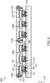
- FIGs. 3A-3C illustrate cross-sectional views of different stages of a process for manufacturing the light-emitting device 100A in accordance with some embodiments of the present disclosure.
- the process begins by providing the first substrate 200 shown in FIG. 3A .
- the light-emitting module 300a and the light-emitting module 300b may be transferred from a carrier substrate (not shown) to the first substrate 200.
- the light-emitting module 300a and the light-emitting module 300b may be disposed on (or attached to) the first substrate 200 in the same step or different steps.
- the second substrate 400 may be disposed on the first substrate 200, and the light-emitting modules (such as 300a and/or 300b), and the auxiliary electrodes 330 may be disposed between the first substrate 200 and the second substrate 400.
- the light-emitting modules such as 300a and/or 300b
- the auxiliary electrodes 330 may be disposed between the first substrate 200 and the second substrate 400.
- FIG. 4 illustrates a cross-sectional view of a light-emitting device 100B in accordance with some embodiments of the present disclosure.
- the light-shielding structure 410a may be disposed in (or embedded in) the second circuit layer 430 of the light-emitting device 100B.
- the second circuit layer 430 may form a plurality of openings O1, and the light-shielding structure 410a may be disposed in the openings O1 of the second circuit layer 430.
- FIG. 5 illustrates a cross-sectional view of a light-emitting device 100C in accordance with some embodiments of the present disclosure.
- the light-emitting device 100C may include a light-shielding structure 410b having a main portion 411a and a protruding portion 411b, and the protruding portion 411b connects with the main portion 411a.
- the light-shielding structure 410b may be disposed between two adjacent ones of the light-emitting modules (such as the light-emitting modules 300a and 300b) in the normal direction Z.
- the protruding portion 411b of the light-shielding structure 410b may extend into at least part of the gap G. In some embodiments ( Fig.5 ), the protruding portion 411b of the light-shielding structure 410b may be in contact with a part of the light-emitting module 300a and/or a part of the light-emitting module 300b. For example, the protruding portion 411b may be in contact with a part of the fixing layers 320 of the light-emitting module 300a and/or a part of the fixing layers 320 of the light-emitting module 300b.
- the material of the light-shielding structure 410b may include resins, glass pastes, black pigments, metallic particles (e.g. nickel, aluminum, molybdenum or alloys thereof), metal oxide particles (e.g. chromium oxide) metal nitride particles (e.g. chromium nitride), other material or a combination thereof, but it is not limited.
- the protruding portion 411b may be extended and/or in contact with the first circuit layer 210. In some embodiments (not shown), the protruding portion 411b may be disposed in (or embedded in) the first circuit layer 210. In some embodiments, the material of the light-shielding structure 410b may include conductive materials (such as metal) for electrically connecting to the elements disposed in the first circuit layer 210 (or the second circuit layer 430). In some embodiments, the material of the light-shielding structure 410b may include reflective materials (such as metal or alloys) for reducing an interference of the lights emitted from adjacent light-emitting modules.
- the shape of the light-shielding structure may include rectangular, trapezoidal (such as positive trapezoid or inverted trapezoid), columnar or other irregular shape, but it is not limited.
- the shape (or the layout) of the light-shielding structure in the normal direction Z may be modified according to the requirements of design.
- the light-shielding structure 410d may have a circle shape in the boundary of the light-emitting modules 300 as shown in FIG.6 .
- a plurality of light-shielding structures 410d may be separated from each other.
- the light-shielding structure 410d may include a line pattern, a mesh pattern, an island pattern, other pattern or a combination thereof, but it is not limited.
- the light-shielding structure 410d is in one of mesh pattern, line pattern and island pattern.
- FIG. 7 illustrates a cross-sectional view of a light-emitting device 100E in accordance with some embodiments of the present disclosure.
- the light-emitting device 100E may include a light-shielding structure 410e and the light-emitting units 310', and the electrodes 314 of the light-emitting units 310' and the electrodes 315 of the light-emitting units 310' may be electrically connected with the first circuit layer 210 through the pads 220.
- the light-shielding material may be disposed on the light-emitting modules 300 to form the light-shielding structure 410e.
- the light-shielding material may be disposed on the light-emitting modules 300 by coating method or other methods.
- a protruding portion 412 of the light-shielding structure 410e may be defined by a portion of light-shielding structure 410e disposed between the fixing layers 320 of two adjacent ones of the light-emitting modules 300.
- a protective layer 510 may be disposed on the first substrate 200 to cover the light-emitting module 300a, light-emitting module 300b and/or the light-shielding structure 410e.
- an area of the protective layer 510 may be the same as or different from an area of the first substrate 200 in the normal direction Z.
- the material of the protective layer 510 may include organic materials or inorganic materials, such as silicon nitride, silicon oxide, Al2O3 or resin, but it is not limited.
- the protective layer 510 may be a single layer or multilayer.
- the light-shielding structure 410e may cover (or overlap with) a portion of the fixing layers 320 in the normal direction Z.
- a height H1 of the protruding portion 412 may be modified.
- the height H1 of the protruding portion 412 may be greater than or equal to the height H2 of the fixing layer 320.
- the height H1 of the protruding portion 412 may be less than the height H2 of the fixing layer 320.
- the height H1 may be defined by a maximum height of the protruding portion 412 in the normal direction Z.
- the height H2 may be defined by a maximum height of the fixing layer 320 in the normal direction Z.
- the height H1 and/or height H2 may be measured from a scanning electron microscope (SEM) image along any direction perpendicular with the normal direction Z. In some embodiments (not shown), the height H2 of the fixing layer 320 may be adjusted according to demand. In some embodiments (not shown), the fixing layer 320 may cover the light-emitting unit 310, and the fixing layer 320 may exposure part of the electrodes 314 and part the electrodes 315 for electrically connecting to the pads 220.
- SEM scanning electron microscope
- FIG. 8 illustrates a cross-sectional view of a light-emitting device 100E' in accordance with some embodiments of the present disclosure.
- the fixing layers 320 of the light-emitting module 300a (or light-emitting module 300b) of the light-emitting device 100E' may have openings disposed between the light-emitting units 310', and the openings may not overlap with the light-emitting unit 310'.
- the material of the fixing layers 320 of the light-emitting device 100E' may include silicon, but it is not limited.
- the material of the fixing layers 320 of the light-emitting device 100E may include sapphire, glass, PI, but it is not limited
- the electrodes, such as the electrodes 314 and 315, of the light-emitting unit 310' may be electrically connected to the pads 220 disposed on the first substrate 200. Therefore, the second circuit layer 430 and/or the second substrate 400 may be removed in this embodiment.
- FIG. 9 illustrates a cross-sectional view of a light-emitting device 100F in accordance with some embodiments of the present disclosure.
- the light-emitting device 100F may further include an optical sensor 520 and reflective layers 530.
- the optical sensor 520 may be disposed between the first light-emitting module 300a and the second light-emitting module 300b, or the optical sensor 520 may at least partially overlap with (or cover) the gap G in the normal direction Z.
- the optical sensor 520 may overlap with the light-shielding structure 410f in the normal direction Z.
- the optical sensor 520 may be disposed to sense the light emitted from the light-emitting units 310'. For example, when the light-emitting unit 310 of the light-emitting module 300a emits a light L1, the light L1 may be incident to the reflective layer 530 and then be reflected to the optical sensor 520. Similarly, the light-emitting unit 310 of the light-emitting module 300b emits a light L2, the light L2 may be incident to the reflective layer 530 and then be reflected to the optical sensor 520.
- the optical sensor 520 may collects light L1 and/or the light L2, and the operating condition of the light-emitting unit 310 of the light-emitting module 300a and/or the light-emitting module 300b may be modified according to an intensity of light L1 and/or an intensity of L2 collected by the optical sensor 520, but it is not limited. Therefore, the differences between the light-emitting modules 300 (such as the light-emitting modules 300a and 300b) may be reduced or the uniformity of brightness may be increased.
- the optical sensor 520 may include a P-intrinsic-N diode (PIN diode) or a thin film transistor (TFT).
- the optical sensor 520 may include GaN, GaAs, InAs, AlGaAs, GaInN or another suitable material.
- the material of the reflective layer 530 may include metal, such as Al, Cu, Ag, Au or another suitable reflective material.
- the optical sensor 520 may be overlapped with the light-shielding structure 410f to reduce a possibility of the optical sensor 520 affected by surrounding light, or to increase the accuracy of the optical sensor 520.
- the reflective layers 530 may be overlapped with the light-shielding structure 410f.
- the reflective layers 530 may be disposed between the light-shielding structure 410f and the optical sensor 520 in the Z direction.
- the light-emitting device 100G may include a plurality of driving units 230.
- One of the driving units 230 may be electrically connected to one of the light-emitting units 310.
- the driving units 230 may include a TFT.
- the driving unit 230 may include a gate electrode 231, a source electrode 232, a drain electrode 233 and a channel region 234.
- the gate electrode 231 may be disposed in a first circuit layer 210; the source electrode 232, the drain electrode 233 and the channel region 234 may be disposed in a circuit layer 211.
- the dielectric layers 211 and 212 may be a portion of the first circuit layer 210.
- the material of the gate electrode 231 may include metal, such as copper (Cu), aluminum (Al), molybdenum (Mo), tungsten (W), gold (Au), chromium (Cr), nickel (Ni), platinum (Pt), titanium (Ti), other suitable materials or combinations thereof, but it is not limited.
- the source electrode 232, the drain electrode 233 and/or the channel region 234 may be a portion of a semiconductor layer, the source electrode 232 and the drain electrode 233 may be doped, and the channel region 234 may not be doped, but it is not limited. In some embodiment, the channel region 234 may be overlapping with the gate electrode 231.
- the driving units 230 may include amorphous silicon, polysilicon such as low-temp polysilicon (LTPS), metal oxide or another suitable material.
- the metal oxide may include indium gallium zinc oxide (IGZO), indium zinc oxide (IZO), indium gallium zinc tin oxide (IGZTO), low temperature polycrystalline silicon and oxide semiconductor (LTPO), other suitable materials or a combination thereof, but it is not limited.
- the light-emitting unit 310 may be electrically connected to the driving unit 230 through a conductive though hole 240.
- the light-emitting unit 310 of the light-emitting modules 300a and the light-emitting units 310 of the light-emitting unit 300b may be electrically connected through the second circuit layer 430, but it is not limited.
- the light-emitting units 310 may be individually controlled through the corresponding driving unit 230.
- the light-emitting device 100H may include a light-adjusting unit 450.
- the light-adjusting unit 450 may be disposed between the second substrate 400 and the second circuit layer 430, but it is not limited.
- the light-adjusting unit 450 may be disposed adjacent to the light-shielding structure 460.
- the light-shielding structures 460 may be interlaced to each other to form a grid shape, the grid shape encloses some openings, and the light-adjusting units 450 may be disposed corresponding to the openings.
- the material of the light-adjusting unit 450 may include quantum dot, fluorescent material, color filter material, phosphorescent material, another suitable materials or a combination thereof, but not limited.
- the light-adjusting unit 450 may be an organic layer or an inorganic layer blended with a quantum dot.
- the quantum dot may include zinc, cadmium, selenium, sulfur, InP, GaSb, GaAs, CdSe, CdS, ZnS, (CH 3 NH 3 )EuI 3 , KEuI 3 , CsEuI 3 , or RbEuI 3 or a combination thereof, but it is not limited.
- the shape of the light-adjusting units 450 may include strip shape, for example, at least one of the light-adjusting units 450 may be corresponding to (or overlap with) a plurality of the light-emitting units 310 in the normal direction Z.
- two adjacent ones of the light-emitting units 310 may be electrically connected through a wire 250.
- the wire 250 may be disposed in the first circuit layer 210 (or the second circuit layer 430).
- two adjacent ones of the light-emitting units 310 may be electrically connected through the auxiliary electrode 330, and the auxiliary electrode 330 may be electrically connected with a common electrode (not shown).
- one of the light-adjusting units 450 may be corresponding to (or overlap with) one sub-pixel SP.
- one of the sub-pixels SP may include at least one light-emitting unit 310. For example ( Fig.
- one of the sub-pixels SP may include two light-emitting units 310, but it is not limited. It should be noted that Fig.11 only shows the light-emitting module 300a, the light-emitting module 300b may be similar to the light-emitting module 300a, and there is a gap G between the light-emitting module 300a and the light-emitting module 300b.
- FIG. 12 illustrates a cross-sectional view of a light-emitting device 100I in accordance with some embodiments of the present disclosure.
- the light-emitting unit 310 of the light-emitting module 300a and the light-emitting unit 310 of the light-emitting module 300b may be electrically connected through a wire 260.
- the wire 260 may be disposed in the first circuit layer 210.
- the wire 260 may be disposed in the second circuit layer 430.
- the first substrate 200 and/or the second substrate 400 of the light-emitting device 100J may include flexible substrates.
- the ratio of Young's modulus between the fixing layer 320 and the first substrate 200 may be in a range between 0.8 to 1,2 (0.8 ⁇ ratio ⁇ 1.2), but it is not limited.
- the ratio of Young's modulus between the second substrate 400 and the first substrate 200 may be in a range between 0.8 to 1,2 (0.8 ⁇ ratio ⁇ 1.2), but it is not limited.
- the light-emitting device 100J may further include a supporting film 270.
- the first substrate 200 may be disposed between the supporting film 270 and the second substrate 400.
- the supporting film 270 may overlap with the light-emitting module 300a and/or the light-emitting module 300b in the normal direction Z. In some embodiments ( FIG. 13 ), the supporting film 270 does not overlap with the gap G in the normal direction Z.
- the material of the supporting film 270 may include glass, polymer, plastic or another material, but it is not limited.
- the light-emitting device 100K further includes light-shielding structures 470.
- the light-shielding structure 470 may be disposed between two adjacent ones of the light-emitting units 310. In some embodiments, the light-shielding structure 470 may be disposed between two adjacent ones of the sub-pixels.
- the light-shielding structures 470 may be disposed for reducing the interference of the light of adjacent light-adjusting unit 450 or the light emitted from the surrounding.
- the light-shielding structures (such as 410a, 410b, 410c, 410d, 410e and 410f) disposed corresponding to (or overlapping to) the gap G in the normal direction Z may be referred as the first portion of the light-shielding structure, the light-shielding structures (such as 460 and 470) disposed between two adjacent ones of the light-adjusting units 450 (refer to Fig. 11 ) or two adjacent ones of the light-emitting units 310 (such as sub-pixels) in the normal direction Z may be referred as the second portion of the light-shielding structures.
- the gap G may be filled with the air or other suitable materials (such as adhesive materials, buffer materials or other filling component, but it is not limited).
Abstract
Description
- The present disclosure relates to a light-emitting device, and in particular to a light-emitting device that includes a plurality of light-emitting modules.
- Light-emitting devices are widely used. The performance and/or quality of these light-emitting devices need to be continually improved. Therefore, a new light-emitting device with improved performance and/or quality is needed.
- In accordance with some embodiments of the present disclosure, a light-emitting device is provided. The light-emitting device includes a first substrate and a second substrate. The second substrate including a light-shielding structure. The light-emitting device further includes a first light-emitting module and a second light-emitting module being adjacent to each other. The first light-emitting module and the second light-emitting module are disposed between the first substrate and the second substrate. The first light-emitting module and the second light-emitting module are spaced apart by a gap, and the light-shielding structure at least partially covers the gap in a top view direction of the light-emitting device.
- In accordance with some embodiments of the present disclosure, a light-emitting device is provided. The light-emitting device includes a first substrate. The light-emitting device includes a first light-emitting module and a second light-emitting module being adjacent to each other. The first light-emitting module and the second light-emitting module are disposed on the first substrate. The light-emitting device further includes a light-shielding structure disposed on the first light-emitting module and the second light-emitting module. The first light-emitting module and the second light-emitting module are spaced apart by a gap, and the light-shielding structure at least partially covers the gap in a top view direction of the light-emitting device.
- In accordance with some embodiments of the present disclosure, a method for manufacturing a light-emitting device. The method includes providing a first substrate. The method also includes transferring a first light-emitting module with a plurality of first light-emitting units and a second light-emitting module with a plurality of second light-emitting units to the first substrate. The method further includes providing a second substrate on the first light-emitting module and the second light-emitting module. The plurality of first light-emitting units connected with each other through a first fixing layer, and the plurality of second light-emitting units connected with each other through a second fixing layer.
- A detailed description is given in the following embodiments with reference to the accompanying drawings.
- The disclosure may be understood by reading the subsequent detailed description and examples with references made to the accompanying drawings, wherein:
-
FIG. 1A-AD illustrate top views of a light-emitting device and its elements in accordance with some embodiments of the present disclosure. -
FIG. 2 illustrates a cross-sectional view of the light-emitting device along the line A-A' ofFIG. 1A in accordance with some embodiments of the present disclosure. -
FIGs. 3A-3C illustrate cross-sectional views of different stages of a process for manufacturing the light-emitting device in accordance with some embodiments of the present disclosure. -
FIG. 4 illustrates a cross-sectional view of a light-emitting device in accordance with some embodiments of the present disclosure. -
FIG. 5 illustrates a cross-sectional view of a light-emitting device in accordance with some embodiments of the present disclosure. -
FIG. 6 illustrates a top view of a light-emitting device in accordance with some embodiments of the present disclosure. -
FIG. 7 illustrates a cross-sectional view of a light-emitting device in accordance with some embodiments of the present disclosure. -
FIG. 8 illustrates a cross-sectional view of a light-emitting device in accordance with some embodiments of the present disclosure. -
FIG. 9 illustrates a cross-sectional view of a light-emitting device in accordance with some embodiments of the present disclosure. -
FIG. 10 illustrates a cross-sectional view of a light-emitting device in accordance with some embodiments of the present disclosure. -
FIG. 11 illustrates a cross-sectional view of a light-emitting device in accordance with some embodiments of the present disclosure. -
FIG. 12 illustrates a cross-sectional view of a light-emitting device in accordance with some embodiments of the present disclosure. -
FIG. 13 illustrates a cross-sectional view of a light-emitting device in accordance with some embodiments of the present disclosure. -
FIG. 14 illustrates a cross-sectional view of a light-emitting device in accordance with some embodiments of the present disclosure. - The light-emitting device of the present disclosure and the manufacturing method thereof are described in detail in the following description. In the following detailed description, for purposes of explanation, numerous specific details and embodiments are set forth in order to provide a thorough understanding of the present disclosure. It will be apparent, however, that the exemplary embodiments set forth herein are used merely for the purpose of illustration, and the inventive concept may be embodied in various forms without being limited to those exemplary embodiments. In addition, the drawings of different embodiments may use like and/or corresponding numerals to denote like and/or corresponding elements. However, the use of like and/or corresponding numerals in the drawings of different embodiments does not suggest any correlation between different embodiments. In addition, in this specification, expressions such as "first material layer disposed above/on/over a second material layer", may indicate the direct contact of the first material layer and the second material layer, or it may indicate a non-contact state with one or more intermediate layers between the first material layer and the second material layer. In the above situation, the first material layer may not be in direct contact with the second material layer.
- It should be understood that, although the terms first, second, third etc. may be used herein to describe various elements, components, regions, layers, portions and/or sections, these elements, components, regions, layers, portions and/or sections should not be limited by these terms. These terms are only used to distinguish one element, component, region, layer, portion or section from another element, component, region, layer or section. Thus, a first element, component, region, layer, portion or section discussed below could be termed a second element, component, region, layer, portion or section without departing from the teachings of the present disclosure.
- It should be understood that this description of the exemplary embodiments is intended to be read in connection with the accompanying drawings, which are to be considered part of the entire written description. The drawings are not drawn to scale. In addition, structures and devices are shown schematically in order to simplify the drawing. In the drawings, some components may be omitted for clarity. Moreover, some components in the drawings may be eliminated as another embodiment of the present disclosure.
- The terms "about", "substantially", "equal", or "same" generally mean within 20% of a given value or range, or mean within 10%, 5%, 3%, 2%, 1%, or 0.5% of a given value or range..
- Unless defined otherwise, all technical and scientific terms used herein have the same meaning as commonly understood by one of ordinary skill in the art to which this disclosure belongs. It should be appreciated that, in each case, the term, which is defined in a commonly used dictionary, should be interpreted as having a meaning that conforms to the relative skills of the present disclosure and the background or the context of the present disclosure, and should not be interpreted in an idealized or overly formal manner unless so defined.
- In addition, in some embodiments of the present disclosure, terms concerning attachments, "connected" and "interconnected," refer to a relationship wherein structures are secured or attached to one another either directly or indirectly through intervening structures, as well as both movable or rigid attachments or relationships, unless expressly described otherwise.
- In addition, the phrase "in a range from a first value to a second value" indicates the range includes the first value, the second value, and other values in between.
- In addition, the term "cover" includes the meaning of "cover partially", or "cover completely". The term "overlap with" includes the meaning of "overlap partially" or "overlap completely".
- Refer to
FIGs. 1A-1D , which illustrate top views of a light-emittingdevice 100A and its elements in accordance with some embodiments of the present disclosure. It should be appreciated that some elements are omitted inFIGs. 1A-1D for brevity. The light-emittingdevice 100A may include afirst substrate 200, a light-emittingmodule 300 and asecond substrate 400, which are individually illustrated inFIGs. 1B ,1C and 1D . Thefirst substrate 200 or thesecond substrate 400 may include a rigid substrate (such as a glass substrate or a quartz substrate) or a flexible substrate (such as a plastic substrate), but not limited thereto. The material of the plastic substrate may include polyimide (PI), polycarbonate (PC) or polyethylene terephthalate (PET), but not limited thereto. - In some embodiments (refer to
FIGs. 1A-1D and2 ), the light-emittingmodule 300 may be disposed between thefirst substrate 200 and thesecond substrate 400. In some embodiments (refer toFIGs. 1A-1D and2 ), the light-emittingmodule 300 may include a plurality of light-emittingunits 310 and afixing layer 320. In some embodiments, the light-emittingunits 310 may be fixed through thefixing layer 320. In some embodiments, the light-emittingunits 310 may be connected to each other through thefixing layer 320. It is appreciated that the number of the light-emittingunit 310 of the light-emittingmodule 300 is merely an exemplary, and the scope of the elements in the disclosure is not limited. In some embodiments, the plurality of light-emittingunits 310 and thefixing layer 320 may be disposed on a growth substrate (not shown), and the plurality of light-emittingunits 310 and thefixing layer 320 may be transferred from the growth substrate to a carrier substrate (not shown). In some embodiments, the light-emittingunits 310 and thefixing layer 320 are removed from the growth substrate (not shown), thefixing layer 320 is cut to form a plurality of light-emittingmodules 300. As a result, each light-emittingmodule 300 may include multiple light-emittingunits 310 that are connected by thefixing layer 320. In some embodiments, the material of thefixing layer 320 may include a molding compound, such as epoxy resin, silicon wafer, sapphire, glass, PI, other suitable materials or combinations thereof, but it is not limited. In some embodiments, thefixing layer 320 may include a single layer or a multilayer, but it is not limited. - In some embodiments (refer to
FIGs. 1A-1D and2 ), thesecond substrate 400 may include a light-shielding structure 410a, but it is not limited. In some embodiments, the light-shielding structure 410a may include black photoresist, black printing ink, black resin, organic resin, glass paste, other suitable material or combinations thereof, but it is not limited. In some embodiments, the light-shielding structure 410a may have a mesh shaped, but it is not limited. The light-shielding structure 410a may include a plurality ofopenings 420. In some embodiments, theopening 420 may correspond to the light-emittingmodule 300 As shown inFIG. 1A , in top view direction (a normal direction Z of the first substrate 200) of the light-emitting device, the light-emittingmodules 300 overlaps with theopenings 420 of the light-shielding structure 410a. It should be appreciated that in order to clearly illustrate the position relation of the light-emittingmodule 300 and the light-shielding structure 410a, the light-emittingmodules 300 may be disposed on the left side of the light-emittingdevice 100A are illustrated. Actually, one of theopenings 420 may overlap with one of the light-emitting modules (such as the light-emittingmodule 300 or the light-emitting unit 310) in the normal direction Z of thefirst substrate 200, but it is not limited. - Refer to
FIG. 2 , which illustrates a cross-sectional view of the light-emittingdevice 100A along the line A-A' ofFIG. 1A in accordance with some embodiments of the present disclosure. As shown inFIG. 2 , the light-emittingmodule 300a and the light-emittingmodule 300b are disposed between thefirst substrate 200 and thesecond substrate 400, but it is not limited. Thefirst substrate 200 may include afirst circuit layer 210. Thefirst circuit layer 210 may include dielectric layers and conductive wires disposed therein. The active elements or the passive elements (not shown) may be disposed in thefirst circuit layer 210. The active elements may include thin film transistor (TFT) or another suitable element, but it is not limited. Thefirst substrate 200 may include a plurality ofpads 220 electrically connected to thefirst circuit layer 210. - The
second substrate 400 may include asecond circuit layer 430. Thesecond circuit layer 430 may include dielectric layers and conductive wires disposed therein. The active elements or passive elements (not shown) may be disposed in thesecond circuit layer 430. Thesecond substrate 400 may include a plurality ofpads 440 electrically connected to thesecond circuit layer 430. The material of thepad 220 and/or thepad 440 may include copper (Cu), aluminum (Al), molybdenum (Mo), tungsten (W), gold (Au), chromium (Cr), nickel (Ni), platinum (Pt), titanium (Ti) or other suitable materials or combinations thereof, but it is not limited. In some embodiments (refer toFIG2 ), the light-shielding structure 410a may be disposed between thesecond circuit layer 430 andfirst substrate 200, but it is not limited. In some embodiments (not shown), the light-shielding structure 410a may be disposed between thesecond circuit layer 430 and thesecond substrate 400. In some embodiments (not shown), the light-shielding structure 410a may be disposed between the light-emittingmodule 300a (and/or the light-emittingmodule 300b) and thefirst substrate 200. In some embodiments (not shown), the light-shielding structure 410a may be disposed between the light-emittingmodule 300a (and/ or the light-emittingmodule 300b) and thefirst circuit layer 210. - The light-emitting
unit 310 may include a light-emitting diode (LED), a micro light-emitting diode (µLED), a mini light-emitting diode (mini-LED), quantum dot LED (QD-LED), or other suitable materials, but it is not limited. - As shown in
Fig. 2 , the light-emittingunit 310 may include a light-emittinglayer 311, semiconductor layers 312 and 313,electrodes electrodes electrodes unit 310 may be electrically connected to thefirst circuit layer 210 through thepad 220. The light-emittingunit 310 may be electrically connected to thesecond circuit layer 430 through thepad 440. In some embodiments, the material of thepad 220 and thepad 440 may be the same or different. In some embodiments (Fig.2 ), the light-emittingdevice 100A may include anauxiliary electrode 330. In some embodiments, theauxiliary electrode 330 may be electrically connected to the light-emittingunit 310. In some embodiments, theauxiliary electrode 330 may be electrically connected to a common electrode (not shown), but it is not limited. In some embodiments, theauxiliary electrode 330 may be electrically connected to thepad 440. In some embodiments, the common electrode (not shown) may be disposed on the second substrate 400 (or the first substrate 200). In some embodiments, the common electrode (not shown) may be disposed in the second circuit layer 430 (or first circuit layer 210). The material of theauxiliary electrode 330 may include copper (Cu), aluminum (Al), titanium (Ti), silver (Ag), gold (Au), tin (Sn), lead (Pb), other suitable materials or combinations thereof, but it is not limited. - In some embodiments (
Fig.2 ), thefixing layer 320 may be adjacent to the light-emittingunits 310. In some embodiments, there is a gap G between two adjacent light-emittingmodules 300, such as the light-emittingmodules layers 320 of two adjacent light-emittingmodules 300 in a cross-sectional view (referFig2 ). The cross-sectional image may be along any direction perpendicular with the normal direction Z. In some embodiments, the width of gap G may be defined by using an OM image to measure a minimum space between the fixinglayers 320 of two adjacent ones of the light-emittingmodules 300 in any direction perpendicular with the normal direction Z (referFig.1A ). In some embodiments (Fig.2 ), in the normal direction Z of thefirst substrate 200, the light-shielding structure 410a may overlap with the gap G. In some embodiments (Fig.2 ), the light-shielding structure 410a may cover the gap G in the normal direction Z. In some embodiments (FIG. 2 ), in a cross-sectional view, a width W of the light-shielding structure 410a in any direction perpendicular with the normal direction Z (such as direction X or direction Y) may be greater than or equal to a width of the gap G in the same direction. In some embodiments, a width of the gap G may be greater than 0 and less or equal to 5mm (0mm< the width of the gap G≦5mm), The width W of the light-shielding structure 410a may defined by a minimum width of the light-shielding structure 410a. The gap G may be used as a space for expansion of the light-emittingunit 310 or reducing collision, but it is not limited. In some embodiments (Fig.2 ), the light-shielding structure 410a may overlap with a portion of thefixing layer 320 in the normal direction Z. - In this disclosure, the light-emitting
module 300 may include the light-emittingunit 310 and thefixing layer 320. More specifically, the light-emittingmodules 300 may be defined by thefixing layer 320. For example, the fixinglayers 320 of the light-emittingmodule 300a and the light-emittingmodule 300b are separated from each other, so the light-emittingmodule 300a and the light-emittingmodule 300b could be defined as two different light-emitting modules. - Refer to
FIGs. 3A-3C , which illustrate cross-sectional views of different stages of a process for manufacturing the light-emittingdevice 100A in accordance with some embodiments of the present disclosure. - The process begins by providing the
first substrate 200 shown inFIG. 3A . As shown inFIGs. 3B , the light-emittingmodule 300a and the light-emittingmodule 300b may be transferred from a carrier substrate (not shown) to thefirst substrate 200. The light-emittingmodule 300a and the light-emittingmodule 300b may be disposed on (or attached to) thefirst substrate 200 in the same step or different steps. - As shown in
FIG. 3C , thesecond substrate 400 may be disposed on thefirst substrate 200, and the light-emitting modules (such as 300a and/or 300b), and theauxiliary electrodes 330 may be disposed between thefirst substrate 200 and thesecond substrate 400. - Refer to
FIG. 4 , which illustrates a cross-sectional view of a light-emittingdevice 100B in accordance with some embodiments of the present disclosure. In some embodiments, one of the differences between the light-emittingdevice 100A and the light-emittingdevice 100B is that the light-shielding structure 410a may be disposed in (or embedded in) thesecond circuit layer 430 of the light-emittingdevice 100B. In some embodiments, thesecond circuit layer 430 may form a plurality of openings O1, and the light-shielding structure 410a may be disposed in the openings O1 of thesecond circuit layer 430. - . Refer to
FIG. 5 , which illustrates a cross-sectional view of a light-emittingdevice 100C in accordance with some embodiments of the present disclosure. In some embodiments, one of the differences between the light-emittingdevice 100A and the light-emittingdevice 100C is that the light-emittingdevice 100C may include a light-shieldingstructure 410b having amain portion 411a and a protrudingportion 411b, and the protrudingportion 411b connects with themain portion 411a. In some embodiments, the light-shieldingstructure 410b may be disposed between two adjacent ones of the light-emitting modules (such as the light-emittingmodules Fig.5 ), the protrudingportion 411b of the light-shieldingstructure 410b may extend into at least part of the gap G. In some embodiments (Fig.5 ), the protrudingportion 411b of the light-shieldingstructure 410b may be in contact with a part of the light-emittingmodule 300a and/or a part of the light-emittingmodule 300b. For example, the protrudingportion 411b may be in contact with a part of the fixinglayers 320 of the light-emittingmodule 300a and/or a part of the fixinglayers 320 of the light-emittingmodule 300b. In some embodiments, the material of the light-shieldingstructure 410b may include resins, glass pastes, black pigments, metallic particles (e.g. nickel, aluminum, molybdenum or alloys thereof), metal oxide particles (e.g. chromium oxide) metal nitride particles (e.g. chromium nitride), other material or a combination thereof, but it is not limited. - In some embodiments (not shown), the protruding
portion 411b may be extended and/or in contact with thefirst circuit layer 210. In some embodiments (not shown), the protrudingportion 411b may be disposed in (or embedded in) thefirst circuit layer 210. In some embodiments, the material of the light-shieldingstructure 410b may include conductive materials (such as metal) for electrically connecting to the elements disposed in the first circuit layer 210 (or the second circuit layer 430). In some embodiments, the material of the light-shieldingstructure 410b may include reflective materials (such as metal or alloys) for reducing an interference of the lights emitted from adjacent light-emitting modules. - In some embodiments, in cross-sectional view, the shape of the light-shielding structure may include rectangular, trapezoidal (such as positive trapezoid or inverted trapezoid), columnar or other irregular shape, but it is not limited.
- In some embodiments, the shape (or the layout) of the light-shielding structure in the normal direction Z may be modified according to the requirements of design. For example, the light-shielding
structure 410d may have a circle shape in the boundary of the light-emittingmodules 300 as shown inFIG.6 . In some embodiments (FIG. 6 ), a plurality of light-shieldingstructures 410d may be separated from each other. In some embodiments, the light-shieldingstructure 410d may include a line pattern, a mesh pattern, an island pattern, other pattern or a combination thereof, but it is not limited. In some embodiments, the light-shieldingstructure 410d is in one of mesh pattern, line pattern and island pattern. - Refer to
FIG. 7 , which illustrates a cross-sectional view of a light-emittingdevice 100E in accordance with some embodiments of the present disclosure. One of the differences between the light-emittingdevice 100A and the light-emittingdevice 100E is that the light-emittingdevice 100E may include a light-shielding structure 410e and the light-emitting units 310', and theelectrodes 314 of the light-emitting units 310' and theelectrodes 315 of the light-emitting units 310' may be electrically connected with thefirst circuit layer 210 through thepads 220. In some embodiments (FIG. 7 ), after the light-emittingmodules 300 are disposed on thefirst substrate 200, the light-shielding material may be disposed on the light-emittingmodules 300 to form the light-shielding structure 410e. In some embodiments, the light-shielding material may be disposed on the light-emittingmodules 300 by coating method or other methods. A protruding portion 412 of the light-shielding structure 410e may be defined by a portion of light-shielding structure 410e disposed between the fixinglayers 320 of two adjacent ones of the light-emittingmodules 300. After the light-shieldingstructures 410e are disposed, aprotective layer 510 may be disposed on thefirst substrate 200 to cover the light-emittingmodule 300a, light-emittingmodule 300b and/or the light-shielding structure 410e. In some embodiments, an area of theprotective layer 510 may be the same as or different from an area of thefirst substrate 200 in the normal direction Z. In some embodiments, the material of theprotective layer 510 may include organic materials or inorganic materials, such as silicon nitride, silicon oxide, Al2O3 or resin, but it is not limited. Theprotective layer 510 may be a single layer or multilayer. - In some embodiments (
Fig.7 ), the light-shielding structure 410e may cover (or overlap with) a portion of the fixinglayers 320 in the normal direction Z.. In some embodiments, a height H1 of the protruding portion 412 may be modified. In some embodiments (not shown), the height H1 of the protruding portion 412 may be greater than or equal to the height H2 of thefixing layer 320. In some embodiments, the height H1 of the protruding portion 412 may be less than the height H2 of thefixing layer 320. The height H1 may be defined by a maximum height of the protruding portion 412 in the normal direction Z. The height H2 may be defined by a maximum height of thefixing layer 320 in the normal direction Z. The height H1 and/or height H2 may be measured from a scanning electron microscope (SEM) image along any direction perpendicular with the normal direction Z. In some embodiments (not shown), the height H2 of thefixing layer 320 may be adjusted according to demand. In some embodiments (not shown), thefixing layer 320 may cover the light-emittingunit 310, and thefixing layer 320 may exposure part of theelectrodes 314 and part theelectrodes 315 for electrically connecting to thepads 220. - Refer to
FIG. 8 which illustrates a cross-sectional view of a light-emittingdevice 100E' in accordance with some embodiments of the present disclosure. One of the differences between the light-emittingdevice 100E and the light-emittingdevice 100E' is that, the fixinglayers 320 of the light-emittingmodule 300a (or light-emittingmodule 300b) of the light-emittingdevice 100E' may have openings disposed between the light-emitting units 310', and the openings may not overlap with the light-emitting unit 310'. The material of the fixinglayers 320 of the light-emittingdevice 100E' may include silicon, but it is not limited. In some embodiments (FIG. 7 ), the material of the fixinglayers 320 of the light-emittingdevice 100E may include sapphire, glass, PI, but it is not limited - As shown in
FIG. 9 , the electrodes, such as theelectrodes pads 220 disposed on thefirst substrate 200. Therefore, thesecond circuit layer 430 and/or thesecond substrate 400 may be removed in this embodiment. - Refer to
FIG. 9 , which illustrates a cross-sectional view of a light-emittingdevice 100F in accordance with some embodiments of the present disclosure. In some embodiments, one of the differences between the light-emittingdevice 100A and the light-emittingdevice 100F is that the light-emittingdevice 100F may further include anoptical sensor 520 andreflective layers 530. In some embodiments (Fig.9 ), theoptical sensor 520 may be disposed between the first light-emittingmodule 300a and the second light-emittingmodule 300b, or theoptical sensor 520 may at least partially overlap with (or cover) the gap G in the normal direction Z. In some embodiments (Fig.9 ), theoptical sensor 520 may overlap with the light-shieldingstructure 410f in the normal direction Z. Theoptical sensor 520 may be disposed to sense the light emitted from the light-emitting units 310'. For example, when the light-emittingunit 310 of the light-emittingmodule 300a emits a light L1, the light L1 may be incident to thereflective layer 530 and then be reflected to theoptical sensor 520. Similarly, the light-emittingunit 310 of the light-emittingmodule 300b emits a light L2, the light L2 may be incident to thereflective layer 530 and then be reflected to theoptical sensor 520. Theoptical sensor 520 may collects light L1 and/or the light L2, and the operating condition of the light-emittingunit 310 of the light-emittingmodule 300a and/or the light-emittingmodule 300b may be modified according to an intensity of light L1 and/or an intensity of L2 collected by theoptical sensor 520, but it is not limited. Therefore, the differences between the light-emitting modules 300 (such as the light-emittingmodules - In some embodiments, the
optical sensor 520 may include a P-intrinsic-N diode (PIN diode) or a thin film transistor (TFT). In some embodiments, theoptical sensor 520 may include GaN, GaAs, InAs, AlGaAs, GaInN or another suitable material. In some embodiments, the material of thereflective layer 530 may include metal, such as Al, Cu, Ag, Au or another suitable reflective material. - In some embodiments, the
optical sensor 520 may be overlapped with the light-shieldingstructure 410f to reduce a possibility of theoptical sensor 520 affected by surrounding light, or to increase the accuracy of theoptical sensor 520. In some embodiments (Fig.9 ), thereflective layers 530 may be overlapped with the light-shieldingstructure 410f. In some embodiments (Fig.9 ), thereflective layers 530 may be disposed between the light-shieldingstructure 410f and theoptical sensor 520 in the Z direction. - Refer to
FIG. 10 , which illustrates a cross-sectional view of a light-emittingdevice 100G in accordance with some embodiments of the present disclosure. In some embodiments, the light-emittingdevice 100G may include a plurality of drivingunits 230. One of the drivingunits 230 may be electrically connected to one of the light-emittingunits 310. - In some embodiment, the driving
units 230 may include a TFT. For example, the drivingunit 230 may include agate electrode 231, asource electrode 232, adrain electrode 233 and achannel region 234. Thegate electrode 231 may be disposed in afirst circuit layer 210; thesource electrode 232, thedrain electrode 233 and thechannel region 234 may be disposed in acircuit layer 211. Thedielectric layers first circuit layer 210. The material of thegate electrode 231 may include metal, such as copper (Cu), aluminum (Al), molybdenum (Mo), tungsten (W), gold (Au), chromium (Cr), nickel (Ni), platinum (Pt), titanium (Ti), other suitable materials or combinations thereof, but it is not limited. In some examples, thesource electrode 232, thedrain electrode 233 and/or thechannel region 234 may be a portion of a semiconductor layer, thesource electrode 232 and thedrain electrode 233 may be doped, and thechannel region 234 may not be doped, but it is not limited. In some embodiment, thechannel region 234 may be overlapping with thegate electrode 231. In some embodiment, the drivingunits 230 may include amorphous silicon, polysilicon such as low-temp polysilicon (LTPS), metal oxide or another suitable material. The metal oxide may include indium gallium zinc oxide (IGZO), indium zinc oxide (IZO), indium gallium zinc tin oxide (IGZTO), low temperature polycrystalline silicon and oxide semiconductor (LTPO), other suitable materials or a combination thereof, but it is not limited. - As shown in
FIG.10 , the light-emittingunit 310 may be electrically connected to thedriving unit 230 through a conductive thoughhole 240. In addition, the light-emittingunit 310 of the light-emittingmodules 300a and the light-emittingunits 310 of the light-emittingunit 300b may be electrically connected through thesecond circuit layer 430, but it is not limited. Moreover, the light-emittingunits 310 may be individually controlled through thecorresponding driving unit 230. - Refer to
FIG. 11 , which illustrates a cross-sectional view of a light-emittingdevice 100H in accordance with some embodiments of the present disclosure. In some embodiments, the light-emittingdevice 100H may include a light-adjustingunit 450. In some embodiments, the light-adjustingunit 450 may be disposed between thesecond substrate 400 and thesecond circuit layer 430, but it is not limited. In some embodiments, the light-adjustingunit 450 may be disposed adjacent to the light-shieldingstructure 460. In some embodiments (not shown), in the normal direction Z, the light-shieldingstructures 460 may be interlaced to each other to form a grid shape, the grid shape encloses some openings, and the light-adjustingunits 450 may be disposed corresponding to the openings. The material of the light-adjustingunit 450 may include quantum dot, fluorescent material, color filter material, phosphorescent material, another suitable materials or a combination thereof, but not limited. For example, the light-adjustingunit 450 may be an organic layer or an inorganic layer blended with a quantum dot. The quantum dot may include zinc, cadmium, selenium, sulfur, InP, GaSb, GaAs, CdSe, CdS, ZnS, (CH3NH3)EuI3, KEuI3, CsEuI3, or RbEuI3 or a combination thereof, but it is not limited. In some embodiments (not shown), the shape of the light-adjustingunits 450 may include strip shape, for example, at least one of the light-adjustingunits 450 may be corresponding to (or overlap with) a plurality of the light-emittingunits 310 in the normal direction Z. - In some embodiments (refer to
FIG. 11 ), two adjacent ones of the light-emittingunits 310 may be electrically connected through awire 250. In some embodiments (refer toFIG. 11 ), thewire 250 may be disposed in the first circuit layer 210 (or the second circuit layer 430). In some embodiments, two adjacent ones of the light-emittingunits 310 may be electrically connected through theauxiliary electrode 330, and theauxiliary electrode 330 may be electrically connected with a common electrode (not shown). In some embodiments, one of the light-adjustingunits 450 may be corresponding to (or overlap with) one sub-pixel SP. In some embodiments, one of the sub-pixels SP may include at least one light-emittingunit 310. For example (Fig. 11 ), one of the sub-pixels SP may include two light-emittingunits 310, but it is not limited. It should be noted thatFig.11 only shows the light-emittingmodule 300a, the light-emittingmodule 300b may be similar to the light-emittingmodule 300a, and there is a gap G between the light-emittingmodule 300a and the light-emittingmodule 300b. - Refer to
FIG. 12 , which illustrates a cross-sectional view of a light-emitting device 100I in accordance with some embodiments of the present disclosure. In some embodiments, the light-emittingunit 310 of the light-emittingmodule 300a and the light-emittingunit 310 of the light-emittingmodule 300b may be electrically connected through awire 260. In some embodiments (FIG. 12 ), thewire 260 may be disposed in thefirst circuit layer 210. In some embodiments (not shown), thewire 260 may be disposed in thesecond circuit layer 430. - Refer to
FIG. 13 , which illustrates a cross-sectional view of a light-emittingdevice 100J in accordance with some embodiments of the present disclosure. In some embodiments, thefirst substrate 200 and/or thesecond substrate 400 of the light-emittingdevice 100J may include flexible substrates. In some embodiments, the ratio of Young's modulus between the fixinglayer 320 and thefirst substrate 200 may be in a range between 0.8 to 1,2 (0.8 ≦ ratio ≦1.2), but it is not limited. In some embodiments, the ratio of Young's modulus between thesecond substrate 400 and thefirst substrate 200 may be in a range between 0.8 to 1,2 (0.8 ≦ ratio ≦ 1.2), but it is not limited. - In addition, the light-emitting
device 100J may further include a supportingfilm 270. Thefirst substrate 200 may be disposed between the supportingfilm 270 and thesecond substrate 400.. In some embodiments, the supportingfilm 270 may overlap with the light-emittingmodule 300a and/or the light-emittingmodule 300b in the normal direction Z. In some embodiments (FIG. 13 ), the supportingfilm 270 does not overlap with the gap G in the normal direction Z. The material of the supportingfilm 270 may include glass, polymer, plastic or another material, but it is not limited. - Refer to
FIG. 14 , which illustrates a cross-sectional view of a light-emittingdevice 100K in accordance with some embodiments of the present disclosure. In some embodiments, one of the differences between the light-emittingdevice 100A and the light-emittingdevice 100K is that the light-emittingdevice 100K further includes light-shieldingstructures 470. The light-shieldingstructure 470 may be disposed between two adjacent ones of the light-emittingunits 310. In some embodiments, the light-shieldingstructure 470 may be disposed between two adjacent ones of the sub-pixels. The light-shieldingstructures 470 may be disposed for reducing the interference of the light of adjacent light-adjustingunit 450 or the light emitted from the surrounding. - In some disclosures, the light-shielding structures (such as 410a, 410b, 410c, 410d, 410e and 410f) disposed corresponding to (or overlapping to) the gap G in the normal direction Z may be referred as the first portion of the light-shielding structure, the light-shielding structures (such as 460 and 470) disposed between two adjacent ones of the light-adjusting units 450 (refer to
Fig. 11 ) or two adjacent ones of the light-emitting units 310 (such as sub-pixels) in the normal direction Z may be referred as the second portion of the light-shielding structures. In some disclosures (not shown), the gap G may be filled with the air or other suitable materials (such as adhesive materials, buffer materials or other filling component, but it is not limited). - Although some embodiments of the present disclosure and their advantages have been described in detail, it should be understood that various changes, substitutions and alterations can be made herein without departing from the spirit and scope of the disclosure as defined by the appended claims. For example, it will be readily understood by those skilled in the art that many of the features, functions, processes, and materials described herein may be varied while remaining within the scope of the present disclosure. Moreover, the scope of the present application is not intended to be limited to the particular embodiments of the process, machine, manufacture, composition of matter, means, methods and steps described in the specification. As one of ordinary skill in the art will readily appreciate from the disclosure of the present disclosure, processes, machines, manufacture, compositions of matter, means, methods, or steps, presently existing or later to be developed, that perform substantially the same function or achieve substantially the same result as the corresponding embodiments described herein may be utilized according to the present disclosure. Accordingly, the appended claims are intended to include within their scope such processes, machines, manufacture, compositions of matter, means, methods, or steps.
Claims (15)
- A light-emitting device (100A-100K), comprising:a first substrate (200);a second substrate (400) comprising a light-shielding structure (410a); anda first light-emitting module (300a) and a second light-emitting module (300b) being adjacent to each other, and disposed between the first substrate(200) and the second substrate (400);wherein the first light-emitting module (300a) and the second light-emitting module (300b) are spaced apart by a gap (G), and the light-shielding structure (410a) at least partially covers the gap (G) in a top view direction of the light-emitting device.
- The light-emitting device (100A-100K) according to claim 1, wherein the first substrate (200) comprises a first circuit layer (210), and the first light-emitting module (300a) is electrically connected to the second light-emitting module (300b) through the first circuit layer (210).
- The light-emitting device (100A-100C, 100G-100K) according to claim 2, wherein the second substrate (400) comprises a second circuit layer (430), and the first light-emitting module (300a) is electrically connected to the second light-emitting module (300b) through the second circuit layer (430).
- The light-emitting device (100F) according to one of the preceding claims, further comprising an optical sensor (520) disposed between the first light-emitting module (300a) and the second light-emitting module (300b), and the optical sensor (520) at least partially overlaps with the gap (G) in the top view direction of the light-emitting device.
- The light-emitting device (100F) according to claim 4, wherein the optical sensor (520) overlaps with the light-shielding structure (410f), the optical sensor (530) comprises a P-intrinsic-N diode or a thin film transistor.
- The light-emitting device (100C) according to one of the preceding claims, wherein the light-shielding structure (410b) has a main portion (411a) and a protruding portion (411b).
- The light-emitting device (100C or 100E) according to claim 6, wherein the first light-emitting module (300a) comprises a first fixing layer (320), and a height (H1) of the protruding portion (411b_Fig.5 or 412_Fig.7) is less than or equal to a height (H2) of the first fixing layer(320).
- The light-emitting device (100J) according to one of the preceding claims, further comprising:a supporting film (270),wherein the first substrate (200) is disposed between the second substrate (400) and the supporting film (270), and the supporting film (270) does not overlap with the gap (G) in the top view direction of the light-emitting device (100J).
- A light-emitting device (100A-K), comprising:a first substrate (200);a first light-emitting module (300a) and a second light-emitting module (300b) being adjacent to each other, and disposed on the first substrate (200); anda light-shielding structure (410a) disposed on the first light-emitting module (300a) and the second light-emitting module (300b);wherein the first light-emitting module (300a) and the second light-emitting module (300b) are spaced apart by a gap (G), and the light-shielding structure (410a) at least partially covers the gap (G) in a top view direction of the light-emitting device.
- The light-emitting device (100A,100D) according to one of the preceding claim s, wherein the light-shielding structure (410a or 410d) is in one of mesh pattern (410a _Fig. 1A, 1D), line pattern and island pattern(410d_Fig.6).
- The light-emitting device (100A-100K) according to one of the preceding claims , wherein a distance between the first light-emitting module (300a) and the second light-emitting module (300b) is greater than 0 and less than or equal to 5mm.
- The light-emitting device (100A-100K) according to one of the claims 9-11, wherein the first substrate (200) comprises a first circuit layer (210), and the first light-emitting module (300a) is electrically connected to the second light-emitting module (300b) through the first circuit layer (210).
- The light-emitting device (100E) according to one of the claims 9-12, wherein the first light-emitting module (300a) comprises a first fixing layer (320), the light-shielding structure (410e) comprises a protruding portion (412), and a height (H1) of the protruding portion (412) is less than or equal to a height(H2) of the first fixing layer (320).
- A method for manufacturing a light-emitting device (100A-K), comprising:providing a first substrate (200);transferring a first light-emitting module (300a) with a plurality of first light-emitting units (310) and a second light-emitting module (300b) with a plurality of second light-emitting units (310) on the first substrate (200); andproviding a second substrate (400) on the first light-emitting module (300a) and the second light-emitting module (300b);wherein the plurality of first light-emitting units (310) connected with each other through a first fixing layer (320), and the plurality of second light-emitting units (310) connected with each other through a second fixing layer (320).
- The method according to claim 14, further comprising:providing a light-shielding structure (410a) disposed between the second substrate (400) and the first substrate (200);wherein there is a gap (G) between the first light-emitting module (300a) and the second light-emitting module (300b), and the light-shielding structure (410a) overlaps with the gap (G).
Applications Claiming Priority (1)
| Application Number | Priority Date | Filing Date | Title |
|---|---|---|---|
| US16/377,415 US11088306B2 (en) | 2019-04-08 | 2019-04-08 | Light-emitting devices and methods for manufacturing the same |
Publications (2)
| Publication Number | Publication Date |
|---|---|
| EP3723126A2 true EP3723126A2 (en) | 2020-10-14 |
| EP3723126A3 EP3723126A3 (en) | 2020-11-18 |
Family
ID=69903018
Family Applications (1)
| Application Number | Title | Priority Date | Filing Date |
|---|---|---|---|
| EP20163905.1A Pending EP3723126A3 (en) | 2019-04-08 | 2020-03-18 | Light-emitting devices and methods for manufacturing the same |
Country Status (5)
| Country | Link |
|---|---|
| US (4) | US11088306B2 (en) |
| EP (1) | EP3723126A3 (en) |
| KR (1) | KR20200119189A (en) |
| CN (2) | CN111799292B (en) |
| PH (1) | PH12020050066A1 (en) |
Families Citing this family (5)
| Publication number | Priority date | Publication date | Assignee | Title |
|---|---|---|---|---|
| TWI706537B (en) * | 2019-05-28 | 2020-10-01 | 友達光電股份有限公司 | Self-emissive element and manufacturing method of light emitting apparatus |
| US11282893B2 (en) * | 2019-07-29 | 2022-03-22 | Beijing Xiaomi Mobile Software Co., Ltd. Nanjing Branch | Display panel, display screen, and electronic device |
| US11296269B2 (en) * | 2020-07-30 | 2022-04-05 | Lextar Electronics Corporation | Light emitting diode packaging structure and method for manufacturing the same |
| CN115224181A (en) * | 2021-04-20 | 2022-10-21 | 群创光电股份有限公司 | Light emitting module and light emitting device comprising same |
| DE102021116242A1 (en) | 2021-06-23 | 2022-12-29 | OSRAM Opto Semiconductors Gesellschaft mit beschränkter Haftung | Method for producing an optoelectronic component and optoelectronic component |
Family Cites Families (16)
| Publication number | Priority date | Publication date | Assignee | Title |
|---|---|---|---|---|
| US20150021634A1 (en) * | 2013-07-22 | 2015-01-22 | Rohm Co., Ltd. | Display unit using led light sources |
| US9831387B2 (en) * | 2014-06-14 | 2017-11-28 | Hiphoton Co., Ltd. | Light engine array |
| US9818725B2 (en) * | 2015-06-01 | 2017-11-14 | X-Celeprint Limited | Inorganic-light-emitter display with integrated black matrix |
| US10304813B2 (en) | 2015-11-05 | 2019-05-28 | Innolux Corporation | Display device having a plurality of bank structures |
| FR3046298B1 (en) | 2015-12-23 | 2018-01-26 | Commissariat A L'energie Atomique Et Aux Energies Alternatives | OPTOELECTRONIC LIGHT EMISSION DEVICE |
| US10269777B2 (en) * | 2016-05-20 | 2019-04-23 | Innolux Corporation | Display apparatus comprising reflection structure |
| CN111653583A (en) * | 2016-06-14 | 2020-09-11 | 群创光电股份有限公司 | Display device |
| KR102474030B1 (en) | 2016-08-23 | 2022-12-06 | 삼성전자주식회사 | Flexible Display Apparatus and Manufacturing Method of Flexible Display Apparatus |
| US10340256B2 (en) * | 2016-09-14 | 2019-07-02 | Innolux Corporation | Display devices |
| CN107994109A (en) * | 2016-10-27 | 2018-05-04 | 佛山市国星光电股份有限公司 | A kind of COB display modules and its manufacture method |
| US10319705B2 (en) * | 2017-10-20 | 2019-06-11 | Facebook Technologies, Llc | Elastomeric layer fabrication for light emitting diodes |
| KR102509639B1 (en) * | 2017-12-12 | 2023-03-15 | 삼성전자주식회사 | Method of fabricating light emitting device package |
| CN110323213B (en) * | 2018-03-30 | 2024-05-03 | 日亚化学工业株式会社 | Method for manufacturing light-emitting device |
| US10593852B2 (en) | 2018-06-20 | 2020-03-17 | Innolux Corporation | Display device having a plurality of main pads, a plurality of redundant pads, and a light-emitting device |
| KR102617962B1 (en) * | 2018-10-02 | 2023-12-27 | 삼성전자주식회사 | Semiconductor light emitting device |
| KR20200070901A (en) * | 2018-12-10 | 2020-06-18 | 삼성전자주식회사 | Display module, display apparatus including the same and method of manufacturing display module |
-
2019
- 2019-04-08 US US16/377,415 patent/US11088306B2/en active Active
-
2020
- 2020-02-12 KR KR1020200016974A patent/KR20200119189A/en unknown
- 2020-03-10 CN CN202010161313.0A patent/CN111799292B/en active Active
- 2020-03-10 CN CN202410056572.5A patent/CN117894816A/en active Pending
- 2020-03-18 EP EP20163905.1A patent/EP3723126A3/en active Pending
- 2020-04-02 PH PH12020050066A patent/PH12020050066A1/en unknown
-
2021
- 2021-07-02 US US17/366,456 patent/US11881545B2/en active Active
- 2021-07-28 US US17/386,915 patent/US11742464B2/en active Active
-
2023
- 2023-12-19 US US18/544,727 patent/US20240120451A1/en active Pending
Also Published As
| Publication number | Publication date |
|---|---|
| CN117894816A (en) | 2024-04-16 |
| US20210336103A1 (en) | 2021-10-28 |
| PH12020050066A1 (en) | 2021-01-18 |
| KR20200119189A (en) | 2020-10-19 |
| US11088306B2 (en) | 2021-08-10 |
| US20200318815A1 (en) | 2020-10-08 |
| US11742464B2 (en) | 2023-08-29 |
| EP3723126A3 (en) | 2020-11-18 |
| US11881545B2 (en) | 2024-01-23 |
| CN111799292A (en) | 2020-10-20 |
| US20210359176A1 (en) | 2021-11-18 |
| CN111799292B (en) | 2024-02-06 |
| US20240120451A1 (en) | 2024-04-11 |
Similar Documents
| Publication | Publication Date | Title |
|---|---|---|
| EP3723126A2 (en) | Light-emitting devices and methods for manufacturing the same | |
| US11094867B2 (en) | Display device and method of manufacturing the same | |
| US20210242135A1 (en) | Display devices and methods for manufacturing the same | |
| CN108511462B (en) | Organic light emitting diode display device | |
| CN110620108B (en) | Display device | |
| US9761650B2 (en) | Thin-film transistor, method for manufacturing the same and display device comprising the same | |
| US8314032B2 (en) | Semiconductor device and method for manufacturing the same | |
| US20100025664A1 (en) | Organic light emitting diode display | |
| JP7476409B2 (en) | Display device | |
| KR20210064238A (en) | A method for manufacturing a display device, a manufacturing device for a display device | |
| US20220059517A1 (en) | Display device | |
| US20110186845A1 (en) | Crystallization method of amorphous semiconductor film, thin film transistor, and manufacturing method of thin film transistor | |
| US20210376210A1 (en) | Pixel, method of manufacturing the same, and display device including the same | |
| US7319237B2 (en) | Thin film transistor array | |
| US20230268353A1 (en) | Electronic device | |
| US11784182B2 (en) | Electronic device | |
| KR100521276B1 (en) | Organic Electroluminescence Device | |
| US11011572B2 (en) | Laminated structures and electronic devices | |
| US20230206836A1 (en) | Display device | |
| US20230411272A1 (en) | Electronic device and manufacturing method thereof | |
| WO2023097445A1 (en) | Light-emitting substrate and preparation method therefor, and display apparatus | |
| CN117693250A (en) | Electronic device and method for manufacturing electronic device | |
| CN115497974A (en) | Display device | |
| US9397220B2 (en) | Thin film transistor | |
| TW202410477A (en) | Semiconductor device and manufacturing method thereof |
Legal Events
| Date | Code | Title | Description |
|---|---|---|---|
| PUAI | Public reference made under article 153(3) epc to a published international application that has entered the european phase |
Free format text: ORIGINAL CODE: 0009012 |
|
| STAA | Information on the status of an ep patent application or granted ep patent |
Free format text: STATUS: THE APPLICATION HAS BEEN PUBLISHED |
|
| AK | Designated contracting states |
Kind code of ref document: A2 Designated state(s): AL AT BE BG CH CY CZ DE DK EE ES FI FR GB GR HR HU IE IS IT LI LT LU LV MC MK MT NL NO PL PT RO RS SE SI SK SM TR |
|
| AX | Request for extension of the european patent |
Extension state: BA ME |
|
| PUAL | Search report despatched |
Free format text: ORIGINAL CODE: 0009013 |
|
| AK | Designated contracting states |
Kind code of ref document: A3 Designated state(s): AL AT BE BG CH CY CZ DE DK EE ES FI FR GB GR HR HU IE IS IT LI LT LU LV MC MK MT NL NO PL PT RO RS SE SI SK SM TR |
|
| AX | Request for extension of the european patent |
Extension state: BA ME |
|
| RIC1 | Information provided on ipc code assigned before grant |
Ipc: H01L 25/16 20060101ALI20201012BHEP Ipc: H01L 25/075 20060101AFI20201012BHEP Ipc: H01L 33/58 20100101ALI20201012BHEP |
|
| STAA | Information on the status of an ep patent application or granted ep patent |
Free format text: STATUS: REQUEST FOR EXAMINATION WAS MADE |
|
| 17P | Request for examination filed |
Effective date: 20210518 |
|
| RBV | Designated contracting states (corrected) |
Designated state(s): AL AT BE BG CH CY CZ DE DK EE ES FI FR GB GR HR HU IE IS IT LI LT LU LV MC MK MT NL NO PL PT RO RS SE SI SK SM TR |