EP3722935A1 - Appareil d'entrée d'écriture manuscrite, procédé d'entrée d'écriture manuscrite, programme et système d'entrée - Google Patents
Appareil d'entrée d'écriture manuscrite, procédé d'entrée d'écriture manuscrite, programme et système d'entrée Download PDFInfo
- Publication number
- EP3722935A1 EP3722935A1 EP20167608.7A EP20167608A EP3722935A1 EP 3722935 A1 EP3722935 A1 EP 3722935A1 EP 20167608 A EP20167608 A EP 20167608A EP 3722935 A1 EP3722935 A1 EP 3722935A1
- Authority
- EP
- European Patent Office
- Prior art keywords
- handwriting
- data
- control unit
- user
- handwriting input
- Prior art date
- Legal status (The legal status is an assumption and is not a legal conclusion. Google has not performed a legal analysis and makes no representation as to the accuracy of the status listed.)
- Granted
Links
- 238000000034 method Methods 0.000 title claims description 60
- 238000004891 communication Methods 0.000 claims description 89
- 230000008859 change Effects 0.000 claims description 63
- 238000013500 data storage Methods 0.000 claims description 39
- 230000000881 depressing effect Effects 0.000 claims description 11
- 230000000994 depressogenic effect Effects 0.000 claims description 11
- 238000006243 chemical reaction Methods 0.000 description 148
- 238000012217 deletion Methods 0.000 description 62
- 230000037430 deletion Effects 0.000 description 62
- 230000010365 information processing Effects 0.000 description 50
- 230000006870 function Effects 0.000 description 49
- 238000012545 processing Methods 0.000 description 46
- 238000010586 diagram Methods 0.000 description 45
- 230000008569 process Effects 0.000 description 26
- 238000012986 modification Methods 0.000 description 12
- 230000004048 modification Effects 0.000 description 12
- 238000012360 testing method Methods 0.000 description 8
- 244000205754 Colocasia esculenta Species 0.000 description 6
- 235000006481 Colocasia esculenta Nutrition 0.000 description 6
- 230000005674 electromagnetic induction Effects 0.000 description 6
- 230000005540 biological transmission Effects 0.000 description 5
- 239000003550 marker Substances 0.000 description 5
- 239000007787 solid Substances 0.000 description 5
- 240000000220 Panda oleosa Species 0.000 description 4
- 235000016496 Panda oleosa Nutrition 0.000 description 4
- 238000004364 calculation method Methods 0.000 description 4
- 230000000052 comparative effect Effects 0.000 description 4
- 238000012790 confirmation Methods 0.000 description 4
- 238000001514 detection method Methods 0.000 description 4
- 230000003287 optical effect Effects 0.000 description 4
- 230000000295 complement effect Effects 0.000 description 3
- 230000000694 effects Effects 0.000 description 2
- 238000009434 installation Methods 0.000 description 2
- 238000012015 optical character recognition Methods 0.000 description 2
- 238000003825 pressing Methods 0.000 description 2
- 230000004044 response Effects 0.000 description 2
- 235000006679 Mentha X verticillata Nutrition 0.000 description 1
- 240000003321 Mentha requienii Species 0.000 description 1
- 235000002899 Mentha suaveolens Nutrition 0.000 description 1
- 235000001636 Mentha x rotundifolia Nutrition 0.000 description 1
- 230000009471 action Effects 0.000 description 1
- 238000003491 array Methods 0.000 description 1
- 238000013475 authorization Methods 0.000 description 1
- 230000001680 brushing effect Effects 0.000 description 1
- 230000001413 cellular effect Effects 0.000 description 1
- 230000008878 coupling Effects 0.000 description 1
- 238000010168 coupling process Methods 0.000 description 1
- 238000005859 coupling reaction Methods 0.000 description 1
- 238000003384 imaging method Methods 0.000 description 1
- 230000007774 longterm Effects 0.000 description 1
- 238000005259 measurement Methods 0.000 description 1
- 230000007246 mechanism Effects 0.000 description 1
- 238000012797 qualification Methods 0.000 description 1
- 238000006467 substitution reaction Methods 0.000 description 1
- 230000000153 supplemental effect Effects 0.000 description 1
- 238000002604 ultrasonography Methods 0.000 description 1
Images


Classifications
-
- G—PHYSICS
- G06—COMPUTING; CALCULATING OR COUNTING
- G06F—ELECTRIC DIGITAL DATA PROCESSING
- G06F3/00—Input arrangements for transferring data to be processed into a form capable of being handled by the computer; Output arrangements for transferring data from processing unit to output unit, e.g. interface arrangements
- G06F3/01—Input arrangements or combined input and output arrangements for interaction between user and computer
- G06F3/048—Interaction techniques based on graphical user interfaces [GUI]
- G06F3/0487—Interaction techniques based on graphical user interfaces [GUI] using specific features provided by the input device, e.g. functions controlled by the rotation of a mouse with dual sensing arrangements, or of the nature of the input device, e.g. tap gestures based on pressure sensed by a digitiser
- G06F3/0488—Interaction techniques based on graphical user interfaces [GUI] using specific features provided by the input device, e.g. functions controlled by the rotation of a mouse with dual sensing arrangements, or of the nature of the input device, e.g. tap gestures based on pressure sensed by a digitiser using a touch-screen or digitiser, e.g. input of commands through traced gestures
- G06F3/04883—Interaction techniques based on graphical user interfaces [GUI] using specific features provided by the input device, e.g. functions controlled by the rotation of a mouse with dual sensing arrangements, or of the nature of the input device, e.g. tap gestures based on pressure sensed by a digitiser using a touch-screen or digitiser, e.g. input of commands through traced gestures for inputting data by handwriting, e.g. gesture or text
-
- G—PHYSICS
- G06—COMPUTING; CALCULATING OR COUNTING
- G06F—ELECTRIC DIGITAL DATA PROCESSING
- G06F21/00—Security arrangements for protecting computers, components thereof, programs or data against unauthorised activity
- G06F21/30—Authentication, i.e. establishing the identity or authorisation of security principals
- G06F21/31—User authentication
-
- G—PHYSICS
- G06—COMPUTING; CALCULATING OR COUNTING
- G06F—ELECTRIC DIGITAL DATA PROCESSING
- G06F21/00—Security arrangements for protecting computers, components thereof, programs or data against unauthorised activity
- G06F21/70—Protecting specific internal or peripheral components, in which the protection of a component leads to protection of the entire computer
- G06F21/82—Protecting input, output or interconnection devices
- G06F21/83—Protecting input, output or interconnection devices input devices, e.g. keyboards, mice or controllers thereof
-
- G—PHYSICS
- G06—COMPUTING; CALCULATING OR COUNTING
- G06F—ELECTRIC DIGITAL DATA PROCESSING
- G06F3/00—Input arrangements for transferring data to be processed into a form capable of being handled by the computer; Output arrangements for transferring data from processing unit to output unit, e.g. interface arrangements
- G06F3/01—Input arrangements or combined input and output arrangements for interaction between user and computer
- G06F3/03—Arrangements for converting the position or the displacement of a member into a coded form
- G06F3/033—Pointing devices displaced or positioned by the user, e.g. mice, trackballs, pens or joysticks; Accessories therefor
- G06F3/0354—Pointing devices displaced or positioned by the user, e.g. mice, trackballs, pens or joysticks; Accessories therefor with detection of 2D relative movements between the device, or an operating part thereof, and a plane or surface, e.g. 2D mice, trackballs, pens or pucks
- G06F3/03545—Pens or stylus
-
- G—PHYSICS
- G06—COMPUTING; CALCULATING OR COUNTING
- G06F—ELECTRIC DIGITAL DATA PROCESSING
- G06F3/00—Input arrangements for transferring data to be processed into a form capable of being handled by the computer; Output arrangements for transferring data from processing unit to output unit, e.g. interface arrangements
- G06F3/01—Input arrangements or combined input and output arrangements for interaction between user and computer
- G06F3/048—Interaction techniques based on graphical user interfaces [GUI]
- G06F3/0481—Interaction techniques based on graphical user interfaces [GUI] based on specific properties of the displayed interaction object or a metaphor-based environment, e.g. interaction with desktop elements like windows or icons, or assisted by a cursor's changing behaviour or appearance
- G06F3/0482—Interaction with lists of selectable items, e.g. menus
-
- G—PHYSICS
- G06—COMPUTING; CALCULATING OR COUNTING
- G06V—IMAGE OR VIDEO RECOGNITION OR UNDERSTANDING
- G06V30/00—Character recognition; Recognising digital ink; Document-oriented image-based pattern recognition
- G06V30/10—Character recognition
- G06V30/22—Character recognition characterised by the type of writing
- G06V30/226—Character recognition characterised by the type of writing of cursive writing
- G06V30/2268—Character recognition characterised by the type of writing of cursive writing using stroke segmentation
- G06V30/2276—Character recognition characterised by the type of writing of cursive writing using stroke segmentation with probabilistic networks, e.g. hidden Markov models
-
- G—PHYSICS
- G06—COMPUTING; CALCULATING OR COUNTING
- G06V—IMAGE OR VIDEO RECOGNITION OR UNDERSTANDING
- G06V30/00—Character recognition; Recognising digital ink; Document-oriented image-based pattern recognition
- G06V30/10—Character recognition
- G06V30/32—Digital ink
- G06V30/333—Preprocessing; Feature extraction
-
- G—PHYSICS
- G06—COMPUTING; CALCULATING OR COUNTING
- G06V—IMAGE OR VIDEO RECOGNITION OR UNDERSTANDING
- G06V40/00—Recognition of biometric, human-related or animal-related patterns in image or video data
- G06V40/30—Writer recognition; Reading and verifying signatures
- G06V40/37—Writer recognition; Reading and verifying signatures based only on signature signals such as velocity or pressure, e.g. dynamic signature recognition
- G06V40/376—Acquisition
-
- G—PHYSICS
- G06—COMPUTING; CALCULATING OR COUNTING
- G06V—IMAGE OR VIDEO RECOGNITION OR UNDERSTANDING
- G06V40/00—Recognition of biometric, human-related or animal-related patterns in image or video data
- G06V40/30—Writer recognition; Reading and verifying signatures
- G06V40/37—Writer recognition; Reading and verifying signatures based only on signature signals such as velocity or pressure, e.g. dynamic signature recognition
- G06V40/382—Preprocessing; Feature extraction
- G06V40/388—Sampling; Contour coding; Stroke extraction
-
- G—PHYSICS
- G06—COMPUTING; CALCULATING OR COUNTING
- G06V—IMAGE OR VIDEO RECOGNITION OR UNDERSTANDING
- G06V40/00—Recognition of biometric, human-related or animal-related patterns in image or video data
- G06V40/30—Writer recognition; Reading and verifying signatures
- G06V40/37—Writer recognition; Reading and verifying signatures based only on signature signals such as velocity or pressure, e.g. dynamic signature recognition
- G06V40/394—Matching; Classification
-
- G—PHYSICS
- G06—COMPUTING; CALCULATING OR COUNTING
- G06V—IMAGE OR VIDEO RECOGNITION OR UNDERSTANDING
- G06V30/00—Character recognition; Recognising digital ink; Document-oriented image-based pattern recognition
- G06V30/10—Character recognition
-
- G—PHYSICS
- G06—COMPUTING; CALCULATING OR COUNTING
- G06V—IMAGE OR VIDEO RECOGNITION OR UNDERSTANDING
- G06V30/00—Character recognition; Recognising digital ink; Document-oriented image-based pattern recognition
- G06V30/10—Character recognition
- G06V30/14—Image acquisition
- G06V30/1444—Selective acquisition, locating or processing of specific regions, e.g. highlighted text, fiducial marks or predetermined fields
- G06V30/1456—Selective acquisition, locating or processing of specific regions, e.g. highlighted text, fiducial marks or predetermined fields based on user interactions
Definitions
- the present invention relates to a handwriting input apparatus, handwriting input method, program, and input system.
- handwriting input apparatus In common computer-controlled whiteboard devices or applications capable of inputting by handwriting (hereinafter, referred to as handwriting input apparatus), input means are limited to pens or fingers. For this reason, an operation menu is prepared so that a user can switch an edit function such as a pen function of changing the color of characters and an edit function of deleting characters are available to the user. Normally, color, thickness, etc. can be selected in the pen function menu, and delete, move, change, rotate, cut, copy, paste, etc. can be selected in an edit function F menu (see, for example, Japanese Unexamined Patent Application No. 2018-026185 ).
- Japanese Unexamined Patent Application No. 2018-026185 discloses a handwriting input apparatus in which menus of color setting, transparency setting, thickness setting, line type setting, stamp setting, and operation setting are displayed by pressing the pen button.
- the present invention is intended to provide a handwriting input apparatus for easy signing in.
- a handwriting input apparatus that displays stroke data handwritten based on a position of an input unit contacting a touch panel, including circuitry configured to implement a handwriting recognition control unit for recognizing stroke data and converting the stroke data into text data, and an authentication control unit for authenticating a user based on the stroke data; and a display unit for displaying a display component for receiving a signature together with the text data when the authentication control unit determines that a user has been successfully authenticated.
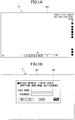
- FIGS. 1A, 1B , and 1C illustrate a comparative example of a sign-in operation method when a user signs in a handwriting input apparatus 2.
- FIG. 1A illustrates the operation screen 101 of the display.
- FIG. 1B illustrates a sign-in screen 102.
- FIG. 1C illustrates an enlarged view of a sign-in screen 102 and a soft keyboard 105.
- the sign-in screen 102 includes a user name entry field 103 and a password entry field 104. If the user name and password combination entered by a user are registered in the handwriting input apparatus 2, the handwriting input apparatus 2 can be used in a state where the authentication is successful and the user identified.
- a pen is an accessory of the handwriting input apparatus 2. Characters, numbers, symbols, alphabets (hereinafter, simply referred to as "characters, etc.”) and the like can be handwritten using the pen. However, at a time of signing in, the user needs to depress the user name entry field 103 and the password entry field 104 by operating the soft keyboard 105 displayed on the operation screen 101.
- the soft keyboard 105 is an input device that can easily hit the keys with both hands facing downward, and is not designed to make it easier to depress each key of the soft keyboard 105 displayed on the operation screen 101 with the pen. That is, the soft keyboard 105 is merely an imitation of the actual keyboard so as to enable the user to conduct a key input even in a device without a keyboard.
- the user can sign in using the IC card as illustrated in FIG. 1C .
- the user can only sign in by depressing a "Use IC Card" button 106 and holding the IC card down to the IC card reader. If a company has already introduced an IC card, it will be possible to sign in using the IC card simply by installing an IC card reader. However, because the IC card holds data that differ from company to company, introducing a new IC card at a company that has introduced a telework system will cost a great amount of money.
- the handwriting input apparatus 2 it is only necessary to use the fact that the characters or the like can be handwritten and sign in by handwriting with the pen, but it is necessary to perform extra operations such as having the user display a special frame for handwriting to sign in. In other words, the user could not handwrite without distinguishing between inputting characters etc. and inputting handwriting signatures.
- the handwriting input apparatus 2 authenticates the user using the user name or the like written indifferently from the input of a character or the like.
- Stroke data for users to sign in, such as user names, are called handwriting signature data.
- the user can sign in by handwriting the user name, without needing any operation to sign in, as in the case of handwriting.
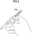
- FIGS. 2A and 2B are a diagram illustrating a schematic diagram of a signing in to the handwriting input apparatus 2 according to this embodiment.
- FIG. 2A illustrates the operation screen 101.
- the user name is handwritten on the operation screen 101. Similar to a case where the handwriting of an arbitrary character, the user name is handwritten, and there is no need to enter an issue indicating a sign-in operation is to be done or display a sign-in screen.
- Handwriting signature data are previously registered in the handwriting input apparatus 2.
- FIG. 2B illustrates an example of an operation guide 500.
- the handwriting input apparatus 2 displays an operation guide 500 below a handwriting object 504.
- the user name being the Japanese character corresponding to "Suzuki" is the handwriting object 504.
- one or more of the selectable candidates 530 are displayed in the operation guide 500.
- an operation command 512 an example of a display component
- a character string candidate 539 (handwriting recognition character string/language character string candidate, conversion string candidate, and character string/prediction conversion candidate, described later) are displayed in the selectable candidate 530.
- the character string candidate 539 four candidates are listed from up to down. The first one is Japanese Hiragana character string pronounced "suzuki" indicating the surname. The second one is Japanese Katakana character string pronounced "suzuki” indicating the surname. The third one is Japanese Kanji character string pronounced "suzuki” indicating the surname.
- the fourth one is Japanese Kanji character string pronounced "suzuki tarou" indicating the full name".
- the operation command 512 is an operation command for "signing in by handwriting” and is displayed upon successful authentication of the user's handwriting stroke data of the Japanese character corresponding to "Suzuki (translated from Japanese into English)" in the handwriting object 504 conforming to previously registered handwriting signature data. Said differently, it is displayed when the user authentication is successful.
- the user depresses the operation command 512 with a pen 2500 or the like, the user can sign in to the handwriting input apparatus 2. If user authentication is unsuccessful, the result of the recognition of the handwriting object 504 is displayed.
- various other operation commands are provided in the operation command 512.
- the corresponding operation commands are displayed when the converted text data from the handwriting stroke data partly coincide (coincide in part or in whole) with the character string for calling the previously registered operation command. That is, the user may invoke an operation command 512 for signing in by handwriting in the same manner as when calling other operation commands.
- the handwriting input apparatus 2 can be handwritten by the user without distinguishing between an input of characters or the like and an input of a handwriting sign, and can be handwritten by the user without distinguishing between various operation commands and the operation command 512 for signing in.
- the handwriting input apparatus 2 does not use a soft keyboard on the screen, does not add special hardware such as an IC card, and is capable of user authentication by only handwriting intuitively by a user.
- the input unit may be a unit that can be handwritten on a touch panel.
- An example includes a pen, a human finger, and hand, and rod-like member.
- eye-gaze tracking may be possible.
- Stroke data are freely handwritten lines.
- the stroke data have a set of successive points and may be interpolated as appropriate.
- An operation command is a command that instructs the execution of a specific process prepared to operate the handwriting input apparatus 2.
- an editing system, the modification system, the input/output system, and the operation commands in the pen state are exemplified.
- all commands that operate the handwriting input apparatus 2, such as reversed screen, page switching, and setting of the operation mode, are targeted.
- Handwriting signature data are stroke data for signing in by handwriting. As long as the stroke data are registered in the handwriting signature data storage unit, the stroke data are not limited to the user name.
- sign-in means an input of information indicating an identity of a person into a computer to request for a connection or start of use. If the input information coincides with the identity saved on the computer, the computer is enabled to be used based on predetermined authorization.
- the sign-in is also called login or logon.
- the display component for accepting the sign-in may be a soft key displayed for accepting the sign-in, and may be not limited to an operation command, but may be an icon, a button, or the like.
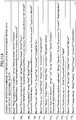
- FIG. 3 illustrates an example of a perspective view of a pen 2500.
- the pen 2500 illustrated in FIG. 3 is multifunctional, for example.
- the pen 2500 which has a built-in power supply and can send instructions to the handwriting input apparatus 2, is called an active pen (a pen without a power supply is called a passive pen).
- the pen 2500 of FIG. 3 has one physical switch on the tip of the pen, one on the butt of the pen, and two on the side of the pen.
- the tip of the pen is for writing, the butt of the pen is for deleting, and the side of the pen is for assigning user functions.
- the pen has a non-volatile memory and saves a pen ID that does not duplicate that of another pen.
- the pen with the switch mainly refers to an active pen.
- a passive pen without a built-in power supply using an electromagnetic induction mode can generate power only with a LC circuit. Therefore, not only the active pen but also the passive pen with the electromagnetic induction mode are applicable.
- a pen with an optical, infrared, or capacitance mode switch other than an electromagnetic induction mode switch is the active pen.
- the hardware configuration of the pen 2500 is the same as that in an ordinary control method including a communication function and a microcomputer.
- the pen 2500 may be an electromagnetic induction type, an active electrostatic coupling type, or the like. It may also have functions such as a pencil pressure detection, tilt detection, and hover function (displaying a cursor before the pen touches).
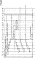
- FIGS. 4A, 4B, 4C, and 4D An overall configuration of the handwriting input apparatus 2 according to this embodiment will be described with reference to FIGS. 4A, 4B, 4C, and 4D.
- FIG. 4A to 4C are diagrams illustrating an overall configuration of the handwriting input apparatus 2.
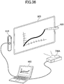
- FIG. 4A illustrates the handwriting input apparatus 2 used as an electronic blackboard having a horizontal length suspended on a wall.
- a display 220 as an example of a display device is installed on the handwriting input apparatus 2.
- the user U may manually write characters or the like on the display 220 (also referred to as input or drawing) using the pen 2500.
- FIG. 4B illustrates a handwriting input apparatus 2 used as a vertically-lengthwise electronic blackboard suspended in a wall.
- FIG. 4C illustrates a handwriting input apparatus 2 positioned flat on a desk 230. Because the handwriting input apparatus 2 is about 1 cm thick, it is not necessary to adjust the height of the desk even if it is placed flat on an ordinary desk. It can also be easily moved.
- the handwriting input apparatus 2 has an information processing device or computer configuration as illustrated.
- FIG. 5 is an example of a hardware configuration diagram of the handwriting input apparatus 2.
- the handwriting input apparatus 2 includes a CPU (Central Processing Unit) 201, ROM (Read Only Memory) 202, RAM (Random Access Memory) 203, and SSD (Solid State Drive) 204.
- CPU Central Processing Unit
- ROM Read Only Memory
- RAM Random Access Memory
- SSD Solid State Drive
- the CPU 201 controls the operation of the entire handwriting input apparatus 2.
- the ROM 202 saves programs used to drive the CPU 201 and an IPL (Initial Program Loader).
- the RAM 203 is used as a work area of the CPU 201.
- the SSD 204 saves various data such as a program for the handwriting input apparatus 2.
- the handwriting input apparatus 2 includes a display controller 213, a touch sensor controller 215, a touch sensor 216, a display 220, a power switch 227, a tilt sensor 217, a serial interface 218, a speaker 219, a microphone 221, a wireless communication device 222, an infrared I/F 223, a power supply control circuit 224, an AC adapter 225, and a battery 226.
- the display controller 213 controls and manages the screen display to output an output image to the display 220 or the like.
- the touch sensor 216 detects that the pen 2500 or user's hand or the like (the pen or user's hand works as an input unit) is in contact with the display 220.
- the touch sensor 216 also receives a pen ID.
- the touch sensor controller 215 controls processing of the touch sensor 216.
- the touch sensor 216 provides an input and detection of coordinates.
- a method for detecting the input and coordinates of this coordinate is, for example, a method in which two light emitting and receiving devices located at the upper and lower ends of the display 220 emit a plurality of infrared rays parallel to the display 220 and are reflected by a reflecting member provided around the display 220 to receive light returning on the same optical path as the light emitted by the light receiving element.
- the touch sensor 216 outputs the position information of infrared rays emitted by the two light emitting and receiving devices blocked by an object to the touch sensor controller 215, and the touch sensor controller 215 specifies the coordinate position that is the contact position of the object.
- the touch sensor controller 215 also includes a communication unit 215a that can communicate wirelessly with the pen 2500.
- a commercially available pen may be used when communicating in a standard such as Bluetooth ("Bluetooth" is a registered trademark).
- Bluetooth is a registered trademark.
- the user can communicate with the handwriting input apparatus 2 without performing connection setting that causes the pen 2500 to communicate with the handwriting input apparatus 2.
- the power switch 227 is a switch for switching the power of the handwriting input apparatus 2 ON/OFF.
- the tilt sensor 217 is a sensor that detects the tilt angle of the handwriting input apparatus 2. Mainly, the handwriting input apparatus 2 is used to detect whether the handwriting input apparatus 2 is used in the installation state of FIG. 4A, FIG. 4B, or FIG. 4C , and the thickness of the letters or the like can be automatically changed depending on the installation state.
- the serial interface 218 is a communication interface with an external device such as a USB.
- the serial interface 218 is used for input of information from external sources.
- the speaker 219 is used for audio output and the microphone 221 is used for audio input.
- the wireless communication device 222 communicates with a terminal carried by the user and relays, for example, a connection to the Internet.
- the wireless communication device 222 communicates via Wi-Fi, Bluetooth ("Bluetooth” is a registered trademark), or the like, but a communication standard is not specifically required.
- the wireless communication device 222 forms an access point and can be connected to the access point when the user sets the SSID (Service Set Identifier) and the password to the terminal that the user carries.
- SSID Service Set Identifier
- the wireless communication device 222 is preferably provided with two access points as follows.
- the access point a is for external users, and these users cannot access the internal network, but can use the Internet.
- the access point b is for internal users, and these users can use the internal network and the Internet.
- the infrared I/F 223 detects the adjacent handwriting input apparatus 2.
- the adjacent handwriting input apparatus 2 can be detected using the rectilinear propagation of the infrared ray.
- the infrared I/F 223 is preferably provided one by one on each side, and it is possible to detect which direction of another handwriting input apparatus 2 is disposed with respect to the handwriting input apparatus 2.
- the neighboring handwriting input apparatus 2 can display handwriting information (handwriting information on another page with the size of one display 220 being one page) that has been handwritten in the past.
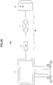
- the power supply control circuit 224 controls the AC adapter 225 and the battery 226 that is a power source for the handwriting input apparatus 2.
- the AC adapter 225 converts the alternating current shared by the commercial power supply to DC.
- the display 220 consumes little or no power to maintain the image after it has been rendered, so that it can also be driven by the battery 226.
- the handwriting input apparatus 2 for an application such as digital signature even in a place where it is difficult to connect a power source, such as an outdoor place.
- the handwriting input apparatus 2 includes a bus line 210.
- the bus line 210 is an address bus, a data bus, or the like for electrically connecting components such as the CPU 201 illustrated in FIG. 5 .
- the touch sensor 216 is not limited to an optical type.
- Various detection units may be used, such as a touch panel of an electrostatic capacitance type in which a contact position is specified by sensing a change in capacitance, a touch panel of a resistive film type in which a contact position is specified by a voltage change of two opposing resistive films, and an electromagnetic induction type in which an electromagnetic induction generated when a contact object contacts a display unit is detected and the contact position is specified.
- the touch sensor 216 may be of a method that does not require an electronic pen to detect the presence or absence of a touch at the tip end. In this case, a fingertip and pen-shaped bar can be used for a touch operation.
- the pen 2500 needs not be of an elongated pen type.
- FIG. 6A is an example of a functional block diagram illustrating functions of the handwriting input apparatus 2 in a block shape.
- the handwriting input apparatus 2 includes a handwriting input unit 21, a display unit 22, a handwriting input display control unit 23, a candidate display timer control unit 24, a handwriting input storage unit 25, a handwriting recognition control unit 26, a handwriting recognition dictionary unit 27, a character string conversion control unit 28, a character string conversion dictionary unit 29, a prediction conversion control unit 30, a prediction conversion dictionary unit 31, an operation command recognition control unit 32, an operation command definition unit 33, a pen ID control data storage unit 36, a handwriting signature authentication control unit 38, and a handwriting signature data storage unit 39.
- Each function of the handwriting input apparatus 2 is a function or unit implemented in which one of the components illustrated in FIG. 5 is operated by instructions from the CPU 201 according to a program deployed from the SSD 204 to the RAM 203.
- the handwriting input unit 21 is implemented by a touch sensor 216 or the like and receives handwriting input from a user and receives a pen ID.
- the handwriting input unit 21 converts the user's pen input d1 into pen operation data d2 (pen-up, pen-down, or pen-coordinate data) with the pen ID and transmits the converted data to the handwriting input display control unit 23.
- the pen coordinate data are transmitted periodically as discrete values, and the coordinates between discrete values are computed so as to be interpolated.
- the display unit 22 is implemented by the display 220 or the like to display a handwriting object or an operation menu.
- the display unit 22 converts the drawing data d3 written in the video memory by the handwriting input display control unit 23 into data corresponding to the characteristics of the display 220 and transmits the converted data to the display 220.
- the handwriting input display control unit 23 performs an overall control of handwriting input and display.
- the handwriting input display control unit 23 processes the pen operation data d2 from the handwriting input unit 21 and displays it by transmitting it to the display unit 22.
- the processing of the pen operation data d2 and the display of strokes will be described in detail with respect to FIGS. 28 to 34 , which will be described later.
- the candidate display timer control unit 24 is a display control timer of a selectable candidate. A timing for starting the display of the selectable candidate and a timing for deleting the display of the selectable candidate are generated timing by starting or stopping the timer.
- the selectable candidate is handwriting recognition character string/language character string candidates, conversion string candidates, character string/prediction conversion candidates, and operation command candidates selectably displayed in the operation guide described later.
- the candidate display timer control unit 24 receives the timer start request d4 (or the timer stop request may be) from the handwriting input display control unit 23 and transmits the timeout event d5 to the handwriting input display control unit 23.
- the handwriting input storage unit 25 has a storage function for storing user data (handwriting object/character string object).
- the handwriting input storage unit 25 receives the user data d6-1 from the handwriting input display control unit 23 and saves the data in the handwriting input storage unit 25.
- the handwriting input storage unit 25 receives the acquisition request d6-2 from the handwriting input display control unit 23 and transmits the user data d7 saved in the handwriting input storage unit 25.
- the handwriting input storage unit 25 transmits the position information d36 of the definitive object to the operation command recognition control unit 32.
- the handwriting recognition control unit 26 is an identification engine for performing online handwriting recognition. Unlike the ordinary OCR (Optical Character Reader), in parallel with the user's pen operation, characters (not only in Japanese but also in English and other multilingual languages), numbers, symbols (%, $, &, etc.), and graphics (lines, circles, triangles, etc.) are recognized. Various algorithms have been devised for recognizing methods, but in this embodiment details are omitted as well known techniques are available.
- the handwriting recognition control unit 26 receives the pen operation data d8-1 from the handwriting input display control unit 23 and performs handwriting recognition to hold the candidate handwriting recognition character string.
- the handwriting recognition control unit 26 holds the language character string candidate converted from the handwriting recognition character string candidate d12 using the handwriting recognition dictionary unit 27. Meanwhile, when the acquisition request d8-2 is received from the handwriting input display control unit 23, the handwriting recognition control unit 26 transmits the held handwriting recognition character string candidate and the language character string candidate d9 to the handwriting input display control unit 23.
- the handwriting recognition dictionary unit 27 is the dictionary data for the language conversion of the handwriting recognition.
- the handwriting recognition dictionary unit 27 receives the handwriting recognition character string candidate d12 from the handwriting recognition control unit 26, converts the handwriting recognition character string candidate into a language character string candidate d13 that is linguistically fixed, and transmits the conversion to the handwriting recognition control unit 26.
- Hiragana is converted into Kanji or katakana.
- the character string conversion control unit 28 controls the conversion of the conversion character string candidate into a character string.
- a conversion string is a character string that is likely to be generated including a handwriting recognition string or a language string.
- the character string conversion control unit 28 receives the handwriting recognition character string and the language character string candidate d11 from the handwriting recognition control unit 26, converts them into conversion character string candidates using the character string conversion dictionary unit 29, and holds them.
- the acquisition request d14 is received from the handwriting input display control unit 23
- the holding conversion character string candidate d15 is transmitted to the handwriting input display control unit 23.
- the character string conversion dictionary unit 29 is dictionary data for character string conversion.
- the character string conversion dictionary unit 29 receives the handwriting recognition character string and the language character string candidate d17 from the character string conversion control unit 28 and transmits the conversion character string candidate d18 to the character string conversion control unit 28.
- the prediction conversion control unit 30 receives the handwriting recognition character string and the language character string candidate d10 from the handwriting recognition control unit 26, and receives the conversion character string candidate d16 from the character string conversion control unit 28.
- the prediction conversion control unit 30 converts the handwriting recognition character string, the language character string candidate, and the conversion character string candidate to a prediction character string candidate using the prediction conversion dictionary unit 31.
- the prediction character string candidate is a character string that is likely to be generated including a handwriting recognition string, a language string or a conversion string.
- the prediction conversion dictionary unit 31 is the dictionary data for the prediction conversion.
- the prediction conversion dictionary unit 31 receives the handwriting recognition character string, the language character string candidate, and the conversion character string candidate d21 from the prediction conversion control unit 30, and transmits the prediction character string candidate d22 to the prediction conversion control unit 30.
- the operation command recognition control unit 32 receives the handwriting recognition character string and the language character string candidate d30 from the handwriting recognition control unit 26 and receives the conversion character string candidate d28 from the character string conversion control unit 28.
- the operation command recognition control unit 32 receives the prediction string candidate d29 from the prediction conversion control unit 30.
- the operation command recognition control unit 32 transmits the operation command conversion request d26 to the operation command definition unit 33 for the handwriting recognition character string, the language character string candidate, the conversion character string candidate, and the prediction character string candidate, respectively, and receives the operation command candidate d27 from the operation command definition unit 33.
- the operation command recognition and control unit 32 holds the candidate d27 of the operation command.
- the operation command definition unit 33 transmits the candidate d27 of the operation command to the operation command recognition control unit 32.
- the operation command recognition control unit 32 receives the pen operation data d24-1 from the handwriting input display control unit 23.
- the operation command recognition control unit 32 transmits the position information acquisition request d23 of the definitive object input in the past to the handwriting input storage unit 25.
- the operation command recognition control unit 32 holds the definitive object designated by the pen operation data as a selection object (including position information).
- the operation command recognition control unit 32 specifies the selection object that satisfies the position and predetermined criteria of the pen operation data d24-1.
- the pen ID control data storage unit 36 holds the pen ID control data (may be referred to as a storage unit). Before the handwriting input display control unit 23 transmits the display data to the display unit 22, the pen ID control data storage unit 36 transmits the pen ID control data d41 to the handwriting input display control unit 23. The handwriting input display control unit 23 draws display data under operation conditions saved in association with the pen ID. Further, before the handwriting recognition control unit 26 executes the handwriting recognition, the pen ID control data storage unit 36 transmits the angle information d44 of the pen ID control data to the handwriting recognition control unit 26, and the handwriting recognition control unit 26 rotates the stroke with the angle information saved in association with the pen ID to execute the handwriting recognition.
- the handwriting recognition control unit 26 After the handwriting recognition control unit 26 recognizes a straight line for setting the angle information when the user manually writes characters or the like, the handwriting recognition control unit 26 transmits the angle information d43 of the pen ID control data to the pen ID control data storage unit 36 to save the angle information d43 corresponding to the pen ID.
- the handwriting input display control unit 23 After the operation command for setting the angle information is executed by the handwriting input display control unit 23, the handwriting input display control unit 23 transmits the pen ID control data d42 to the pen ID control data storage unit 36 and saves the execution result of the operation command (the angle information set by the user) corresponding to the pen ID. Thereafter, the stroke of the pen ID is rotated with the set angle information, and handwriting recognition is performed.
- the handwriting recognition control unit 26 transmits the stroke data d49 rotated clockwise by the angle information of the pen ID control data to the handwriting signature authentication control unit 38. This allows authentication of the handwriting signature regardless of the user's position (in which direction it is handwritten to the handwriting input apparatus 2).
- the handwriting signature data storage unit 39 holds the handwriting signature data.
- the handwriting signature data storage unit 39 receives the handwriting signature data acquisition request d45 from the handwriting signature authentication control unit 38, the handwriting signature data storage unit 39 transmits the handwriting signature data d46 to the handwriting signature authentication control unit 38.
- the format of the handwriting signature data depends on the algorithm for handwriting signature authentication in the handwriting signature authentication control unit 38.
- the data of the handwriting signature data storage unit 39 will be described with reference to FIG. 14 .
- the handwriting signature authentication control unit 38 When receiving the stroke data d49 rotating clockwise from the handwriting recognition control unit 26, the handwriting signature authentication control unit 38 transmits the handwriting signature data acquisition request d45 to the handwriting signature data storage unit 39 and the handwriting signature data storage unit 39 transmits the handwriting signature data d46 to the handwriting signature authentication control unit 38.
- the handwriting signature authentication control unit 38 authenticates the user based on the handwriting signature data.
- the various algorithms have been devised for the user authentication based on the handwriting signature data, but in this embodiment, techniques that can be recognized at a recognition rate that does not hinder practical use are used. For example, a feature vector including elements such as a coordinate, brushing pressure, a time for writing a stroke and so on constituting the handwriting signature data are created, and the elements are weighted, and then the feature vector including the registered signature data are compared with the feature vector of the user's handwriting name or the like at the time of signing in are compared. When a coincidence degree is greater than or equal to the threshold value, it is determined as successful authentication. When it is lower than the threshold value, it is determined
- the handwriting signature authentication control unit 38 holds the authentication result of the handwriting signature that is the result of the comparison between the stroke data d49 and the handwriting signature data d46, and transmits the authentication result d47 of the held handwriting signature to the handwriting input display control unit 23 when the acquisition request d48 is received from the handwriting input display control unit 23.
- the authentication result of the handwriting signature includes whether the stroke data d49 and the handwriting signature data d46 are considered to coincide with and the Signature Id described later, which is associated with the coinciding handwriting signature data d46, if the stroke data d49 and the handwriting signature data d46 are considered to coincident.
- the handwriting recognition control unit 26 acquires the data d52 input to the handwriting signature registration form (a frame in which the handwriting signature data are input as described below) from the handwriting input storage unit 25 and transmits the handwriting signature data d50 of the data d52 to the handwriting signature authentication control unit 38.
- the handwriting signature authentication control unit 38 transmits the received handwriting signature data d50 to the handwriting signature data storage unit 39 to register.
- the handwriting recognition control unit 26 transmits the deletion request d51 of the handwriting signature registration form to the handwriting input storage unit 25 and deletes the handwriting signature registration from the handwriting input storage unit 25.
- the handwriting recognition control unit 26 acquires the data d53 input to the user-defined data change form from the handwriting input storage unit 25.
- the handwriting recognition control unit 26 transmits a change value d54 of the data d53 to the operation command definition unit 33 to change the user-defined data.
- the user-defined data will be described in FIG. 13 .
- the handwriting recognition control unit 26 When the handwriting recognition result of the handwriting recognition control unit 26 executes the instruction to cancel or the registration of the user-defined data change form, the handwriting recognition control unit 26 transmits the deletion request d55 of the user-defined data change form to the handwriting input storage unit 25 and deletes the user-defined data change form from the handwriting input storage unit 25.
- FIG. 6B is a functional block diagram illustrating the function of the pen 2500 in a block shape.
- the pen 2500 includes a pen event transmitting unit 41.
- the pen event transmitting unit 41 transmits the pen-up, pen-down, and pen-coordinate event data, to which a pen-ID is attached, to the handwriting input apparatus 2.
- FIG. 7 illustrates an example of defined control data.
- the example of FIG. 7 illustrates the control data for each control item.
- a selectable candidate display timer 401 defines the time until the selectable candidate is displayed (one example of the first time). This is because selectable candidates are not displayed during handwriting. In FIG. 7 , it is meant that the selectable candidate is displayed unless a pen-down occurs within a TimerValue of 500 ms from the pen-up.
- the selectable candidate display timer 401 is held by the candidate display timer control unit 24.
- the selectable candidate display timer 401 is used at the start of the selectable candidate display timer in step S18-2 of FIG. 30 , which will be described below.
- a selectable candidate deletion timer 402 defines the time until the displayed selectable candidate is deleted (one example of a second time). This is to delete the selectable candidate when the user does not select the selectable candidate.
- the selectable candidate deletion timer 402 is held by the candidate display timer control unit 24.
- the selectable candidate deletion timer 402 is used at the start of the selectable candidate display deletion timer in step S64 of FIG. 32 .
- the rectangular area 403 near the handwriting object defines a rectangular area considered to be near the handwriting object.
- the rectangular area 403 near the handwriting object expands the rectangular area of the handwriting object horizontally by 50% of the estimated character size, and vertically expands the vertical rectangular area by 80% of the estimated character size.
- the estimated character size is specified usiung a percentage (%). However, if the unit is "mm" or the like, the length can be fixed.
- the rectangular area 403 near the handwriting object is held by the handwriting input storage unit 25.
- the estimated character size 405 is used in step S10 of FIG. 29 to determine the overlap status of the rectangular area near the handwriting object and the stroke rectangular area.
- An estimated writing direction/character size determination condition 404 defines a constant for determining the writing direction and character size measurement direction.
- MinTime 1000 [ms] or more
- MinDiff 10 [mm] or more
- the horizontal distance is longer than the vertical distance
- the estimated writing direction is "horizontal" and the estimated character size is a vertical distance. If the horizontal distance is shorter than the vertical distance, it means that the estimated writing direction is "vertical" and the estimated character size is the horizontal distance.
- the estimation writing direction/character size determination condition 404 is held by the handwriting input storage unit 25.
- the estimation writing direction/character size determination condition 404 is used in the estimation writing direction acquisition in step S59 of FIG. 32 and in the character string object font acquisition in step S81 of FIG. 34 .
- Estimated character size 405 defines data for estimating the size of a character or the like. In the example of FIG. 7 , it is meant that the estimated character size determined by the estimation writing direction/character size determination condition 404 is compared to the smaller character 405a (hereinafter referred to as the minimum font size) of the estimated character size 405 and the larger character 405c (hereinafter referred to as the maximum font size). If the estimated character size is smaller than the minimum font size, the estimated character size is determined to be the minimum font size. If the estimated character size is larger than the maximum font size, the estimated character size is determined to be the maximum font size. Otherwise, the character size is determined to be medium character 405b. The estimated character size 405 is held by the handwriting input storage unit 25. The estimated character size 405 is used in the string object font acquisition in step S81 of FIG. 34 .
- the handwriting input storage unit 25 uses the font of the closest size when comparing the estimated character size determined by the estimation writing direction/character size determination condition 404 with the FontSize of the estimated character size 405. For example, when the estimated character size is 25 [mm] (FontSize of smaller characters) or less, “smaller character” is used. When the estimated character size is 25 mm or more but 50 mm (FontSize of middle character) or less, “medium character” is used. When the estimated character size is greater than 100 mm (FontSize of larger characters), the "larger character” is used.
- a straddle line determination condition 406 defines data used to determine whether multiple objects have been selected.
- the operation command recognition control unit 32 holds the straddle line determination condition 406.
- the straddle line determination condition 406 is used in determiinig the selection object in step S50 of FIG. 31 .
- a surrounding line determination condition 407 defines the data used to determine whether an object is an enclosing line (a surrounding line).
- the surrounding line determination condition 407 is held by the operation command recognition control unit 32.
- the surrounding line determination condition 407 is used in a surrounding line determination of determining the selection object in step S50 of FIG. 31 .
- Both the straddle line determination condition 406 and the surrounding line determination condition 407 may be determined with priority. For example, when the straddle line determination condition 406 is relaxed (when it is made easier to select the straddle line) and the surrounding line determination condition 407 is strictly made (when it is set as a value for which only the surrounding line can be selected), the operation command recognition control unit 32 may give priority to the surrounding line determination condition 407.
- FIG. 8 is an example of the dictionary data of the handwriting recognition dictionary unit 27.
- FIG. 9 is an example of the dictionary data of the character string conversion dictionary unit 29.
- FIG. 10 is an example of the dictionary data of the prediction conversion dictionary unit 31. Incidentally, each of these dictionary data are used in steps S33 to S42 of FIG. 31 .
- the conversion result of the dictionary data of the handwriting recognition dictionary unit 27 of FIG. 8 is called a language character string candidate
- the conversion result of the dictionary data of the character string conversion dictionary unit 29 of FIG. 9 is called a conversion character string candidate
- the conversion result of the dictionary data of the prediction conversion dictionary unit 31 of FIG. 10 is called a prediction character string candidate.
- "Before conversion” for each dictionary data indicates the character string to search for the dictionary data
- "after conversion” indicates the character string after conversion corresponding to the character string to be searched
- "probability” indicates the probability selected by the user.
- the probability is calculated from the result of the user selecting each string in the past. Therefore, probability may be calculated for each user.
- Various algorithms have been devised to calculate the probability, but they may be calculated in an appropriate way, and the details will be omitted.
- a character string candidate from the estimated writing direction is displayed in a selected probability descending order.
- the handwritten Japanese Hiragana characters "gi (as translated from Japanese in "before conversion” of rows 654 to English)" indicate the Japanese Kanji character “gi (as translated from Japanese in “after conversion” in the upper one of the rows 654 to English “meeting")” with a probability of 0.55 and the Japanese Kanji character “gi (as translated from Japanese in "after conversion” in the lower one of the rows 654 to English “tech”)” with a probability of 0.45.
- the handwritten Japanese Hiragana character strings "gishi (as translated from Japanese in "before conversion” of the rows 655 to English)" indicate the Japanese Kanji character string “gishi (as translated from Japanese in “after conversion” in the upper one of the rows 655 to English “tech-nical qualification")” with a probability of 0.55 and the Japanese Kanji character string “gishi (as translated from Japanese in "after conversion” in the lower one of the rows 655 to English “tech-nical engineer”)” with a probability of 0.45.
- the Japanese character strings are in Japanese Hiragana. However, these character strings may be other than Japanese and Japanese Hiragana.
- the Japanese character strings are in Japanese Kanji or Katakana. However, these character strings may be other than Japanese, Japanese Kanji, and Japanese Katakana.
- the rows 655 and 656 indicate conversions from the Japanese Hiragana character strings to Japanese Kanji or Katakana character strings with the listed probabilities, as examples.
- the Japanese Kanji character string “gi (as translated from Japanese in “before conversion” in the upper one of rows 657 to English “meeting”)” is converted to Japanese Kanji character string “gi-jiroku” corresponding to "meeting minute” with a probability of 0.95.
- the Japanese Kanji character string “gi (as translated from Japanese in "before conversion” in the lower one of the rows 657 to English “tech”)” is converted to Japanese character string “gi-ryoushi” corresponding to "technical skill test” with a probability of 0.85.
- the rows 658, 659, and 660 indicate conversions from the Japanese Kanji or Hiragana character strings to Japanese Kanji character strings with the listed probabilities, as examples.
- the Japanese Kanji character string "gi-jiroku (as translated from Japanese in "before conversion” in the upper one of rows 661 to English “meeting minute”)” is converted to Japanese character string “gi-jirokunosoufusaki” corresponding to English "transmission destination of meeting minute” with a probability of 0.65.
- the Japanese Kanji character string “gi-ryoushi (as translated from Japanese in "before conversion” in the lower one of the rows 661 to English “technical skill test”)” is converted to Japanese character string “giryoushiwokessai” corresponding to "technical skill test is approved” with a probability of 0.85.
- the rows 661, 662, 663, and 664 indicate conversions from the Japanese Kanji character strings to Japanese Kanji, Hiragana, and/or Katakana character strings with the listed probabilities.
- All of the character strings before conversion are Japanese Kanji character strings, but a character string other than Kanji character string may be registered.
- All of the character strings after conversion are Japanese Kanji, Hiragana, and/or Katakana character strings, but a character string other than Japanese such as other languages like Chinese, German, Portuguese, and so on and Japanese Kanji, Hiragana, and/or Katakana character string may be registered.
- the dictionary data are language independent, and any character string may be registered before and after conversion.
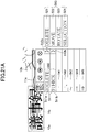
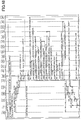
- FIGS. 11A and 11B illustrate an example of the operation command definition data and the system definition data held by the operation command definition unit 33.
- FIG. 11A illustrates an example of operation command definition data.
- the operation command definition data illustrated in FIG. 11A is an example of the operation command definition data when there is no selection object selected by a handwriting object, and all the operation commands that operate the handwriting input apparatus 2 are targeted.
- Each of the operation command definition data 701 to 716 illustrated in FIG. 11A have an operation command name (Name), a character string that partly coincides with the character string candidate (String), and an operation command string (Command) to be executed.
- Name Japanese character strings pronounced in Japanese "tegaki sain suru” translated in English as "handwriting sign in”.
- the operation command definition data 701 indicates that the name (Name) of the operation command is "Gi-jiroku tenpuretowo yomikomu” translated in English as “Read meeting minute template", the character string that partly coincides with the character string candidate is "meeting minute” or “template”, and the operation command string to be executed is "ReadFile https://%username%: %password%@server.com/templates/minute.pdf".
- “%...%” system definition data are included in the operation command string to be executed, and "%username%” and “%password%” may be replaced by system definition data 704 and 705, respectively.
- the final operation-command string is "ReadFile https://taro.tokkyo: x2PDHTyS@server.com/template/minute.pdf", indicating that the file "https://taro.tokkyo: x2PDHTyS@server.com/minute.pdf" is read (ReadFile).
- the operation command definition data 702 indicates that the name (Name) of the operation command is "Gi-jikoku forudani hozonnsuru” translated in English as “save in meeting minute folder” that the character string that partly coincides with the character string candidate is "minute” or “save”, and that the operation command string to be executed is "WriteFile https:/%username%:%password%@server.com/minute/%machinename%_ %yyyyy-mm-dd.pdf”. Similar to the operation command definition data 701, "%username%”, %password%”, and “%machinename%” in the operation command string are replaced by system definition data 704 to 706, respectively.
- “%yyyy-mm-dd%” is to be replaced by the current date. For example, if the current date is September 26, 2018, it will be replaced by "2018-09-26".
- the final operation command is "WriteFile https://taro.tokkyo: x2PDHTyS@server.com/mintes/%My-Machine_2018-09-26.pdf" and indicate that the minute are to be saved in the file "https://taro.tokkyo: x2PDHTyS@server.com/%minute/%My-Machine_2018-09-26.pdf" (WriteFile).
- the operation command definition data 703 indicates that the name of the operation command is "to be printed", the character string that partly coincides with the character string candidates is "print” or "printed”, and the operation command string to be executed is "PrintFile https:/%username%:%password%@server.com/print/%machiname%-%yyyy-mm-dd%.pdf".
- the final operation command to be executed is "PrintFile https://taro.tokkyo: x2PDHTyS@server.com/print/%My-Machine_2018-09-26.pdf", indicating that the file "https://taro.tokkyo: x2PDHTyS@server.com/print/%My-Machine_2018-09-26.pdf" is printed (PrintFile). That is, the file is sent to the server. The user allows the printer to communicate with the server, and the printer prints the contents of the file on the paper when the file is specified.
- the operation command definition data 701 to 703 can be identified from the character string candidate, the operation command can be displayed by a user by handwriting. If user authentication is successful, "%username%", %password%” or the like of the operation command definition data will be replaced in the user information, and thus the input and output of the file can be performed in association with the user.
- the handwriting input apparatus 2 replaces the predetermined "%username%", %password%" of the handwriting input apparatus 2. Accordingly, even without user authentication, the input and output of the file corresponding to the handwriting input apparatus 2 is enabled.
- the operation command definition data 709, 710, and 711 are operation commands that change the pen state.
- the pen state can also be referred to as a pen kind.
- the names ("Name") of the operation command definition data 709, 710, and 711 are “fine pen", “thick pen”, and “marker”, respectively.
- the character string (“String”) that coincides with the character string candidate is “fine”, “pen”, “thick”, “pen”, “marker”, or “pen”, respectively.
- the operation command string (“Command) is "ChangePen fine”, “ChangePen bold”, or “ChangePen marking".
- the operation command definition data 712 is an operation command for aligning the orientation of the text data in a constant direction.
- the operation command name of the operation command definition data 712 is "align the text direction", "orientation” or “direction”, and the operation command character string is "AlignTextDirection". Text data written by the user in a direction other than the vertical directions is so sparse in directions that it is difficult to read everything from one direction.
- the handwriting input apparatus 2 aligns character strings recognized to be handwritten in the same direction (for example, in the vertical directions). In this, the aligning means rotating the text data by angular information.
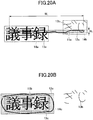
- the operation command definition data 713 indicates that the name of the operation command is "to register with a handwriting signature", the character string that partly coincides with the character string candidate is “signature” and “registration”, and the operation command string is "RegisterSignature”.
- a handwriting signature registration form is added to the handwriting input storage unit 25 and the handwriting signature registration form is displayed on the operation screen 101.
- An example of a handwriting signature registration form will be described later (see FIGS. 25A, 25B , and 25C ).
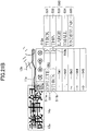
- the operation command definition data 714 indicate that the operation command name is "%signature%” and the operation command is "Signin” for a character string candidate and a character string at a partial position.
- "%signature%” is a reserved word for system definition data and represents the fact that the registered handwriting signature data and stroke data such as user name fit. That is, when fitted, an operation command 512 based on the operation command definition data 714 is displayed in the operation guide 500 (see FIGS. 2 and 26 ).
- the handwriting input apparatus 2 can use the user-defined data specified by this Accountld to be used by the handwriting input apparatus 2 (see FIG.16A ).
- the operation command definition data 715 indicate that the operation command name is "handwriting sign out", a character string that partly coincides with the character string candidate is "sign" or "out", and the operation command is "Signout”.
- Signout command is executed, Accountld is deleted from the pen ID control data of the pen 2500 that manipulates the handwriting signout. This eliminates the association between the pen ID and Accountld to enable any user to use the pen 2500.
- the operation command definition data 716 indicate that the name of the operation command "change setting", the character string that partly coincides with the character string candidate is “set” or “changed”, and the operation command is "ConfigSettings".
- the ConfigSettings command is executed, the user-defined data change form is added to the handwriting input storage unit 25 and the user-defined data change form is displayed on the operation screen 101.
- the user-defined data change form is described later (see FIGS. 27A and 27B ).
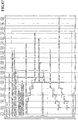
- FIG. 12 illustrates an example of the operation command definition data when there is a selection object selected by a handwriting object.
- the operation command definition data of FIG. 12 have an operation command name (Name), a group name (Group) as the operation command candidate, and an operation command string (Command) to be executed.
- the operation command definition data 707 and 708 are identified so that the user can manually write to display the operation command.
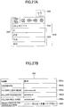
- FIG. 13 illustrates an example of user-defined data held by the operation command definition unit 33.
- the user-defined data in FIG. 13 is an example of the defined data for a single user.
- “Accountld” in user-defined data 717 is user identification information automatically assigned to each user;
- "AccountUsername” and “AccountPassword” are user names and passwords;
- “Signatureld” is identifying information of handwriting signature data automatically assigned at the time of handwriting signature data registration;
- “username”, "password” and “machinename” are character strings set in operation command definition data 701 to 703 instead of the system definition data 704 to 706, respectively. This allows execution of the operation command using the user-defined data.
- what is used at a time of executing the operation command is the character string of the user-defined data having Accountld associated with the pen ID of the pen 2500 based on an association among the pen ID, Accountld, and the pen ID control data (see FIG. 16A ).
- the character string of the system definition data is used when executing the operation command, even if the pen 2500 that the user has used for signing in is used.
- User-defined data 718 are the data used in a user-defined data change form.
- Name is the item name of AccountUsername, AccountPassword, username, password, or machinename of the user-defined data 717
- data are the change value of AccountUsername, AccountPassword, username, password, or machinename.
- the data of "Name” are "%AccountName%”
- Password is “%AccountPassword%”
- “Folder User Name” is "%username%”
- “Folder Password” is "%password”
- the data for "Folder File Name” is "%machinename", which respectively correspond to items of the user-defined data 717.
- FIG. 14 illustrates an example of handwriting signature data held by the handwriting signature data storage unit 39.
- the handwriting signature data include data representing the handwriting signature associated with Signatureld.
- Signatureld is identification information automatically assigned at the time of registering the handwriting signature data, and Data are calculated by the handwriting signature authentication algorithm of the handwriting signature authentication control unit 38 from the stroke data received from the handwriting signature authentication control unit 38.
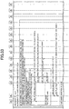
- FIG. 15 illustrates an example of the handwriting input storage data saved in the handwriting input storage unit 25.
- One raw in FIG. 15 represents a stroke.
- One handwriting input storage data have the following items: Datald, Type, Penld, Color, Width, Pattern, Angle, Accountld, StartPoint, StartTime, EndPoint, EndTime, Point, and Pressure.
- Datald is identification information of the stroke.
- Type is a type of the stroke. The type includes Stroke, Group, and Text.
- the type of the handwriting input storage data 801 and 802 is Stroke, and the type of the handwriting input storage data 803 is Group. Group means making a group of other strokes, and the handwriting input storage data whose type is Group designate the strokes to be the group.
- Penld, Color, Width, Pattern, Angle, and Accountld are pen ID control data described below. StartPoint is the start point coordinate of the stroke and StartTime is the start time of the stroke. EndPoint is the end point coordinate of the stroke and EndTime is the end time of the stroke.
- Point is the coordinate column from the start point to the end point
- Pressure is the brush pressure from the start point to the end point.
- the handwriting input storage data 804 and 805 are illustrated to be rotated clockwise by 180 degrees and 270 degrees, respectively, before handwriting recognition.
- FIG. 16A and 16B are a diagram for explaining the pen ID control data saved in the pen ID control data storage unit 36. Each row of FIG. 16A indicates one of the pen ID control data of one pen.
- FIG. 16B is a diagram illustrating angle information when a user handwrites with to the handwriting input apparatus 2. The angle information can be the angle in the direction in which the user is present, the angle in the direction in which the pen is used, or the angle related to the rotation of the character handwritten by the user.
- the angular information of each user is 45 degrees, 90 degrees, 135 degrees, 180 degrees, 225 degrees, 270 degrees, and 315 degrees counterclockwise.
- the user's angle information is the location of the user relative to the handwriting input apparatus 2 when the handwriting input apparatus 2 is positioned flat. That is, the information about the user's angle is the information about the location. Viewed from the handwriting input apparatus 2, it is possible to identify which direction the user is in.
- the direction viewed from the handwriting input apparatus 2 may be simulated to be a clock, and may be expressed as follows: 0 degrees: 6 o'clock direction; 45 degrees: 4 o'clock direction and 5 o'clock direction; 90 degrees: 3 o'clock direction; 135 degrees: 1 o'clock direction and 2 o'clock direction; 180 degrees: 12 o'clock direction; 225 degrees: 10 o'clock and 11 o'clock direction; 270 degrees: 9 o'clock direction; and 315 degrees: 7 o'clock direction and 8 o'clock direction.
- the angle information is not automatically determined by the user's position, and each user enters (specifies) the angle information.
- the resolution of the angular information that can be specified is only one example and may be smaller, such as 5 degrees to 30 degrees. However, if the character is rotated by about 45 degrees, the user may read them.
- the pen ID control data include Penld, Color, Width, Pattern, Angle, and Accountld.
- Penld is identification information saved inside the pen. Color is the stroke color set for this pen (the user can arbitrarily change it). Width is the width of the stroke set to this pen (the user can arbitrarily change it). Pattern is the line type of the stroke set to this pen (the user can arbitrarily change it). Angle is the angle information of the stroke set in this pen (the user can arbitrarily change it). In the example of FIG. 16A , the angle information for each pen is 0 degrees, 90 degrees, 180 degrees, and 270 degrees counterclockwise.
- Accountld is the identification information of the user. By associating the pen ID with Accountld, Accountld associated with the pen ID of the pen 2500 used by the user can be specified and the operation command can be executed using the user-defined data.
- Pen ID control data 901 are control data having a pen ID of 1.
- the pen ID control data without Accountld indicate a signed out state (not associated with the user).
- pen ID control data 902 are a pen ID of 2.
- the color is black.
- the thickness is 1 pixel.
- the pattern is solidly painted.
- the angle information is 90 degrees. Accountld is not present.
- the pen ID control data 903 have a pen ID of 3.
- the color is black. It is 10 pixels thick.
- the pattern is solid. Angle information is 180 degrees. Accountld is not present.
- the pen ID control data 904 are black in color. It is 10 pixels thick. The pattern is halftone dots. The angle information is 270 degrees. Accountld is not present.
- Step S5 acquisition of pen ID control data
- Step S20 storage of angle information of pen ID control data
- Step S21 acquisition of angle information of pen ID control data
- Step S60 acquisition of pen ID control data
- Step S88 storage of angle information of pen ID control data
- FIG. 17 is an example of an operation guide 500 and a selectable candidate 530 displayed by the operation guide.
- the user handwrites the handwriting object 504 (due to the timeout of the selectable candidate display timer) so that the operation guide 500 is displayed.
- the operation guide 500 includes an operation header 520, an operation command candidate 510, a handwriting recognition character string candidate 506, a conversion character string candidate 507, a character string/prediction conversion candidate 508, and a handwriting object rectangular area display 503.
- the selectable candidate 530 includes the operation command candidate 510, the handwriting recognition character string candidate 506, the conversion character string candidate 507, and the character string/prediction conversion candidate 508. This example includes a case where a language conversion character string may be displayed even though there is no language conversion character string.
- the selectable candidate 530, excluding the operation command candidate 510, is called the character string candidate 539.
- the operation header 520 has buttons 501, 509, 502, and 505.
- the button 501 accepts a switching operation between a prediction conversion and kana conversion.
- the handwriting input unit 21 receives the depressing and notifies the handwriting input display control unit 23 thereof, and the display unit 22 changes the display to the button 501 indicating "Kana”.
- the character string candidates 539 are arranged in a probability descending order of "kana conversion”.
- the buttons 502 perform a page operation on a candidate display.
- the candidate display page is 3 pages, and currently the first page is displayed.
- the button 505 receives deletion of the operation guide 500.
- the handwriting input unit 21 receives the depressing and notifies the handwriting input display control unit 23 of the depressing, and the display unit 22 deletes the display other than the handwriting object.
- the button 509 accepts collective display deletion.
- the handwriting input unit 21 receives the depressing and notifies the handwriting input display control unit 23 of the depressing.
- the display unit 22 includes a handwriting object and deletes all displays illustrated in FIG. 17 . The user can handwrite from the beginning.
- the handwriting object 504 is a Japanese Hiragana letter "Gi (as a Roman character of the Japanese Hiragana letter)" handwritten by the user.
- a handwriting object rectangular area display 503 surrounding the handwriting object 504 is displayed. The procedure for displaying is illustrated in the sequence diagrams of FIGS. 28 to 34 . In the example of FIG. 17 , the handwriting object rectangular area display 503 is displayed in a dotted frame.
- Each of the handwriting recognition character string candidate 506, the conversion character string candidate 507, and the character string/prediction conversion candidate 508 is arranged in probability descending order.
- the Japanese Hiragana letter corresponding to "Gi (as a Roman character of the Japanese Hiragana letter indicated in the handwriting recognition character string candidate 506 illustrated in FIG. 17 )" is a candidate for the recognition result.
- the Japanese Hiragana letter "Gi (as the Roman character of the Japanese Hiragana letter) is correctly recognized.
- the conversion character string candidate 507 is a conversion character string candidate converted from a language character string candidate.
- the Japanese Kanji character string "technical skill test” is an abbreviation for "technical skill test system”.
- the character string/prediction conversion candidate 508 is the prediction string candidate converted from the language character string candidate or the conversion character string candidate.
- Japanese character strings corresponding to "technical skill test is approved” and "transmission destination of meeting minute” are displayed in the character string/prediction conversion candidate 508.
- the operation command candidate 510 is a candidate of the operation command selected based on the operation command definition data 701 to 703 and 709 to 716 of FIG. 11A .
- each row initial letter 511 of "»" indicates that the subsequent character strings are an operation command.
- the operation command defined by the operation command definition data 701 is executed.
- the operation command defined by the operation command definition data 702 is executed.
- the operation command candidate is displayed only when the operation command definition data including the converted character string are found. Therefore, the operation command candidate is not always displayed.
- the user can select either the character string candidate or the operation command to be entered by the user.
- the display unit 22 displays the operation guide 500 including text data at a position corresponding to the position of the stroke data.
- the display unit 22 displays the operation guide 500 including text data at a position inside the screen based on the position of the stroke data.
- the position of the operation guide 500 is determined by the position of the stroke data.
- FIGS. 18A and 18B illustrate a relationship between a position of the operation guide and a position of a handwriting object rectangular area display.
- the width A and height H1 of the operation guide 500 are constant.
- the right end of the handwriting object rectangular area display 503 coincides with the right end of the operation guide 500.
- the width B of the handwriting object rectangular area display 503 is determined by the length of the handwriting object 504 written by the user.
- the coordinate (x0, y0) of the left upper corner P of the operation guide 500 is calculated as follows.
- the coordinate of the upper left corner Q of the handwriting object rectangular area display 503 are (x1, y1).
- the height of the handwriting object rectangular area display 503 is represented by H2.
- FIG. 18A illustrates the operation guide 500 below the handwriting object rectangular area display 503
- the operation guide 500 may be displayed above the handwriting object rectangular area display 503.
- FIG. 19 the operation guide 500 is displayed above the handwriting object rectangular area display 503.
- the calculation method of x1 is the same as that of FIGS. 18A.
- FIGS. 18A and 18B are diagrams illustrating a relationship between the position of the operation guide and the position of the handwriting object rectangular area display.
- the width A and height H1 of the operation guide 500 are constant.
- the right end of the handwriting object rectangular area display 503 coincides with the right end of the operation guide 500.
- the width B of the handwriting object rectangular area 503 is determined by the length of the handwriting object 504 written by the user.
- the coordinates (x0, y0) of the left upper corner P of the operation guide 500 are calculated as follows.
- the coordinates of the upper left corner Q of the handwriting object rectangular area display 503 are (x1, y1).
- the height of the handwriting object rectangular area display 503 is assumed to be H2.
- FIGS. 18A and 18B illustrate the operation guide 500 below the handwriting object rectangular area display 503, the operation guide 500 may be displayed above the handwriting object rectangular area display 503.
- FIG. 19 illustrates the operation guide 500 displayed above the handwriting object rectangular area display 503.
- the calculation method of x1 is the same as that of FIGS 18A and 18B , but the calculation method of y0 changes.
- y 0 y 1 ⁇ H 1
- the operation guide 500 may be displayed on the right side or the left side of the handwriting object rectangular area display 503. Also, if the user handwrites at the end of the display so that there is no display space in the operation guide 500, the operation guide 500 is displayed on the side where a display space is located. The calculation method of 0 is changed.
- the handwriting input apparatus 2 can designate a selection object by the user who selects a definitive object by hand.
- the selection object is subject to editing or modification.
- FIGS. 20A to 20D are examples of a diagram illustrating a designation example of a selection object.
- a black solid straight line is displayed in the handwriting object 11
- a grey shaded area 12 in the handwriting object a black straight line is displayed in the definitive object 13
- a dotted straight line is displayed in the rectangular area 14 of the selection object.
- a lower-case alphabet is appended to the symbol to distinguish between them.
- the straddle line determination condition 406 or the surrounding line determination condition 407 of the defined control data illustrated in FIG. 7 is used as a determination condition (whether a predetermined relationship exists) for determining a definite object as a selection object.
- FIG. 20A illustrates an example in which two definitive objects 13a and 13b in horizontal writing are specified by a user using a straddle line (handwriting object 11a).
- the length H1 of the shorter side and the length W1 of the shorter side of the rectangular area 12a satisfy the conditions of the straddle line determination condition 406 and the overlap rate with the definitive object 13a and 13b satisfies the conditions of the straddle line determination condition 406, both the Japanese Kanji character string corresponding to "meeting minute (pronounced in Japanese "Gi-ji-roku")" and the Japanese Hiragana character string corresponding to "Gi-ji (pronounced in Japanese "Gi-ji”)" of the definitive objects 13a and 13b are designated as the selection object.
- FIG. 20B illustrates an example in which the definitive object 13c in horizontal writing is designated by a surrounding line (handwriting object 11b).
- the definitive object 13c which is "meeting minute", in which the overlap ratio of the definitive object 13c and the handwriting object rectangular area 12c satisfies the conditions of the surrounding line determination condition 407, is designated as the selection object.
- FIG. 20C is an example in which a straddle line (handwriting object 11c) is designated by a plurality of definitive objects 13d and 13e written vertically.
- the length H1 of the short side and the length W1 of the long side of the handwriting object rectangular area 12d satisfy the conditions of the straddle line determination condition 406, and the overlap ratio of the two definitive object 13d and 13e, the Japanese Kanji character string corresponding to "meeting minute (pronounced in Japanese "Gi-ji-roku")" and the Japanese Hiragana character string corresponding to "Gi-ji (pronounced in Japanese "Gi-ji"), respectively, satisfies the conditions of the straddle line determination condition 406. Therefore, the definitive object 13d and 13e of both the "minute” and the "Gi-ji" are designated as the selection objects.
- FIG. 20D is an example in which the vertically written definite object 13f is designated by a surrounding line (handwriting object 11d).
- the definitive object 13f of the Japanese Kanji character string corresponding to "meeting minute” is designated as the selection object.
- FIGS. 21A and 21B illustrate a display example of an operation command candidate based on the operation command definition data when the handwriting object illustrated in FIG. 12 is present.
- FIG. 21A is an operation command candidate in the editing system
- FIG. 21B is an operation command candidate in the modification system.
- FIG. 21A illustrates an example in which a selection object is designated as a handwriting object 11a in FIG. 20A .
- the main menu 550 lists operation command candidates displayed after each row initial letter 511 of "»".
- the main menu 550 displays the last executed operation command name or the first operation command name in the operation command definition data.
- An initial letter 511a of "»" on the first row indicates the operation command of an editing system, which is a candidate for the editing operation command, and an initial letter 511b of "»" on the second row indicates the operation command of the modifying system.
- Each of row end letters ">" 512a and 512b indicates that there is a sub menu (an example of a sub menu button).
- the row end letter ">" 512a of the first row of the main menu 550 illustrates a sub menu (finally selected) for the operation command candidate in the editing system.
- the row end letter ">" 512b of the second row of the main menu 550 illustrates a sub menu for the operation command candidates of the modifying system.
- a sub menu 560 appears to the right.
- the sub menu 560 displays all the operation commands defined in the operation command definition data.
- the display example of FIG. 21A also illustrates the sub menu 560 corresponding to the row end letter ">" 512a when the main menu is displayed. It may be displayed by depressing the row end letter ">" 512a on the first row.
- the handwriting input display control unit 23 executes the command of the operation command definition data associated with the operation command name for the selection object. That is, “delete” when “delete” 521 is selected, “move” when “move” 522 is selected, “rotate” when “rotate” 523 is selected, and “select” when “selection” 524 is selected.
- Character string candidates other than the operation command candidates "-" 541, "-,” 542, “-” 543, “ ⁇ ” 544, and double-lined arrow like " ⁇ ” 545 are the recognition results of the straddle line (the handwriting object 11a). If the user intends to enter the character string instead of the operation command, the character string candidates can be selected.
- the sub menu 560 is displayed by clicking ">" 512b in the second row.
- the main menu 550 and the sub menu 560 are also displayed in the display example illustrated in FIG. 21B .
- the handwriting input display control unit 23 executes "thick” when "thick” 531 is selected, "thin” when “thin” 532 is selected, and "large” 533 is selected, “small” when “small” 534 is selected, and "underline” when “underline” 535 is selected for the selection object.
- preset values are defined separately: how thicken is to be made when "thick" 531 is selected, how thin is to be made when “thin” 532 is selected, how large is to be made when “large” 533 is selected, how small is to be made when “small” 534 is selected, a line type when "underline 535" is selected, and the like.
- the selection menu may be opened to allow the user to adjust.
- the handwriting input display control unit 23 thickens the lines forming the definitive objects 13a and 13b of the Japanese character strings corresponding to "meeting minute” and “meeting".
- the line forming the Japanese character strings corresponding to "meeting minute” and “meeting” can be narrowed by the handwriting input display control unit 23.
- the handwriting input display control unit 23 can enlarge the Japanese character strings, and when the "small” 534 is depressed with the pen, the handwriting input display control unit 23 can reduce the Japanese character strings.
- the "underline” 535 is depressed with the pen, the handwriting input display control unit 23 can add an underline to the Japanese character strings.
- FIG. 22A and 22B illustrate a display example of an operation command candidate based on the operation command definition data when the handwriting object illustrated in FIG. 12 is present.
- the difference of FIGS. 22A and 22B from FIG. 21A and 21B is that a selection object is designated in the handwriting object 11b (surrounding line) illustrated in FIG. 20B .
- the handwriting input display control unit 23 displays the operation command candidate on the display unit 22.
- the operation command definition data as illustrated in FIG. 12 are associated with the recognized handwriting object (-, O, etc.).
- FIGS. 23A, 23B , and 23C are an example of a diagram illustrating an input method of angle information.
- FIGS. 23A, 23B , and 23C illustrate a case in which the user present in the 3 o'clock direction of the handwriting input apparatus 2 inputs the angle information. Because handwriting characters from the 3 o'clock direction are correctly recognized when they are rotated 90 degrees clockwise, angle information of 90 degrees is entered.
- FIG. 23A illustrates a state in which the operation guide 500 is displayed because a user present in the 3 o'clock direction of the handwriting input apparatus 2 handwrites the Japanese character "Gi" corresponding to English character “meeting” in a state in which the angle information of the pen ID control data is 0 degrees (the initial value). Because the handwriting input apparatus 2 recognizes the handwritten Japanese Hiragana character "Gi (pronounced in Japanese "Gi")" from the direction of 3 o'clock while the angle information is 0 degrees, a selectable candidate 530 that is different from the expected one is displayed.
- FIG. 23B illustrates an example of this straight line 571.
- the direction of the end point of the straight line 571 is angular information. Therefore, the angle information entered by the user in FIG. 23B is 90 degrees.
- a method for detecting the straight line for example, is used in which the coordinates from the start point S to the end point E are converted into a straight line by the least-square method, and the obtained correlation coefficient is compared with the threshold value to determine whether the straight line is used.
- the handwriting input apparatus 2 deletes the operation guide 500.
- the handwriting input apparatus 2 searches for and determines the closest value of the above angle ⁇ from 45 degrees, 90 degrees, 135 degrees, 180 degrees, 215 degrees, 270 degrees, 315 degrees, and 360 degrees, and determines this as the angle information.
- the angle ⁇ itself may be used as the angle information.
- the angle of the pen ID control data is set to the determined angle information.
- the pen event transmitting unit 41 of the pen 2500 transmits the pen ID to the handwriting input apparatus 2 when the pen tip is depressed for handwriting or the like. Therefore, the handwriting input apparatus 2 can associate the pen ID control data with the angle information.
- the operation guide 500 can be subjected to handwriting of the straight line and inputting of the angle information. Accordingly, when the user handwrites the straight line in other than the operation guide 500, the straight line may be recognized as "1", "-", or the like, and when the straight line is handwritten by the operation guide 500, the angle information can be input. That is, the handwriting recognition control unit 26 detects the straight line from a predetermined range and converts the handwriting stroke data out of the predetermined range into text data.
- the handwriting object (stroke data) is internally rotated in a clockwise direction by 90 degrees to be subjected to handwriting recognition, and the operation guide 500 is rotated in a counterclockwise direction by 90 degrees so as to be displayed.
- FIG. 24 is an example of a diagram illustrating another input method of the angle information.
- the user is present in the 3 o'clock direction of the handwriting input apparatus 2.
- the user present in the 3 o'clock direction of the handwriting input apparatus 2 handwrites the Japanese Hiragana letter corresponding to "gi (pronounced in Japanese "gi")" with the angle information being 0 degrees (the initial value), so that the operation guide 500 and the selectable candidate 530 are displayed.
- the operation guide 500 of FIG. 24 includes a rotation operation button 519 in the operation header 520.
- the rotation operation button 519 is a button that adds 90 degrees of the angle information of the pen ID control data, and the added angle information is divided by 360 degrees each time the user depresses it down by the pen 2500 to obtain a remainder. This remainder becomes the angle information.
- the angle to be added under one pressing of the rotation operation button 519 may be set to 45 degrees.
- FIGS. 25A, 25B , and 25C are a diagram illustrating a method of registering a handwriting signature data.
- FIG. 25A is an example of a selectable candidate 530 displayed when the user handwrites the Japanese Katakana character string corresponding to the English character string of "signature (pronounced in Japanese "Sain)".
- the handwriting signature registration form 561 illustrated in FIG. 25B is added to the handwriting input storage unit 25 and is displayed on the operation screen 101.
- the operation guide 500 of FIG. 25A is deleted and a handwriting signature registration form 561 is displayed in the same location as the operation guide 500.
- the handwriting signature registration form 561 has a name entry field 561a, signature entry fields 561b to 561d, and a registration confirmation field 561e from top to down.
- the user enters a name text in the name entry field 561a, a first handwriting signature, a second handwriting signature, and a third handwriting signature in the signature entry fields 561b to 561d, and a check mark or cancellation mark in the registration confirmation field 561e.
- the text of the name is the display name of this user and is converted to text data.
- Three handwriting signatures are entered because the feature amount is registered on the assumption that the signature differs and does not completely coincide each time the user writes it.
- the handwriting signature may use a user name and other characters related to the user. In addition to the user name, it may be a number such as employee number, nickname, or portrait. In addition, the handwriting signature is not limited to characters related to the user, but may be some kind of handwriting object. For example, a circle, triangle, square, symbol, or combinations thereof.
- the coordinates of the handwriting signature is not only feature data. Therefore, if users having the same surname of the Japanese Kanji character string corresponding to "Suzuki (as translated from Japanese into English)" can register handwriting signatures of Japanese character of "Suzuki", they are correctly authenticated.
- the handwriting signature registration form 561 When the user handwrites in the handwriting signature registration form 561 as directed, results in the handwriting signature registration form 561 becomes as illustrated in FIG. 25C .
- the handwriting signature data are registered in the handwriting signature data storage unit 39 and the handwriting signature registration form 561 is deleted.
- Signatureld is assigned.
- the text of the name is registered in association Signatureld in the user-defined data.
- the Signatureld associated with Accountld is acquired by the user-defined data and registered in the pen ID control data corresponding to the pen ID of the pen 2500 used in the handwriting signin.
- the pen ID is transmitted to the handwriting input apparatus 2, so the pen ID control data are specified by the Accountld associated with the pen ID.
- the operation command using the user-defined data can be executed even if the user is not aware of it.
- the handwriting signature registration is cancelled and the handwriting signature registration form 561 is deleted. If any error occurs in the registration, the error is displayed in the system reservation area of the operation screen 101 and or the like.
- the handwriting input display control unit 23 can receive a handwriting input without distinguishing between the handwriting input to the form and the handwriting input other than the form.
- FIG. 26 illustrates an example of the operation guide 500 displayed when the user writes the handwriting Japanese Hiragana character string of "Suzuki", which had been registered by the user. Because "Suzuki” had been registered in the operation command definition unit 33 as the handwriting signature data, the "Suzuki” coincides with the handwriting signature data. Accordingly, an operation command 512 of "handwriting sign in” is displayed.
- the handwriting signature registration form 561 of FIG. 26 Because the registration of the handwriting signature data using the handwriting signature registration form 561 of FIG. 26 is controlled as a part of the processing in the normal handwriting input such as characters, the handwriting signature registration form 561 is displayed on the same operation screen as the operation screen, on which the characters and the like are written. There is no difference in the handwriting operation inside and outside of the handwriting signature registration form 561 so that the user can complete the entry into the handwriting signature registration form 561 simply by handwriting into the rule-delimited areas of the handwriting signature registration form 561.
- FIG. 27A is a diagram illustrating a method of changing the user-defined data.
- FIG. 27A is an example of an operation guide 500 displayed when a user manually writes a handwriting Japanese character string of "se (pronounced in Japanese "se")".
- the Japanese Kanji character string corresponding to "setting (pronounced in Japanese "settei")" is defined in String
- the prediction string of the Japanese Hiragana character string "Se” contains the Japanese Kanji character string corresponding to "Settei”. Therefore, the operation command of Japanese character string of "Change setting" is displayed.
- a user-defined data change form 562 illustrated in FIG. 27B is added to the handwriting input storage unit 25 and is displayed on the operation screen 101.
- the user-defined data change form 562 is created in accordance with the user-defined data 718 illustrated in FIG. 13 .
- the user-defined data change form 562 has a name field 562a, password field 562b, folder user name field 562c, folder password field 562d, folder file name field 562e, and registration or cancellation field 562f.
- the handwriting input apparatus 2 cannot specify the user's Accountld, resulting in an error, and an error message is displayed in the system reservation area of the operation screen 101.
- the user-defined data change form 562 of FIG. 27B writes a password in the password field 562b, a folder user name in the folder user name field 562c, a folder password in the folder password field 562d, a folder file name in the folder file name field 562e, and a "check mark ⁇ " or " ⁇ " in the registration or cancellation field 562f, the user-defined data change is performed and the user-defined data change form 562 is deleted.
- the user can manually write the stroke data invoking the user-defined data change form 562 to display the user-defined data change form 562 and optionally modify the user-defined data.
- the handwriting input display control unit 23 receives the handwriting input without distinguishing between the handwriting input to the form and the handwriting input other than the form.
- the AccountUsername of the user-defined data is automatically displayed in the name field 562a.
- the user-defined data change form 562 can also be used for registrations as well as changes.
- the change of user-defined data using user-defined data change form 562 of FIG. 27 is controlled as part of the normal handwriting input process such as characters
- the user-defined data change form 562 is displayed on the same operation screen as the operation screen on which the characters and the like are written. There is no difference in the handwriting operation inside and outside the user-defined data change form 562. The user can complete an input to the user-defined data change form 562 simply by handwriting into an area separated by the user-defined data change form 562.
- FIGS. 28 to 34 are sequence diagrams illustrating a process in which the handwriting input apparatus 2 displays a character string candidate and an operation command candidate.
- the processing of FIG. 28 starts when the handwriting input apparatus 2 starts up (when the application starts).
- the functions illustrated in FIG. 6 are indicated by reference numerals for the convenience of space.
- the handwriting input display control unit 23 acquires the pen ID received by the input-unit-communication unit 37 when the operation command 512 is executed.
- the handwriting input display control unit 23 specifies the user-defined data having the Signatureld acquired in step S61 and acquires the Accountld from the user-defined data. Then, Accountld is registered in the pen ID control data corresponding to the pen ID.
- the pen 2500 and the user are associated with each other, and the handwriting input apparatus 2 can process using user-defined data.
- the handwriting input display control unit 23 acquires Accountld associated with the pen ID received by the input-unit-communication unit 37 from the pen ID control data when the operation command is executed.
- the handwriting input display control unit 23 specifies user-defined data with this Accountld and sets it to % ⁇ % of the operation command and executes the operation.
- the handwriting input display control unit 23 receives the angle information according to the number of depresses of the rotation operation button 519.
- the handwriting input display control unit 23 corresponds to the pen ID received from the pen 2500 when the rotation operation button 519 is depressed and saves the received angle information in the pen ID control data storage unit 36.
- the handwriting input display control unit 23 transmits the start of the handwriting object to the handwriting input storage unit 25 for the next handwriting object.
- the handwriting input storage unit 25 reserves the handwriting object area. Thereafter, the process of steps S2 to S89 is repeated.
- the handwriting input apparatus 2 can be handwritten by a user without distinguishing between input of characters or the like and input of a handwriting sign, and can be manually called by a user without distinguishing between various operation commands and an operation command 512 for signing in.
- the handwriting input apparatus 2 does not use a keyboard on the screen, and it is possible for the user to authenticate only by handwriting intuitively by the user without adding special hardware such as an IC card. Because handwriting is intuitive, it can be expected to reduce the cost of learning how to manipulate handwriting devices. Similarly, it is possible to sign out simply by handwriting a predetermined character or the like. In addition, users can register handwriting signature data by themselves.
- the user's identity (Accountld) is mapped to the pen used for signing in, and user-defined data can be used to execute the operation command.
- the user-defined data can also be changed manually.
- the handwriting input apparatus 2 does not need to select an operation menu and select an operation from the list of buttons, and can input an operation command in the same manner as when a character is handwritten. Because the operation command and the selectable candidate 530 are simultaneously displayed in the operation guide, the user can use the handwriting input apparatus 2 without distinguishing between input of characters or the like and selection of the operation command.
- the user can manually write a handwriting object or enclose the definitive object with a straight line to display any operation command candidate. Accordingly, any function (such as an editing function, an input/output function, or a pen function) can be called from a handwriting state. This eliminates the need for step-by-step operation of depressing the menu button to invoke a desired function, thereby reducing the operational procedure from the user's handwriting state to the invocation of any function.
- the handwriting input apparatus 2 is described as having a large touch panel, the handwriting input apparatus is not limited to those having a touch panel.
- FIG. 35 is a diagram illustrating another configuration example of a handwriting input apparatus.
- a projector 411 is located above a conventional whiteboard 413.
- the projector 411 corresponds to the handwriting input apparatus.
- a typical whiteboard 413 is not a flat panel display integrated with a touch panel, but rather a whiteboard that a user writes directly with a marker.
- the whiteboard may be a blackboard, and only a flat surface is sufficient to be broad to project images.
- the projector 411 has an optical system with an ultra-short focal length so that images having a small distortion can be projected onto the whiteboard 413 from a distance of about 10 cm.
- the image may be transmitted from a PC 400-1 which is provided with wired connection or wireless connection or may be saved by a projector 411.
- the user handwrites on a whiteboard 413 using a dedicated electronic pen 2501.
- the electronic pen 2501 has a light emitting portion at a tip portion, for example, where the light emitting portion is rotated on when the user depresses against the whiteboard 413 for handwriting.
- the light wavelength is near-infrared or infrared, so it is invisible to the user.
- the projector 411 includes a camera that captures the light emitting portion and analyzes the image to determine the direction of the electron pen 2501.
- the electron pen 2501 emits a sound wave together with a light emission, and the projector 411 calculates a distance according to the time of arrival of the sound wave. The orientation and distance permit the location of the electron pen 2501. A stroke is drawn (projected) at the position of the electron pen 2501.
- the projector 411 projects menu 430, so when a user depresses a button at the electron pen 2501, the projector 411 identifies the position of the electronic pen 2501 and the button pushed by the ON signal of the switch. For example, when the save button 431 is depressed, a user's handwriting stroke (a set of coordinates) is saved on the projector 411.
- the projector 411 saves handwriting information on a predetermined server 412 or USB memory 2600 or the like. Handwritten information is saved for each page. The coordinates are saved instead of image data, allowing the user to edit again. In this embodiment, however, the menu 430 is not required to be displayed because the operation commands can be called by handwriting.
- FIG. 36 is a diagram illustrating another configuration example of the handwriting input apparatus 2.
- a handwriting input apparatus 2 includes a terminal device 600, an image projector 700A, and a pen motion detecting device 810.
- the terminal device 600 is wired to the image projector 700A and the pen motion detecting device 810.
- the image projector 700A causes the image data input by the terminal device 600 to be projected onto the screen 800.
- a pen motion detecting device 810 is in communication with the electronic pen 820 and detects operation of the electronic pen 820 in the vicinity of the screen 800. Specifically, the electronic pen 820 detects and transmits coordinate information indicating a point represented by the electronic pen 820 on the screen 800 to the terminal device 600.
- the terminal device 600 generates the image data of the stroke image input by the electronic pen 820 based on the coordinate information received from the pen motion detecting device 810.
- the terminal device 600 causes the image projector 700A to draw a stroke image onto the screen 800.
- the terminal device 600 generates superimposed image data representing a superimposed image composed of a background image projected onto the image projector 700A and a stroke image input by the electronic pen 820.
- FIG. 37 is a diagram illustrating an example of a configuration of a handwriting input apparatus.
- the handwriting input apparatus includes a terminal device 600, a display 800A, and a pen motion detecting device 810.
- a pen motion detecting device 810 is positioned in the vicinity of the display 800A.
- the pen motion detecting device 810 detects coordinate information representing a point represented by the electronic pen 820A on the display 800A and transmits the coordinate information to the terminal device 600.
- the electronic pen 820A may be charged by the terminal device 600 via a USB connector.
- the terminal device 600 generates image data of a stroke image input by the electronic pen 820A based on coordinate information received from the pen motion detecting device 810. Displayed on terminal device 600 display 800A.
- FIG. 38 is a diagram illustrating an example of the configuration of the handwriting input apparatus.
- a handwriting input apparatus includes a terminal device 600 and an image projector 700A.
- the terminal device 600 performs wireless communication (e.g., Bluetooth: "Bluetooth” is a registered trademark) with the electronic pen 820B to receive coordinate information of the point indicated by the electronic pen 820B on the screen 800.
- the terminal device 600 generates image data of a stroke image input by the electronic pen 820B based on the received coordinate information.
- the terminal device 600 causes the image projector 700A to project a stroke image.
- the terminal device 600 generates superimposed image data representing a superimposed image composed of a background image projected onto the image projector 700A and a stroke image input by the electronic pen 820.
- FIG. 39 is an example of a system configuration diagram of a handwriting input system 100.
- the handwriting input system 100 includes a handwriting input apparatus 2 capable of communicating through the network N and an information processing system 10.
- the handwriting input apparatus 2 is located in a facility, such as an office, and is connected to a LAN or Wi-Fi located within the facility.
- the information processing system 10 is disposed at, for example, a data center.
- the handwriting input apparatus 2 is connected to the Internet i via the firewall 8, and the information processing system 10 is also connected to the Internet i via a high-speed LAN in the data center.
- the handwriting input apparatus 2 may be connected to the Internet i using wireless communication such as a telephone line network.
- the wireless communication is 3G (3rd Generation), 4G (4th Generation), 5G (5th Generation), LTE (Long Term Evolution), WiMAX (Worldwide Interoperability for Microwave Access), etc.
- the information processing system 10 includes one or more information processing devices, and the one or more information processing apparatus provide a service to the handwriting input apparatus 2 as a server.
- the server is a computer or software that functions to provide information and processing results in response to a client's request.
- the information processing system 10 receives the pen coordinates from the handwriting input apparatus 2 and transmits necessary information for displaying the operation guide 500 illustrated in FIG. 17 to the handwriting input apparatus 2.
- a server side system may be called a cloud system.
- the cloud system is a system that uses cloud computing.
- Cloud computing is a form of use in which a resource on a network is used without being aware of specific hardware resources.
- the cloud system does not necessarily deploy on the Internet.
- an information processing system is located on the Internet, but may be located on a local network (in this case referred to as an on-premise).
- the information processing system 10 includes a plurality of computing devices such as server clusters.
- the plurality of computing devices are configured to communicate with each other via any type of communication link, including networks, shared memory, and the like, and perform the processes disclosed herein.
- the configuration of the handwriting input apparatus 2 may be the same as that of the first embodiment, but in this embodiment, a touch panel, a display, and a communication function may be provided.
- the handwriting input apparatus 2 may include a plurality of computing devices configured to communicate with each other.
- a typical information processing device such as a PC or a tablet, can execute a web browser or a dedicated application.
- a web browser or a dedicated application communicates with the information processing system 10.
- the Web browser operates, the user enters or selects a URL of the information processing system 10 to connect a handwriting input apparatus to the information processing system 10.
- the handwriting input apparatus 2 executes the web application provided by the information processing system 10 in the web browser.
- the Web app refers to software or a mechanism for running on a web browser by coordinating programs in a programming language (e.g., JavaScript) running on a web browser with programs running on a web server.
- a programming language e.g., JavaScript
- a dedicated application When a dedicated application operates, it is connected to the URL of the information processing system 10 which is registered in advance. Because the dedicated application has a program and a user interface, the program necessary information is transmitted to and received from the information processing system 10 and displayed on the user interface.
- the communication method may be a general-purpose communication protocol such as HTTP, HTTPs, and WebSocket, or it may be a dedicated communication protocol.
- the hardware configuration of the handwriting input apparatus 2 may be the same as that of FIG. 5 .
- an example of hardware configuration the information processing system 10 will be described.
- FIG. 40 is a diagram illustrating the hardware configuration of the information processing system 10.
- the information processing system 10 is constructed by a computer and includes a CPU 601, ROM 602, RAM 603, HD 604, an HDD (hard disk drive) controller 605, a display 606, an external device connection I/F (interface) 608, a network I/F 609, a bus line 610, a keyboard 611, a pointing device 612, a DVD-RW (Digital Versatile Disk Rewritable) drive 614, and a media I/F 616, as illustrated in FIG. 40 .
- the CPU 601 controls the operation of the entire information processing system 10.
- the ROM 602 saves a program used to drive the CPU 601, such as an IPL.
- the RAM 603 is used as the work area of CPU 601.
- the HD 604 saves various data such as a program.
- the HDD controller 605 controls the reading or writing of various data to the HD 604 in accordance with the control of the CPU 601.
- the display 606 displays various information such as cursors, menus, windows, characters, or images.
- the external device connection I/F 608 is an interface for connecting various external devices. In this case, the external device may be, for example, a USB (Universal Serial Bus) memory or a printer.
- the network I/F 609 is an interface for performing data communication using a communication network.
- the bus line 610 is an address bus, data bus, or the like for electrically connecting components such as CPU 601 illustrated in FIG. 40 .
- the keyboard 611 also includes a plurality of keys for input of characters, numbers, various indications, and the like.
- the pointing device 612 is a type of input unit for selecting and executing various instructions, selecting a processing target, moving a cursor, and the like.
- the DVD-RW drive 614 controls the reading or writing of various data to the DVD-RW 613 as an example of a removable recording medium. It is not limited to DVD-RW, but may be DVD-R, etc.
- the media I/F 616 controls the reading or writing (storage) of data to a recording medium 615, such as a flash memory.
- FIG. 41 is an example of a functional block diagram illustrating the functions of the handwriting input system 100 in a block shape.
- the function of the pen 2500 may be the same as that of the first embodiment.
- the handwriting input apparatus 2 includes a display unit 22, a display control unit 44, a handwriting input unit 21, and a communication unit 42.
- Each function of the handwriting input apparatus 2 is a function or unit implemented in which one of the components illustrated in FIG. 40 is operated by instructions from the CPU 201 according to a program deployed from the SSD 204 to the RAM 203.
- the function of the handwriting input unit 21 may be the same as that of the first embodiment.
- the handwriting input unit 21 converts the user's pen input d1 into pen operation data (pen-up, pen-down, or pen-coordinate data) and transmits the converted data to the display control unit 44.
- the display control unit 44 controls the display of the handwriting input apparatus 2. First, the display control unit 44 complements the coordinates between discrete values of the pen coordinate data, which are discrete values, and transmits the pen coordinate data from the pen-down to the pen-up as a single stroke db to the display unit 22.
- the display control unit 44 transmits the pen operation data dc to the communication unit 42 and acquires various display data dd from the communication unit 42.
- the display data includes information for displaying the operation guide 500 of FIG. 17 .
- the display control unit 44 transmits the display data de to the display unit 22.
- the communication unit 42 transmits the pen operation data dc to the information processing system 10, receives various display data dd from the information processing system 10, and transmits it to the display control unit 44 (an example of the first communication unit).
- the communication unit 42 transmits and receives data in, for example, JSON format or XML format.
- the function of the display unit 22 may be the same as that of the first embodiment.
- the display unit 22 displays the stroke db and the display data de.
- the display unit 22 converts the stroke db or the display data de written in the video memory by the display control unit 44 into data corresponding to the characteristics of the display 220 and transmits the data to the display 220.
- the information processing system 10 includes a communication unit 43, a handwriting input display control unit 23, a candidate display timer control unit 24, a handwriting input storage unit 25, a handwriting recognition control unit 26, a handwriting recognition dictionary unit 27, a character string conversion control unit 28, a character string conversion dictionary unit 29, a prediction conversion control unit 30, a prediction conversion dictionary unit 31, an operation command recognition control unit 32, an operation command definition unit 33, a pen ID control data storage unit 36, a handwriting signature authentication control unit 38, and a handwriting signature data storage unit 39.
- Each function of the information processing system 10 is a function or unit by which each of the components illustrated in FIG. 40 is implemented by operating by instructions from the CPU 601 according to a program deployed from the HD 604 to the RAM 603.
- the communication unit 43 receives the pen operation data dc from the handwriting input apparatus 2 and transmits the pen operation data df to the handwriting input display control unit 23.
- the communication unit 43 receives display data dd from the handwriting input display control unit 23 and transmits the received display data to the handwriting input apparatus 2 (an example of the second communication unit).
- the communication unit 43 transmits and receives data in a JSON format, an XML format, or the like.
- FIGS. 42 to 49 are sequence diagrams illustrating a process in which the handwriting input apparatus 2 displays a character string candidate and an operation command candidate.
- the processing of FIG. 42 starts when the handwriting input apparatus 2 starts (a web browser or a dedicated application starts) and communication with the information processing system 10 is established.
- the overall flow of FIGS. 42-49 may be similar to that of FIGS. 28 to 34 .
- FIGS. 42 to 49 the processing flow of FIGS. 42 to 49 is an example, and the processing that occurs when the handwriting input apparatus 2 and the information processing system 10 communicate with each other is included or omitted.
- a part of the processing performed by the information processing system 10 may be performed by the handwriting input apparatus 2.
- the handwriting input apparatus 2 may perform the processing related to the deletion.
- an information processing apparatus having a touch panel can be suitably applied.
- the information processing apparatus having the built-in touch panel may be, for example, an output device such as a PJ (Projector) and a digital signature, an HUD (Head Up Display) device, an industrial machine, an imaging device, a sound collector, a medical device, a network home appliance, a notebook PC (personal computer), a cellular phone, a smartphone, a tablet terminal, a game machine, a PDA (Personal Digital Assistant), a digital camera, a wearable PC, or a desktop PC, and so on.
- an output device such as a PJ (Projector) and a digital signature
- HUD Head Up Display
- the coordinates of the tip of the pen are detected by the touch panel, but the coordinates of the tip of the pen may be detected by ultrasound.
- the pen emits ultrasonic waves together with the light emission, and the handwriting input apparatus 2 calculates the distance according to the time of arrival of the ultrasonic waves.
- the position of the pen can be determined by its direction and distance.
- the projector draws (projects) the pen's trajectory as a stroke.
- the operation command candidates of the editing system and the modification system are displayed, and when there is no selection object, the operation command candidates of the I/O system are displayed.
- the operation command candidates of the editing system and the modification system and the operation command candidates of the I/O system can be displayed at the same time.
- the user's handwriting signature data do not need to be saved in the handwriting input apparatus 2.
- the user's handwriting signature data may be held by the cloud or the information processing apparatus within the company.
- a configuration example such as FIG. 6 may be divided according to a main function in order to facilitate understanding of processing by the handwriting input apparatus 2.
- the invention of the present application is not limited by the method of dividing the processing unit or by the name.
- the processing of the handwriting input apparatus 2 can be divided into more processing units depending on the processing contents. Alternatively, one processing unit may be divided into more processing.
- processing circuit includes a processor programmed to perform each function by software, such as a processor implemented in electronic circuits, an ASIC (Application Specific Integrated Circuit) designed to perform each function as described above, a digital signal processor (DSP), a field programmable gate array (FPGA), or a conventional circuit module.
- ASIC Application Specific Integrated Circuit
- DSP digital signal processor
- FPGA field programmable gate array
- the pen ID control data storage unit 36 is an example of control data storage unit.
- the display unit 22 is an example of a display unit of claim 1.
- the handwriting recognition control unit 26 is an example of a handwriting identification control unit.
- the communication unit 42 is an example of a receiving unit.
- the communication unit 43 is an example of the transmission unit.
- the operation command recognition control unit 32 is an example of an operation command recognition control unit.
- the input-unit-communication unit 37 is an example of an input-unit-communication unit.
- the handwriting signature authentication control unit 38 is an example of an authentication control unit.
- the handwriting input unit 21 is an example of an handwriting input unit.
- the display 220 is an example of a display control unit.
- a handwriting input apparatus can be provided that is easy to sign in.
- a processing circuit includes a programmed processor.
- a processing circuit also includes devices such as an application specific integrated circuit (ASIC) and conventional circuit components arranged to perform the recited functions.
- ASIC application specific integrated circuit
- the processing circuitry is implemented as at least a portion of a microprocessor.
- the processing circuitry may be implemented using one or more circuits, one or more microprocessors, microcontrollers, application specific integrated circuits, dedicated hardware, digital signal processors, microcomputers, central processing units, field programmable gate arrays, programmable logic devices, state machines, super computers, or any combination thereof.
- the processing circuitry may include one or more software modules executable within one or more processing circuits.
- the processing circuitry may further include memory configured to save instructions and/or code that causes the processing circuitry to execute functions.
- each block may represent a module, segment, or portion of code that comprises program instructions to implement the specified logical function(s).
- the program instructions may be embodied in the form of source code that comprises human-readable statements written in a programming language or machine code that comprises numerical instructions recognizable by a suitable execution system such as a processor in a computer system or other system.
- the machine code may be converted from the source code, etc.
- each block may represent a circuit or a number of interconnected circuits to implement the specified logical function(s).
- the above embodiments are applicable to a character and a character string of other than Japanese such as other languages like English, Chinese, German, Portuguese, and so on.
- the display unit displays an operation guide including the operation command at a position corresponding to a position of the stroke data. Further, the display unit displays an operation guide including the operation command at a position in a screen based on a position of the stroke data. Furthermore, the authentication control unit authenticates a user based on whether the stroke data conforms to previously registered handwriting signature data.
Landscapes
- Engineering & Computer Science (AREA)
- Theoretical Computer Science (AREA)
- Physics & Mathematics (AREA)
- General Physics & Mathematics (AREA)
- General Engineering & Computer Science (AREA)
- Human Computer Interaction (AREA)
- Multimedia (AREA)
- Computer Vision & Pattern Recognition (AREA)
- Software Systems (AREA)
- Computer Hardware Design (AREA)
- Computer Security & Cryptography (AREA)
- Probability & Statistics with Applications (AREA)
- Character Discrimination (AREA)
- User Interface Of Digital Computer (AREA)
- Collating Specific Patterns (AREA)
Applications Claiming Priority (2)
| Application Number | Priority Date | Filing Date | Title |
|---|---|---|---|
| JP2019075826 | 2019-04-11 | ||
| JP2020034338A JP7354878B2 (ja) | 2019-04-11 | 2020-02-28 | 手書き入力装置、手書き入力方法、プログラム、入力システム |
Publications (2)
| Publication Number | Publication Date |
|---|---|
| EP3722935A1 true EP3722935A1 (fr) | 2020-10-14 |
| EP3722935B1 EP3722935B1 (fr) | 2024-05-01 |
Family
ID=70154333
Family Applications (1)
| Application Number | Title | Priority Date | Filing Date |
|---|---|---|---|
| EP20167608.7A Active EP3722935B1 (fr) | 2019-04-11 | 2020-04-01 | Appareil d'entrée d'écriture manuscrite, procédé d'entrée d'écriture manuscrite, programme et système d'entrée |
Country Status (3)
| Country | Link |
|---|---|
| US (1) | US11551480B2 (fr) |
| EP (1) | EP3722935B1 (fr) |
| JP (1) | JP2023175845A (fr) |
Families Citing this family (3)
| Publication number | Priority date | Publication date | Assignee | Title |
|---|---|---|---|---|
| KR102627698B1 (ko) * | 2018-10-01 | 2024-01-23 | 삼성전자주식회사 | 전자 장치, 서버 및 이를 이용한 서명 인증 방법 |
| JP1713971S (ja) * | 2021-02-17 | 2022-05-02 | メディアのエンコード及び配信状況監視画像 | |
| JP2022147384A (ja) * | 2021-03-23 | 2022-10-06 | 株式会社リコー | 表示装置、表示方法、プログラム |
Citations (5)
| Publication number | Priority date | Publication date | Assignee | Title |
|---|---|---|---|---|
| US20030182585A1 (en) * | 2002-03-19 | 2003-09-25 | Fujitsu Limited | Hand-written input authentication apparatus, hand-written input authentication method and storage medium storing hand-written input authentication program |
| EP1947562A2 (fr) * | 2007-01-19 | 2008-07-23 | LG Electronics Inc. | Entrée d'informations à l'aide d'un dispositif d'entrée d'informations |
| US20140019905A1 (en) * | 2012-07-13 | 2014-01-16 | Samsung Electronics Co., Ltd. | Method and apparatus for controlling application by handwriting image recognition |
| EP2874099A1 (fr) * | 2013-11-14 | 2015-05-20 | Wacom Co., Ltd. | Vérification d'écriture manuscrite dynamique et authentification de l'utilisateur à base d'écriture manuscrite |
| JP2018026185A (ja) | 2013-03-01 | 2018-02-15 | 株式会社リコー | 電子情報ボード、画像処理方法及びプログラム |
Family Cites Families (29)
| Publication number | Priority date | Publication date | Assignee | Title |
|---|---|---|---|---|
| JP2003271967A (ja) * | 2002-03-19 | 2003-09-26 | Fujitsu Prime Software Technologies Ltd | 手書き署名認証プログラム、方法、及び装置 |
| US7580029B2 (en) * | 2004-04-02 | 2009-08-25 | Nokia Corporation | Apparatus and method for handwriting recognition |
| JP4741908B2 (ja) * | 2005-09-08 | 2011-08-10 | キヤノン株式会社 | 情報処理装置及び情報処理方法 |
| JP5567685B2 (ja) * | 2009-12-23 | 2014-08-06 | ノキア コーポレイション | テキスト編集を円滑化する方法および装置、ならびに関連するコンピュータプログラムおよびコンピュータ可読媒体 |
| FR2970362B1 (fr) * | 2011-01-11 | 2013-12-27 | Ingenico Sa | Procede d'authentification electronique d'une signature manuscrite, module et programme d'ordinateur correspondants. |
| KR101862123B1 (ko) * | 2011-08-31 | 2018-05-30 | 삼성전자 주식회사 | 휴대단말기의 입력 장치 및 방법 |
| KR20130089486A (ko) * | 2012-02-02 | 2013-08-12 | 삼성전자주식회사 | 휴대단말기의 키 입력 방법 및 장치 |
| JP5991281B2 (ja) | 2013-03-01 | 2016-09-14 | 株式会社リコー | 画像処理装置、画像処理システム、画像処理方法及びプログラム |
| JP6189451B2 (ja) * | 2013-12-06 | 2017-08-30 | 株式会社東芝 | 手書き文書情報を処理するための電子機器および方法 |
| EP3094070A4 (fr) | 2014-01-09 | 2017-01-11 | Ricoh Company, Ltd. | Programme, dispositif de traitement d'informations, et système de traitement d'image |
| SG11201605487RA (en) | 2014-01-10 | 2016-08-30 | Ricoh Co Ltd | Image processing system, electronic blackboard, and program |
| JP2016015115A (ja) * | 2014-06-09 | 2016-01-28 | 株式会社リコー | 情報処理装置、情報処理方法、及び記録媒体 |
| US9672340B2 (en) * | 2014-08-07 | 2017-06-06 | Lenovo (Singapore) Pte. Ltd | Secure handwriting input for password fields |
| JP2016066241A (ja) * | 2014-09-25 | 2016-04-28 | キヤノン株式会社 | 情報処理装置、情報処理装置の制御方法、及びプログラム |
| JP2016134014A (ja) | 2015-01-20 | 2016-07-25 | 株式会社リコー | 電子情報ボード装置、情報処理方法およびプログラム |
| JP6459545B2 (ja) | 2015-01-21 | 2019-01-30 | 株式会社リコー | 画像処理装置、画像処理システム及び画像処理方法 |
| JP2016143182A (ja) | 2015-01-30 | 2016-08-08 | 株式会社リコー | 情報処理装置、プログラム |
| JP2016208394A (ja) | 2015-04-27 | 2016-12-08 | 株式会社リコー | 情報処理装置、画像表示方法 |
| US20160321238A1 (en) * | 2015-04-29 | 2016-11-03 | Kabushiki Kaisha Toshiba | Electronic device, method and storage medium |
| JP6460228B2 (ja) | 2015-05-07 | 2019-02-06 | 株式会社リコー | 情報処理装置、情報処理方法および情報処理プログラム |
| CN107615230A (zh) | 2015-06-04 | 2018-01-19 | 株式会社理光 | 信息处理装置、图像显示方法和程序 |
| JP6519361B2 (ja) * | 2015-07-01 | 2019-05-29 | 富士通株式会社 | 手書き文字修正プログラム、手書き文字修正装置及び手書き文字修正方法 |
| US9769183B2 (en) | 2015-07-14 | 2017-09-19 | Ricoh Company, Ltd. | Information processing apparatus, information processing system, and image processing method |
| JP2017034323A (ja) | 2015-07-29 | 2017-02-09 | 株式会社リコー | 通信端末、通信システム、通信管理方法、及びプログラム |
| JP6620494B2 (ja) | 2015-09-30 | 2019-12-18 | 株式会社リコー | 通信システム、情報処理装置、通信方法、プログラム |
| WO2017077907A1 (fr) | 2015-11-02 | 2017-05-11 | 株式会社リコー | Dispositif de traitement d'informations, système de communication et procédé de traitement d'informations |
| KR102466995B1 (ko) * | 2015-12-21 | 2022-11-14 | 삼성전자주식회사 | 사용자 인증 장치 및 방법 |
| EP3396510B1 (fr) | 2015-12-25 | 2020-06-03 | Ricoh Company, Ltd. | Dispositif de traitement d'image, procédé d'affichage d'image et programme |
| CN112631488B (zh) * | 2015-12-31 | 2022-11-11 | 北京三星通信技术研究有限公司 | 一种基于智能桌面的内容显示方法和智能桌面终端 |
-
2020
- 2020-03-31 US US16/835,806 patent/US11551480B2/en active Active
- 2020-04-01 EP EP20167608.7A patent/EP3722935B1/fr active Active
-
2023
- 2023-09-21 JP JP2023155454A patent/JP2023175845A/ja active Pending
Patent Citations (5)
| Publication number | Priority date | Publication date | Assignee | Title |
|---|---|---|---|---|
| US20030182585A1 (en) * | 2002-03-19 | 2003-09-25 | Fujitsu Limited | Hand-written input authentication apparatus, hand-written input authentication method and storage medium storing hand-written input authentication program |
| EP1947562A2 (fr) * | 2007-01-19 | 2008-07-23 | LG Electronics Inc. | Entrée d'informations à l'aide d'un dispositif d'entrée d'informations |
| US20140019905A1 (en) * | 2012-07-13 | 2014-01-16 | Samsung Electronics Co., Ltd. | Method and apparatus for controlling application by handwriting image recognition |
| JP2018026185A (ja) | 2013-03-01 | 2018-02-15 | 株式会社リコー | 電子情報ボード、画像処理方法及びプログラム |
| EP2874099A1 (fr) * | 2013-11-14 | 2015-05-20 | Wacom Co., Ltd. | Vérification d'écriture manuscrite dynamique et authentification de l'utilisateur à base d'écriture manuscrite |
Also Published As
| Publication number | Publication date |
|---|---|
| US11551480B2 (en) | 2023-01-10 |
| EP3722935B1 (fr) | 2024-05-01 |
| JP2023175845A (ja) | 2023-12-12 |
| US20200327307A1 (en) | 2020-10-15 |
Similar Documents
| Publication | Publication Date | Title |
|---|---|---|
| EP3722935B1 (fr) | Appareil d'entrée d'écriture manuscrite, procédé d'entrée d'écriture manuscrite, programme et système d'entrée | |
| WO2021070972A1 (fr) | Appareil d'affichage, appareil de prise en charge de couleur, procédé d'affichage, et programme | |
| CN112825022B (zh) | 显示装置、显示方法、介质 | |
| US11132122B2 (en) | Handwriting input apparatus, handwriting input method, and non-transitory recording medium | |
| EP3867733A1 (fr) | Appareil d'entrée, procédé d'entrée, programme et système d'entrée | |
| JP7456287B2 (ja) | 表示装置、プログラム、表示方法 | |
| JP7452155B2 (ja) | 手書き入力装置、手書き入力方法、プログラム | |
| CN111814530B (zh) | 手写输入装置、手写输入方法、程序以及输入系统 | |
| EP3825868A1 (fr) | Appareil d'affichage, procédé d'affichage et programme | |
| EP3961355A1 (fr) | Appareil d'affichage, procédé d'affichage et programme | |
| JP7259828B2 (ja) | 表示装置、表示方法、プログラム | |
| EP3882757A1 (fr) | Dispositif d'affichage, procédé d'affichage et programme | |
| US20230266875A1 (en) | Display apparatus, input method, and program | |
| WO2020080300A1 (fr) | Appareil d'entrée, procédé d'entrée, programme et système d'entrée | |
| EP3825831A1 (fr) | Appareil d'affichage, procédé d'affichage et programme | |
| JP2021096844A (ja) | 表示装置、表示方法、プログラム | |
| JP2021064366A (ja) | 表示装置、カラー対応装置、表示方法、プログラム |
Legal Events
| Date | Code | Title | Description |
|---|---|---|---|
| PUAI | Public reference made under article 153(3) epc to a published international application that has entered the european phase |
Free format text: ORIGINAL CODE: 0009012 |
|
| STAA | Information on the status of an ep patent application or granted ep patent |
Free format text: STATUS: REQUEST FOR EXAMINATION WAS MADE |
|
| 17P | Request for examination filed |
Effective date: 20200401 |
|
| AK | Designated contracting states |
Kind code of ref document: A1 Designated state(s): AL AT BE BG CH CY CZ DE DK EE ES FI FR GB GR HR HU IE IS IT LI LT LU LV MC MK MT NL NO PL PT RO RS SE SI SK SM TR |
|
| AX | Request for extension of the european patent |
Extension state: BA ME |
|
| STAA | Information on the status of an ep patent application or granted ep patent |
Free format text: STATUS: EXAMINATION IS IN PROGRESS |
|
| 17Q | First examination report despatched |
Effective date: 20210928 |
|
| REG | Reference to a national code |
Ref document number: 602020029918 Country of ref document: DE Ref country code: DE Ref legal event code: R079 Free format text: PREVIOUS MAIN CLASS: G06F0003048800 Ipc: G06F0003048830 |
|
| GRAP | Despatch of communication of intention to grant a patent |
Free format text: ORIGINAL CODE: EPIDOSNIGR1 |
|
| RIC1 | Information provided on ipc code assigned before grant |
Ipc: G06F 21/31 20130101ALI20231013BHEP Ipc: G06F 3/0482 20130101ALI20231013BHEP Ipc: G06F 3/0354 20130101ALI20231013BHEP Ipc: G06V 40/30 20220101ALI20231013BHEP Ipc: G06V 30/32 20220101ALI20231013BHEP Ipc: G06V 30/226 20220101ALI20231013BHEP Ipc: G06F 21/83 20130101ALI20231013BHEP Ipc: G06F 3/04883 20220101AFI20231013BHEP |
|
| STAA | Information on the status of an ep patent application or granted ep patent |
Free format text: STATUS: GRANT OF PATENT IS INTENDED |
|
| INTG | Intention to grant announced |
Effective date: 20231123 |
|
| GRAS | Grant fee paid |
Free format text: ORIGINAL CODE: EPIDOSNIGR3 |
|
| GRAA | (expected) grant |
Free format text: ORIGINAL CODE: 0009210 |
|
| STAA | Information on the status of an ep patent application or granted ep patent |
Free format text: STATUS: THE PATENT HAS BEEN GRANTED |
|
| AK | Designated contracting states |
Kind code of ref document: B1 Designated state(s): AL AT BE BG CH CY CZ DE DK EE ES FI FR GB GR HR HU IE IS IT LI LT LU LV MC MK MT NL NO PL PT RO RS SE SI SK SM TR |
|
| P01 | Opt-out of the competence of the unified patent court (upc) registered |
Effective date: 20240321 |
|
| REG | Reference to a national code |
Ref country code: GB Ref legal event code: FG4D |
|
| REG | Reference to a national code |
Ref country code: CH Ref legal event code: EP |
|
| REG | Reference to a national code |
Ref country code: IE Ref legal event code: FG4D |
|
| REG | Reference to a national code |
Ref country code: DE Ref legal event code: R096 Ref document number: 602020029918 Country of ref document: DE |