EP3722715B1 - Drawer assembly structure and refrigerator having same - Google Patents
Drawer assembly structure and refrigerator having same Download PDFInfo
- Publication number
- EP3722715B1 EP3722715B1 EP18886891.3A EP18886891A EP3722715B1 EP 3722715 B1 EP3722715 B1 EP 3722715B1 EP 18886891 A EP18886891 A EP 18886891A EP 3722715 B1 EP3722715 B1 EP 3722715B1
- Authority
- EP
- European Patent Office
- Prior art keywords
- drawer
- drawer body
- assembly structure
- slide support
- slide
- Prior art date
- Legal status (The legal status is an assumption and is not a legal conclusion. Google has not performed a legal analysis and makes no representation as to the accuracy of the status listed.)
- Active
Links
Images


Classifications
-
- A—HUMAN NECESSITIES
- A47—FURNITURE; DOMESTIC ARTICLES OR APPLIANCES; COFFEE MILLS; SPICE MILLS; SUCTION CLEANERS IN GENERAL
- A47B—TABLES; DESKS; OFFICE FURNITURE; CABINETS; DRAWERS; GENERAL DETAILS OF FURNITURE
- A47B88/00—Drawers for tables, cabinets or like furniture; Guides for drawers
- A47B88/90—Constructional details of drawers
-
- F—MECHANICAL ENGINEERING; LIGHTING; HEATING; WEAPONS; BLASTING
- F25—REFRIGERATION OR COOLING; COMBINED HEATING AND REFRIGERATION SYSTEMS; HEAT PUMP SYSTEMS; MANUFACTURE OR STORAGE OF ICE; LIQUEFACTION SOLIDIFICATION OF GASES
- F25D—REFRIGERATORS; COLD ROOMS; ICE-BOXES; COOLING OR FREEZING APPARATUS NOT OTHERWISE PROVIDED FOR
- F25D25/00—Charging, supporting, and discharging the articles to be cooled
- F25D25/02—Charging, supporting, and discharging the articles to be cooled by shelves
- F25D25/024—Slidable shelves
- F25D25/025—Drawers
-
- A—HUMAN NECESSITIES
- A47—FURNITURE; DOMESTIC ARTICLES OR APPLIANCES; COFFEE MILLS; SPICE MILLS; SUCTION CLEANERS IN GENERAL
- A47B—TABLES; DESKS; OFFICE FURNITURE; CABINETS; DRAWERS; GENERAL DETAILS OF FURNITURE
- A47B88/00—Drawers for tables, cabinets or like furniture; Guides for drawers
- A47B88/40—Sliding drawers; Slides or guides therefor
- A47B88/423—Fastening devices for slides or guides
- A47B88/427—Fastening devices for slides or guides at drawer side
- A47B2088/4274—Fastening devices for slides or guides at drawer side the drawer being detachable as a whole from a slide frame
-
- A—HUMAN NECESSITIES
- A47—FURNITURE; DOMESTIC ARTICLES OR APPLIANCES; COFFEE MILLS; SPICE MILLS; SUCTION CLEANERS IN GENERAL
- A47B—TABLES; DESKS; OFFICE FURNITURE; CABINETS; DRAWERS; GENERAL DETAILS OF FURNITURE
- A47B88/00—Drawers for tables, cabinets or like furniture; Guides for drawers
- A47B88/40—Sliding drawers; Slides or guides therefor
- A47B88/423—Fastening devices for slides or guides
- A47B88/427—Fastening devices for slides or guides at drawer side
- A47B2088/4278—Quick-release clip
Definitions
- the present invention relates to the technical field of household appliances, and in particular, relates to a drawer assembly structure and a refrigerator having the same.
- a refrigerator is an essential household appliance in people's daily life.
- the refrigerator is provided therein with a drawer, and articles required to be refrigerated may be stored in the drawer.
- a C-shaped slide rail is widely used in the drawer of the refrigerator, but the drawer with the C-shaped slide rail is pulled and inserted less smoothly than the drawer with a bottom mounting slide rail.
- the features of the preamble of claim 1 are known from WO 2014/190667 A1 .
- One of the objects of the present invention is to provide a drawer assembly structure which is pulled and inserted smoothly.
- Another object of the present invention is to provide a refrigerator.
- the present invention provides a drawer assembly structure.
- the drawer assembly structure comprising:
- the U-shaped portion is provided with a second slot and a second limiting hole
- the slide rail is provided with a second limiter and a second jaw; when the slide support is assembled at a set position on the slide rail, the second jaw is clipped into the second slot, and the second limiter is located in the second limiting hole.
- the U-shaped portion comprises two opposite side walls and a bottom wall which connects the two opposite side walls; when the slide support is assembled at the set position on the slide rail, the slide rail is located between the two side walls of the U-shaped portion, and a distance between the two side walls is matched with a width of the slide rail, so as to limit the slide support in a radial direction thereof.
- both the second slot and the second limiting hole are provided on the bottom wall of the U-shaped portion.
- the first limiter and the first jaw are provided at the recess of the side wall bottom of the drawer body, the first limiter is provided close to the front wall of the drawer body, and the first jaw is provided close to the rear wall of the drawer body.
- a detent extends from the bottom of the side wall between the first limiter and the first jaw, and when the drawer body is assembled at the set position on the slide support, the detent comes into contact with an edge of the first folded portion, such that the drawer body is limited in the radial direction thereof.
- a block piece is provided between the U-shaped portion and the first folded portion close to the first limiting hole, and limits the first limiter in the front and rear direction in cooperation with the first limiting hole.
- the shifter is provided on an inner wall of the folded portion close to the first limiting hole, and the buckle, corresponding to the shifter, is provided on an outer wall of the folded portion.
- the present invention provides a refrigerator, comprising the drawer assembly structure according to any one of the above drawer assembly structures.
- the present invention has the beneficial effects that a slide support is provided additionally between a drawer body and a slide rail, such that the drawer body may be fixed on the slide rail securely and disassembled conveniently, with a low cost and reliable performance.
- spatial relative positions such as “upper”, “above”, “lower”, and “below” as used herein describe the relationship of a unit or feature relative to another unit or feature in the accompanying drawings for the purpose of illustration.
- the terms of the spatial relative positions may be intended to include different orientations of the device in use or operation except the orientations shown in the drawings. For example, if the device in the drawings is turned over, the units described as “below” or “beneath” other units or features will be “above” other units or features.
- the exemplary term “below” can encompass two orientations of "above” and “below”.
- the device may be otherwise oriented (rotated by 90 degrees or facing other directions) and spatially related descriptors used herein are explained accordingly.
- first, second, etc. may be used herein to describe various elements or structures, these described objects should not be limited by them. These terms are merely used to distinguish these described objects.
- a first jaw may be referred to as a second jaw, and similarly, a second jaw may also be referred to as a first jaw, without departing from the protection scope of the present application.
- FIG. 1 shows a preferable embodiment of the drawer assembly structure 10 according to the present invention.
- the drawer assembly structure 10 according to the present invention is configured for mounting a drawer into a cooling compartment (not shown) of a refrigerator.
- the drawer assembly structure 10 comprises a drawer body 11 and a slide assembly 12, wherein the drawer body 11 is assembled on the slide assembly 12, such that the drawer body 11 may be pulled out of the cooling compartment.
- the drawer body 11 comprises a front wall 111, a rear wall 112 and two opposite side walls 113, all of which define a storage space 114, and the front wall 111 is covered with a front drawer cover 110.
- First jaws 1131 and first limiters 1132 are provided on the two side walls 113 of the drawer body 11. The present embodiment is explained with one of the side walls 113 as an example.
- a bottom of the side wall 113 of the drawer body 11 is recessed towards an interior of the storage space 114, the first jaw 1131 and the first limiter 1132 are provided at the recess of the side wall 113 bottom of the drawer body 11, the first limiter 1132 is provided close to the front wall 111 of the drawer body 11, and the first jaw 1131 is provided close to the rear wall 112 of the drawer body 11.
- a location hole 1111 is provided at a bottom of the front wall 111 of the drawer body, and a detent 1133 extends from the bottom of the side wall between the first limiter 1132 and the first jaw 1131.
- the slide assembly 12 comprises a slide support 121 and a slide rail 122 which are assembled together, wherein the slide support 121 further comprises a U-shaped portion 1211 and a first folded portion 1212 connected therewith fixedly, the first folded portion 1212 is configured for assembling the slide support 121 and the drawer body 11 together, and the U-shaped portion 1211 is configured for assembling the slide support 121 and the slide rail 122 together.
- the first folded portion 1212 is provided with a first slot 12121, a first limiting hole 12122, a shifter 12123 and a buckle 12124 corresponding to the shifter 12123.
- the shifter 12123 is provided close to the first limiting hole 12122 on an inner wall of the first folded portion 1212, and the buckle 12124, corresponding to the shifter 12123, is provided on an outer wall of the first folded portion 1212.
- the first jaw 1131 is clipped into the first slot 12121 firstly to prevent a trailing end of the drawer body 11 from warping, and then a leading end of the drawer body 11 is pressed, such that the first limiter 1132 falls into the first limiting hole 12122 gradually, and the buckle 12124 falls into the location hole 1111.
- the first jaw 1131 is clipped into the first slot 12121, and the first limiter 1132 is located in the first limiting hole 12122.
- a block piece 12125 is provided between the U-shaped portion 1211 and the first folded portion 1212 close to the first limiting hole 12122, and has a shape fitted with a shape of the first limiter 1132.
- the first limiting hole 12122 limits the first limiter 1132 in the front and rear direction in cooperation with the block piece 12125. That is, the drawer body 11 is limited in the front and rear direction which refers to herein a direction from the front wall 111 to the rear wall 112 of the drawer body 11.
- the buckle 12124 falls into the location hole 1111, such that the leading end of the drawer body 11 is limited in a vertical direction, and the detent 1133 comes into contact with an edge of the first folded portion 1212.
- the two detents 1133 at two sides of the drawer body 11 come into contact with the edges of the first folded portions 1212 at respective sides, such that the drawer body 11 is limited in a radial direction thereof.
- the U-shaped portion 1211 comprises two opposite side walls 12111 and a bottom wall 12112 which connects the two opposite side walls 12111, wherein the bottom wall of the U-shaped portion 1211 is provided with a second slot 12113 and a second limiting hole 12114.
- the slide rail 122 is provided with a second limiter 1221 and a second jaw 1222.
- the second jaw 1222 is clipped into the second slot 12113, and the second limiter 1221 is located in the second limiting hole 12114, such that the slide support 121 is limited in the front and rear direction.
- the slide rail 122 is located between the two side walls 12111 of the U-shaped portion 1211.
- a distance between the two side walls 12111 is matched with a width of the slide rail 122, so as to limit the slide support 121 in a radial direction thereof.
- a screw 13 penetrates through one of the side walls 12111 of the U-shaped portion 1211 and the slide rail 122 successively, such that the slide support 121 is fixed onto the slide rail 122.
- a second folded portion 14 is fixed at a bottom of the slide 122, and may be fixed onto an inner wall (not shown) of the cooling compartment through a screw, thereby fixing the entire slide assembly 12 onto the inner wall of the cooling compartment.
- the present invention further provides a refrigerator (not shown), which adopts the drawer assembly structure according to the above-mentioned embodiments, thereby obtaining the beneficial effects thereof; in addition, since no improvement is made to other structures or functions of the refrigerator, descriptions thereof are not repeated here.
Landscapes
- Engineering & Computer Science (AREA)
- Chemical & Material Sciences (AREA)
- Combustion & Propulsion (AREA)
- Physics & Mathematics (AREA)
- Mechanical Engineering (AREA)
- Thermal Sciences (AREA)
- General Engineering & Computer Science (AREA)
- Drawers Of Furniture (AREA)
Description
- The present invention relates to the technical field of household appliances, and in particular, relates to a drawer assembly structure and a refrigerator having the same.
- Currently, a refrigerator is an essential household appliance in people's daily life. Usually, the refrigerator is provided therein with a drawer, and articles required to be refrigerated may be stored in the drawer. In a prior art, a C-shaped slide rail is widely used in the drawer of the refrigerator, but the drawer with the C-shaped slide rail is pulled and inserted less smoothly than the drawer with a bottom mounting slide rail. Thus, in order to better improve the experience of pulling and inserting the drawer, it is necessary to provide a drawer assembly structure to solve the above-mentioned problem. The features of the preamble of claim 1 are known from
WO 2014/190667 A1 . Further relevant state of the art is found in documentsUS 2017/292778 A1 ,CN 201 503 184 U ,EP 2 551 617 A1 ,EP 2 564 729 A1 ,JP 2013 204828 A JP 2012 193949 A - One of the objects of the present invention is to provide a drawer assembly structure which is pulled and inserted smoothly.
- Another object of the present invention is to provide a refrigerator.
- In order to achieve one of the above-mentioned inventive objects, the present invention provides a drawer assembly structure.
- The drawer assembly structure, comprising:
- a drawer body, comprising a front wall, a rear wall and two opposite side walls, all of which define a storage space, wherein a first jaw and a first limiter are provided on the side wall of the drawer body, and a location hole is provided on the front wall of the drawer body; and
- a slide assembly, comprising a slide support and a slide rail, wherein the slide support comprises a U-shaped portion and a first folded portion connected with the U-shaped portion fixedly, the U-shaped portion is configured for assembling the slide support and the slide rail, and the first folded portion is configured for assembling the drawer body and the slide support, the first folded portion is provided with a first slot, a first limiting hole, a shifter and a buckle corresponding to the shifter;
- when the drawer body is assembled at a set position on the slide support, the first jaw is clipped into the first slot, the first limiter falls into the first limiting hole, and the buckle is located in the location hole; when the drawer body is disassembled from the slide support, the shifter is lifted to release the buckle from the location hole, and at least part of the drawer body is separated from the slide support.
- As a further improvement of the present invention, wherein the U-shaped portion is provided with a second slot and a second limiting hole, and the slide rail is provided with a second limiter and a second jaw; when the slide support is assembled at a set position on the slide rail, the second jaw is clipped into the second slot, and the second limiter is located in the second limiting hole.
- As a further improvement of the present invention, wherein the U-shaped portion comprises two opposite side walls and a bottom wall which connects the two opposite side walls; when the slide support is assembled at the set position on the slide rail, the slide rail is located between the two side walls of the U-shaped portion, and a distance between the two side walls is matched with a width of the slide rail, so as to limit the slide support in a radial direction thereof.
- As a further improvement of the present invention, wherein when the slide support is assembled at the set position on the slide rail, a screw penetrates through one of the side walls of the U-shaped portion and the slide rail successively, such that the slide support is fixed onto the slide rail.
- As a further improvement of the present invention, wherein both the second slot and the second limiting hole are provided on the bottom wall of the U-shaped portion.
- As a further improvement of the present invention, wherein a bottom of the side wall of the drawer body is recessed towards an interior of the storage space, the first limiter and the first jaw are provided at the recess of the side wall bottom of the drawer body, the first limiter is provided close to the front wall of the drawer body, and the first jaw is provided close to the rear wall of the drawer body.
- As a further improvement of the present invention, wherein a detent extends from the bottom of the side wall between the first limiter and the first jaw, and when the drawer body is assembled at the set position on the slide support, the detent comes into contact with an edge of the first folded portion, such that the drawer body is limited in the radial direction thereof.
- As a further improvement of the present invention, wherein a block piece is provided between the U-shaped portion and the first folded portion close to the first limiting hole, and limits the first limiter in the front and rear direction in cooperation with the first limiting hole.
- As a further improvement of the present invention, wherein the shifter is provided on an inner wall of the folded portion close to the first limiting hole, and the buckle, corresponding to the shifter, is provided on an outer wall of the folded portion.
- In order to achieve another one of the above-mentioned inventive objects, the present invention provides a refrigerator, comprising the drawer assembly structure according to any one of the above drawer assembly structures.
- The present invention has the beneficial effects that a slide support is provided additionally between a drawer body and a slide rail, such that the drawer body may be fixed on the slide rail securely and disassembled conveniently, with a low cost and reliable performance.
- Some specific embodiments of the present invention will be described below in detail in an exemplary rather than restrictive manner with reference to the accompanying drawings. The same reference signs in the accompanying drawings represent the same or similar components or parts. Those skilled in the art shall understand that these drawings may not be necessarily drawn according to the scales. In the drawings:
-
FIG. 1 is a schematic diagram of a drawer assembly structure according to a specific embodiment of the present invention; -
FIG. 2 is an exploded view of the drawer assembly structure according to a specific embodiment of the present invention; -
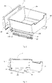
FIG. 3 is a schematic structural diagram of a drawer body in a specific embodiment of the present invention; -
FIG. 4 is a sectional view of the drawer body in a specific embodiment of the present invention; and -
FIG. 5 is an exploded view of a slide assembly in a specific embodiment of the present invention. - The present invention will be described in detail below in conjunction with various embodiments shown in the accompanying drawings.
- The terms representing spatial relative positions, such as "upper", "above", "lower", and "below" as used herein describe the relationship of a unit or feature relative to another unit or feature in the accompanying drawings for the purpose of illustration. The terms of the spatial relative positions may be intended to include different orientations of the device in use or operation except the orientations shown in the drawings. For example, if the device in the drawings is turned over, the units described as "below" or "beneath" other units or features will be "above" other units or features. Thus, the exemplary term "below" can encompass two orientations of "above" and "below". The device may be otherwise oriented (rotated by 90 degrees or facing other directions) and spatially related descriptors used herein are explained accordingly.
- Besides, it should be understood that although the terms of first, second, etc. may be used herein to describe various elements or structures, these described objects should not be limited by them. These terms are merely used to distinguish these described objects. For example, a first jaw may be referred to as a second jaw, and similarly, a second jaw may also be referred to as a first jaw, without departing from the protection scope of the present application.
-
FIG. 1 shows a preferable embodiment of thedrawer assembly structure 10 according to the present invention. Thedrawer assembly structure 10 according to the present invention is configured for mounting a drawer into a cooling compartment (not shown) of a refrigerator. Thedrawer assembly structure 10 comprises adrawer body 11 and aslide assembly 12, wherein thedrawer body 11 is assembled on theslide assembly 12, such that thedrawer body 11 may be pulled out of the cooling compartment. - Referring to
FIGs. 2 to 4 , thedrawer body 11 comprises afront wall 111, arear wall 112 and twoopposite side walls 113, all of which define astorage space 114, and thefront wall 111 is covered with afront drawer cover 110.First jaws 1131 andfirst limiters 1132 are provided on the twoside walls 113 of thedrawer body 11. The present embodiment is explained with one of theside walls 113 as an example. A bottom of theside wall 113 of thedrawer body 11 is recessed towards an interior of thestorage space 114, thefirst jaw 1131 and thefirst limiter 1132 are provided at the recess of theside wall 113 bottom of thedrawer body 11, thefirst limiter 1132 is provided close to thefront wall 111 of thedrawer body 11, and thefirst jaw 1131 is provided close to therear wall 112 of thedrawer body 11. - A
location hole 1111 is provided at a bottom of thefront wall 111 of the drawer body, and a detent 1133 extends from the bottom of the side wall between thefirst limiter 1132 and thefirst jaw 1131. - Referring to
FIG. 5 , theslide assembly 12 comprises aslide support 121 and aslide rail 122 which are assembled together, wherein theslide support 121 further comprises aU-shaped portion 1211 and a first foldedportion 1212 connected therewith fixedly, the first foldedportion 1212 is configured for assembling theslide support 121 and thedrawer body 11 together, and theU-shaped portion 1211 is configured for assembling theslide support 121 and theslide rail 122 together. - The first folded
portion 1212 is provided with a first slot 12121, a firstlimiting hole 12122, ashifter 12123 and abuckle 12124 corresponding to theshifter 12123. Theshifter 12123 is provided close to the first limitinghole 12122 on an inner wall of the first foldedportion 1212, and thebuckle 12124, corresponding to theshifter 12123, is provided on an outer wall of the first foldedportion 1212. - In a process of assembling the
drawer body 11 onto theslide support 121, thefirst jaw 1131 is clipped into the first slot 12121 firstly to prevent a trailing end of thedrawer body 11 from warping, and then a leading end of thedrawer body 11 is pressed, such that thefirst limiter 1132 falls into the first limitinghole 12122 gradually, and thebuckle 12124 falls into thelocation hole 1111. When thedrawer body 11 is assembled at a set position on theslide support 121, thefirst jaw 1131 is clipped into the first slot 12121, and thefirst limiter 1132 is located in the first limitinghole 12122. Preferably, ablock piece 12125 is provided between the U-shapedportion 1211 and the first foldedportion 1212 close to the first limitinghole 12122, and has a shape fitted with a shape of thefirst limiter 1132. The first limitinghole 12122 limits thefirst limiter 1132 in the front and rear direction in cooperation with theblock piece 12125. That is, thedrawer body 11 is limited in the front and rear direction which refers to herein a direction from thefront wall 111 to therear wall 112 of thedrawer body 11. During falling of the leading end of thedrawer body 11, thebuckle 12124 falls into thelocation hole 1111, such that the leading end of thedrawer body 11 is limited in a vertical direction, and the detent 1133 comes into contact with an edge of the first foldedportion 1212. The twodetents 1133 at two sides of thedrawer body 11 come into contact with the edges of the first foldedportions 1212 at respective sides, such that thedrawer body 11 is limited in a radial direction thereof. - When the
drawer body 11 is disassembled from theslide support 121, only theshifter 12123 is required to be lifted upwards, such that thebuckle 12124 is released from thelocation hole 1111, and at least part of thedrawer body 11 is separated from theslide support 121; then the leading end of thedrawer body 11 is lifted towards an inclined top, such that thefirst jaw 1131 is also released from the first slot 12121, and thedrawer body 11 may be separated from theslide support 121 completely. - The
U-shaped portion 1211 comprises twoopposite side walls 12111 and abottom wall 12112 which connects the twoopposite side walls 12111, wherein the bottom wall of theU-shaped portion 1211 is provided with asecond slot 12113 and a second limitinghole 12114. - The
slide rail 122 is provided with asecond limiter 1221 and asecond jaw 1222. When theslide support 121 is assembled at a set position on theslide rail 122, thesecond jaw 1222 is clipped into thesecond slot 12113, and thesecond limiter 1221 is located in the second limitinghole 12114, such that theslide support 121 is limited in the front and rear direction. Meanwhile, theslide rail 122 is located between the twoside walls 12111 of theU-shaped portion 1211. Preferably, a distance between the twoside walls 12111 is matched with a width of theslide rail 122, so as to limit theslide support 121 in a radial direction thereof. Then, ascrew 13 penetrates through one of theside walls 12111 of theU-shaped portion 1211 and theslide rail 122 successively, such that theslide support 121 is fixed onto theslide rail 122. - A second folded
portion 14 is fixed at a bottom of theslide 122, and may be fixed onto an inner wall (not shown) of the cooling compartment through a screw, thereby fixing theentire slide assembly 12 onto the inner wall of the cooling compartment. - The present invention further provides a refrigerator (not shown), which adopts the drawer assembly structure according to the above-mentioned embodiments, thereby obtaining the beneficial effects thereof; in addition, since no improvement is made to other structures or functions of the refrigerator, descriptions thereof are not repeated here.
- It should be understood that although the description is described in terms of embodiments, not every embodiment merely includes one independent technical solution. The statement mode of the description is merely for the sake of clarity, and those skilled that should regard the description as a whole. The technical solutions in the respective embodiments may also be combined as appropriate to form other examples not covered by the invention that can be understood by those skilled in the art.
Claims (10)
- A drawer assembly structure, comprising:a drawer body (11), comprising a front wall (111), a rear wall (112) and two opposite side walls (113), all of which define a storage space (114), wherein a first jaw (1131) and a first limiter (1132) are provided on the side wall (113) of the drawer body (11),characterized by a location hole (1111) on the front wall (111) of the drawer body (11);and by a slide assembly (12), comprising a slide support (121) and a slide rail (122), wherein the slide support (121) comprises a U-shaped portion (1211) and a first folded portion (1212) connected with the U-shaped portion (1211) fixedly, the U-shaped portion (1211) is configured for assembling the slide support (121) and the slide rail (122),and the first folded portion (1212) is configured for assembling the drawer body (11) and the slide support (121), the first folded portion (1211) is provided with a first slot (12121), a first limiting hole (12122). a shifter (12123) and a buckle (12124) corresponding to the shifter (12123);when the drawer body (11) is assembled at a set position on the slide support (121), the first jaw (1131) is clipped into the first slot (12121), the first limiter (1132) falls into the first limiting hole (12122), and the buckle (12124) is located in the location hole (1111);when the drawer body (11) body is disassembled from the slide support (121), the shifter (12123) is lifted to release the buckle (12124) from the location hole (1111),and at least part of the drawer body (11) is separated from the slide support (121).
- The drawer assembly structure according to claim 1, wherein the U-shaped portion (1211) is provided with a second slot (12113) and a second limiting hole (12114), and the slide rail (122) is provided with a second limiter (1221) and a second jaw (1222); when the slide support (121) is assembled at a set position on the slide rail (122), the second jaw (1222) is clipped into the second slot (12113), and the second limiter (1221) is located in the second limiting hole (12114).
- The drawer assembly structure according to claim 2, wherein the U-shaped portion (1211) comprises two opposite side walls (12111) and a bottom wall (12112) which connects the two opposite side walls (12111); when the slide support (121) is assembled at the set position on the slide rail (122), the slide rail (122) is located between the two side walls (12111) of the U-shaped portion (1211), and a distance between the two side walls (12111) is matched with a width of the slide rail (122), so as to limit the slide support (121) in a radial direction thereof.
- The drawer assembly structure according to claim 3, wherein when the slide support (121) is assembled at the set position on the slide rail (122), a screw penetrates through one of the side walls (12111) of the U-shaped portion (1211) and the slide rail (122) successively, such that the slide support (121) is fixed onto the slide rail (122).
- The drawer assembly structure according to claim 3, wherein both the second slot (12113) and the second limiting hole (12114) are provided on the bottom wall of the U-shaped portion (1211).
- The drawer assembly structure according to claim 1, wherein a bottom of the side wall (113) of the drawer body (11) body is recessed towards an interior of the storage space, the first limiter (1132) and the first jaw (1131) are provided at the recess of the side wall bottom of the drawer body (11), the first limiter (1132) is provided close to the front wall (111) of the drawer body (11), and the first jaw (1131) is provided close to the rear wall (112) of the drawer body (11).
- The drawer assembly structure according to claim 6, wherein a detent extends from the bottom of the side wall (113) between the first limiter (1132) and the first jaw (1131), and when the drawer body (11) is assembled at the set position on the slide support (121), the detent comes into contact with an edge of the first folded portion (1212), such that the drawer body (11) is limited in the radial direction thereof.
- The drawer assembly structure according to claim 1, wherein a block piece (12125) is provided between the U-shaped portion (1211) and the first folded portion (1212) close to the first limiting hole (12122), and limits the first limiter (1132) in the front and rear direction in cooperation with the first limiting hole (12122).
- The drawer assembly structure according to claim 1, wherein the shifter (12123) is provided on an inner wall of the folded portion (1212) close to the first limiting hole (12122), and the buckle (12124), corresponding to the shifter (12123), is provided on an outer wall of the folded portion (1212).
- A refrigerator, comprising the drawer assembly structure according to claim 1.
Applications Claiming Priority (2)
| Application Number | Priority Date | Filing Date | Title |
|---|---|---|---|
| CN201711299036.4A CN108286865B (en) | 2017-12-08 | 2017-12-08 | Drawer assembly structure and refrigerator with same |
| PCT/CN2018/112302 WO2019109755A1 (en) | 2017-12-08 | 2018-10-29 | Drawer assembly structure and refrigerator having same |
Publications (3)
| Publication Number | Publication Date |
|---|---|
| EP3722715A1 EP3722715A1 (en) | 2020-10-14 |
| EP3722715A4 EP3722715A4 (en) | 2021-01-20 |
| EP3722715B1 true EP3722715B1 (en) | 2022-06-22 |
Family
ID=62831790
Family Applications (1)
| Application Number | Title | Priority Date | Filing Date |
|---|---|---|---|
| EP18886891.3A Active EP3722715B1 (en) | 2017-12-08 | 2018-10-29 | Drawer assembly structure and refrigerator having same |
Country Status (3)
| Country | Link |
|---|---|
| EP (1) | EP3722715B1 (en) |
| CN (1) | CN108286865B (en) |
| WO (1) | WO2019109755A1 (en) |
Families Citing this family (11)
| Publication number | Priority date | Publication date | Assignee | Title |
|---|---|---|---|---|
| CN108286865B (en) * | 2017-12-08 | 2019-12-06 | 青岛海尔股份有限公司 | Drawer assembly structure and refrigerator with same |
| CN109028741B (en) * | 2018-10-17 | 2020-12-11 | 合肥华凌股份有限公司 | Drawer installation structure and refrigerator |
| CN109764614B (en) * | 2018-12-21 | 2020-11-20 | 海尔智家股份有限公司 | Drawer assembly structure and refrigerator having the same |
| CN112444035B (en) * | 2019-09-03 | 2023-11-17 | 博西华电器(江苏)有限公司 | Refrigeration appliances |
| JP7456853B2 (en) * | 2020-05-29 | 2024-03-27 | 東芝ライフスタイル株式会社 | refrigerator |
| CN111879047A (en) * | 2020-07-09 | 2020-11-03 | 海信容声(广东)冰箱有限公司 | A kind of refrigerator |
| CN112140451A (en) * | 2020-09-15 | 2020-12-29 | 长虹美菱股份有限公司 | Refrigerator box foaming mould location detects instrument |
| CN116123806B (en) * | 2021-11-15 | 2025-05-13 | 青岛海尔电冰箱有限公司 | Drawer assembly for refrigerator and refrigerator |
| CN114979802B (en) * | 2021-12-30 | 2025-03-25 | 安徽英福泰克信息科技有限公司 | A switch fixing component that is easy to install |
| CN117053472A (en) * | 2023-08-23 | 2023-11-14 | 澳柯玛股份有限公司 | A slide rail precise positioning structure and refrigerator |
| US20260049756A1 (en) * | 2024-08-15 | 2026-02-19 | Whirlpool Corporation | Refrigerator and storage system for a refrigerator |
Family Cites Families (19)
| Publication number | Priority date | Publication date | Assignee | Title |
|---|---|---|---|---|
| KR100367370B1 (en) * | 2000-04-21 | 2003-01-09 | 박윤식 | Drawing slider for keeping equipment |
| CN101169303B (en) * | 2006-10-25 | 2010-12-29 | 海尔集团公司 | Inner wall positioning installation mechanism of drawer slide rail and installation method thereof |
| US20080265730A1 (en) * | 2007-04-26 | 2008-10-30 | Nan Juen International Co., Ltd. | Fixing apparatus with drawer rails for quick external installation and disassembly |
| DE202009016105U1 (en) * | 2009-07-06 | 2010-12-02 | Paul Hettich Gmbh & Co. Kg | Synchronous guide a push element and furniture |
| MY151706A (en) * | 2009-08-12 | 2014-06-30 | Harn Marketing Sdn Bhd | Drawer assembly |
| CN201503184U (en) * | 2009-09-10 | 2010-06-09 | 海尔集团公司 | Fixing and dismounting structure of refrigeration equipment and its drawers |
| TW201200828A (en) * | 2010-03-25 | 2012-01-01 | Panasonic Corp | Refrigerator |
| US20130043780A1 (en) * | 2011-03-02 | 2013-02-21 | Panasonic Corporation | Refrigerator |
| JP5246315B2 (en) * | 2011-03-02 | 2013-07-24 | パナソニック株式会社 | refrigerator |
| CN202027153U (en) * | 2011-03-19 | 2011-11-09 | 陈明开 | Quick-disassembling type drawer rails |
| CN102954656B (en) * | 2011-08-27 | 2016-09-28 | 博西华电器(江苏)有限公司 | Household electrical appliance |
| JP2013204828A (en) * | 2012-03-27 | 2013-10-07 | Panasonic Corp | Refrigerator |
| KR101893132B1 (en) * | 2011-11-16 | 2018-08-31 | 주식회사 대유위니아 | A refrigerator in use with auto drawer |
| KR101899808B1 (en) * | 2011-11-18 | 2018-09-20 | 엘지전자 주식회사 | Refrigerator |
| CN103292561B (en) * | 2013-05-28 | 2016-03-30 | 海尔集团公司 | Refrigerator drawer |
| CN203550402U (en) * | 2013-09-30 | 2014-04-16 | 合肥晶弘电器有限公司 | Refrigerator drawer sliding rail system |
| CN103919375B (en) * | 2014-04-25 | 2016-03-02 | 无锡海达尔精密滑轨有限公司 | Three-section type concealed slide track mechanism |
| KR20170116868A (en) * | 2016-04-12 | 2017-10-20 | 동부대우전자 주식회사 | Refrigerator and drawer guide assembly thereof |
| CN108286865B (en) * | 2017-12-08 | 2019-12-06 | 青岛海尔股份有限公司 | Drawer assembly structure and refrigerator with same |
-
2017
- 2017-12-08 CN CN201711299036.4A patent/CN108286865B/en active Active
-
2018
- 2018-10-29 EP EP18886891.3A patent/EP3722715B1/en active Active
- 2018-10-29 WO PCT/CN2018/112302 patent/WO2019109755A1/en not_active Ceased
Also Published As
| Publication number | Publication date |
|---|---|
| EP3722715A1 (en) | 2020-10-14 |
| CN108286865B (en) | 2019-12-06 |
| WO2019109755A1 (en) | 2019-06-13 |
| CN108286865A (en) | 2018-07-17 |
| EP3722715A4 (en) | 2021-01-20 |
Similar Documents
| Publication | Publication Date | Title |
|---|---|---|
| EP3722715A1 (en) | Drawer assembly structure and refrigerator having same | |
| US7458548B2 (en) | Removable shelf locking system | |
| US11140985B2 (en) | Trim assembly for an appliance shelf | |
| US11079167B2 (en) | Storage device and refrigerator having the same | |
| US20150108134A1 (en) | Apparatus that includes a suction cup mount | |
| CN101903726A (en) | refrigeration device | |
| EP3842717B1 (en) | Side wall attachment system for extractable wine shelves | |
| US7950552B2 (en) | Gun cover with securing assembly | |
| CN102645078A (en) | Refrigerator and shelf | |
| US10495372B2 (en) | Refrigerator | |
| US20080164797A1 (en) | Refrigerator and shelf for the same | |
| EP2612091B1 (en) | Shelf device | |
| US4574424A (en) | Handle and pull-out part on cupboards and shelves | |
| CN104344674B (en) | Refrigerator slideway shelf | |
| CN108344240B (en) | Drawer assembly structure and refrigerator with same | |
| EP2937017B1 (en) | Mounting device for drawer system | |
| KR20150110016A (en) | Drawer for refrigerator | |
| CN216080526U (en) | Refrigerator with a door | |
| CN110411129A (en) | Rack assembly and refrigeration equipment | |
| CN211372885U (en) | refrigerator | |
| CN102564036A (en) | Refrigerator and combined wine rack for same | |
| CN209135757U (en) | A kind of sliding rail for drawer component, drawer and refrigerating box | |
| KR20160048495A (en) | Shelf for the rerfigerator | |
| US20180356029A1 (en) | Hanger Assembly | |
| CN208319091U (en) | A kind of cookware that handle is removable |
Legal Events
| Date | Code | Title | Description |
|---|---|---|---|
| STAA | Information on the status of an ep patent application or granted ep patent |
Free format text: STATUS: THE INTERNATIONAL PUBLICATION HAS BEEN MADE |
|
| PUAI | Public reference made under article 153(3) epc to a published international application that has entered the european phase |
Free format text: ORIGINAL CODE: 0009012 |
|
| STAA | Information on the status of an ep patent application or granted ep patent |
Free format text: STATUS: REQUEST FOR EXAMINATION WAS MADE |
|
| 17P | Request for examination filed |
Effective date: 20191121 |
|
| AK | Designated contracting states |
Kind code of ref document: A1 Designated state(s): AL AT BE BG CH CY CZ DE DK EE ES FI FR GB GR HR HU IE IS IT LI LT LU LV MC MK MT NL NO PL PT RO RS SE SI SK SM TR |
|
| AX | Request for extension of the european patent |
Extension state: BA ME |
|
| A4 | Supplementary search report drawn up and despatched |
Effective date: 20201218 |
|
| RIC1 | Information provided on ipc code assigned before grant |
Ipc: F25D 25/02 20060101AFI20201214BHEP Ipc: A47B 88/90 20170101ALI20201214BHEP |
|
| DAV | Request for validation of the european patent (deleted) | ||
| DAX | Request for extension of the european patent (deleted) | ||
| RIC1 | Information provided on ipc code assigned before grant |
Ipc: A47B 88/427 20170101ALI20211008BHEP Ipc: A47B 88/90 20170101ALI20211008BHEP Ipc: F25D 25/02 20060101AFI20211008BHEP |
|
| GRAP | Despatch of communication of intention to grant a patent |
Free format text: ORIGINAL CODE: EPIDOSNIGR1 |
|
| STAA | Information on the status of an ep patent application or granted ep patent |
Free format text: STATUS: GRANT OF PATENT IS INTENDED |
|
| INTG | Intention to grant announced |
Effective date: 20220121 |
|
| GRAS | Grant fee paid |
Free format text: ORIGINAL CODE: EPIDOSNIGR3 |
|
| GRAA | (expected) grant |
Free format text: ORIGINAL CODE: 0009210 |
|
| STAA | Information on the status of an ep patent application or granted ep patent |
Free format text: STATUS: THE PATENT HAS BEEN GRANTED |
|
| AK | Designated contracting states |
Kind code of ref document: B1 Designated state(s): AL AT BE BG CH CY CZ DE DK EE ES FI FR GB GR HR HU IE IS IT LI LT LU LV MC MK MT NL NO PL PT RO RS SE SI SK SM TR |
|
| REG | Reference to a national code |
Ref country code: GB Ref legal event code: FG4D |
|
| REG | Reference to a national code |
Ref country code: CH Ref legal event code: EP |
|
| REG | Reference to a national code |
Ref country code: DE Ref legal event code: R096 Ref document number: 602018037166 Country of ref document: DE |
|
| REG | Reference to a national code |
Ref country code: AT Ref legal event code: REF Ref document number: 1500009 Country of ref document: AT Kind code of ref document: T Effective date: 20220715 |
|
| REG | Reference to a national code |
Ref country code: IE Ref legal event code: FG4D |
|
| REG | Reference to a national code |
Ref country code: LT Ref legal event code: MG9D |
|
| REG | Reference to a national code |
Ref country code: NL Ref legal event code: MP Effective date: 20220622 |
|
| PG25 | Lapsed in a contracting state [announced via postgrant information from national office to epo] |
Ref country code: SE Free format text: LAPSE BECAUSE OF FAILURE TO SUBMIT A TRANSLATION OF THE DESCRIPTION OR TO PAY THE FEE WITHIN THE PRESCRIBED TIME-LIMIT Effective date: 20220622 Ref country code: NO Free format text: LAPSE BECAUSE OF FAILURE TO SUBMIT A TRANSLATION OF THE DESCRIPTION OR TO PAY THE FEE WITHIN THE PRESCRIBED TIME-LIMIT Effective date: 20220922 Ref country code: LT Free format text: LAPSE BECAUSE OF FAILURE TO SUBMIT A TRANSLATION OF THE DESCRIPTION OR TO PAY THE FEE WITHIN THE PRESCRIBED TIME-LIMIT Effective date: 20220622 Ref country code: HR Free format text: LAPSE BECAUSE OF FAILURE TO SUBMIT A TRANSLATION OF THE DESCRIPTION OR TO PAY THE FEE WITHIN THE PRESCRIBED TIME-LIMIT Effective date: 20220622 Ref country code: GR Free format text: LAPSE BECAUSE OF FAILURE TO SUBMIT A TRANSLATION OF THE DESCRIPTION OR TO PAY THE FEE WITHIN THE PRESCRIBED TIME-LIMIT Effective date: 20220923 Ref country code: FI Free format text: LAPSE BECAUSE OF FAILURE TO SUBMIT A TRANSLATION OF THE DESCRIPTION OR TO PAY THE FEE WITHIN THE PRESCRIBED TIME-LIMIT Effective date: 20220622 Ref country code: BG Free format text: LAPSE BECAUSE OF FAILURE TO SUBMIT A TRANSLATION OF THE DESCRIPTION OR TO PAY THE FEE WITHIN THE PRESCRIBED TIME-LIMIT Effective date: 20220922 |
|
| REG | Reference to a national code |
Ref country code: AT Ref legal event code: MK05 Ref document number: 1500009 Country of ref document: AT Kind code of ref document: T Effective date: 20220622 |
|
| PG25 | Lapsed in a contracting state [announced via postgrant information from national office to epo] |
Ref country code: RS Free format text: LAPSE BECAUSE OF FAILURE TO SUBMIT A TRANSLATION OF THE DESCRIPTION OR TO PAY THE FEE WITHIN THE PRESCRIBED TIME-LIMIT Effective date: 20220622 Ref country code: LV Free format text: LAPSE BECAUSE OF FAILURE TO SUBMIT A TRANSLATION OF THE DESCRIPTION OR TO PAY THE FEE WITHIN THE PRESCRIBED TIME-LIMIT Effective date: 20220622 |
|
| PG25 | Lapsed in a contracting state [announced via postgrant information from national office to epo] |
Ref country code: NL Free format text: LAPSE BECAUSE OF FAILURE TO SUBMIT A TRANSLATION OF THE DESCRIPTION OR TO PAY THE FEE WITHIN THE PRESCRIBED TIME-LIMIT Effective date: 20220622 |
|
| PG25 | Lapsed in a contracting state [announced via postgrant information from national office to epo] |
Ref country code: SM Free format text: LAPSE BECAUSE OF FAILURE TO SUBMIT A TRANSLATION OF THE DESCRIPTION OR TO PAY THE FEE WITHIN THE PRESCRIBED TIME-LIMIT Effective date: 20220622 Ref country code: SK Free format text: LAPSE BECAUSE OF FAILURE TO SUBMIT A TRANSLATION OF THE DESCRIPTION OR TO PAY THE FEE WITHIN THE PRESCRIBED TIME-LIMIT Effective date: 20220622 Ref country code: RO Free format text: LAPSE BECAUSE OF FAILURE TO SUBMIT A TRANSLATION OF THE DESCRIPTION OR TO PAY THE FEE WITHIN THE PRESCRIBED TIME-LIMIT Effective date: 20220622 Ref country code: PT Free format text: LAPSE BECAUSE OF FAILURE TO SUBMIT A TRANSLATION OF THE DESCRIPTION OR TO PAY THE FEE WITHIN THE PRESCRIBED TIME-LIMIT Effective date: 20221024 Ref country code: ES Free format text: LAPSE BECAUSE OF FAILURE TO SUBMIT A TRANSLATION OF THE DESCRIPTION OR TO PAY THE FEE WITHIN THE PRESCRIBED TIME-LIMIT Effective date: 20220622 Ref country code: EE Free format text: LAPSE BECAUSE OF FAILURE TO SUBMIT A TRANSLATION OF THE DESCRIPTION OR TO PAY THE FEE WITHIN THE PRESCRIBED TIME-LIMIT Effective date: 20220622 Ref country code: CZ Free format text: LAPSE BECAUSE OF FAILURE TO SUBMIT A TRANSLATION OF THE DESCRIPTION OR TO PAY THE FEE WITHIN THE PRESCRIBED TIME-LIMIT Effective date: 20220622 Ref country code: AT Free format text: LAPSE BECAUSE OF FAILURE TO SUBMIT A TRANSLATION OF THE DESCRIPTION OR TO PAY THE FEE WITHIN THE PRESCRIBED TIME-LIMIT Effective date: 20220622 |
|
| PG25 | Lapsed in a contracting state [announced via postgrant information from national office to epo] |
Ref country code: PL Free format text: LAPSE BECAUSE OF FAILURE TO SUBMIT A TRANSLATION OF THE DESCRIPTION OR TO PAY THE FEE WITHIN THE PRESCRIBED TIME-LIMIT Effective date: 20220622 Ref country code: IS Free format text: LAPSE BECAUSE OF FAILURE TO SUBMIT A TRANSLATION OF THE DESCRIPTION OR TO PAY THE FEE WITHIN THE PRESCRIBED TIME-LIMIT Effective date: 20221022 |
|
| REG | Reference to a national code |
Ref country code: DE Ref legal event code: R097 Ref document number: 602018037166 Country of ref document: DE |
|
| PG25 | Lapsed in a contracting state [announced via postgrant information from national office to epo] |
Ref country code: AL Free format text: LAPSE BECAUSE OF FAILURE TO SUBMIT A TRANSLATION OF THE DESCRIPTION OR TO PAY THE FEE WITHIN THE PRESCRIBED TIME-LIMIT Effective date: 20220622 |
|
| PG25 | Lapsed in a contracting state [announced via postgrant information from national office to epo] |
Ref country code: DK Free format text: LAPSE BECAUSE OF FAILURE TO SUBMIT A TRANSLATION OF THE DESCRIPTION OR TO PAY THE FEE WITHIN THE PRESCRIBED TIME-LIMIT Effective date: 20220622 |
|
| PLBE | No opposition filed within time limit |
Free format text: ORIGINAL CODE: 0009261 |
|
| STAA | Information on the status of an ep patent application or granted ep patent |
Free format text: STATUS: NO OPPOSITION FILED WITHIN TIME LIMIT |
|
| 26N | No opposition filed |
Effective date: 20230323 |
|
| PG25 | Lapsed in a contracting state [announced via postgrant information from national office to epo] |
Ref country code: MC Free format text: LAPSE BECAUSE OF FAILURE TO SUBMIT A TRANSLATION OF THE DESCRIPTION OR TO PAY THE FEE WITHIN THE PRESCRIBED TIME-LIMIT Effective date: 20220622 |
|
| REG | Reference to a national code |
Ref country code: CH Ref legal event code: PL |
|
| REG | Reference to a national code |
Ref country code: BE Ref legal event code: MM Effective date: 20221031 |
|
| PG25 | Lapsed in a contracting state [announced via postgrant information from national office to epo] |
Ref country code: LU Free format text: LAPSE BECAUSE OF NON-PAYMENT OF DUE FEES Effective date: 20221029 |
|
| PG25 | Lapsed in a contracting state [announced via postgrant information from national office to epo] |
Ref country code: LI Free format text: LAPSE BECAUSE OF NON-PAYMENT OF DUE FEES Effective date: 20221031 Ref country code: CH Free format text: LAPSE BECAUSE OF NON-PAYMENT OF DUE FEES Effective date: 20221031 |
|
| PG25 | Lapsed in a contracting state [announced via postgrant information from national office to epo] |
Ref country code: SI Free format text: LAPSE BECAUSE OF FAILURE TO SUBMIT A TRANSLATION OF THE DESCRIPTION OR TO PAY THE FEE WITHIN THE PRESCRIBED TIME-LIMIT Effective date: 20220622 |
|
| PG25 | Lapsed in a contracting state [announced via postgrant information from national office to epo] |
Ref country code: BE Free format text: LAPSE BECAUSE OF NON-PAYMENT OF DUE FEES Effective date: 20221031 |
|
| PG25 | Lapsed in a contracting state [announced via postgrant information from national office to epo] |
Ref country code: IE Free format text: LAPSE BECAUSE OF NON-PAYMENT OF DUE FEES Effective date: 20221029 |
|
| PG25 | Lapsed in a contracting state [announced via postgrant information from national office to epo] |
Ref country code: IT Free format text: LAPSE BECAUSE OF FAILURE TO SUBMIT A TRANSLATION OF THE DESCRIPTION OR TO PAY THE FEE WITHIN THE PRESCRIBED TIME-LIMIT Effective date: 20220622 |
|
| PG25 | Lapsed in a contracting state [announced via postgrant information from national office to epo] |
Ref country code: CY Free format text: LAPSE BECAUSE OF FAILURE TO SUBMIT A TRANSLATION OF THE DESCRIPTION OR TO PAY THE FEE WITHIN THE PRESCRIBED TIME-LIMIT Effective date: 20220622 |
|
| PG25 | Lapsed in a contracting state [announced via postgrant information from national office to epo] |
Ref country code: MK Free format text: LAPSE BECAUSE OF FAILURE TO SUBMIT A TRANSLATION OF THE DESCRIPTION OR TO PAY THE FEE WITHIN THE PRESCRIBED TIME-LIMIT Effective date: 20220622 Ref country code: HU Free format text: LAPSE BECAUSE OF FAILURE TO SUBMIT A TRANSLATION OF THE DESCRIPTION OR TO PAY THE FEE WITHIN THE PRESCRIBED TIME-LIMIT; INVALID AB INITIO Effective date: 20181029 |
|
| PG25 | Lapsed in a contracting state [announced via postgrant information from national office to epo] |
Ref country code: MT Free format text: LAPSE BECAUSE OF FAILURE TO SUBMIT A TRANSLATION OF THE DESCRIPTION OR TO PAY THE FEE WITHIN THE PRESCRIBED TIME-LIMIT Effective date: 20220622 |
|
| PG25 | Lapsed in a contracting state [announced via postgrant information from national office to epo] |
Ref country code: BG Free format text: LAPSE BECAUSE OF FAILURE TO SUBMIT A TRANSLATION OF THE DESCRIPTION OR TO PAY THE FEE WITHIN THE PRESCRIBED TIME-LIMIT Effective date: 20220622 |
|
| PG25 | Lapsed in a contracting state [announced via postgrant information from national office to epo] |
Ref country code: BG Free format text: LAPSE BECAUSE OF FAILURE TO SUBMIT A TRANSLATION OF THE DESCRIPTION OR TO PAY THE FEE WITHIN THE PRESCRIBED TIME-LIMIT Effective date: 20220622 |
|
| PG25 | Lapsed in a contracting state [announced via postgrant information from national office to epo] |
Ref country code: TR Free format text: LAPSE BECAUSE OF FAILURE TO SUBMIT A TRANSLATION OF THE DESCRIPTION OR TO PAY THE FEE WITHIN THE PRESCRIBED TIME-LIMIT Effective date: 20220622 |
|
| PGFP | Annual fee paid to national office [announced via postgrant information from national office to epo] |
Ref country code: DE Payment date: 20251015 Year of fee payment: 8 |
|
| PGFP | Annual fee paid to national office [announced via postgrant information from national office to epo] |
Ref country code: GB Payment date: 20251023 Year of fee payment: 8 |
|
| PGFP | Annual fee paid to national office [announced via postgrant information from national office to epo] |
Ref country code: FR Payment date: 20251027 Year of fee payment: 8 |