EP3722663B1 - Optische einheit, die einen lichtstrahl mit hell-dunkel-grenze erzeugen kann - Google Patents
Optische einheit, die einen lichtstrahl mit hell-dunkel-grenze erzeugen kann Download PDFInfo
- Publication number
- EP3722663B1 EP3722663B1 EP20164742.7A EP20164742A EP3722663B1 EP 3722663 B1 EP3722663 B1 EP 3722663B1 EP 20164742 A EP20164742 A EP 20164742A EP 3722663 B1 EP3722663 B1 EP 3722663B1
- Authority
- EP
- European Patent Office
- Prior art keywords
- optical
- optical part
- face
- edge
- downstream
- Prior art date
- Legal status (The legal status is an assumption and is not a legal conclusion. Google has not performed a legal analysis and makes no representation as to the accuracy of the status listed.)
- Active
Links
Images


Classifications
-
- F—MECHANICAL ENGINEERING; LIGHTING; HEATING; WEAPONS; BLASTING
- F21—LIGHTING
- F21S—NON-PORTABLE LIGHTING DEVICES; SYSTEMS THEREOF; VEHICLE LIGHTING DEVICES SPECIALLY ADAPTED FOR VEHICLE EXTERIORS
- F21S41/00—Illuminating devices specially adapted for vehicle exteriors, e.g. headlamps
- F21S41/20—Illuminating devices specially adapted for vehicle exteriors, e.g. headlamps characterised by refractors, transparent cover plates, light guides or filters
- F21S41/24—Light guides
-
- F—MECHANICAL ENGINEERING; LIGHTING; HEATING; WEAPONS; BLASTING
- F21—LIGHTING
- F21S—NON-PORTABLE LIGHTING DEVICES; SYSTEMS THEREOF; VEHICLE LIGHTING DEVICES SPECIALLY ADAPTED FOR VEHICLE EXTERIORS
- F21S41/00—Illuminating devices specially adapted for vehicle exteriors, e.g. headlamps
- F21S41/10—Illuminating devices specially adapted for vehicle exteriors, e.g. headlamps characterised by the light source
- F21S41/14—Illuminating devices specially adapted for vehicle exteriors, e.g. headlamps characterised by the light source characterised by the type of light source
- F21S41/141—Light emitting diodes [LED]
- F21S41/147—Light emitting diodes [LED] the main emission direction of the LED being angled to the optical axis of the illuminating device
-
- F—MECHANICAL ENGINEERING; LIGHTING; HEATING; WEAPONS; BLASTING
- F21—LIGHTING
- F21S—NON-PORTABLE LIGHTING DEVICES; SYSTEMS THEREOF; VEHICLE LIGHTING DEVICES SPECIALLY ADAPTED FOR VEHICLE EXTERIORS
- F21S41/00—Illuminating devices specially adapted for vehicle exteriors, e.g. headlamps
- F21S41/20—Illuminating devices specially adapted for vehicle exteriors, e.g. headlamps characterised by refractors, transparent cover plates, light guides or filters
- F21S41/25—Projection lenses
- F21S41/255—Lenses with a front view of circular or truncated circular outline
-
- F—MECHANICAL ENGINEERING; LIGHTING; HEATING; WEAPONS; BLASTING
- F21—LIGHTING
- F21S—NON-PORTABLE LIGHTING DEVICES; SYSTEMS THEREOF; VEHICLE LIGHTING DEVICES SPECIALLY ADAPTED FOR VEHICLE EXTERIORS
- F21S41/00—Illuminating devices specially adapted for vehicle exteriors, e.g. headlamps
- F21S41/20—Illuminating devices specially adapted for vehicle exteriors, e.g. headlamps characterised by refractors, transparent cover plates, light guides or filters
- F21S41/29—Attachment thereof
-
- F—MECHANICAL ENGINEERING; LIGHTING; HEATING; WEAPONS; BLASTING
- F21—LIGHTING
- F21S—NON-PORTABLE LIGHTING DEVICES; SYSTEMS THEREOF; VEHICLE LIGHTING DEVICES SPECIALLY ADAPTED FOR VEHICLE EXTERIORS
- F21S41/00—Illuminating devices specially adapted for vehicle exteriors, e.g. headlamps
- F21S41/30—Illuminating devices specially adapted for vehicle exteriors, e.g. headlamps characterised by reflectors
- F21S41/32—Optical layout thereof
- F21S41/322—Optical layout thereof the reflector using total internal reflection
-
- F—MECHANICAL ENGINEERING; LIGHTING; HEATING; WEAPONS; BLASTING
- F21—LIGHTING
- F21S—NON-PORTABLE LIGHTING DEVICES; SYSTEMS THEREOF; VEHICLE LIGHTING DEVICES SPECIALLY ADAPTED FOR VEHICLE EXTERIORS
- F21S41/00—Illuminating devices specially adapted for vehicle exteriors, e.g. headlamps
- F21S41/40—Illuminating devices specially adapted for vehicle exteriors, e.g. headlamps characterised by screens, non-reflecting members, light-shielding members or fixed shades
- F21S41/43—Illuminating devices specially adapted for vehicle exteriors, e.g. headlamps characterised by screens, non-reflecting members, light-shielding members or fixed shades characterised by the shape thereof
-
- F—MECHANICAL ENGINEERING; LIGHTING; HEATING; WEAPONS; BLASTING
- F21—LIGHTING
- F21S—NON-PORTABLE LIGHTING DEVICES; SYSTEMS THEREOF; VEHICLE LIGHTING DEVICES SPECIALLY ADAPTED FOR VEHICLE EXTERIORS
- F21S41/00—Illuminating devices specially adapted for vehicle exteriors, e.g. headlamps
- F21S41/40—Illuminating devices specially adapted for vehicle exteriors, e.g. headlamps characterised by screens, non-reflecting members, light-shielding members or fixed shades
- F21S41/47—Attachment thereof
-
- F—MECHANICAL ENGINEERING; LIGHTING; HEATING; WEAPONS; BLASTING
- F21—LIGHTING
- F21S—NON-PORTABLE LIGHTING DEVICES; SYSTEMS THEREOF; VEHICLE LIGHTING DEVICES SPECIALLY ADAPTED FOR VEHICLE EXTERIORS
- F21S41/00—Illuminating devices specially adapted for vehicle exteriors, e.g. headlamps
- F21S41/60—Illuminating devices specially adapted for vehicle exteriors, e.g. headlamps characterised by a variable light distribution
- F21S41/65—Illuminating devices specially adapted for vehicle exteriors, e.g. headlamps characterised by a variable light distribution by acting on light sources
- F21S41/663—Illuminating devices specially adapted for vehicle exteriors, e.g. headlamps characterised by a variable light distribution by acting on light sources by switching light sources
-
- F—MECHANICAL ENGINEERING; LIGHTING; HEATING; WEAPONS; BLASTING
- F21—LIGHTING
- F21W—INDEXING SCHEME ASSOCIATED WITH SUBCLASSES F21K, F21L, F21S and F21V, RELATING TO USES OR APPLICATIONS OF LIGHTING DEVICES OR SYSTEMS
- F21W2102/00—Exterior vehicle lighting devices for illuminating purposes
- F21W2102/10—Arrangement or contour of the emitted light
- F21W2102/13—Arrangement or contour of the emitted light for high-beam region or low-beam region
- F21W2102/135—Arrangement or contour of the emitted light for high-beam region or low-beam region the light having cut-off lines, i.e. clear borderlines between emitted regions and dark regions
-
- F—MECHANICAL ENGINEERING; LIGHTING; HEATING; WEAPONS; BLASTING
- F21—LIGHTING
- F21W—INDEXING SCHEME ASSOCIATED WITH SUBCLASSES F21K, F21L, F21S and F21V, RELATING TO USES OR APPLICATIONS OF LIGHTING DEVICES OR SYSTEMS
- F21W2107/00—Use or application of lighting devices on or in particular types of vehicles
- F21W2107/10—Use or application of lighting devices on or in particular types of vehicles for land vehicles
Definitions
- the present invention relates to the field of motor vehicle lighting. Specifically, the invention relates to an optical assembly capable of generating a light beam having a cut-off line and to a light module comprising such an optical module.
- Said beam also called cut-off beam
- the beam having a cut-off line may be a beam complementary to the dipped beam and configured in such a way that the combination of said complementary beam with the dipped beam forms a driving beam.
- optical parts are arranged to send light rays to specific locations.
- an assembly may comprise an elliptical reflector, a bender and a converging lens located downstream of the reflector and of the bender.
- a disadvantage of this type of optical part is that it requires a high degree of precision in the positioning of the parts relative to each other for precise and efficient reflection, so as to have a sharp and precise cut-off line. positioned.
- an objective of the invention is to propose an optical system generating a cut-off beam having a sharp and precisely positioned cut-off line.
- Said optical assembly further comprises a reflective material separate from the material of the first optical part and placed on said first face, the reflective material extending from the cut-off edge towards the elementary outputs. Furthermore, the reflective material and the first optical part are arranged in such a way as to be held together without an additional part and in such a way that the reflective material is in direct contact with the cut-off edge.
- the production of a means of reflection by the addition of the reflecting material on the first one-piece optical part makes it possible to overcome these positioning problems for the reflection members while having good reflection efficiency.
- the image of the beam generated by the optical assembly according to the invention is therefore clear and precise.
- the reflective material is fixed to the first optical part by means of plating members. According to the invention, direct contact between the reflective material and the cut-off edge is made with all of said cut-off edge.
- the reflective material is formed by a separate reflection member from the first optical part.
- the reflective material has a reflectivity rate of at least 85%. Thus, there is less loss of light rays.
- the reflective material when the reflective material is formed by a reflective coating, the latter is made of aluminum or silver, in particular formed by a deposit, such as aluminizing.
- the process for manufacturing the reflective material is simple and inexpensive.
- the reflective material is formed by a separate reflection member from the first optical part and having a first face
- said first optical part comprises at least one plating member arranged so that the first face of the reflection member is in direct contact with the cut-off edge, said first optical part and the plating member being formed in a single, one-piece piece.
- the space between the reflective material and the cut-off edge of the first optical part is eliminated.
- the reflective material perfectly matches the cut-off edge of the first optical part, which prevents the formation of black bands at the level of the cut-off line on the projected image of the beam generated by the optical assembly.
- the plating member being made in one piece with the first optical part, this therefore simplifies the assembly of the first optical part with the reflection member and makes it possible to eliminate assembly irregularities due to a third-party fixing means.
- the first face of the reflection member has a downstream central portion. Direct contact between the reflective material and the cut-off edge is made with this downstream central portion. Furthermore, this central portion is in direct contact with the first optical part only on the cut-off edge.
- the downstream central portion is delimited downstream by a downstream edge, the direct contact between the downstream central portion and the first optical part being formed by the direct contact of said downstream edge with the entire cut-off edge. This therefore involves edge-to-edge contact between the reflection member and the first optical part.
- the reflection member has the first face on one side and a second face on the other side, the second face being reflective.
- the first optical part comprises abutment members in contact with abutments of the reflection member so as to block the movement of the reflection member relative to the first optical part according to at least one of these three axes.
- the reflection member is fixed immobile with respect to the first optical part along at least one of the three axes, which makes it possible to avoid poor positioning between these two parts which can degrade the beam emitted by the assembly. optical.
- At least one of the abutment members is arranged so as to press the reflection member against the cut-off edge.
- the abutment member and the pressing member are made in one piece.
- the reflection member comprises at least one elastic portion under stress against a corresponding bearing portion of the first optical part so as to generate a force pressing against at least one abutment of the member reflection against the corresponding abutment member of the first optical part.
- the support of the elastic portion against the corresponding portion makes it possible to ensure that the reflection member is indeed in contact with the abutment members of the first optical part.
- the elastic portion is formed by an elastic tongue.
- the reflection member is formed by one or more plates.
- the reflection member comprises two parts: a reflective plate and a support plate, said support plate being carried by the first optical part and carrying the reflective plate. Direct contact is made at the reflective plate.
- the plate or the support plate comprises elastic tongues forming the elastic portions.
- the bearing portion is formed by a projecting block arranged on one side of the first optical part.
- the elastic portion is formed by an elastic tongue located opposite said projecting block, the elastic tongue resting under stress against the projecting block while being curved away from the first face of the first optical part.
- the optical assembly is arranged so that the first face of the first optical part forms a bender for the rays coming from these elementary outputs, and so that the rays leaving the lens form a beam having a cut line which is the image of said cut edge.
- such a light module generates a cut-off beam devoid of black band at the level of the cut-off line of said beam, which improves the optical performance of the module.
- the light module according to the invention may optionally comprise one or more characteristics set out in the following paragraphs.
- the light module further comprises an assembly for generating light rays.
- the first optical part is arranged on one side of the reflection member and the light ray generation assembly emitting light rays on the other side so that the reflection member forms a bender for the rays coming from the assembly for generating light rays, and so as to form a second beam having on the one hand a cut-off line substantially identical to that of the first beam, and on the other hand a shape complementary to that of the first beam at this cut-off line.
- the second beam is a dipped beam while the first beam is an upper part of a driving beam, so that the two beams together form a driving beam.
- the first beam has no black band. Consequently, the driving beam formed by the first and second beams is free from a transition marked by a shadow line between said beams. Such a driving beam thus has high optical performance.
- the first optical part of the optical assembly according to the invention comprises several light guides.
- the first beam generated by the optical assembly according to the invention is a pixelated beam with a cut-off line.
- the projection of said pixelated beam forms an image composed of illumination units, also called "pixels" in English.
- the main beam partly comprising the first beam can perform an adaptive lighting function, because at least the first beam is pixelated, which makes it possible to generate a shadow zone above the second beam.
- the adaptive function therefore makes it possible to offer better visibility to the driver of the vehicle during the night while avoiding dazzling the driver of the vehicle coming in front and/or of the vehicle followed detected by presence sensors.
- the first beam generated by the optical assembly according to the invention can be a passing beam.
- the second beam generated by the light ray generation assembly can be a complementary beam to the dipped beam.
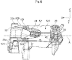
- the figures 1 to 17 illustrate a first embodiment of an optical assembly 1 according to the invention.
- the optical assembly is arranged so as to produce a cut-off beam which is complementary to a dipped beam and forms an upper part of a main beam.
- the optical assembly 1 has a longitudinal axis X extending in a direction from upstream to downstream of the first optical part 2
- axes are also shown in the figures.
- One of these axes is a second transverse axis Y, in particular substantially perpendicular to the longitudinal axis X and extending from the left to the right of the figures.
- a third transverse axis Z in particular substantially perpendicular, to the longitudinal axis X and to the transverse axis Y.
- the third axis Z extends, here, from the bottom to the top of the figures.
- the optical assembly 1 is arranged so that the longitudinal axis X is substantially parallel to the longitudinal axis of a vehicle (not shown) equipped with said optical assembly. Moreover, with this arrangement of the optical assembly 1, the second axis Y is substantially perpendicular to the longitudinal axis X and belongs to a horizontal plane containing said axis X. As for the third axis Z, this is substantially perpendicular to the other two axes and extending in a vertical direction.
- the Y and Z axes are thus called respectively the transverse axis Y and the vertical axis Z.
- the three axes X, Y and Z here form an orthogonal reference.
- the first optical part 2 comprises a plurality of light guides 20.
- Each light guide 20 extends along the longitudinal axis X and comprises an input diopter 21 and an output 22.
- a light source (not shown on them figure 2 and 3 ) is placed in front of each input dioptre 21.
- the light guides 20 are arranged so that the light rays from the light sources propagate inside the guides by total internal reflection along the longitudinal axis X, from upstream to downstream, i.e. i.e. in the direction of the entrance dioptre 21 towards the exit 22.
- the first optical part 2 comprises a common output 23 located downstream of the outputs 22 of the light guides.
- the common output 23 here forms a front face of the first optical part 2 through which the light rays come out of said first part 2.
- the first optical part 2 further comprises a first face 24 extending between the common output 23 and the outputs 22 of the light guides 20.
- the first face 24 forms part of an upper face of the first optical part 1.
- the first face 24 is delimited downstream by a cutting edge 25. More precisely, in the In the example shown, the first face 24 and the common exit 23 join the cut edge 25.
- the cutting edge 25 comprises a first horizontal portion 251, a second horizontal portion 252, and an intermediate portion 253 connecting the first horizontal portion 251 to the second horizontal portion 253.
- the first horizontal portion 251 is located higher than the first second horizontal portion 252.
- the intermediate portion 253 is inclined by a value between 15° and 45° relative to the horizontal.
- the optical assembly 1 is designed so as to generate a beam having a cut-off line and which is complementary to a passing beam.
- the cut-off beam generated by the optical assembly 1 constitutes the upper part of a driving beam.
- the projection of the first horizontal portion 251 forms a first part of the cutoff line located below the horizon.
- the projection of the second horizontal portion 252 forms a second part of the cut line located above the horizon.
- the projection of the intermediate portion 253 forms part of the middle of the cut line, inclined with respect to the horizon.
- the first optical part 2 has a main axis A parallel to the longitudinal axis X and passing through the middle of the intermediate portion 253 of the cut edge 25.
- FIG. 5 An example of making the reflective material is illustrated in the figure 5 , 6 and 7 .
- the reflecting material is formed by a reflection member 5 separate from the first optical part 2 and having a first face.
- the reflection member 5 is arranged on the first optical part 2 so that the first face of the reflection member 5 is opposite the first face 24 of the first optical part 2 .
- Reflection member 5 is made up of a reflective plate 51 and a support plate 52. In another embodiment, the reflection member can be made in one piece.
- the reflective plate 51 is here a thin metallic blade and delimited downstream by a downstream edge 550.
- the reflective plate 51 has a first face 511 on one side and a second reflective face 513 on the other side.
- the first face 511 of the reflecting plate 51 forms the first face of the reflection member 5.
- the support plate 52 is used to support said plate 51 and to keep it fixed to the first optical part 2.
- the reflective plate 51 is secured to support plate 52 by gluing, welding or screwing.
- the support plate 52 is hollowed out so as to leave the first face 24 exposed. In this way, when the reflecting plate 51 is placed on the support plate 52, the first face 511 of the reflecting plate 51 faces the first face 24 of the first optical part 2.
- the reflective plate 51 extends from the cut-off edge 25 downstream.
- the downstream edge 550 of the reflective plate 51 is perfectly aligned with the cut-off edge 25.
- the front edge 550 is positioned neither in front nor behind with respect to the cut-off edge 25.
- the profile of the downstream edge 550 is identical to the profile of the cut-off edge 25 which here is curved in the direction of the entrance diopters 21.
- the cutting edge 25 has a step formed by the intermediate portion 253.
- the reflective plate 51 and the support plate 52 are made, for example by bending, so that the downstream edge 550 has the same profile as the cutting edge 25, that is to say with two horizontal portions 551, 552 interconnected by an inclined linear portion 553, as shown in figure 5 .
- Reflector 5 including reflective plate 51 and support plate 52, also has axis A as the main axis. This virtually divides the optical assembly 1 into two parts including a first part 4 located to the left of the main axis A and a second part 6 located to the right of said main axis A.
- the terms "left » « right » designate respectively the left of the figure 4 and the right of the figure 4 .
- the reflective plate 51 is in direct contact with the whole of the cut-off edge 25. More specifically, the first face 511 of the reflective plate 51 has a downstream central portion 510. The direct contact of the reflective plate 51 with the whole of the cutting edge 25 is made with this downstream central portion 510.
- the central portion 510 is in direct contact with the first optical part 2 only on the cut-off edge 25. Specifically, the portions of the downstream edge 510 are in contact with the corresponding portions of the cut-off edge 25.
- the first horizontal portion 551 of the downstream edge 550 is in direct contact with the first horizontal portion 251 of the cut-off edge 25, the second horizontal portion 552 of the downstream edge 550 is in direct contact with the second horizontal portion 252 of the edge cutoff 25, and the inclined linear portion 553 is in direct contact with the intermediate portion 253 of the cutoff edge.
- This direct contact is obtained by means of the pressing members 26 and 29 located respectively at the front and the rear of the first optical part 2.
- These pressing members are called hereinafter the front pressing member 26 and the rear tackle member 29 and details relating thereto are illustrated in the figures 6 to 14 .
- the plating members 26 and 29 are made in one piece with the first optical part 2.
- the first optical part 2 comprises two identical front plating members 26 which are arranged respectively on a left side and on a right side of the first optical part 2.
- front pressing members 26 have the same shape regardless of their location, only the front pressing member located to the right of the main axis A, referenced 26a, will be described. This description applies in the same way to the pressing member located to the left of the main axis A, referenced 26b in the figures. If there are any differences between the two sides, these will be addressed. The same applies to the elements in connection with the front tackle components.
- the front plating member 26a cooperates with the support plate 52 and the reflecting plate 51.
- the support plate 51 comprises two lateral arms 520 extending from upstream to downstream and arranged symmetrically with respect to the main axis A.
- Each lateral arm 520 comprises a free end 521.
- the reflective plate 51 may comprise two side members 512 extending on either side of a central portion 510 comprising the downstream edge 550.
- the side members 512 of the reflective plate 51 overlap with the side arms 520 of the support plate 52, and in particular at the level of the free end 521.
- the side arm 520 of the support plate 52 and the side member 512 of the reflective plate 51 are in connection with the front right tackle member 26.
- the front plating member 26a may comprise a first portion 261 extending along the vertical axis Z and a second portion 262 extending along the longitudinal axis X from one end of the first portion 261 upstream.
- the front pressing member 26 thus has the shape of a hook.
- the front plating member 26a is in contact with the reflection member 5. Specifically, when the first optical part 2 and the reflection member 5 are assembled together, the reflection member 5 is in contact with the second portion 262 so as to block the movement of the reflection member 5 along the Z axis.
- the lower face 263 of the second portion 262 bears against the second reflecting face 513 of the reflecting plate 51. This contact therefore prevents the reflecting member 5 from moving vertically upwards.
- the front pressing member 26a serves as a stop to block the movement of the reflection member 5 along the Z axis.
- the front pressing member is also called the vertical stop member 26a.
- the end 521 of the reflection member can be located at a distance from the first portion 261 so as to delimit a space along the longitudinal axis X. This space forms an assembly clearance in the longitudinal direction in order to facilitate the mounting of the reflection member 5 on the first optical part.
- the front pressing member 26a ensures direct contact between the cutting edge 25 and the downstream edge 510 of the reflective plate 51.
- the front pressing member 26a is configured so that the lower face 263 of the second portion 262 is parallel to a horizontal plane H1 passing through the second horizontal portion 252 of the cut-off edge 25 and so that the distance di between the lower face 263 and the plane H1 is equal to or slightly less than the total thickness of the reflection member 5.
- the distance d1 is illustrated on the figure 9 .
- the left front pressing member 26b also comprises a first portion and a second portion identical to those of the right front pressing member 26a. Said portions therefore bear the same references.
- the left front pressing member 26b is arranged so that the lower face 263 of the second portion 262 is parallel to a horizontal plane H2 passing through the first horizontal portion 251 of the cutting edge 25 and that the distance between the lower face 263 and the plane H2 is equal to or slightly less than the total thickness of the reflection member 5.
- the left front pressing member 26b is slightly offset upwards with respect to the right front pressing member 26a. This offset corresponds to the distance between the H1 plane and the H2 plane.
- the total thickness of the reflection member is the sum of the thickness e of the supporting plate 52 and the thickness of the reflecting plate 51. Since the reflecting plate 51 is very thin, the thickness of said plate is not referenced in the figures.
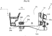
- the first optical part 2 can also comprise two lateral abutment members 27 arranged so as to block the movement of the reflection member 5 along the transverse axis Y.
- the lateral abutment members 27 are identical and arranged symmetrically with respect to the main axis A. For this reason, only the lateral abutment member located to the right of the main axis A, referenced 27a, is described below. after. The description applies in the same way to the other organ not described. The same applies to the elements in connection with the lateral abutment members. Of course, the differences between the two sides will also be described.
- the lateral abutment member can be formed by a pin 27a projecting relative to the first face 24 of the first optical part 2.
- the pin 27a has a circular section.
- the pin 27a and the first optical part 2 are made in one piece.
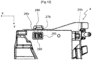
- the reflection member 5 comprises a slot 28a extending along the longitudinal axis X.
- the slot 28a is formed by a first opening 514 made in the reflecting plate 51 and by a second opening 524 made in the support plate 52.
- Said first and second openings 514 and 524 have the same dimensions and are positioned at the same place.
- the first and second openings 514 and 524 overlap and are aligned so as to form the slot 28a.
- the width of the slot 28a, measured along the transverse axis Y is equal to the diameter of the pin 27a.
- the pin 27a and the slot 28a are arranged so as to allow sliding of the pin 27 in the slot 28a along the longitudinal axis X in the direction from downstream to upstream until this that the pin 27 is in abutment against an upstream transverse edge 281 so as to block the movement along the longitudinal axis X of the reflection member in the direction from upstream to downstream.
- Such a displacement is represented by an arrow F1 illustrated on the figure 10 .
- the upstream transverse edge 281 extends substantially parallel to the transverse axis Y and it is located behind the slot 28a.
- the pin 27a once engaged in the slot 28a, blocks both the movement along the longitudinal axis X and the movement along the transverse axis Y of the reflection member 5.
- the lateral abutment member 27 is also formed by a pin of circular section referenced 27b. Said pin 27b is inserted into a slot 28b. However, unlike the straight part 6, the pin 27b is only in abutment against the upstream transverse edge 281 of the slot 28b. The pin 27b is not in abutment against the longitudinal edges 280 of the slot 28b, because the width of the slot 28b is greater than the diameter of the pin 27b. This creates a play in the transverse direction facilitating the mounting of the reflection member.
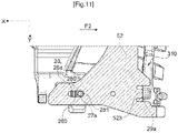
- the first optical part 2 can comprise two identical rear plating members 29 which are also arranged respectively on the left part and on the right part of the first optical part.
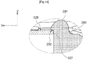
- the rear right tackle member 29a is illustrated in the figure 13 and 14 .
- the rear right tackle member 29a may comprise a straight portion 290 and a rounded portion 291 extending from a free end of said straight portion 290 downstream.
- the rounded portion 291 and the straight portion 290 are arranged so as to delimit a space for receiving an elastic tab 523.
- the support plate 52 may comprise at least one elastic tab 523 located at the rear of said plate 52.
- the support plate comprises two elastic tabs 523 located at the rear and respectively on one left side and on a right side. Only the right tab is described below.
- the elastic tongue 523 is in contact with the rear pressing member 29a while being prestressed, so as to block the movement along the longitudinal axis X of the reflection member 5 in the direction from downstream to upstream. .
- Such a displacement is represented by an arrow F2 illustrated on the figure 11 .
- the free end 527 of the tab 528 is in abutment under stress against the straight portion 290 of the rear pressing member 29a.
- the tab 523 also abuts against the rounded portion 291 so as to block the movement of the reflection member 5 along the vertical axis Z.
- an upper face 528 of the tongue 523 is in contact with a lower face 292 of the rounded portion 291.
- the support plate 52 comprises two tabs 525 and 526 arranged on either side of the tab 523. These two tabs are placed on an upper face 310 of a promontory 30 located downstream of the entrance diopters 21.
- the promontory 30 is formed, here, by a rectangular block extending substantially parallel to the transverse axis Y.
- the upper face 310 of the promontory 30 is flat and substantially parallel to a plane containing the X and Y axes.
- the promontory 30 is made in one piece with the first optical part 2.
- the contact between the tab 523 and the rounded portion 291 results from the fact that the distance, measured along the vertical axis Z, between the upper face 310 and the lower face 292 of the rounded portion 291 is equal or slightly less than the thickness of the reflection member 5.
- the support plate 52 With the support plate 52 and the rear plating member 29a as configured, the support plate 52 is assembled to the first optical part 2 by clipping.
- the rear pressing member 29a therefore forms an abutment member blocking both the vertical displacement and the longitudinal displacement of the reflection member 5.
- the rear pressing member 29 ensures direct contact between the cut-off edge 25 and the downstream edge 510 of the reflective plate 51.
- the rear pressing member 29a ensures direct contact between the second horizontal portion 252 of the cut-off edge 25 and the corresponding portion of the downstream edge 510 of the plate.
- the first optical part 2 is arranged so that the distance, measured along the vertical axis Z, between the upper face 310 and the lower face 292 of the rounded portion 291 is equal to or slightly less than the thickness of the reflection member 5, and so that the upper face 310 of the promontory 30a of the straight part 6 is contained in the horizontal plane H1 passing through the second horizontal portion 252 of the cutting edge 25.
- the rear left plating member 29b also comprises a straight portion and a rounded portion which are identical to those of the rear right plating member 29a. Said portions are therefore designated by the same references.
- the same conditions must be fulfilled.
- the distance, measured along the vertical axis Z, between the upper face 310 of the left promontory 30b and the lower face 292 of the rounded portion 291 of the left rear tackle member 29b is equal to or slightly less than the thickness of the reflection member 5.
- the upper face 310 of the left promontory 30b is in the horizontal plane H2 passing through the first horizontal portion 252 of the cutting edge 25.
- the left promontory 30b is higher than the right promontory 30a.
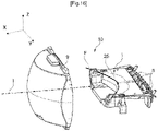
- the optical assembly 1 described in the preceding paragraphs is part of a light module 10 as illustrated in the figure 16 .
- the light module 10 comprises the optical assembly 1 and a convergent lens 9.
- the convergent lens 9 is arranged so that its focal point F is located near the cut-off edge 25 and the downstream edge 510.
- the light module further comprises light sources 8.
- Each light source 8 is arranged opposite each input dioptre 21.
- the light guides 20 are arranged so as to reflect light rays coming from the light sources 8 towards elementary outputs 22.
- the light module 10 is capable of generating a beam having a cut-off line along an optical axis I.
- the optical axis I is substantially parallel to the main axis A.
- the light source 8 emits first light rays R1 which, after being reflected inside the light guide, are sent to the cutting edge 25.
- the first light rays R1 are parallel to the optical axis I on leaving the converging lens 9.
- the projection of these first light rays R1 forms the cut-off line of the beam generated by the light module 10.
- the light source 8 emits second light rays R2 which, after being reflected inside the light guide 20, pass below the cutting edge 25.
- the lens 9 and the optical assembly are arranged so as to so that the second light rays R2 are sent towards the converging lens 9. As these second rays pass under the cutting edge, they leave said lens along a first axis secant to the optical axis I and towards the same first side of a horizontal plane passing through this optical axis, here upwards.
- the light source 8 emits third light rays R3 which, after being reflected inside the light guide 20, reach the first face 24 of the first part 2, which sends them back towards the converging lens 9. They come out then from said lens along a second secant axis to the optical axis I and also towards the first side of the horizontal plane passing through this optical axis, here upwards.
- the first face 24 of the first optical part therefore forms a bender for the beam emitted by the light source 8.
- the projection of the second and third rays R2 and R3 forms the part situated above the cut-off line of the beam projected by the lens 9.
- the beam obtained is a beam with a cut-off line, also called cut-off beam.
- cut-off beam For example, as shown, it may be an upper portion of a high beam.
- the reflection member 5 does not have an optical function with respect to the first optical part 2.
- the reflection member 5 has an optical function for an assembly 20 for generating rays of light placed above the optical assembly 1 to generate a passing beam.
- Said passing beam has on the one hand a cut-off line identical to the cut-off line of the beam generated by the optical assembly 1, and on the other hand forms a shape complementary to that of the beam generated by the optical assembly 1 at the level of this cut line.
- the light ray generation assembly 20 is schematically illustrated in the figure 16 .
- the reflection member 5 is arranged with the generation assembly 20 so that fourth rays R4, coming from said generation assembly 20, and passing through the downstream edge 550, are parallel to the optical axis I leaving the converging lens 9.
- the projection of these fourth rays R4 forms the cut-off line of the dipped beam.
- the arrangement of the reflection member 5 with the generation assembly 20 is made in such a way that fifth rays R5, coming from said generation assembly 20 and reaching the reflecting face 513 of the reflecting plate 51, are reflected towards the converging lens 9.
- the fifth rays R5 leave said lens along an axis secant to the optical axis I and towards a second side of the horizontal plane passing through this optical axis, here downwards. Said fifth rays R5 are thus projected below the cut-off line.
- the reflecting plate of the reflection member 5 therefore forms a bender for the light beam emerging from the assembly 20.
- the dipped beam generated by the generation assembly 20 forms with the cut-off beam generated by the optical assembly 1 a driving beam.
- the cut-off edge 25 forming the cut-off line of the cut-off beam generated by the optical assembly 1 is in direct contact with the downstream edge 550 forming the cut-off line of the dipped beam generated by the generation assembly 20 , the cut-off lines of said beams merge on the projection, which allows a better junction between said beams.
- the cut-off beam generated by the optical assembly 1 has no black band at the level of the cut-off line.
- the driving beam obtained from this combination is free of a black transition line formed by the black band, which therefore makes it possible to improve the optical performance of the driving beam.
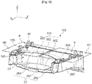
- the figures 18 to 25 illustrate a second embodiment of the optical assembly 100 according to the invention.
- the optical assembly 100 is also designed to generate a cut-off beam complementary to a passing beam and forming the upper part of a driving beam.
- the optical assembly 100 comprises a first optical part 200 and a reflection member 50 arranged on said first optical part 200.
- the reflection member 50 also consists of a support plate 58 and a reflecting plate 57.
- the first optical part 200 is similar to the first optical part 2 of the first embodiment.
- the first optical part 200 comprises guides extending along the longitudinal axis X.
- Each of the guides comprises an input dioptre and an elementary output.
- a common output, forming the front face 23 of the first optical part 200, is arranged downstream of the elementary outputs.
- the upper edge of the front face 23 of the first optical part forms the cut-off edge 25.
- the latter is identical to that presented in the first embodiment, that is to say that it comprises a first horizontal portion 251, a second horizontal portion 252, and an intermediate portion 253 connecting the first horizontal portion 251 to the second horizontal portion 253.
- the plate reflective 57 is delimited by a downstream edge 550 which is in direct edge-to-edge contact with the cut-off edge 25 and perfectly aligned with said edge 25 seen from above.
- the optical assembly 200 has a main axis A passing through the middle of the intermediate portion 253 and dividing the optical assembly 200 into a left part 4 and a right part 6.
- the terms "left “, “right” or “right” correspond respectively to the left and to the right of the figure 18 .
- the first optical part 200 also comprises front 2600, rear 2900 pressing members and lateral abutment members 2800.
- the front 2600, rear 2900 pressing members and lateral abutment members 2800 on the one hand and the first part optical 200 on the other hand are formed in a single piece.
- the pressing and lateral abutment members are two in number. In the same pair, one is located on the right side 6 and the other on the left side 4.
- the part numbers on the right side end with the letter "a” while the part numbers on the left side by the letter “b”.
- the support plate 58 is in contact with the front and rear pressing members and the lateral abutment members.
- the front tackle members 2600 having the same shape, only the left member 2600a is described below. Unless otherwise indicated, the description applies equally to the other member 2600b. The differences between these two organs will be mentioned.
- the front right tackle member 2600a may comprise a first portion 2610 extending substantially along the vertical axis Z and a second portion 2620 extending from one end of the first portion 2610 towards the 'upstream.
- the pressing member 2600a thus has the shape of a hook.
- the support plate 58 comprises a central portion on which the reflective plate 57 is placed and two lateral portions arranged on either side of the central portion.
- the side portions each include an elongated arm 540 or 560 extending downstream.
- the front plating member 2900a is in contact with an elongated arm 560 of the support plate 58.
- a lower face 2630 of the second portion 2620 is in contact with the upper face 530 of the support plate 58 at the level of the arm 560. This contact prevents the movement of the reflection member 50 along the vertical axis Z in the direction of distance from the first optical part 200.
- a downstream end 5121 of the elongated arm 560 can also be in contact with a rear face 2611 of the first portion 2610, which blocks the movement of the reflection member 50 along the longitudinal axis X and in the direction from upstream to downstream as illustrated by the arrow F1.
- the front pressing member 2600a therefore forms an abutment blocking both the vertical displacement and the longitudinal displacement of the reflection member 50.
- the front pressing members 2900 are arranged so as to ensure direct contact between the downstream edge 510 of the reflection member 50 with the cut-off edge 25.
- the member front left plating 2600a is arranged so that the distance between the lower face 2630 of the first portion 2620 and a plane H1 is equal to or slightly less than the thickness of the reflection member 50.
- the plane H1, illustrated on the figure 18 is a horizontal plane passing through the second horizontal portion 252 of the first optical part 200.
- the plane H1 of the second example is substantially identical to that of the first example.
- the right front pressing member 2600b comprises a second portion whose lower face is located at a distance from a plane H2 also illustrated on the figure 18 . This distance is equal to or slightly less than the thickness of the reflection member.
- the plane H2 is a horizontal plane passing through the first straight portion 251 of the cutoff edge.
- the plane H2 of the second example is substantially identical to that of the first example.
- the left front pressing member 2600b is offset upwards with respect to the right front pressing member 2600a. This offset corresponds to the distance between the H1 plane and the H2 plane.
- the lateral abutment members are not identical. They will therefore be described individually below.
- the lateral abutment member 2800a can be arranged on one side of the first optical part, here the right side.
- said member 2800a is formed by a projection extending from the upper face of the first optical part 200.
- the support plate 58 includes a recess 580 located at the same location as the right side abutment member 2800a.
- the recess 580 is also called a notch.
- an edge 581 of the recess 580 is in contact with an internal side face 2810 of the member 2800a so as to block the movement of the reflection member 50 along the transverse axis Y in the direction from left to right illustrated by the arrow F3.
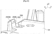
- the left lateral abutment member 2800b is formed by a block projecting from the upper face of the first optical part 200.
- Said projecting block has a thickness greater than that of the projection forming the right side abutment member 2800a.
- Support plate 58 includes a flexible tab 582 extending from a left side edge 584 of support plate 58.
- Flexible tab 582 is located opposite left side abutment member 2800b.
- the width of the flexible tab 582 is substantially equal to the width of the member 2800b.
- the flexible tongue 582 bears against an internal side face 2820 of the abutment member 2800b while being curved upwards .
- the left stop member 2800b is also called the support member.
- Pressing the tab on the abutment member 2800b makes it possible to block the lateral movement of the support plate 58, therefore of the reflection member 50, in the direction from right to left as illustrated by the arrow F4.
- such pressing of the tongue 582 against the projecting block 2800b generates a force pressing the recess 580 against the projection 2800a.
- the deformability of the flexible tongue 582 makes it possible to absorb the swelling of the middle of the reflection member 50 when the latter is mounted on the first optical part 200. In the event of swelling of the reflection part 50, it suffices to press on the inflated part of said piece 50 to lay it flat. The flattening of the reflector 50 therefore causes the flexible tongue 582 to bend further.
- the right rear pressing member 2900a can comprise a straight portion 2910 and a rounded portion 2920.
- the latter here has a substantially triangular section.
- the rounded portion 2920 extends from an upper end of the straight portion 2910 downstream.
- the support plate 58 comprises a curved rear portion 585 upwards, that is to say opposite the first face of the first optical part 200.
- a rear end 5850 of the curved rear portion 585 can be in contact with the rear pressing member 2900a so as to block the movement of the reflection member 50 along the vertical axis Z in the direction of distance from the first optical part 200.
- the rear end 5850 of the curved portion 585 is in contact with the lower face 2930 of the rounded portion 2920.
- the rear pressing member 2900a also serves as a stop to block the movement of the reflection member 5 along the Z axis.
- the pressing member is also called the vertical stop member 2900a.
- the support plate 58 is placed on a protrusion 250 which is integral with the first optical part 200.
- the protrusion 250 is located downstream of the rear plating member 2900b and includes a planar upper face 251 which is in contact with the support plate 58.
- the protrusion 250 and the rear pressing member 2900b are arranged so that the upper face 251 of the protrusion 250 belongs to the plane H and in such a way that the distance, measured along the vertical axis Z, between the lower face 2930 of the rounded portion 2920 and the plane H1 is substantially equal to the height h of the curved portion 585.
- the same conditions apply analogously to the rear left plating member 2900b and to the protrusion left (not visible in the figures).
- the upper face of the left protrusion must belong to the H2 plane.
- the distance between the lower face of the rounded portion of the left member 2900b and the plane H2 must be substantially equal to the height h of the curved portion 585.
- the left protrusion is higher than the 250 protrusion on the right side.
- the height difference corresponds to the distance between the H1 and H2 planes.
- the optical assembly 100 as described can form part of the light module 10 described above by replacing the optical assembly 1 according to the first embodiment.
Landscapes
- Engineering & Computer Science (AREA)
- General Engineering & Computer Science (AREA)
- Physics & Mathematics (AREA)
- Microelectronics & Electronic Packaging (AREA)
- Optics & Photonics (AREA)
- Non-Portable Lighting Devices Or Systems Thereof (AREA)
- Optical Elements Other Than Lenses (AREA)
- Re-Forming, After-Treatment, Cutting And Transporting Of Glass Products (AREA)
Claims (12)
- Optische Einheit (1, 100), die dazu bestimmt ist, ein Bündel mit einer Hell-Dunkel-Grenze zu bilden, wobei die optische Einheit (1, 100) enthält:- ein erstes optisches Bauteil (2, 200) aus transparentem Material, das enthält:o Lichtleiter (20), die je ein Eingangsdiopter (21) und einen Elementarausgang (22) enthalten;o einen gemeinsamen Ausgang (23), der sich stromabwärts hinter den Elementarausgängen (22) befindet;o eine erste Seite (24), die sich zwischen den Elementarausgängen (22) und dem gemeinsamen Ausgang (23) erstreckt, wobei diese erste Seite (24) stromabwärts durch eine Hell-Dunkel-Kante (25) begrenzt wird;- ein reflektierendes Material (5; 50) getrennt vom Material des ersten optischen Bauteils (2; 200) und gegenüber der ersten Seite (24) des ersten optischen Bauteils (2; 200) angeordnet, wobei das reflektierende Material (5; 50) sich von der Hell-Dunkel-Kante (25) zu den Elementarausgängen (22) erstreckt;wobei das reflektierende Material (5; 50) und das erste optische Bauteil (2) so eingerichtet sind, dass sie aneinander ohne zusätzliches Bauteil festhalten, und dass das reflektierende Material (5; 50) in direktem Kontakt mit der Hell-Dunkel-Kante (25) ist;- wobei das reflektierende Material von einem Reflexionsorgan (5; 50) getrennt vom ersten optischen Bauteil (2; 200) gebildet wird;- wobei das Reflexionsorgan (5; 50) eine erste Seite (511) aufweist,wobei das erste optische Bauteil (2; 200) mindestens ein Andrückorgan (26, 29; 2600, 2900) enthält, das so eingerichtet ist, dass die erste Seite (511) des Reflexionsorgans (5; 50) in direktem Kontakt mit der Hell-Dunkel-Kante (25) ist, wobei das erste optische Bauteil (2; 200) und das Andrückorgan (26, 29; 2600, 2900) in einem einzigen einstückigen Bauteil geformt sind;
dadurch gekennzeichnet, dass:- die erste Seite des Reflexionsorgans (5; 50) einen stromabwärtigen zentralen Abschnitt (510) aufweist, wobei der direkte Kontakt mit diesem stromabwärtigen zentralen Abschnitt (510) hergestellt wird, und dieser stromabwärtige zentrale Abschnitt (510) nur auf der Hell-Dunkel-Kante (25) in direktem Kontakt mit dem ersten optischen Bauteil (2; 200) ist, der stromabwärtige zentrale Abschnitt (510) stromabwärts durch einen stromabwärtigen Rand (550) begrenzt wird, wobei der direkte Kontakt zwischen dem Reflexionsorgan (5; 50) und dem ersten optischen Bauteil (2; 200) durch den direkten Kontakt des stromabwärtigen Rands (550) mit der Gesamtheit der Hell-Dunkel-Kante (25) geformt wird. - Optische Einheit (1; 100) nach Anspruch 1, wobei das Reflexionsorgan (5; 50) auf der einen Seite die erste Seite (511) und auf der anderen Seite eine zweite Seite (513) aufweist, wobei die zweite Seite (513) reflektierend ist.
- Optische Einheit (1; 100) nach Anspruch 1 oder Anspruch 2, wobei das erste optische Bauteil (2; 200) aufweist:- eine Längsachse (X), die sich gemäß einer Richtung von stromaufwärts nach stromabwärts des ersten optischen Bauteils (2; 200) erstreckt,- eine zweite Achse (Y), die sich von einer Seite der Hell-Dunkel-Kante (25) zur anderen und orthogonal zur Längsachse (X) erstreckt, und- eine dritte Achse (Z) orthogonal zur Längsachse (X) und zur zweiten Achse (Y), wobei das erste optische Bauteil (2; 200) Anschlagorgane (26, 27, 29; 2600, 2800, 2900) in Kontakt mit Anschlägen (512, 28, 523; 540, 560, 581, 585) des Reflexionsorgans (5; 50) enthält, um die Verschiebung des Reflexionsorgans (5; 50) bezüglich des ersten optischen Bauteils (2; 200) gemäß mindestens einer dieser Achsen (X, Y, Z) zu blockieren.
- Optische Einheit (1; 100) nach Anspruch 3, wobei mindestens eines der Anschlagorgane (26, 27, 29; 2600, 2800, 2900) so eingerichtet ist, dass es das Reflexionsorgan (5; 50) gegen die Hell-Dunkel-Kante (25) andrückt.
- Optische Einheit (1; 100) nach Anspruch 1 bis 4, wobei das Reflexionsorgan (5; 50) mindestens einen elastischen Abschnitt (523; 582) in Spannung gegen einen entsprechenden Auflageabschnitt (29; 2800b) des ersten optischen Bauteils (2; 200) enthält, um eine Kraft zu erzeugen, die mindestens einen Anschlag (281; 581) des Reflexionsorgans (5; 50) gegen das entsprechende Anschlagorgan (29; 2800a) des ersten optischen Bauteils (2; 200) andrückt.
- Optische Einheit (1; 100) nach einem der Ansprüche 1 bis 5, wobei das Reflexionsorgan (5; 50) von einer oder mehreren Platten (51, 52; 57, 58) gebildet wird.
- Optische Einheit (1; 100) nach Anspruch 6, wobei das Reflexionsorgan (5; 50) zwei Teile enthält: eine reflektierende Platte (51; 57) und eine Tragplatte (52; 58), wobei die Tragplatte (52; 58) vom ersten optischen Bauteil (2; 200) getragen wird und die reflektierende Platte (51; 57) trägt, wobei der direkte Kontakt im Bereich der reflektierenden Platte (51; 57) hergestellt wird.
- Optische Einheit (1; 100) nach Anspruch 6 oder Anspruch 7 in Kombination mit Anspruch 5, wobei die Platte oder die Tragplatte (52; 58) elastische Zungen (523; 582) enthält, die die elastischen Abschnitte bilden.
- Optische Einheit (100) nach Anspruch 8, wobei:- der Auflageabschnitt (29; 2800b) von einem vorstehenden Block (2800b) gebildet wird, der auf einer Seite des ersten optischen Bauteils (200) angeordnet ist, und- der elastische Abschnitt von einer elastischen Zunge (582) gebildet wird, die sich gegenüber dem vorstehenden Block (2800b) befindet, wobei die elastische Zunge (582) unter Spannung gegen den vorstehenden Block (2800b) in Auflage ist, indem sie entgegengesetzt zur ersten Seite des ersten optischen Bauteils (200) gekrümmt ist.
- Kraftfahrzeug-Leuchtmodul (10), wobei das Modul geeignet ist, ein Lichtbündel gemäß der optischen Achse zu bilden und enthält:- eine optische Einheit (1; 100) nach einem der vorhergehenden Ansprüche;- Lichtquellen (8), die je gegenüber jedem Eingangsdiopter (21) angeordnet sind; wobei die Lichtleiter (20) so eingerichtet sind, dass sie von den Lichtquellen (8) stammende Lichtstrahlen durch eine oder mehrere Reflexionen zu den Elementarausgängen (22) leiten; und- eine konvergierende Linse (9), deren Brennebene in der Nähe der Hell-Dunkel-Kante (25) des ersten optischen Bauteils (2) eingerichtet ist;wobei die optische Einheit (1; 100) so eingerichtet ist, dass die erste Seite des ersten optischen Bauteils (3, 5, 51) eine Biegefläche für die von diesen Elementarausgängen kommenden Strahlen bildet, damit die aus der Linse (9) austretenden Strahlen ein erstes Bündel bilden, das eine Hell-Dunkel-Grenze aufweist, die das Abbild der Hell-Dunkel-Kante (25) ist.
- Leuchtmodul (10) nach Anspruch 10, das außerdem eine Einheit zur Erzeugung von Lichtstrahlen (20) enthält, wobei das erste optische Bauteil (2; 200) auf einer Seite des Reflexionsorgans (5; 50) eingerichtet ist und die Erzeugungseinheit (20) Lichtstrahlen auf der anderen Seite des Reflexionsorgans (5; 50) emittiert, damit das Reflexionsorgan (5; 50) eine Biegefläche für die von der Erzeugungseinheit (20) kommenden Strahlen bildet, um ein zweites Bündel zu bilden, das einerseits eine Hell-Dunkel-Grenze im Wesentlichen gleich derjenigen des ersten Bündels und andererseits eine Form komplementär zu derjenigen des ersten Bündels im Bereich dieser Hell-Dunkel-Grenze aufweist.
- Leuchtmodul (10) nach Anspruch 11, wobei das zweite Bündel ein Abblendlichtbündel ist und das erste Bündel ein oberer Teil eines Fernlichtbündels ist, so dass die zwei Bündel zusammen ein Fernlichtbündel bilden.
Applications Claiming Priority (1)
| Application Number | Priority Date | Filing Date | Title |
|---|---|---|---|
| FR1903917A FR3095028B1 (fr) | 2019-04-12 | 2019-04-12 | Ensemble optique apte à former un faisceau lumineux à coupure |
Publications (2)
| Publication Number | Publication Date |
|---|---|
| EP3722663A1 EP3722663A1 (de) | 2020-10-14 |
| EP3722663B1 true EP3722663B1 (de) | 2022-12-14 |
Family
ID=68138230
Family Applications (1)
| Application Number | Title | Priority Date | Filing Date |
|---|---|---|---|
| EP20164742.7A Active EP3722663B1 (de) | 2019-04-12 | 2020-03-20 | Optische einheit, die einen lichtstrahl mit hell-dunkel-grenze erzeugen kann |
Country Status (3)
| Country | Link |
|---|---|
| EP (1) | EP3722663B1 (de) |
| CN (1) | CN111810913B (de) |
| FR (1) | FR3095028B1 (de) |
Families Citing this family (1)
| Publication number | Priority date | Publication date | Assignee | Title |
|---|---|---|---|---|
| CN117968008B (zh) * | 2024-03-28 | 2024-06-21 | 领为视觉智能科技(宁波)有限公司 | 一种组合式汽车照明模组和汽车 |
Family Cites Families (8)
| Publication number | Priority date | Publication date | Assignee | Title |
|---|---|---|---|---|
| FR3019267A1 (fr) * | 2014-04-01 | 2015-10-02 | Valeo Vision | Systeme d'eclairage a longue portee pour vehicule automobile |
| FR3026461B1 (fr) * | 2014-09-30 | 2019-04-05 | Valeo Vision | Module lumineux pour l'eclairage et/ou la signalisation d'un vehicule automobile |
| FR3033621B1 (fr) * | 2015-03-13 | 2017-04-21 | Valeo Iluminacion Sa | Dispositif lumineux a guides optiques |
| FR3042845B1 (fr) * | 2015-10-23 | 2019-11-29 | Valeo Vision | Dispositif lumineux a guides optiques |
| DE102015224745B4 (de) * | 2015-12-09 | 2017-11-16 | Automotive Lighting Reutlingen Gmbh | Kraftfahrzeugscheinwerfer mit einer Grundlichtbaugruppe und einer Fernlichtbaugruppe |
| JP2017212037A (ja) * | 2016-05-23 | 2017-11-30 | スタンレー電気株式会社 | 車両用前照灯 |
| KR101907372B1 (ko) * | 2017-04-26 | 2018-10-12 | 현대모비스 주식회사 | 헤드램프 장치 |
| DE102017110876A1 (de) * | 2017-05-18 | 2018-11-22 | Automotive Lighting Reutlingen Gmbh | Lichtmodul eines Kraftfahrzeugscheinwerfers und Kraftfahrzeugscheinwerfer mit einem solchen Lichtmodul |
-
2019
- 2019-04-12 FR FR1903917A patent/FR3095028B1/fr not_active Expired - Fee Related
-
2020
- 2020-03-20 EP EP20164742.7A patent/EP3722663B1/de active Active
- 2020-04-10 CN CN202010279654.8A patent/CN111810913B/zh active Active
Also Published As
| Publication number | Publication date |
|---|---|
| CN111810913A (zh) | 2020-10-23 |
| CN111810913B (zh) | 2025-02-21 |
| FR3095028B1 (fr) | 2022-08-05 |
| EP3722663A1 (de) | 2020-10-14 |
| FR3095028A1 (fr) | 2020-10-16 |
Similar Documents
| Publication | Publication Date | Title |
|---|---|---|
| EP4264122B1 (de) | Beleuchtungsvorrichtung für ein kfz | |
| EP4235024B1 (de) | Leuchtvorrichtung, die die beleuchteten flächen von mindestens zwei kollektoren abbildet | |
| EP3167226B1 (de) | Beleuchtungsmodul für ein kraftfahrzeug | |
| EP2422130B1 (de) | Fahrzeugscheinwerfer mit einer verbesserten fernlicht | |
| EP4264120A1 (de) | Kraftfahrzeugscheinwerfer mit mehreren beleuchtungsmodulen auf einer geneigten gemeinsamen platte | |
| EP3844436B1 (de) | Kraftfahrzeuglichtmodul mit mehreren lichtleitern | |
| EP4062098A1 (de) | Kombiniertes leuchtmodul zur abbildung der beleuchteten fläche eines kollektors | |
| EP0893646A1 (de) | Beleuchtungseinrichtung mit Lichtleitstab für Kraftfahrzeug | |
| WO2022129420A1 (fr) | Module lumineux imageant la surface eclairee d'un collecteur avec bloqueur de rayons parasites | |
| EP3722663B1 (de) | Optische einheit, die einen lichtstrahl mit hell-dunkel-grenze erzeugen kann | |
| EP4363766B1 (de) | Vertikales kraftfahrzeugbeleuchtungsmodul mit identischen tag- und nachtbeleuchtungsaspekten | |
| EP4264123B1 (de) | Beleuchtungsvorrichtung mit doppelfunktion und rotierender linse | |
| EP3575675B1 (de) | Beleuchtungsmodul zur erzeugung einer hell-dunkel-grenze mit einem "zwei zonen" reflektor | |
| EP4500074B1 (de) | Lichtmodul mit einer die beleuchtete fläche eines kollektors abbildenden linse und einem streuende direktstrahlen blockierenden schirm | |
| EP3502553A1 (de) | Beleuchtungsvorrichtung für ein kraftfahrzeug | |
| EP4065883B1 (de) | Verbindung zwischen den zonen eines reflektors in einem lichtmodul mit hell-dunkel grenze | |
| EP3628914A1 (de) | Optische bifunktionseinheit zum anzeigen und beleuchten | |
| EP2366941A2 (de) | Beleuchtungsmodul mit zwei Scheinwerfern mit unterschiedlichen Brennpunktabständen | |
| WO2024133404A1 (fr) | Dispositif lumineux comprenant une pluralité de modules | |
| WO2024061970A1 (fr) | Module lumineux |
Legal Events
| Date | Code | Title | Description |
|---|---|---|---|
| PUAI | Public reference made under article 153(3) epc to a published international application that has entered the european phase |
Free format text: ORIGINAL CODE: 0009012 |
|
| STAA | Information on the status of an ep patent application or granted ep patent |
Free format text: STATUS: THE APPLICATION HAS BEEN PUBLISHED |
|
| AK | Designated contracting states |
Kind code of ref document: A1 Designated state(s): AL AT BE BG CH CY CZ DE DK EE ES FI FR GB GR HR HU IE IS IT LI LT LU LV MC MK MT NL NO PL PT RO RS SE SI SK SM TR |
|
| AX | Request for extension of the european patent |
Extension state: BA ME |
|
| STAA | Information on the status of an ep patent application or granted ep patent |
Free format text: STATUS: REQUEST FOR EXAMINATION WAS MADE |
|
| 17P | Request for examination filed |
Effective date: 20210413 |
|
| RBV | Designated contracting states (corrected) |
Designated state(s): AL AT BE BG CH CY CZ DE DK EE ES FI FR GB GR HR HU IE IS IT LI LT LU LV MC MK MT NL NO PL PT RO RS SE SI SK SM TR |
|
| GRAP | Despatch of communication of intention to grant a patent |
Free format text: ORIGINAL CODE: EPIDOSNIGR1 |
|
| STAA | Information on the status of an ep patent application or granted ep patent |
Free format text: STATUS: GRANT OF PATENT IS INTENDED |
|
| INTG | Intention to grant announced |
Effective date: 20220310 |
|
| GRAJ | Information related to disapproval of communication of intention to grant by the applicant or resumption of examination proceedings by the epo deleted |
Free format text: ORIGINAL CODE: EPIDOSDIGR1 |
|
| STAA | Information on the status of an ep patent application or granted ep patent |
Free format text: STATUS: REQUEST FOR EXAMINATION WAS MADE |
|
| GRAP | Despatch of communication of intention to grant a patent |
Free format text: ORIGINAL CODE: EPIDOSNIGR1 |
|
| STAA | Information on the status of an ep patent application or granted ep patent |
Free format text: STATUS: GRANT OF PATENT IS INTENDED |
|
| INTC | Intention to grant announced (deleted) | ||
| INTG | Intention to grant announced |
Effective date: 20220726 |
|
| GRAS | Grant fee paid |
Free format text: ORIGINAL CODE: EPIDOSNIGR3 |
|
| GRAA | (expected) grant |
Free format text: ORIGINAL CODE: 0009210 |
|
| STAA | Information on the status of an ep patent application or granted ep patent |
Free format text: STATUS: THE PATENT HAS BEEN GRANTED |
|
| AK | Designated contracting states |
Kind code of ref document: B1 Designated state(s): AL AT BE BG CH CY CZ DE DK EE ES FI FR GB GR HR HU IE IS IT LI LT LU LV MC MK MT NL NO PL PT RO RS SE SI SK SM TR |
|
| REG | Reference to a national code |
Ref country code: GB Ref legal event code: FG4D Free format text: NOT ENGLISH |
|
| REG | Reference to a national code |
Ref country code: CH Ref legal event code: EP |
|
| REG | Reference to a national code |
Ref country code: DE Ref legal event code: R096 Ref document number: 602020006850 Country of ref document: DE |
|
| REG | Reference to a national code |
Ref country code: IE Ref legal event code: FG4D Free format text: LANGUAGE OF EP DOCUMENT: FRENCH |
|
| REG | Reference to a national code |
Ref country code: AT Ref legal event code: REF Ref document number: 1537878 Country of ref document: AT Kind code of ref document: T Effective date: 20230115 |
|
| REG | Reference to a national code |
Ref country code: LT Ref legal event code: MG9D |
|
| REG | Reference to a national code |
Ref country code: NL Ref legal event code: MP Effective date: 20221214 |
|
| PG25 | Lapsed in a contracting state [announced via postgrant information from national office to epo] |
Ref country code: SE Free format text: LAPSE BECAUSE OF FAILURE TO SUBMIT A TRANSLATION OF THE DESCRIPTION OR TO PAY THE FEE WITHIN THE PRESCRIBED TIME-LIMIT Effective date: 20221214 Ref country code: NO Free format text: LAPSE BECAUSE OF FAILURE TO SUBMIT A TRANSLATION OF THE DESCRIPTION OR TO PAY THE FEE WITHIN THE PRESCRIBED TIME-LIMIT Effective date: 20230314 Ref country code: LT Free format text: LAPSE BECAUSE OF FAILURE TO SUBMIT A TRANSLATION OF THE DESCRIPTION OR TO PAY THE FEE WITHIN THE PRESCRIBED TIME-LIMIT Effective date: 20221214 Ref country code: FI Free format text: LAPSE BECAUSE OF FAILURE TO SUBMIT A TRANSLATION OF THE DESCRIPTION OR TO PAY THE FEE WITHIN THE PRESCRIBED TIME-LIMIT Effective date: 20221214 |
|
| REG | Reference to a national code |
Ref country code: AT Ref legal event code: MK05 Ref document number: 1537878 Country of ref document: AT Kind code of ref document: T Effective date: 20221214 |
|
| PG25 | Lapsed in a contracting state [announced via postgrant information from national office to epo] |
Ref country code: RS Free format text: LAPSE BECAUSE OF FAILURE TO SUBMIT A TRANSLATION OF THE DESCRIPTION OR TO PAY THE FEE WITHIN THE PRESCRIBED TIME-LIMIT Effective date: 20221214 Ref country code: LV Free format text: LAPSE BECAUSE OF FAILURE TO SUBMIT A TRANSLATION OF THE DESCRIPTION OR TO PAY THE FEE WITHIN THE PRESCRIBED TIME-LIMIT Effective date: 20221214 Ref country code: HR Free format text: LAPSE BECAUSE OF FAILURE TO SUBMIT A TRANSLATION OF THE DESCRIPTION OR TO PAY THE FEE WITHIN THE PRESCRIBED TIME-LIMIT Effective date: 20221214 Ref country code: GR Free format text: LAPSE BECAUSE OF FAILURE TO SUBMIT A TRANSLATION OF THE DESCRIPTION OR TO PAY THE FEE WITHIN THE PRESCRIBED TIME-LIMIT Effective date: 20230315 |
|
| PG25 | Lapsed in a contracting state [announced via postgrant information from national office to epo] |
Ref country code: NL Free format text: LAPSE BECAUSE OF FAILURE TO SUBMIT A TRANSLATION OF THE DESCRIPTION OR TO PAY THE FEE WITHIN THE PRESCRIBED TIME-LIMIT Effective date: 20221214 |
|
| P01 | Opt-out of the competence of the unified patent court (upc) registered |
Effective date: 20230528 |
|
| PG25 | Lapsed in a contracting state [announced via postgrant information from national office to epo] |
Ref country code: SM Free format text: LAPSE BECAUSE OF FAILURE TO SUBMIT A TRANSLATION OF THE DESCRIPTION OR TO PAY THE FEE WITHIN THE PRESCRIBED TIME-LIMIT Effective date: 20221214 Ref country code: RO Free format text: LAPSE BECAUSE OF FAILURE TO SUBMIT A TRANSLATION OF THE DESCRIPTION OR TO PAY THE FEE WITHIN THE PRESCRIBED TIME-LIMIT Effective date: 20221214 Ref country code: PT Free format text: LAPSE BECAUSE OF FAILURE TO SUBMIT A TRANSLATION OF THE DESCRIPTION OR TO PAY THE FEE WITHIN THE PRESCRIBED TIME-LIMIT Effective date: 20230414 Ref country code: ES Free format text: LAPSE BECAUSE OF FAILURE TO SUBMIT A TRANSLATION OF THE DESCRIPTION OR TO PAY THE FEE WITHIN THE PRESCRIBED TIME-LIMIT Effective date: 20221214 Ref country code: EE Free format text: LAPSE BECAUSE OF FAILURE TO SUBMIT A TRANSLATION OF THE DESCRIPTION OR TO PAY THE FEE WITHIN THE PRESCRIBED TIME-LIMIT Effective date: 20221214 Ref country code: CZ Free format text: LAPSE BECAUSE OF FAILURE TO SUBMIT A TRANSLATION OF THE DESCRIPTION OR TO PAY THE FEE WITHIN THE PRESCRIBED TIME-LIMIT Effective date: 20221214 Ref country code: AT Free format text: LAPSE BECAUSE OF FAILURE TO SUBMIT A TRANSLATION OF THE DESCRIPTION OR TO PAY THE FEE WITHIN THE PRESCRIBED TIME-LIMIT Effective date: 20221214 |
|
| PG25 | Lapsed in a contracting state [announced via postgrant information from national office to epo] |
Ref country code: SK Free format text: LAPSE BECAUSE OF FAILURE TO SUBMIT A TRANSLATION OF THE DESCRIPTION OR TO PAY THE FEE WITHIN THE PRESCRIBED TIME-LIMIT Effective date: 20221214 Ref country code: PL Free format text: LAPSE BECAUSE OF FAILURE TO SUBMIT A TRANSLATION OF THE DESCRIPTION OR TO PAY THE FEE WITHIN THE PRESCRIBED TIME-LIMIT Effective date: 20221214 Ref country code: IS Free format text: LAPSE BECAUSE OF FAILURE TO SUBMIT A TRANSLATION OF THE DESCRIPTION OR TO PAY THE FEE WITHIN THE PRESCRIBED TIME-LIMIT Effective date: 20230414 Ref country code: AL Free format text: LAPSE BECAUSE OF FAILURE TO SUBMIT A TRANSLATION OF THE DESCRIPTION OR TO PAY THE FEE WITHIN THE PRESCRIBED TIME-LIMIT Effective date: 20221214 |
|
| REG | Reference to a national code |
Ref country code: DE Ref legal event code: R097 Ref document number: 602020006850 Country of ref document: DE |
|
| PLBE | No opposition filed within time limit |
Free format text: ORIGINAL CODE: 0009261 |
|
| STAA | Information on the status of an ep patent application or granted ep patent |
Free format text: STATUS: NO OPPOSITION FILED WITHIN TIME LIMIT |
|
| PG25 | Lapsed in a contracting state [announced via postgrant information from national office to epo] |
Ref country code: MC Free format text: LAPSE BECAUSE OF FAILURE TO SUBMIT A TRANSLATION OF THE DESCRIPTION OR TO PAY THE FEE WITHIN THE PRESCRIBED TIME-LIMIT Effective date: 20221214 Ref country code: DK Free format text: LAPSE BECAUSE OF FAILURE TO SUBMIT A TRANSLATION OF THE DESCRIPTION OR TO PAY THE FEE WITHIN THE PRESCRIBED TIME-LIMIT Effective date: 20221214 |
|
| REG | Reference to a national code |
Ref country code: CH Ref legal event code: PL |
|
| 26N | No opposition filed |
Effective date: 20230915 |
|
| PG25 | Lapsed in a contracting state [announced via postgrant information from national office to epo] |
Ref country code: SI Free format text: LAPSE BECAUSE OF FAILURE TO SUBMIT A TRANSLATION OF THE DESCRIPTION OR TO PAY THE FEE WITHIN THE PRESCRIBED TIME-LIMIT Effective date: 20221214 |
|
| REG | Reference to a national code |
Ref country code: BE Ref legal event code: MM Effective date: 20230331 |
|
| PG25 | Lapsed in a contracting state [announced via postgrant information from national office to epo] |
Ref country code: LU Free format text: LAPSE BECAUSE OF NON-PAYMENT OF DUE FEES Effective date: 20230320 |
|
| REG | Reference to a national code |
Ref country code: IE Ref legal event code: MM4A |
|
| PG25 | Lapsed in a contracting state [announced via postgrant information from national office to epo] |
Ref country code: LI Free format text: LAPSE BECAUSE OF NON-PAYMENT OF DUE FEES Effective date: 20230331 Ref country code: IE Free format text: LAPSE BECAUSE OF NON-PAYMENT OF DUE FEES Effective date: 20230320 Ref country code: CH Free format text: LAPSE BECAUSE OF NON-PAYMENT OF DUE FEES Effective date: 20230331 |
|
| PG25 | Lapsed in a contracting state [announced via postgrant information from national office to epo] |
Ref country code: BE Free format text: LAPSE BECAUSE OF NON-PAYMENT OF DUE FEES Effective date: 20230331 |
|
| PG25 | Lapsed in a contracting state [announced via postgrant information from national office to epo] |
Ref country code: IT Free format text: LAPSE BECAUSE OF FAILURE TO SUBMIT A TRANSLATION OF THE DESCRIPTION OR TO PAY THE FEE WITHIN THE PRESCRIBED TIME-LIMIT Effective date: 20221214 |
|
| PG25 | Lapsed in a contracting state [announced via postgrant information from national office to epo] |
Ref country code: BG Free format text: LAPSE BECAUSE OF FAILURE TO SUBMIT A TRANSLATION OF THE DESCRIPTION OR TO PAY THE FEE WITHIN THE PRESCRIBED TIME-LIMIT Effective date: 20221214 |
|
| GBPC | Gb: european patent ceased through non-payment of renewal fee |
Effective date: 20240320 |
|
| PG25 | Lapsed in a contracting state [announced via postgrant information from national office to epo] |
Ref country code: BG Free format text: LAPSE BECAUSE OF FAILURE TO SUBMIT A TRANSLATION OF THE DESCRIPTION OR TO PAY THE FEE WITHIN THE PRESCRIBED TIME-LIMIT Effective date: 20221214 |
|
| PG25 | Lapsed in a contracting state [announced via postgrant information from national office to epo] |
Ref country code: GB Free format text: LAPSE BECAUSE OF NON-PAYMENT OF DUE FEES Effective date: 20240320 |
|
| PG25 | Lapsed in a contracting state [announced via postgrant information from national office to epo] |
Ref country code: GB Free format text: LAPSE BECAUSE OF NON-PAYMENT OF DUE FEES Effective date: 20240320 |
|
| PG25 | Lapsed in a contracting state [announced via postgrant information from national office to epo] |
Ref country code: CY Free format text: LAPSE BECAUSE OF FAILURE TO SUBMIT A TRANSLATION OF THE DESCRIPTION OR TO PAY THE FEE WITHIN THE PRESCRIBED TIME-LIMIT; INVALID AB INITIO Effective date: 20200320 |
|
| PG25 | Lapsed in a contracting state [announced via postgrant information from national office to epo] |
Ref country code: HU Free format text: LAPSE BECAUSE OF FAILURE TO SUBMIT A TRANSLATION OF THE DESCRIPTION OR TO PAY THE FEE WITHIN THE PRESCRIBED TIME-LIMIT; INVALID AB INITIO Effective date: 20200320 |
|
| PG25 | Lapsed in a contracting state [announced via postgrant information from national office to epo] |
Ref country code: TR Free format text: LAPSE BECAUSE OF FAILURE TO SUBMIT A TRANSLATION OF THE DESCRIPTION OR TO PAY THE FEE WITHIN THE PRESCRIBED TIME-LIMIT Effective date: 20221214 |
|
| PGFP | Annual fee paid to national office [announced via postgrant information from national office to epo] |
Ref country code: DE Payment date: 20260313 Year of fee payment: 7 |
|
| PGFP | Annual fee paid to national office [announced via postgrant information from national office to epo] |
Ref country code: FR Payment date: 20260331 Year of fee payment: 7 |