EP3575675B1 - Beleuchtungsmodul zur erzeugung einer hell-dunkel-grenze mit einem "zwei zonen" reflektor - Google Patents
Beleuchtungsmodul zur erzeugung einer hell-dunkel-grenze mit einem "zwei zonen" reflektor Download PDFInfo
- Publication number
- EP3575675B1 EP3575675B1 EP19176612.0A EP19176612A EP3575675B1 EP 3575675 B1 EP3575675 B1 EP 3575675B1 EP 19176612 A EP19176612 A EP 19176612A EP 3575675 B1 EP3575675 B1 EP 3575675B1
- Authority
- EP
- European Patent Office
- Prior art keywords
- module
- lateral
- zone
- cut
- zones
- Prior art date
- Legal status (The legal status is an assumption and is not a legal conclusion. Google has not performed a legal analysis and makes no representation as to the accuracy of the status listed.)
- Active
Links
Images


Classifications
-
- F—MECHANICAL ENGINEERING; LIGHTING; HEATING; WEAPONS; BLASTING
- F21—LIGHTING
- F21S—NON-PORTABLE LIGHTING DEVICES; SYSTEMS THEREOF; VEHICLE LIGHTING DEVICES SPECIALLY ADAPTED FOR VEHICLE EXTERIORS
- F21S41/00—Illuminating devices specially adapted for vehicle exteriors, e.g. headlamps
- F21S41/30—Illuminating devices specially adapted for vehicle exteriors, e.g. headlamps characterised by reflectors
- F21S41/32—Optical layout thereof
- F21S41/33—Multi-surface reflectors, e.g. reflectors with facets or reflectors with portions of different curvature
- F21S41/334—Multi-surface reflectors, e.g. reflectors with facets or reflectors with portions of different curvature the reflector consisting of patch like sectors
- F21S41/336—Multi-surface reflectors, e.g. reflectors with facets or reflectors with portions of different curvature the reflector consisting of patch like sectors with discontinuity at the junction between adjacent areas
-
- F—MECHANICAL ENGINEERING; LIGHTING; HEATING; WEAPONS; BLASTING
- F21—LIGHTING
- F21S—NON-PORTABLE LIGHTING DEVICES; SYSTEMS THEREOF; VEHICLE LIGHTING DEVICES SPECIALLY ADAPTED FOR VEHICLE EXTERIORS
- F21S41/00—Illuminating devices specially adapted for vehicle exteriors, e.g. headlamps
- F21S41/10—Illuminating devices specially adapted for vehicle exteriors, e.g. headlamps characterised by the light source
- F21S41/14—Illuminating devices specially adapted for vehicle exteriors, e.g. headlamps characterised by the light source characterised by the type of light source
- F21S41/141—Light emitting diodes [LED]
- F21S41/147—Light emitting diodes [LED] the main emission direction of the LED being angled to the optical axis of the illuminating device
- F21S41/148—Light emitting diodes [LED] the main emission direction of the LED being angled to the optical axis of the illuminating device the main emission direction of the LED being perpendicular to the optical axis
-
- F—MECHANICAL ENGINEERING; LIGHTING; HEATING; WEAPONS; BLASTING
- F21—LIGHTING
- F21S—NON-PORTABLE LIGHTING DEVICES; SYSTEMS THEREOF; VEHICLE LIGHTING DEVICES SPECIALLY ADAPTED FOR VEHICLE EXTERIORS
- F21S41/00—Illuminating devices specially adapted for vehicle exteriors, e.g. headlamps
- F21S41/10—Illuminating devices specially adapted for vehicle exteriors, e.g. headlamps characterised by the light source
- F21S41/14—Illuminating devices specially adapted for vehicle exteriors, e.g. headlamps characterised by the light source characterised by the type of light source
- F21S41/141—Light emitting diodes [LED]
- F21S41/155—Surface emitters, e.g. organic light emitting diodes [OLED]
-
- F—MECHANICAL ENGINEERING; LIGHTING; HEATING; WEAPONS; BLASTING
- F21—LIGHTING
- F21S—NON-PORTABLE LIGHTING DEVICES; SYSTEMS THEREOF; VEHICLE LIGHTING DEVICES SPECIALLY ADAPTED FOR VEHICLE EXTERIORS
- F21S41/00—Illuminating devices specially adapted for vehicle exteriors, e.g. headlamps
- F21S41/30—Illuminating devices specially adapted for vehicle exteriors, e.g. headlamps characterised by reflectors
- F21S41/32—Optical layout thereof
-
- F—MECHANICAL ENGINEERING; LIGHTING; HEATING; WEAPONS; BLASTING
- F21—LIGHTING
- F21W—INDEXING SCHEME ASSOCIATED WITH SUBCLASSES F21K, F21L, F21S and F21V, RELATING TO USES OR APPLICATIONS OF LIGHTING DEVICES OR SYSTEMS
- F21W2102/00—Exterior vehicle lighting devices for illuminating purposes
- F21W2102/10—Arrangement or contour of the emitted light
- F21W2102/13—Arrangement or contour of the emitted light for high-beam region or low-beam region
- F21W2102/135—Arrangement or contour of the emitted light for high-beam region or low-beam region the light having cut-off lines, i.e. clear borderlines between emitted regions and dark regions
Definitions
- the invention relates to the field of lighting, more particularly lighting for motor vehicles.
- the published patent document EP 2 309 172 A1 discloses a light projector for a motor vehicle, comprising a light module capable of producing a light beam with horizontal cut-off, corresponding to the lighting function commonly called "code" in French, or "low beam” in English.
- the module comprises a reflecting surface of the parabolic type comprising several zones capable, from the light emitted by the light source towards the reflecting surface, of forming different specific light images and superimposing themselves to form the light beam.
- the central zone which intersects with the optical axis and the light emission axis of the light source is configured to form a light image with horizontal cut-off, while the lateral zones and adjacent to the central zone form a light image with an oblique cut-off.
- Such a configuration makes it possible to form several specific light images with a single module, more particularly a single light source and a single reflecting surface. This has the advantage of compactness.
- this configuration imposes certain geometric constraints on the narrow central area in order to be able to form the horizontal cut-off light image, which then imposes significant variations in the radius of curvature for the adjacent lateral areas.
- the sharpness of the oblique cut-off of the oblique cut-off light image may prove deficient, essentially in that the inclination of the cut-off is ensured by a particular configuration at the lateral areas of the reflecting surface, both at the level of the radius of curvature in a longitudinal plane and at the level of the radius of curvature in a transverse plane.
- the invention aims to overcome at least one of the drawbacks of the aforementioned state of the art. More particularly, the invention aims to propose a light module capable of forming a cut-off lighting beam horizontal which provides more flexibility in the light image produced while remaining compact. More particularly, the invention aims to propose a light module capable of forming a horizontal cut-off lighting beam with a sharper oblique kink.
- the invention relates to a light module for a motor vehicle as defined in claim 1 and comprising a semiconductor light source with a generally flat illuminating surface capable of emitting light along an emission axis perpendicular to said plane; a reflection surface capable of reflecting at least part of the light emitted by the light source so as to form, along an optical axis, a cut-off light beam, and comprising a central zone intersected by the optical axis and the emission axis; and at least one zone lateral to the central zone; said zones being configured to form specific light images forming the cut-off light beam; the or at least one of the lateral zones being configured to form a horizontal cut-off light image.
- the emission axis of the illuminating surface is perpendicular to the optical axis.
- the light source comprises, in the plane of the emission surface, at least one emission edge, preferably generally rectilinear, transverse to the optical axis.
- the emission edge located towards the front when the reflection surface is located under the light source, or located towards the rear when the reflection surface is located above the light source, makes it possible to ensure a horizontal and/or oblique cutoff of the light beam.
- the central zone is configured to form a light image with an inclined cut-off.
- the lateral zone(s) configured to form the horizontal cut-off light image is or are adjacent to the central zone and on one side or on either side, respectively, relative to the optical axis, of said zone.
- the central zone is configured to form a luminous diffusion image below the horizontal, more extensive than the other luminous images.
- the lateral zone configured to form the luminous image with horizontal cut-off is a first lateral zone adjacent to the central zone, the lateral zones comprising a second lateral zone adjacent to the central zone, opposite the first adjacent lateral zone relative to the optical axis, the second adjacent lateral zone being configured to form a luminous image with inclined cut-off.
- the light source comprises, in the plane of the emission surface, an emission edge and is inclined so that said edge forms an angle ⁇ with a perpendicular to the optical axis and to the emission axis.
- the angle ⁇ is greater than or equal to 10° and less than or equal to 45°, preferably greater than or equal to 15° and less than or equal to 35°.
- the light image with inclined cut-off has an inclination relative to a horizontal direction which corresponds to the angle ⁇ .
- the light image with inclined cut-off has an inclination ⁇ relative to a horizontal direction which is different from the angle ⁇ .
- the lateral zones further comprise at least one extra-lateral zone adjacent to the or one of the lateral zones adjacent to the central zone.
- the at least one extra-lateral zone is configured to form a luminous diffusion image below the horizontal, more extensive than the other luminous images.
- the at least one extra-lateral zone corresponds to the lateral zones configured to form the light image with horizontal cut-off.
- the central zone has longitudinal edges adjacent to the lateral zones, said edges being inclined at an angle ⁇ relative to the optical axis.
- the angle ⁇ is greater than or equal to 5° and/or less than or equal to 20°.
- the angle ⁇ is greater than or equal to 10°.
- the reflecting surface is of the parabolic type.
- the invention also relates to a projector comprising a housing forming an opening, a glass for closing the opening, and at least one light module, remarkable in that the at least one light module conforms to the invention.
- the measures of the invention are interesting in that they make it possible to use more surface area to achieve the horizontal cut-off of the light beam, and thus to concentrate the light rays at and directly below the cut-off. They also make it possible, by means of an inclination of the light source, to achieve a particularly sharp and robust oblique cut-off in that the cut-off is less sensitive to manufacturing tolerances of the light module and to possible deformations of the relevant area of the reflecting surface. They also provide greater freedom with regard to the arrangement of the areas, in particular for producing light images with horizontal cut-off, oblique cut-off and diffuse.
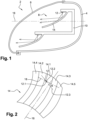
- FIG. 1 illustrates a headlight for a motor vehicle, in accordance with the invention, comprising a light module also in accordance with the invention, according to any one of the embodiments.
- FIG. 1 illustrates a motor vehicle headlight 2, essentially comprising a housing 4 forming an opening covered by a glass 6.
- the housing 4 of the headlight 2 contains a light module 8 capable of forming a light beam with horizontal cut-off and optionally with an oblique part, corresponding to a lighting beam commonly referred to as "code” or "low-beam” in English.
- the light module 8 essentially comprises a support 10, a light source 12 and a reflecting surface 14.
- the latter is advantageously of the parabolic type, that is to say, generally speaking, a surface having a single focus, that is to say a zone of convergence of the light rays such that the light rays emitted by the light source placed at the level of this zone of convergence are projected at a great distance after reflection on the surface. Projected at a great distance means that these light rays do not converge towards an area located at least 10 times the dimensions of the reflector. In other words, the reflected rays do not converge to a convergence zone or, if they converge, this convergence zone is located at a distance greater than or equal to 10 times the dimensions of the reflector.
- a parabolic surface may or may not have parabolic portions.
- a reflector with such a surface is generally used alone to create a light beam.
- the reflective surface 14 is configured to reflect the light rays emitted by the light source 12, along the optical axis 16.
- the projector may comprise another light module, in this case located under the light module 8, in particular configured to form, with the light module 8, an uninterrupted light beam, commonly referred to as “road” or “high-beam” in English.
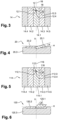
- FIG. 2 illustrates in perspective the reflective surface and the light source of the light module of the projector of the figure 1 . It applies to all embodiments, it being understood that for the sixth embodiment the angle ⁇ mentioned in the description of this figure is equal to 0.
- FIG 2 illustrates in perspective the light source 12 and the reflective surface 14 of the light module of the figure 1 .
- the reflecting surface 14 is subdivided into several zones 14.1-14.5 extending essentially longitudinally, that is to say along the optical axis 16, and arranged side by side laterally.
- these different zones are configured to form, from the same light source 12, different light images which, superimposed, will form the light beam.
- these zones although advantageously generally parabolic, have specific surfaces in that they are deformed relative to portions of the parabolic surface of revolution, depending on the light image that they must form.
- the light source 12 is a semiconductor and has a generally flat illuminating surface provided with a front edge 12.1 and a rear edge 12.2.
- the front edge 12.1 is advantageously rectilinear and is capable of forming with the reflecting surface 14 the horizontal cutoff of the light beam.
- the illuminating surface is advantageously generally rectangular and has a main axis 12.3 parallel to the front and rear edges 12.1 and 12.2. It can be observed that the source light source 12 is inclined so that its main axis 12.3 forms an angle ⁇ with a direction 18 perpendicular to the optical axis 16. This direction 18 and the main axis 12.3 of the light source 12 are advantageously in a horizontal plane when the light module is in the mounting position, as illustrated in FIG. figure 1 .
- the angle ⁇ can be greater than or equal to 10° and/or less than or equal to 45°. In this case it is of the order of 15°.
- the angle ⁇ represented in the figure 2 (also at the figure 3 ) is exaggerated for the sake of clarity of exposition.
- FIGS. 3 and 4 illustrate somewhat schematically the functions of the different zones 14.1-14.5 of the reflecting surface 14.
- the hatching on these zones at the figure 3 and the hatching on the light images at the figure 4 correspond, that is, the area(s) covered by one type of hatching form a light image represented by the same type of hatching.
- the central zone 14.1 is intersected by the optical axis 16 as well as by the emission axis 12.4 of the light source 12, this axis being perpendicular to the plane of the illuminating surface of said source.
- This zone is configured to form the light image 20.1 with oblique cutoff at the figure 4 .
- the angle ⁇ of inclination of the light source 12 corresponds to the angle of inclination of the oblique cut-off.
- the front emission edge 12.1 of the light source 12 then forms the oblique cut-off.
- the central zone 14.1 is then a surface portion, advantageously of the parabolic type, somewhat deformed to form an image that is more concentrated vertically and horizontally and also laterally offset.
- Such adaptations of surface portions can be carried out by those skilled in the art, in particular by commercially available digital means, provided that the operating conditions as described above are known.
- the lateral zones 14.2 and 14.3, adjacent to the central zone 14.1, and on either side of the optical axis 16, are configured to form the luminous image 20.2 with horizontal cut-off.
- This is a vertically concentrated image, extended horizontally and having a horizontal cut-off edge located just below the horizontal axis H.
- These adjacent lateral zones 14.2 and 14.3 are then deformed, in particular with respect to a parabolic surface of revolution, in particular so as to vertically concentrate the reflected light rays. They must also correct the inclination ⁇ of the front emission edge 12.1 in order to form an image of said horizontal edge, corresponding to the cut-off edge of the light beam 20.
- the extra-lateral zones 14.4 and 14.5, adjacent to the adjacent lateral zones 14.2 and 14.3, are configured to form a diffuse image 20.3, located below the horizontal axis H.
- This arrangement of the functional areas of the reflective surface thus makes it possible to use more surface area to form the horizontal cut-off and thus to make this image brighter.
- the inclination of the light source also makes it possible to achieve a sharper oblique cut-off.
- FIGS. 5 and 6 illustrate a second embodiment of the invention.
- the reference numbers of the first embodiment are used to designate identical or corresponding elements, these numbers being increased by 100. Reference is also made to the description of these elements in the context of the first embodiment.
- the configuration of the reflective surface 114 at the figure 5 is similar to that at the figure 3 of the first embodiment.
- the reflective surface 114 is however distinguished from the reflective surface 14 ( figure 3 ) in that the central zone 114.1 is configured to form a light image 120.1 with an oblique cut-off of a different shape, namely in the form of a parallelogram inclined at an angle ⁇ potentially different from the angle ⁇ of inclination of the light source 112.
- the overall light image 120 thus formed thus has a Z cut-off unlike the light image 20 ( figure 4 ) of the first embodiment which has a V-shaped cut.
- FIGS. 7 and 8 illustrate a third embodiment of the invention.
- the reference numbers of the first embodiment are used to designate identical or corresponding elements, these numbers being however increased by 200. Reference is also made to the description of these elements in the context of the first embodiment.
- the reflective surface 214 is distinguished from the reflective surface 14 of the first embodiment ( figure 3 ) essentially in that the central zone 214.1 is inclined by an angle ⁇ relative to the optical axis 216, greater than or equal to 5° and/or less than or equal to 20°, advantageously greater than or equal to 10°.
- the boundaries between the adjacent lateral zones 214.2 and 214.3 and the central zone 214.1 are thus inclined by the angle ⁇ .
- the overall light image 220 produced is similar to that of the figure 4 relating to the first embodiment.
- the configuration of the Figures 7 and 8 may be advantageous in that it homogenizes oblique cut-off and horizontal cut-off light images by collecting light differentially laterally and longitudinally.
- This configuration is advantageous in the case of a reflector material, such as thermosetting plastic, requiring the application of a varnish before the reflective treatment.
- FIGS. 9 and 10 illustrate a fourth embodiment of the invention.
- the reference numbers of the first embodiment are used to designate identical or corresponding elements, these numbers being however increased by 300. Reference is also made to the description of these elements in the context of the first embodiment.
- the reflective surface 314 is distinguished from the reflective surface 14 of the first embodiment ( figure 3 ) essentially in that the central zone 314.1 is configured to form the diffuse light image 320.3, one of the adjacent lateral zones 314.2 and 314.3, in this case the zone 314.2 is configured to form the horizontal cut-off light image 320.2 and the other 314.3 of said adjacent lateral zones is configured to form the oblique cut-off light image 320.1. Extra-lateral zones with functions distinct from the others are then not present. In this configuration, the central zones 314.1 and adjacent lateral zones 314.2 and 314.3 may be wider than in the previous embodiments.
- the oblique cut-off light image 320.1 has the general shape of a parallelogram so as to form with the horizontal cut-off light image 320.2 a horizontal cut-off in Z.
- the angle of inclination ⁇ of the cut-off is advantageously greater than the angle of inclination ⁇ of the light source 312.
- FIGS. 11 and 12 illustrate a fifth embodiment of the invention.
- the reference numbers of the first embodiment are used to designate identical or corresponding elements, these numbers being however increased by 400. Reference is also made to the description of these elements in the context of the first embodiment.
- the reflective surface 414 is distinguished from the reflective surface 14 of the first embodiment ( figure 3 ) essentially in that the adjacent lateral areas and the extra-lateral areas are reversed. More specifically, the lateral areas 414.2 and 414.3, adjacent to the central area 414.1, are configured to form the diffuse light image 420.3, while the extra-lateral areas 414.4 and 414.5, adjacent to the lateral areas 414.2 and 414.3 adjacent to the central area 414.1, are configured to form the horizontal cut-off light image 420.2.
- the oblique cut-off light image 420.1 has the general shape of a parallelogram so as to form a horizontal Z cut-off with the horizontal cut-off light image 420.2.
- the angle of inclination ⁇ of the cut-off corresponds to the angle of inclination ⁇ of the light source 412.
- FIGS. 13 and 14 illustrate a sixth embodiment of the invention.
- the reference numbers of the first embodiment are used to designate identical or corresponding elements, these numbers being increased by 500. Reference is also made to the description of these elements in the context of the first embodiment.
- the reflective surface 514 is distinguished from the reflective surface 14 of the first embodiment ( figure 3 ) essentially in that it does not comprise an area configured to form an oblique cut-off light image. More specifically, the reflective surface 514 comprises a central area 514.1 and two adjacent lateral areas 514.2 and 514.3 configured to form a horizontal cut-off light image 520.2, and two extra-lateral areas, adjacent to the two lateral areas 514.2 and 514.3 adjacent to the central area 514.1, configured to form a diffuse light image 520.3. Since no oblique cut-off is present, the light source 520 advantageously is not inclined.
- the overall light image 520 has a horizontal cut, without an oblique cut.
- the different configurations described above illustrate the advantages of flexibility in producing the cut-off light beam, in particular depending on the type of light source and the space available for the reflecting surface.
- the reflecting surface can thus be configured in different ways, in particular with a view to optimizing its complexity, the connections between the different zones, and also with a view to forming a specific light image, such as in particular with a horizontal Z cut-off.
- the different configurations described above are not exhaustive, other configurations being conceivable.
Landscapes
- Engineering & Computer Science (AREA)
- General Engineering & Computer Science (AREA)
- Physics & Mathematics (AREA)
- Microelectronics & Electronic Packaging (AREA)
- Optics & Photonics (AREA)
- Non-Portable Lighting Devices Or Systems Thereof (AREA)
Claims (14)
- Leuchtmodul (8) für ein Kraftfahrzeug, umfassend:- eine Halbleiter-Lichtquelle (12; 112; 212; 312; 412; 512) mit einer im Allgemeinen planen beleuchtenden Fläche, die geeignet ist, Licht entlang einer senkrecht zu der Ebene verlaufenden Emissionsachse (12.4; 112.4; 212.4; 312.4; 412.4; 512.4) zu emittieren;- eine Reflexionsfläche (14; 114; 214; 314; 414; 514), die geeignet ist, mindestens einen Teil des von der Lichtquelle (12; 112; 212; 312; 412; 512) emittierten Lichts zu reflektieren, so dass, entlang einer optischen Achse (16; 116; 216; 316; 416; 516), ein Lichtbündel mit Hell-Dunkel-Grenze (20; 120; 220; 320; 420; 520) gebildet wird, und umfassend:∘ einen zentralen Bereich (14.1; 114.1; 214.1; 314.1; 414.1; 514.1), der von der optischen Achse (16; 116; 216; 316; 416; 516) und der Emissionsachse (12.4; 112.4; 212.4; 312.4; 412.4; 512.4) geschnitten wird; und∘ mindestens einen Bereich (14.2-14.5; 114.2-114.5; 214.2-214.5; 314.2, 314.3; 414.2-414.5; 514.2-515.5) seitlich zu dem zentralen Bereich (14.1; 114.1; 214.1; 314.1; 414.1; 514.1);wobei die Bereiche (14.1-14.5; 114.1-114.5; 214.1-214.5; 314.1-314.5; 414.1-414.5; 514.1-515.5) dazu ausgestaltet sind, spezifische Lichtbilder (20.1-20.3; 120.1-120.3; 220.1-220.3; 320.1-320.3; 420.1-420.3; 520.2-520.3) zu bilden, die das Lichtbündel mit Hell-Dunkel-Grenze (20; 120; 220; 320; 420; 520) bilden;dadurch gekennzeichnet, dassder oder mindestens einer (14.2, 14.3; 114.2, 114.3; 214.2, 214.3; 314.2; 414.4, 414.5; 514.2, 515.3) der seitlichen Bereiche dazu ausgestaltet ist, ein Lichtbild mit horizontaler Hell-Dunkel-Grenze (20.2; 120.2; 220.2; 320.2; 420.2; 520.2) zu bilden,und dadurch, dass die Lichtquelle (12; 112; 212; 312; 412), in der Ebene der Emissionsfläche, einen Emissionsrand (12.1; 112.1; 212.1; 312.1; 412.1) umfasst und geneigt ist, so dass der Emissionsrand einen Winkel α mit einer Senkrechten (18; 118; 218; 318; 418) zu der optischen Achse und zu der Emissionsachse bildet,und dadurch, dass der Winkel α größer oder gleich 10° und kleiner oder gleich 45° ist.
- Modul (8) nach Anspruch 1, dadurch gekennzeichnet, dass der zentrale Bereich (14.1; 114.1; 214.1; 414.1) dazu ausgestaltet ist, ein Lichtbild mit geneigter Hell-Dunkel-Grenze (20.1; 120.1; 220.1; 420.1) zu bilden.
- Modul (8) nach einem der Ansprüche 1 und 2, dadurch gekennzeichnet, dass der oder die seitlichen Bereiche (14.2, 14.3; 114.2, 114.3; 214.2, 214.3; 314.2; 514.2, 515.3), die dazu ausgestaltet sind, das Lichtbild mit horizontaler Hell-Dunkel-Grenze (20.2; 120.2; 220.2; 320.2; 520.2) zu bilden, an den zentralen Bereich (14.1; 114.1; 214.1; 314.1; 514.1) und auf einer Seite beziehungsweise zu beiden Seiten in Bezug auf die optische Achse (16; 116; 216; 516) des Bereichs angrenzt/angrenzen.
- Modul (8) nach Anspruch 1, dadurch gekennzeichnet, dass der zentrale Bereich (314.1) dazu ausgestaltet ist, ein Diffusions-Lichtbild (320.3) unter der Horizontalen zu bilden, das ausgedehnter als die anderen Lichtbilder (320.1, 320.2) ist.
- Modul (8) nach Anspruch 4, dadurch gekennzeichnet, dass der seitliche Bereich (314.2), der dazu ausgestaltet ist, das Lichtbild mit horizontaler Hell-Dunkel-Grenze (320.2) zu bilden, ein erster seitlicher Bereich ist, der an den zentralen Bereich (314.1) angrenzt, wobei die seitlichen Bereiche einen zweiten seitlichen Bereich 314.3) umfassen, der an den zentralen Bereich (314.1) angrenzt, entgegengesetzt zu dem ersten angrenzenden seitlichen Bereich (314.2) in Bezug auf die optische Achse (316), wobei der zweite angrenzende seitliche Bereich (314.3) dazu ausgestaltet ist, ein Lichtbild mit geneigter Hell-Dunkel-Grenze (320.1) zu bilden.
- Modul (8) nach einem der Ansprüche 2 und 5, dadurch gekennzeichnet, dass das Lichtbild mit geneigter Hell-Dunkel-Grenze (20.1; 220.1; 420.1) eine Neigung in Bezug auf eine horizontale Richtung aufweist, die dem Winkel α entspricht.
- Modul (8) nach einem der Ansprüche 2 und 5, dadurch gekennzeichnet, dass das Lichtbild mit geneigter Hell-Dunkel-Grenze (120.1; 320.1) eine Neigung β in Bezug auf eine horizontale Richtung aufweist, die von dem Winkel α verschieden ist.
- Modul (8) nach einem der Ansprüche 1 bis 7, dadurch gekennzeichnet, dass die seitlichen Bereiche (14.2-14.5; 114.2-114.5; 214.2-214.5; 414.2-414.5; 514.2-515.5) ferner mindestens einen extra-seitlichen Bereich (14.4, 14.5; 114.4, 114.5; 214.4, 214.5; 414.4, 414.5; 514.4, 515.5) umfassen, der an den oder einen der seitlichen Bereiche (14.2, 14.3; 114.2, 114.3; 214.2, 214.3; 414.2, 414.3; 514.2, 515.3) angrenzt, die an den zentralen Bereich (14.1; 114.1; 214.1; 414.1; 514.1) angrenzen.
- Modul (8) nach Anspruch 8, dadurch gekennzeichnet, dass der mindestens eine extra-seitliche Bereich (14.4, 14.5; 114.4, 114.5; 214.4, 214.5; 514.4, 515.5) dazu ausgestaltet ist, ein Diffusions-Lichtbild (20.3; 120.3; 220.3; 520.3) unter der Horizontalen zu bilden, das ausgedehnter als die andere Lichtbilder (20.1, 20.2; 120.1, 120.2; 220.1, 220.2; 520.1, 520.2) ist.
- Modul (8) nach Anspruch 8, dadurch gekennzeichnet, dass der mindestens eine extra-seitliche Bereich (414.4, 414.5) den seitlichen Bereichen entspricht, die dazu ausgestaltet sind, das Lichtbild mit horizontaler Hell-Dunkel-Grenze (420.2) zu bilden.
- Modul (8) nach einem der Ansprüche 1 bis 10, dadurch gekennzeichnet, dass der zentrale Bereich (214.1) Längsränder aufweist, die an die seitlichen Bereiche (214.2, 214.3) angrenzen, wobei die Ränder um einen Winkel γ in Bezug auf die optische Achse (216) geneigt sind.
- Modul (8) nach Anspruch 11, dadurch gekennzeichnet, dass der Winkel γ größer oder gleich 10° und/oder kleiner oder gleich 20° ist.
- Modul (8) nach einem der Ansprüche 1 bis 12, dadurch gekennzeichnet, dass die reflektierende Fläche (14; 114, 214; 314; 414; 514) vom parabolischen Typ ist.
- Scheinwerfer (2) umfassend ein Gehäuse (4), das eine Öffnung bildet, eine Scheibe (6) zum Verschließen der Öffnung und mindestens ein Leuchtmodul (8), dadurch gekennzeichnet, dass das mindestens eine Leuchtmodul (8) einem der Ansprüche 1 bis 13 entspricht.
Applications Claiming Priority (1)
| Application Number | Priority Date | Filing Date | Title |
|---|---|---|---|
| FR1854736A FR3081970B1 (fr) | 2018-05-31 | 2018-05-31 | Module lumineux a coupure avec reflecteur a zones |
Publications (2)
| Publication Number | Publication Date |
|---|---|
| EP3575675A1 EP3575675A1 (de) | 2019-12-04 |
| EP3575675B1 true EP3575675B1 (de) | 2024-10-09 |
Family
ID=63684004
Family Applications (1)
| Application Number | Title | Priority Date | Filing Date |
|---|---|---|---|
| EP19176612.0A Active EP3575675B1 (de) | 2018-05-31 | 2019-05-24 | Beleuchtungsmodul zur erzeugung einer hell-dunkel-grenze mit einem "zwei zonen" reflektor |
Country Status (6)
| Country | Link |
|---|---|
| EP (1) | EP3575675B1 (de) |
| JP (1) | JP7551281B2 (de) |
| CN (1) | CN110553221B (de) |
| ES (1) | ES3008461T3 (de) |
| FR (1) | FR3081970B1 (de) |
| HU (1) | HUE069717T2 (de) |
Families Citing this family (1)
| Publication number | Priority date | Publication date | Assignee | Title |
|---|---|---|---|---|
| JP7505186B2 (ja) * | 2020-01-17 | 2024-06-25 | 市光工業株式会社 | 車両用灯具 |
Family Cites Families (12)
| Publication number | Priority date | Publication date | Assignee | Title |
|---|---|---|---|---|
| CN100483013C (zh) * | 2004-01-09 | 2009-04-29 | 株式会社小糸制作所 | 车用前照灯 |
| JP2008171743A (ja) * | 2007-01-15 | 2008-07-24 | Koito Mfg Co Ltd | 車両用前照灯 |
| JP2009277482A (ja) * | 2008-05-14 | 2009-11-26 | Ichikoh Ind Ltd | 車両用灯具 |
| JP5460225B2 (ja) * | 2009-10-09 | 2014-04-02 | 株式会社小糸製作所 | 車両用前照灯装置 |
| JP2011171121A (ja) * | 2010-02-18 | 2011-09-01 | Ichikoh Ind Ltd | 車両用前照灯 |
| JP5526453B2 (ja) * | 2010-09-13 | 2014-06-18 | スタンレー電気株式会社 | 車両用前照灯 |
| JP5698065B2 (ja) * | 2011-04-22 | 2015-04-08 | 株式会社小糸製作所 | 障害物検出装置 |
| JP5722691B2 (ja) * | 2011-04-22 | 2015-05-27 | 株式会社小糸製作所 | 車両用前照灯 |
| JP6042741B2 (ja) * | 2013-02-14 | 2016-12-14 | スタンレー電気株式会社 | 車両用灯具 |
| JP6474122B2 (ja) * | 2014-09-16 | 2019-02-27 | 株式会社小糸製作所 | 車両用灯具 |
| US10054277B2 (en) * | 2014-09-16 | 2018-08-21 | Koito Manufacturing Co., Ltd. | Vehicle lamp |
| FR3047541B1 (fr) * | 2015-12-10 | 2019-10-04 | Valeo Vision | Module d'eclairage automobile avec fonctions code et route combinees et une source lumineuse ajustable |
-
2018
- 2018-05-31 FR FR1854736A patent/FR3081970B1/fr active Active
-
2019
- 2019-05-24 HU HUE19176612A patent/HUE069717T2/hu unknown
- 2019-05-24 ES ES19176612T patent/ES3008461T3/es active Active
- 2019-05-24 EP EP19176612.0A patent/EP3575675B1/de active Active
- 2019-05-28 CN CN201910454524.0A patent/CN110553221B/zh active Active
- 2019-05-30 JP JP2019101226A patent/JP7551281B2/ja active Active
Also Published As
| Publication number | Publication date |
|---|---|
| FR3081970A1 (fr) | 2019-12-06 |
| ES3008461T3 (en) | 2025-03-24 |
| JP2019212625A (ja) | 2019-12-12 |
| JP7551281B2 (ja) | 2024-09-17 |
| HUE069717T2 (hu) | 2025-04-28 |
| EP3575675A1 (de) | 2019-12-04 |
| CN110553221A (zh) | 2019-12-10 |
| FR3081970B1 (fr) | 2021-06-11 |
| CN110553221B (zh) | 2023-06-06 |
Similar Documents
| Publication | Publication Date | Title |
|---|---|---|
| EP3708904B1 (de) | Leuchtvorrichtung, die die beleuchteten flächen von mindestens zwei kollektoren abbildet | |
| EP2422130B1 (de) | Fahrzeugscheinwerfer mit einer verbesserten fernlicht | |
| EP3167226B1 (de) | Beleuchtungsmodul für ein kraftfahrzeug | |
| EP2607165B1 (de) | Beleuchtungsmodul mit zumindest zwei im wesentlich senkrecht zueinander angeordneten Lichtquellen | |
| EP3708905B1 (de) | Beleuchtungsvorrichtung zur abbildung eines gespiegelten bilds eines kollektors | |
| EP3521692B1 (de) | Bifunktions-leuchtmodul mit gemeinsamer beleuchteter fläche | |
| EP4264122A1 (de) | Kraftfahrzeugbeleuchtungsmodul | |
| EP4264120A1 (de) | Kraftfahrzeugscheinwerfer mit mehreren beleuchtungsmodulen auf einer geneigten gemeinsamen platte | |
| EP4062098A1 (de) | Kombiniertes leuchtmodul zur abbildung der beleuchteten fläche eines kollektors | |
| FR3130011A1 (fr) | Dispositif lumineux d’un véhicule automobile | |
| EP3575675B1 (de) | Beleuchtungsmodul zur erzeugung einer hell-dunkel-grenze mit einem "zwei zonen" reflektor | |
| EP4264123B1 (de) | Beleuchtungsvorrichtung mit doppelfunktion und rotierender linse | |
| WO2022269006A1 (fr) | Dispositif lumineux pour vehicule automobile avec une lentille de projection commune pour deux ensembles optiques | |
| EP1790906B1 (de) | Beleuchtungs- oder Signaleinrichtung für Kraftfahrzeuge | |
| WO2025056743A1 (fr) | Dispositif d'eclairage pour vehicule automobile modulable entre conduite a gauche et conduite a droite et avec fonction virage | |
| WO2024033122A1 (fr) | Projecteur á coupure et étendu verticalement pour véhicule automobile | |
| EP3722663A1 (de) | Optische einheit, die einen lichtstrahl mit hell-dunkel-grenze erzeugen kann | |
| WO2024061970A1 (fr) | Module lumineux | |
| WO2025021617A1 (fr) | Module lumineux d'un véhicule automobile | |
| WO2024133404A1 (fr) | Dispositif lumineux comprenant une pluralité de modules | |
| FR3054295A1 (fr) | Systeme lumineux pour dispositif d'eclairage et/ou de signalisation d'un vehicule automobile |
Legal Events
| Date | Code | Title | Description |
|---|---|---|---|
| PUAI | Public reference made under article 153(3) epc to a published international application that has entered the european phase |
Free format text: ORIGINAL CODE: 0009012 |
|
| STAA | Information on the status of an ep patent application or granted ep patent |
Free format text: STATUS: THE APPLICATION HAS BEEN PUBLISHED |
|
| AK | Designated contracting states |
Kind code of ref document: A1 Designated state(s): AL AT BE BG CH CY CZ DE DK EE ES FI FR GB GR HR HU IE IS IT LI LT LU LV MC MK MT NL NO PL PT RO RS SE SI SK SM TR |
|
| AX | Request for extension of the european patent |
Extension state: BA ME |
|
| STAA | Information on the status of an ep patent application or granted ep patent |
Free format text: STATUS: REQUEST FOR EXAMINATION WAS MADE |
|
| 17P | Request for examination filed |
Effective date: 20200525 |
|
| RBV | Designated contracting states (corrected) |
Designated state(s): AL AT BE BG CH CY CZ DE DK EE ES FI FR GB GR HR HU IE IS IT LI LT LU LV MC MK MT NL NO PL PT RO RS SE SI SK SM TR |
|
| STAA | Information on the status of an ep patent application or granted ep patent |
Free format text: STATUS: EXAMINATION IS IN PROGRESS |
|
| 17Q | First examination report despatched |
Effective date: 20220124 |
|
| P01 | Opt-out of the competence of the unified patent court (upc) registered |
Effective date: 20230528 |
|
| RIC1 | Information provided on ipc code assigned before grant |
Ipc: F21S 41/147 20180101ALI20231019BHEP Ipc: F21S 41/33 20180101ALI20231019BHEP Ipc: F21S 41/148 20180101ALI20231019BHEP Ipc: F21S 41/155 20180101AFI20231019BHEP |
|
| GRAP | Despatch of communication of intention to grant a patent |
Free format text: ORIGINAL CODE: EPIDOSNIGR1 |
|
| STAA | Information on the status of an ep patent application or granted ep patent |
Free format text: STATUS: GRANT OF PATENT IS INTENDED |
|
| INTG | Intention to grant announced |
Effective date: 20231124 |
|
| GRAJ | Information related to disapproval of communication of intention to grant by the applicant or resumption of examination proceedings by the epo deleted |
Free format text: ORIGINAL CODE: EPIDOSDIGR1 |
|
| STAA | Information on the status of an ep patent application or granted ep patent |
Free format text: STATUS: EXAMINATION IS IN PROGRESS |
|
| INTC | Intention to grant announced (deleted) | ||
| GRAP | Despatch of communication of intention to grant a patent |
Free format text: ORIGINAL CODE: EPIDOSNIGR1 |
|
| STAA | Information on the status of an ep patent application or granted ep patent |
Free format text: STATUS: GRANT OF PATENT IS INTENDED |
|
| INTG | Intention to grant announced |
Effective date: 20240429 |
|
| GRAS | Grant fee paid |
Free format text: ORIGINAL CODE: EPIDOSNIGR3 |
|
| GRAA | (expected) grant |
Free format text: ORIGINAL CODE: 0009210 |
|
| STAA | Information on the status of an ep patent application or granted ep patent |
Free format text: STATUS: THE PATENT HAS BEEN GRANTED |
|
| REG | Reference to a national code |
Ref country code: DE Ref legal event code: R081 Ref document number: 602019059942 Country of ref document: DE Owner name: VALEO VISION, FR Free format text: FORMER OWNER: VALEO VISION, BOBIGNY, FR |
|
| AK | Designated contracting states |
Kind code of ref document: B1 Designated state(s): AL AT BE BG CH CY CZ DE DK EE ES FI FR GB GR HR HU IE IS IT LI LT LU LV MC MK MT NL NO PL PT RO RS SE SI SK SM TR |
|
| REG | Reference to a national code |
Ref country code: CH Ref legal event code: EP |
|
| REG | Reference to a national code |
Ref country code: DE Ref legal event code: R096 Ref document number: 602019059942 Country of ref document: DE |
|
| REG | Reference to a national code |
Ref country code: IE Ref legal event code: FG4D Free format text: LANGUAGE OF EP DOCUMENT: FRENCH |
|
| REG | Reference to a national code |
Ref country code: LT Ref legal event code: MG9D |
|
| REG | Reference to a national code |
Ref country code: SE Ref legal event code: TRGR |
|
| REG | Reference to a national code |
Ref country code: NL Ref legal event code: MP Effective date: 20241009 |
|
| REG | Reference to a national code |
Ref country code: AT Ref legal event code: MK05 Ref document number: 1730941 Country of ref document: AT Kind code of ref document: T Effective date: 20241009 |
|
| PG25 | Lapsed in a contracting state [announced via postgrant information from national office to epo] |
Ref country code: NL Free format text: LAPSE BECAUSE OF FAILURE TO SUBMIT A TRANSLATION OF THE DESCRIPTION OR TO PAY THE FEE WITHIN THE PRESCRIBED TIME-LIMIT Effective date: 20241009 |
|
| REG | Reference to a national code |
Ref country code: ES Ref legal event code: FG2A Ref document number: 3008461 Country of ref document: ES Kind code of ref document: T3 Effective date: 20250324 |
|
| PG25 | Lapsed in a contracting state [announced via postgrant information from national office to epo] |
Ref country code: NL Free format text: LAPSE BECAUSE OF FAILURE TO SUBMIT A TRANSLATION OF THE DESCRIPTION OR TO PAY THE FEE WITHIN THE PRESCRIBED TIME-LIMIT Effective date: 20241009 |
|
| PG25 | Lapsed in a contracting state [announced via postgrant information from national office to epo] |
Ref country code: PT Free format text: LAPSE BECAUSE OF FAILURE TO SUBMIT A TRANSLATION OF THE DESCRIPTION OR TO PAY THE FEE WITHIN THE PRESCRIBED TIME-LIMIT Effective date: 20250210 Ref country code: HR Free format text: LAPSE BECAUSE OF FAILURE TO SUBMIT A TRANSLATION OF THE DESCRIPTION OR TO PAY THE FEE WITHIN THE PRESCRIBED TIME-LIMIT Effective date: 20241009 Ref country code: IS Free format text: LAPSE BECAUSE OF FAILURE TO SUBMIT A TRANSLATION OF THE DESCRIPTION OR TO PAY THE FEE WITHIN THE PRESCRIBED TIME-LIMIT Effective date: 20250209 |
|
| PG25 | Lapsed in a contracting state [announced via postgrant information from national office to epo] |
Ref country code: FI Free format text: LAPSE BECAUSE OF FAILURE TO SUBMIT A TRANSLATION OF THE DESCRIPTION OR TO PAY THE FEE WITHIN THE PRESCRIBED TIME-LIMIT Effective date: 20241009 |
|
| PG25 | Lapsed in a contracting state [announced via postgrant information from national office to epo] |
Ref country code: BG Free format text: LAPSE BECAUSE OF FAILURE TO SUBMIT A TRANSLATION OF THE DESCRIPTION OR TO PAY THE FEE WITHIN THE PRESCRIBED TIME-LIMIT Effective date: 20241009 |
|
| PG25 | Lapsed in a contracting state [announced via postgrant information from national office to epo] |
Ref country code: NO Free format text: LAPSE BECAUSE OF FAILURE TO SUBMIT A TRANSLATION OF THE DESCRIPTION OR TO PAY THE FEE WITHIN THE PRESCRIBED TIME-LIMIT Effective date: 20250109 |
|
| PG25 | Lapsed in a contracting state [announced via postgrant information from national office to epo] |
Ref country code: LV Free format text: LAPSE BECAUSE OF FAILURE TO SUBMIT A TRANSLATION OF THE DESCRIPTION OR TO PAY THE FEE WITHIN THE PRESCRIBED TIME-LIMIT Effective date: 20241009 Ref country code: GR Free format text: LAPSE BECAUSE OF FAILURE TO SUBMIT A TRANSLATION OF THE DESCRIPTION OR TO PAY THE FEE WITHIN THE PRESCRIBED TIME-LIMIT Effective date: 20250110 Ref country code: AT Free format text: LAPSE BECAUSE OF FAILURE TO SUBMIT A TRANSLATION OF THE DESCRIPTION OR TO PAY THE FEE WITHIN THE PRESCRIBED TIME-LIMIT Effective date: 20241009 |
|
| PG25 | Lapsed in a contracting state [announced via postgrant information from national office to epo] |
Ref country code: PL Free format text: LAPSE BECAUSE OF FAILURE TO SUBMIT A TRANSLATION OF THE DESCRIPTION OR TO PAY THE FEE WITHIN THE PRESCRIBED TIME-LIMIT Effective date: 20241009 |
|
| REG | Reference to a national code |
Ref country code: HU Ref legal event code: AG4A Ref document number: E069717 Country of ref document: HU |
|
| PG25 | Lapsed in a contracting state [announced via postgrant information from national office to epo] |
Ref country code: RS Free format text: LAPSE BECAUSE OF FAILURE TO SUBMIT A TRANSLATION OF THE DESCRIPTION OR TO PAY THE FEE WITHIN THE PRESCRIBED TIME-LIMIT Effective date: 20250109 |
|
| PG25 | Lapsed in a contracting state [announced via postgrant information from national office to epo] |
Ref country code: SM Free format text: LAPSE BECAUSE OF FAILURE TO SUBMIT A TRANSLATION OF THE DESCRIPTION OR TO PAY THE FEE WITHIN THE PRESCRIBED TIME-LIMIT Effective date: 20241009 |
|
| PGFP | Annual fee paid to national office [announced via postgrant information from national office to epo] |
Ref country code: DE Payment date: 20250513 Year of fee payment: 7 |
|
| PG25 | Lapsed in a contracting state [announced via postgrant information from national office to epo] |
Ref country code: DK Free format text: LAPSE BECAUSE OF FAILURE TO SUBMIT A TRANSLATION OF THE DESCRIPTION OR TO PAY THE FEE WITHIN THE PRESCRIBED TIME-LIMIT Effective date: 20241009 |
|
| PGFP | Annual fee paid to national office [announced via postgrant information from national office to epo] |
Ref country code: ES Payment date: 20250610 Year of fee payment: 7 Ref country code: GB Payment date: 20250521 Year of fee payment: 7 |
|
| REG | Reference to a national code |
Ref country code: DE Ref legal event code: R097 Ref document number: 602019059942 Country of ref document: DE |
|
| PGFP | Annual fee paid to national office [announced via postgrant information from national office to epo] |
Ref country code: HU Payment date: 20250430 Year of fee payment: 7 |
|
| PG25 | Lapsed in a contracting state [announced via postgrant information from national office to epo] |
Ref country code: EE Free format text: LAPSE BECAUSE OF FAILURE TO SUBMIT A TRANSLATION OF THE DESCRIPTION OR TO PAY THE FEE WITHIN THE PRESCRIBED TIME-LIMIT Effective date: 20241009 |
|
| PGFP | Annual fee paid to national office [announced via postgrant information from national office to epo] |
Ref country code: FR Payment date: 20250530 Year of fee payment: 7 |
|
| PG25 | Lapsed in a contracting state [announced via postgrant information from national office to epo] |
Ref country code: RO Free format text: LAPSE BECAUSE OF FAILURE TO SUBMIT A TRANSLATION OF THE DESCRIPTION OR TO PAY THE FEE WITHIN THE PRESCRIBED TIME-LIMIT Effective date: 20241009 |
|
| PG25 | Lapsed in a contracting state [announced via postgrant information from national office to epo] |
Ref country code: SK Free format text: LAPSE BECAUSE OF FAILURE TO SUBMIT A TRANSLATION OF THE DESCRIPTION OR TO PAY THE FEE WITHIN THE PRESCRIBED TIME-LIMIT Effective date: 20241009 |
|
| PGFP | Annual fee paid to national office [announced via postgrant information from national office to epo] |
Ref country code: TR Payment date: 20250514 Year of fee payment: 7 |
|
| PGFP | Annual fee paid to national office [announced via postgrant information from national office to epo] |
Ref country code: CZ Payment date: 20250520 Year of fee payment: 7 |
|
| PG25 | Lapsed in a contracting state [announced via postgrant information from national office to epo] |
Ref country code: IT Free format text: LAPSE BECAUSE OF FAILURE TO SUBMIT A TRANSLATION OF THE DESCRIPTION OR TO PAY THE FEE WITHIN THE PRESCRIBED TIME-LIMIT Effective date: 20241009 |
|
| PGFP | Annual fee paid to national office [announced via postgrant information from national office to epo] |
Ref country code: SE Payment date: 20250519 Year of fee payment: 7 |
|
| PLBE | No opposition filed within time limit |
Free format text: ORIGINAL CODE: 0009261 |
|
| STAA | Information on the status of an ep patent application or granted ep patent |
Free format text: STATUS: NO OPPOSITION FILED WITHIN TIME LIMIT |
|
| 26N | No opposition filed |
Effective date: 20250710 |
|
| REG | Reference to a national code |
Ref country code: CH Ref legal event code: H13 Free format text: ST27 STATUS EVENT CODE: U-0-0-H10-H13 (AS PROVIDED BY THE NATIONAL OFFICE) Effective date: 20251223 |
|
| PG25 | Lapsed in a contracting state [announced via postgrant information from national office to epo] |
Ref country code: LU Free format text: LAPSE BECAUSE OF NON-PAYMENT OF DUE FEES Effective date: 20250524 |
|
| PG25 | Lapsed in a contracting state [announced via postgrant information from national office to epo] |
Ref country code: CH Free format text: LAPSE BECAUSE OF NON-PAYMENT OF DUE FEES Effective date: 20250531 |
|
| REG | Reference to a national code |
Ref country code: BE Ref legal event code: MM Effective date: 20250531 |
|
| PG25 | Lapsed in a contracting state [announced via postgrant information from national office to epo] |
Ref country code: MC Free format text: LAPSE BECAUSE OF FAILURE TO SUBMIT A TRANSLATION OF THE DESCRIPTION OR TO PAY THE FEE WITHIN THE PRESCRIBED TIME-LIMIT Effective date: 20241009 |
|
| PG25 | Lapsed in a contracting state [announced via postgrant information from national office to epo] |
Ref country code: IE Free format text: LAPSE BECAUSE OF NON-PAYMENT OF DUE FEES Effective date: 20250524 |
|
| PG25 | Lapsed in a contracting state [announced via postgrant information from national office to epo] |
Ref country code: BE Free format text: LAPSE BECAUSE OF NON-PAYMENT OF DUE FEES Effective date: 20250531 |