EP3722115B1 - Station de gonflage des pneus et procédé de fonctionnement associé - Google Patents
Station de gonflage des pneus et procédé de fonctionnement associé Download PDFInfo
- Publication number
- EP3722115B1 EP3722115B1 EP20156072.9A EP20156072A EP3722115B1 EP 3722115 B1 EP3722115 B1 EP 3722115B1 EP 20156072 A EP20156072 A EP 20156072A EP 3722115 B1 EP3722115 B1 EP 3722115B1
- Authority
- EP
- European Patent Office
- Prior art keywords
- inflation
- tire
- filling
- station
- bell
- Prior art date
- Legal status (The legal status is an assumption and is not a legal conclusion. Google has not performed a legal analysis and makes no representation as to the accuracy of the status listed.)
- Active
Links
- 238000011017 operating method Methods 0.000 title 1
- 238000000034 method Methods 0.000 claims description 9
- 239000000945 filler Substances 0.000 description 23
- 238000005429 filling process Methods 0.000 description 14
- 238000007789 sealing Methods 0.000 description 9
- 239000011324 bead Substances 0.000 description 4
- 238000009434 installation Methods 0.000 description 2
- 238000012423 maintenance Methods 0.000 description 2
- 238000005259 measurement Methods 0.000 description 2
- 239000000725 suspension Substances 0.000 description 2
- 230000004888 barrier function Effects 0.000 description 1
- 230000015572 biosynthetic process Effects 0.000 description 1
- 230000001419 dependent effect Effects 0.000 description 1
- 238000001514 detection method Methods 0.000 description 1
- 238000011161 development Methods 0.000 description 1
- 230000018109 developmental process Effects 0.000 description 1
- 238000005516 engineering process Methods 0.000 description 1
- 238000004519 manufacturing process Methods 0.000 description 1
- 230000003287 optical effect Effects 0.000 description 1
- 230000001953 sensory effect Effects 0.000 description 1
- 238000003860 storage Methods 0.000 description 1
- 238000011144 upstream manufacturing Methods 0.000 description 1
Images


Classifications
-
- B—PERFORMING OPERATIONS; TRANSPORTING
- B60—VEHICLES IN GENERAL
- B60C—VEHICLE TYRES; TYRE INFLATION; TYRE CHANGING; CONNECTING VALVES TO INFLATABLE ELASTIC BODIES IN GENERAL; DEVICES OR ARRANGEMENTS RELATED TO TYRES
- B60C25/00—Apparatus or tools adapted for mounting, removing or inspecting tyres
- B60C25/14—Apparatus or tools for spreading or locating tyre beads
- B60C25/145—Apparatus or tools for spreading or locating tyre beads for locating provisionally the beads of tubeless tyres against the sealing surfaces of the rims, e.g. air filling bell
Definitions
- the invention relates to a tire inflation station for filling a tire arranged on a rim with a pressurized gas, in particular compressed air.
- the invention also relates to a method for operating a tire inflation station.
- motor vehicle wheels so-called complete wheels consisting of a wheel rim and a tire fitted to the wheel rim
- complete wheels consisting of a wheel rim and a tire fitted to the wheel rim
- the rim with the mounted tire is placed on a suitable base plate, which seals the wheel downwards during the filling process.
- a filling bell with a filling ring is placed on the top of the tire, which seals the tire and the rim upwards, and through which the tire sidewall is pressed down so far during the filling process that an annular gap is created between the tire bead and the rim, through which the in compressed air fed through the inflation bell can flow into the tyre.
- the compressed air that flows in presses the tire with great force against the support plate and the inflation bell.
- the inflation bell is raised, causing the tire sidewalls to move apart in the axial direction until the tire beads have assumed their respective seated position on the rim.
- the filling ring of the filling bell must have an opening whose diameter is large enough on the one hand so that the filling bell does not hit the rim but can be slipped over the rim.
- the diameter of the opening must not be so large that the inflation bell contacts the upper tire sidewall radially outside of its high point. The inflation bell would then impede the radial movement of the tire, which could result in the tire bead not springing properly into its seat.
- a filler ring a certain diameter is therefore only suitable for a limited size range of motor vehicle wheels.
- EP 1 671 820 B1 known tire filling station has a carousel rotating device with a parallel to the axis line of the wheel / tire assembly, namely vertically aligned axis of rotation, on the circumference of which several filling rings of different diameters are arranged.
- the filling rings are all in a horizontal plane.
- a disadvantage of this tire inflation station is the relatively large lateral extent of the carousel rotating device, which requires a large installation space. This also makes it difficult to erect noise barriers around the tire inflation station.
- More tire inflation stations are from the WO2009/155503 known in which different filling rings are moved out horizontally from a filling ring magazine.
- the document DE102009046195B discloses a tire inflation station with various inflation rings which are arranged on a horizontally displaceable plate and a lifting table which brings the tire to be inflated into contact with a corresponding inflation ring.
- the object of the invention is to create a compact tire inflation station of the type specified which is suitable for a large range of different tire sizes and can be produced inexpensively.
- the tire inflation station should enable high inflation accuracy and be reliable and low-maintenance. It is also the object of the invention to specify an advantageous method for operating a tire inflation station.
- the carousel rotating device is also referred to as a turret.
- the advantages achieved with the invention are, in particular, that a high degree of flexibility with regard to the filling rings that can be used is achieved by a simple rotary movement of the turret about a horizontal axis of rotation above the lifting table. This enables better handling in particular for special sizes.
- the tire inflation station is particularly compact in terms of its lateral extent, while at the same time being easily accessible for maintenance work and the like. With the additional storage of RFID data on the filling rings and their recording and consideration in the system control, a high level of operational safety can be achieved without the risk of mix-ups, while at the same time optimizing the cycle time.
- the tire inflation station 2 shown is used for the automated filling of a complete wheel 4, comprising a tire mounted on a rim, with a pressurized gas, here compressed air, within an industrial assembly line.
- a pressurized gas here compressed air
- the tire inflation station 2 comprises a frame 6 in which a filling table or lifting table 10 is arranged, which can be adjusted in height, ie in the vertical direction, for example by means of a pneumatic cylinder 8 .
- a filling table or lifting table 10 is arranged, which can be adjusted in height, ie in the vertical direction, for example by means of a pneumatic cylinder 8 .
- the respective wheel/tire combination sometimes just referred to as a tire for the sake of simplicity, lies on the horizontally aligned support surface 12 of the lifting table 10 on.
- the complete wheel 4 is transferred into the filling position on the lifting table 10 by a conveying device (not shown) in the conveying direction 14 and then transported further.
- the lifting table 10 itself can contain or have a conveyor device, for example in the form of a conveyor belt.
- the filling bell 16 comprises a filling bell lower part 18 with a filling ring 20 adapted to the size of the tire, which compresses the tire bead over the entire circumference during the lifting process.
- compressed air is introduced into the tire via an associated compressed air supply in order to fill it.
- the arrangement is sealed during the filling process on the one hand on the underside of the tire by the contact surface 12 and on the other hand on the upper side of the tire by the filling bell upper part 22 adjoining the filling bell lower part 18 with the filling ring 20.
- the lifting table 10 is moved again moves down to the starting position, whereby the annular gap in the tire closes automatically.
- a plurality of filling rings 20, here in the example six pieces, are kept ready, which are attached to a filling ring changer, or ring changer for short.
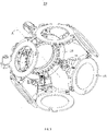
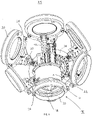
- the ring changer includes a carousel rotating device 24, also referred to as a turret, which is attached to the frame 6 of the tire inflation station 2 above the lifting table 10.
- the carousel rotating device 24 has an axis of rotation A which is perpendicular to the axis of the respective tire on the lifting table 10, namely horizontally aligned, so that the filler ring holders 26, which are arranged axisymmetricly at the same distance from the axis of rotation A, move with the filler rings 20 during a rotary movement of the carousel Rotating device 24 on a circular line (see FIG. 2 ) or move an imaginary cylinder jacket surface around the top part 22 of the filling bell, which is fixed to the frame 6 in a stationary manner.
- the axis of rotation is A of the carousel rotating device 24 also aligned parallel to the conveying direction 14 of the tires, but this is not mandatory.
- the filler rings 20 are attached to the carousel rotating device 24 by means of filler ring holders 26 in such a way that (in the side plan view of FIG. 2 ) are aligned tangentially to the circle line. In the example, this results in a substantially hexagonal outline of the turret.
- filling rings 20 can also be attached to the turret.
- the appropriate filling ring 20 can be brought into the filling position, in which it can be placed between the tire and the upper part of the filling bell with the filling ring axis aligned parallel to the tire axis 22 is arranged.
- the respective filling ring holder 26 with the filling ring 20 attached to it forms the filling bell lower part 18, which together with the filling bell upper part 22 forms the filling bell 16 as soon as both parts abut one another.
- the carousel rotating device in the example shown, a turntable 28 mounted perpendicularly to the axis of rotation A, with laterally protruding arms 30 which form or carry filler ring holders 26 .
- the entirety of the turntable 28 and filler ring holders 26 and filler rings 20 attached thereto lies within a substantially bowl-shaped outline.
- the opening area of this shell which is accessible from the outside from the side opposite the rotary disc 28, accommodates the upper part 22 of the filling bell and surrounds it in the in FIG. 1 and 2 installation position shown.
- a toothed ring can be located on the turntable 28, which is coupled to an electric drive, for example a servo drive, for setting the rotational position.
- the drive train can also be designed differently and z. B. include various gear elements. It is also conceivable to convert a linear movement caused by a linear drive into a rotary movement, for example by means of a toothed rack.
- the turret is preferably endlessly rotatable.
- the drive train can be designed to be self-locking.
- a lock can be provided which blocks the turret during the filling process.
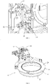
- FIG. 5 The possible solution shown comprises a pneumatic cylinder attached to the frame 6, also referred to as an index cylinder 32, on the lifting rod of which a locking element, such as a locking bolt 36, is attached for engaging in associated index bores 34 or index openings in the turntable 28. Due to the at least partially form-fitting engagement, the rotary position can be blocked as desired with a corresponding cylinder stroke of the index cylinder 32 .
- one possible variant provides a height adjustment for the upper part 22 of the filling bell, for example by means of a pneumatic cylinder or another actuator. This means that the filling bell upper part 22 is moved a certain distance vertically upwards before the rotary movement in order to create the necessary freedom of movement.
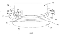
- the upper part 22 of the filling bell is moved back down into the lower end position, in which it rests on the filling ring holder 26 with the selected filling ring 20, forming the filling bell 16 (see also FIG. 7 ).
- an adjustment of the radial distance between the filler ring holder 26 and the axis of rotation A of the turret can be provided for the purpose mentioned.
- This can according to FIG. 6 be implemented, for example, by a rail guide 40 (sliding rails) and associated pneumatic cylinders or servomotors or other actuators, which are integrated into the arms 30 or suspensions carrying the filler ring holders 26, or by a corresponding adjustment mechanism in the filler ring holders 26 themselves.
- a rail guide 40 sliding rails
- associated pneumatic cylinders or servomotors or other actuators which are integrated into the arms 30 or suspensions carrying the filler ring holders 26, or by a corresponding adjustment mechanism in the filler ring holders 26 themselves.
- the adjustment integrated spring mechanism or one that is independent of it and has a corresponding spring deflection compensates for tolerances.
- the respective filler ring holder 26 preferably comprises a retaining ring or carrier ring 44 fastened laterally to an arm 30, on the underside of which the associated filler ring 20 is fastened in an exchangeable manner, for example by means of a bayonet lock.
- the width of the carrier ring 44 is greater than that of the filler ring 20 in order to accommodate filler rings 20 of different diameters.
- the carrier ring 44 accommodates, for example, a sealing ring 46 protruding upwards in an annular groove on the upper side or on the inner edge, so that the sealing plate 48 (see Fig FIG.
- the sealing plate 4 also known as the sealing plate, of the top part 22 of the filling bell during the filling process can rest against the carrier ring 44 without any gaps or leaks.
- the sealing plate 48 can be equipped with sealing means, in particular sealing rings or ring-shaped sealing zones, on its underside facing the carrier ring 44 .
- the (spherical) suspension on the outer edge of the carrier ring 44 on the arm 30 is designed in such a way that it does not impede the formation of the filling bell 16 .
- the filler rings 20 are advantageously equipped with a writable RFID chip 50 (transponder).
- This chip contains important information such as B, the diameter of the filler ring 20, the assigned rim size or the rim size range and/or other customer-specific data are stored.
- a according FIG. 7 RFID reader 52 (sensor or receiver) mounted, for example, on the top part 22 of the filling bell reads the data and feeds it to a controller for the tire inflation station 2 . In this way it can be checked and ensured that the filling ring 22 that matches the respective tire is actually in the current filling position.
- an optical or mechanically detectable coding of the filling rings 22 with corresponding sensory detection can also be provided.
- the RFID coding is generally more robust and flexible.
- All filling rings 20 can be arranged on the turret in a cycle-optimized manner.
- the arrangement of the filling rings 20 can be learned in the software of the control system by turning the turret. This means that the control moves to all locations of the turret one after the other and reads the assignment via the RFID data and saves them for use in subsequent control operations. One turret rotation after assignment is sufficient for this.
- FIG. 4 Several rod-like rim hold-down devices 56 can also be seen, which are guided through suitable recesses in the filling bell upper part 22 and which can be raised and lowered by associated actuators. When lowered, they press the rim of the complete wheel 4 lying on the lifting table 10 down. They also enable tactile measurement of the rim.
- the preferred course of the filling process can be summarized as follows: First, the complete wheel 4 to be filled is conveyed into a centering station upstream of the tire inflation station 2 .
- the complete wheel 4 is measured in the centering station, for example with regard to the outside diameter of the tire and the inside diameter of the rim.
- the measurement data are fed to the controller of the tire inflation station 2 .
- the complete wheel 4 is now conveyed into the tire inflation station 2 and placed on its lifting table 10, which is in the lowered position.
- the controller determines the appropriate filling ring 20 and the angle of rotation of the turret required for its selection. Before the rotation, the locking bolt 36 must be pulled out of the position lock of the turret by correspondingly actuating the index cylinder 32 .
- the drive for the turret is now released by the controller and rotates the selected filling ring 20 into the filling position between the complete wheel 4 and the top part 22 of the filling bell.
- the filler ring holder 26 with the filler ring 20 is now moved towards the same in the manner described above - by radial movement of the filler ring holder 26 towards the axis of rotation A of the turret and/or by lowering the upper part 22 of the filling bell, so that the complete Filling bell 26 forms.
- the controller uses the data determined by the RFID reader 52 to check that the desired filling ring 22 is actually in the filling position.
- the complete wheel 4 is now moved in the manner described above with the lifting table 10 up to the set filling ring 20 in position and filled with compressed air via the supply line connected to the upper part 22 of the filling bell.
- the lifting table 10 is moved back to the lower end position and the complete wheel 4 is conveyed out of the tire inflation station 2 .
- the filling bell upper part 22 and the filling bell lower part 18 consisting of the filling ring holder 26 and the filling ring 20 are separated again in order to create space for the next turning process.
- the process described is repeated regularly every few seconds, for example every 5 to 10 seconds.
Landscapes
- Engineering & Computer Science (AREA)
- Mechanical Engineering (AREA)
- Filling Of Jars Or Cans And Processes For Cleaning And Sealing Jars (AREA)
- Vehicle Body Suspensions (AREA)
- Superconductor Devices And Manufacturing Methods Thereof (AREA)
- External Artificial Organs (AREA)
- Moulds For Moulding Plastics Or The Like (AREA)
Claims (9)
- Station de gonflage des pneus (2) avec• une table élévatrice (10) mobile vers une partie supérieure de cloche de gonflage (22) pour un pneu à gonfler, sachant que la partie supérieure de cloche de gonflage (22) est disposée au-dessus de la table élévatrice (10), et• un système rotatif à carrousel (24) pouvant tourner autour d'un axe de rotation (A) horizontal avec une pluralité d'anneaux de gonflage (20) fixables complètement sur celui-ci, qui peuvent être déplacés dans une position de gonflage entre le pneu et la partie supérieure de cloche de gonflage (22) pour constituer une cloche de gonflage (16) par rotation correspondante du système rotatif à carrousel.
- Station de gonflage des pneus (2) selon la revendication 1, sachant que le système rotatif à carrousel (24) est disposé au-dessus de la table élévatrice (10).
- Station de gonflage des pneus (2) selon la revendication 2, sachant que le système rotatif à carrousel (24) entoure au moins en partie la partie supérieure de cloche de gonflage (22).
- Station de gonflage des pneus (2) selon l'une quelconque des revendications précédentes, sachant que la position de rotation du système rotatif à carrousel (24) peut être bloquée par un verrouillage.
- Station de gonflage des pneus (2) selon l'une quelconque des revendications précédentes, sachant que le système rotatif à carrousel (24) comporte un disque rotatif (28) avec des bras (30) ressortant latéralement, lesquels portent respectivement un support d'anneau de gonflage (26).
- Station de gonflage des pneus (2) selon la revendication 5, sachant que l'anneau de gonflage (20) respectif est fixé sur le support d'anneau de gonflage (26), pouvant être changé, de préférence au moyen d'une fermeture à baïonnette.
- Station de gonflage des pneus (2) selon la revendication 5 ou 6, sachant que dans la position de gonflage, la distance radiale entre le support d' anneau de gonflage (26) et l'axe de rotation (A) du système rotatif à carrousel (24) peut être modifiée par un actionneur.
- Station de gonflage des pneus (2) selon l'une quelconque des revendications précédentes, sachant que l'anneau de gonflage (20) respectif comporte une codification d'identification sans contact (RFID) et sachant qu'une commande associée saisit par détection la codification et la prend en considération lors de la commande de la station de gonflage des pneus (2).
- Procédé destiné à faire fonctionner une station de gonflage des pneus (2) avec une table élévatrice (10) mobile vers une partie supérieure de cloche de gonflage (22) pour un pneu à gonfler, sachant que la partie supérieure de cloche de gonflage(22) est disposée au-dessus de la table élévatrice (10) et sachant que par rotation correspondante d'un système rotatif à carrousel (24) pouvant tourner autour d'un axe de rotation (A) horizontal avec une pluralité d' anneaux de gonflage (20) fixables complètement sur celui-ci, un des anneaux de gonflage (22) est déplacé pour constituer une cloche de gonflage (16) dans une position de gonflage entre le pneu et la partie supérieure de cloche de gonflage (22).
Applications Claiming Priority (1)
| Application Number | Priority Date | Filing Date | Title |
|---|---|---|---|
| DE102019109497.6A DE102019109497A1 (de) | 2019-04-10 | 2019-04-10 | Reifenfüllstation und zugehöriges Betriebsverfahren |
Publications (2)
| Publication Number | Publication Date |
|---|---|
| EP3722115A1 EP3722115A1 (fr) | 2020-10-14 |
| EP3722115B1 true EP3722115B1 (fr) | 2022-04-06 |
Family
ID=69526185
Family Applications (1)
| Application Number | Title | Priority Date | Filing Date |
|---|---|---|---|
| EP20156072.9A Active EP3722115B1 (fr) | 2019-04-10 | 2020-02-07 | Station de gonflage des pneus et procédé de fonctionnement associé |
Country Status (4)
| Country | Link |
|---|---|
| EP (1) | EP3722115B1 (fr) |
| DE (1) | DE102019109497A1 (fr) |
| ES (1) | ES2920848T3 (fr) |
| PT (1) | PT3722115T (fr) |
Families Citing this family (1)
| Publication number | Priority date | Publication date | Assignee | Title |
|---|---|---|---|---|
| IT202100022520A1 (it) * | 2021-08-30 | 2023-03-02 | Mo S A I C Motion System And Information Control S R L | Stazione di gonfiaggio pneumatici |
Family Cites Families (5)
| Publication number | Priority date | Publication date | Assignee | Title |
|---|---|---|---|---|
| DE102004062329A1 (de) * | 2004-12-20 | 2006-06-22 | Schenck Rotec Gmbh | Reifenfüllstation und Verfahren zur Reifenfüllung |
| WO2009155503A2 (fr) * | 2008-06-20 | 2009-12-23 | Android Industries Llc | Présentoire de pile verticale permettant de présenter un anneau de gonflage |
| DE102009046195B3 (de) * | 2009-10-30 | 2011-03-17 | Schenck Rotec Gmbh | Reifenfüllstation und Verfahren zum Füllen von Reifen |
| US8770236B2 (en) * | 2009-11-20 | 2014-07-08 | Android Industries Llc | Inflator apparatus, system and method for utilizing the same |
| DE102013104007A1 (de) * | 2013-04-19 | 2014-10-23 | Schenck Rotec Gmbh | Reifenfüllvorrichtung |
-
2019
- 2019-04-10 DE DE102019109497.6A patent/DE102019109497A1/de not_active Withdrawn
-
2020
- 2020-02-07 EP EP20156072.9A patent/EP3722115B1/fr active Active
- 2020-02-07 ES ES20156072T patent/ES2920848T3/es active Active
- 2020-02-07 PT PT201560729T patent/PT3722115T/pt unknown
Also Published As
| Publication number | Publication date |
|---|---|
| PT3722115T (pt) | 2022-07-04 |
| ES2920848T3 (es) | 2022-08-10 |
| EP3722115A1 (fr) | 2020-10-14 |
| DE102019109497A1 (de) | 2020-10-15 |
Similar Documents
| Publication | Publication Date | Title |
|---|---|---|
| EP1125772B2 (fr) | Station de gonflage de pneumatiques et méthode de gonflage de pneumatiques | |
| EP2514611B1 (fr) | Dispositif et procédé de montage d'un pneu à l'aide d'un robot | |
| EP2388155B1 (fr) | Dispositif et procédé de modification de la position d'angle de rotation d'un pneu sur une jante | |
| EP2792511B1 (fr) | Dispositif de gonflage de pneumatique | |
| EP3446816B1 (fr) | Mandrin de serrage pour roues | |
| DE69828384T2 (de) | Automatische breiteneinstellbare spannfuttereinrichtung für reifenprüfmaschinen | |
| DE102009046195B3 (de) | Reifenfüllstation und Verfahren zum Füllen von Reifen | |
| DE69604799T2 (de) | Gerät und verfahren zum anbringen von reifenwülsten | |
| DE60302358T2 (de) | Reifenaufbautrommel mit umschlagvorrichtung und verfahren zur herstellung von rohreifen | |
| EP1671820B1 (fr) | Station de gonflage de pneumatiques et méthode de gonflage de pneumatiques | |
| EP1738937B1 (fr) | Procédé et dispositif d'assemblage de pneumatiques | |
| EP0349777A1 (fr) | Presse pour enrober des noyaux | |
| DE69217201T2 (de) | Verfahren und vorrichtung zum zuführen der montageteile eines reifen-wulstes | |
| EP3722115B1 (fr) | Station de gonflage des pneus et procédé de fonctionnement associé | |
| EP0792761B1 (fr) | Dispositif d'amélioration du comportement des pneumatiques automobiles par un meilleur positionnement des talons des pneus sur la jante | |
| EP3381669A1 (fr) | Procédé de typage d'un pneu de véhicule et installation de fabrication destinée à la mise en uvre dudit procédé | |
| EP1110765B1 (fr) | Système de gonflage de pneumatiques pour gonfler un pneumatique avec de l'air comprimé et méthode pour ceçi | |
| EP1362717B1 (fr) | Procédé et dispositif de montage d'un pneumatique sur une jante de roue | |
| DE3918209C2 (de) | Vorrichtung zum Beschicken einer Reifenheizpresse | |
| DE3546183C2 (de) | Vorrichtung zum fuellen schlauchloser auf felgen aufgezogener reifen | |
| EP1270279A2 (fr) | Dispositif de gonflage pour un pneumatique sans chambre à air placé sur une jante | |
| EP4086070B1 (fr) | Dispositif et procédé de fabrication de paquets de noyaux pour pneumatiques de véhicule | |
| DE69613301T2 (de) | Reifenfüllgerät | |
| EP4276437A1 (fr) | Verrouillage pour jantes | |
| DE102021118623A1 (de) | Vorrichtung und Verfahren zur gezielten Ablage einer Reifenanordnung zur Reifenfüllung in einer Reifenfüllanlage |
Legal Events
| Date | Code | Title | Description |
|---|---|---|---|
| PUAI | Public reference made under article 153(3) epc to a published international application that has entered the european phase |
Free format text: ORIGINAL CODE: 0009012 |
|
| STAA | Information on the status of an ep patent application or granted ep patent |
Free format text: STATUS: THE APPLICATION HAS BEEN PUBLISHED |
|
| AK | Designated contracting states |
Kind code of ref document: A1 Designated state(s): AL AT BE BG CH CY CZ DE DK EE ES FI FR GB GR HR HU IE IS IT LI LT LU LV MC MK MT NL NO PL PT RO RS SE SI SK SM TR |
|
| AX | Request for extension of the european patent |
Extension state: BA ME |
|
| STAA | Information on the status of an ep patent application or granted ep patent |
Free format text: STATUS: REQUEST FOR EXAMINATION WAS MADE |
|
| 17P | Request for examination filed |
Effective date: 20210121 |
|
| RBV | Designated contracting states (corrected) |
Designated state(s): AL AT BE BG CH CY CZ DE DK EE ES FI FR GB GR HR HU IE IS IT LI LT LU LV MC MK MT NL NO PL PT RO RS SE SI SK SM TR |
|
| GRAP | Despatch of communication of intention to grant a patent |
Free format text: ORIGINAL CODE: EPIDOSNIGR1 |
|
| STAA | Information on the status of an ep patent application or granted ep patent |
Free format text: STATUS: GRANT OF PATENT IS INTENDED |
|
| INTG | Intention to grant announced |
Effective date: 20210913 |
|
| GRAS | Grant fee paid |
Free format text: ORIGINAL CODE: EPIDOSNIGR3 |
|
| GRAA | (expected) grant |
Free format text: ORIGINAL CODE: 0009210 |
|
| STAA | Information on the status of an ep patent application or granted ep patent |
Free format text: STATUS: THE PATENT HAS BEEN GRANTED |
|
| AK | Designated contracting states |
Kind code of ref document: B1 Designated state(s): AL AT BE BG CH CY CZ DE DK EE ES FI FR GB GR HR HU IE IS IT LI LT LU LV MC MK MT NL NO PL PT RO RS SE SI SK SM TR |
|
| REG | Reference to a national code |
Ref country code: GB Ref legal event code: FG4D Free format text: NOT ENGLISH |
|
| REG | Reference to a national code |
Ref country code: CH Ref legal event code: EP |
|
| REG | Reference to a national code |
Ref country code: AT Ref legal event code: REF Ref document number: 1481005 Country of ref document: AT Kind code of ref document: T Effective date: 20220415 |
|
| REG | Reference to a national code |
Ref country code: DE Ref legal event code: R096 Ref document number: 502020000883 Country of ref document: DE |
|
| REG | Reference to a national code |
Ref country code: IE Ref legal event code: FG4D Free format text: LANGUAGE OF EP DOCUMENT: GERMAN |
|
| REG | Reference to a national code |
Ref country code: FI Ref legal event code: FGE |
|
| REG | Reference to a national code |
Ref country code: PT Ref legal event code: SC4A Ref document number: 3722115 Country of ref document: PT Date of ref document: 20220704 Kind code of ref document: T Free format text: AVAILABILITY OF NATIONAL TRANSLATION Effective date: 20220627 |
|
| REG | Reference to a national code |
Ref country code: NL Ref legal event code: FP |
|
| REG | Reference to a national code |
Ref country code: SE Ref legal event code: TRGR |
|
| REG | Reference to a national code |
Ref country code: LT Ref legal event code: MG9D |
|
| REG | Reference to a national code |
Ref country code: ES Ref legal event code: FG2A Ref document number: 2920848 Country of ref document: ES Kind code of ref document: T3 Effective date: 20220810 |
|
| PG25 | Lapsed in a contracting state [announced via postgrant information from national office to epo] |
Ref country code: NO Free format text: LAPSE BECAUSE OF FAILURE TO SUBMIT A TRANSLATION OF THE DESCRIPTION OR TO PAY THE FEE WITHIN THE PRESCRIBED TIME-LIMIT Effective date: 20220706 Ref country code: LT Free format text: LAPSE BECAUSE OF FAILURE TO SUBMIT A TRANSLATION OF THE DESCRIPTION OR TO PAY THE FEE WITHIN THE PRESCRIBED TIME-LIMIT Effective date: 20220406 Ref country code: HR Free format text: LAPSE BECAUSE OF FAILURE TO SUBMIT A TRANSLATION OF THE DESCRIPTION OR TO PAY THE FEE WITHIN THE PRESCRIBED TIME-LIMIT Effective date: 20220406 Ref country code: GR Free format text: LAPSE BECAUSE OF FAILURE TO SUBMIT A TRANSLATION OF THE DESCRIPTION OR TO PAY THE FEE WITHIN THE PRESCRIBED TIME-LIMIT Effective date: 20220707 Ref country code: BG Free format text: LAPSE BECAUSE OF FAILURE TO SUBMIT A TRANSLATION OF THE DESCRIPTION OR TO PAY THE FEE WITHIN THE PRESCRIBED TIME-LIMIT Effective date: 20220706 |
|
| PG25 | Lapsed in a contracting state [announced via postgrant information from national office to epo] |
Ref country code: RS Free format text: LAPSE BECAUSE OF FAILURE TO SUBMIT A TRANSLATION OF THE DESCRIPTION OR TO PAY THE FEE WITHIN THE PRESCRIBED TIME-LIMIT Effective date: 20220406 Ref country code: PL Free format text: LAPSE BECAUSE OF FAILURE TO SUBMIT A TRANSLATION OF THE DESCRIPTION OR TO PAY THE FEE WITHIN THE PRESCRIBED TIME-LIMIT Effective date: 20220406 Ref country code: LV Free format text: LAPSE BECAUSE OF FAILURE TO SUBMIT A TRANSLATION OF THE DESCRIPTION OR TO PAY THE FEE WITHIN THE PRESCRIBED TIME-LIMIT Effective date: 20220406 Ref country code: IS Free format text: LAPSE BECAUSE OF FAILURE TO SUBMIT A TRANSLATION OF THE DESCRIPTION OR TO PAY THE FEE WITHIN THE PRESCRIBED TIME-LIMIT Effective date: 20220806 |
|
| REG | Reference to a national code |
Ref country code: DE Ref legal event code: R097 Ref document number: 502020000883 Country of ref document: DE |
|
| PG25 | Lapsed in a contracting state [announced via postgrant information from national office to epo] |
Ref country code: SM Free format text: LAPSE BECAUSE OF FAILURE TO SUBMIT A TRANSLATION OF THE DESCRIPTION OR TO PAY THE FEE WITHIN THE PRESCRIBED TIME-LIMIT Effective date: 20220406 Ref country code: SK Free format text: LAPSE BECAUSE OF FAILURE TO SUBMIT A TRANSLATION OF THE DESCRIPTION OR TO PAY THE FEE WITHIN THE PRESCRIBED TIME-LIMIT Effective date: 20220406 Ref country code: RO Free format text: LAPSE BECAUSE OF FAILURE TO SUBMIT A TRANSLATION OF THE DESCRIPTION OR TO PAY THE FEE WITHIN THE PRESCRIBED TIME-LIMIT Effective date: 20220406 Ref country code: EE Free format text: LAPSE BECAUSE OF FAILURE TO SUBMIT A TRANSLATION OF THE DESCRIPTION OR TO PAY THE FEE WITHIN THE PRESCRIBED TIME-LIMIT Effective date: 20220406 Ref country code: DK Free format text: LAPSE BECAUSE OF FAILURE TO SUBMIT A TRANSLATION OF THE DESCRIPTION OR TO PAY THE FEE WITHIN THE PRESCRIBED TIME-LIMIT Effective date: 20220406 |
|
| PLBE | No opposition filed within time limit |
Free format text: ORIGINAL CODE: 0009261 |
|
| STAA | Information on the status of an ep patent application or granted ep patent |
Free format text: STATUS: NO OPPOSITION FILED WITHIN TIME LIMIT |
|
| 26N | No opposition filed |
Effective date: 20230110 |
|
| PG25 | Lapsed in a contracting state [announced via postgrant information from national office to epo] |
Ref country code: AL Free format text: LAPSE BECAUSE OF FAILURE TO SUBMIT A TRANSLATION OF THE DESCRIPTION OR TO PAY THE FEE WITHIN THE PRESCRIBED TIME-LIMIT Effective date: 20220406 |
|
| PG25 | Lapsed in a contracting state [announced via postgrant information from national office to epo] |
Ref country code: SI Free format text: LAPSE BECAUSE OF FAILURE TO SUBMIT A TRANSLATION OF THE DESCRIPTION OR TO PAY THE FEE WITHIN THE PRESCRIBED TIME-LIMIT Effective date: 20220406 |
|
| PG25 | Lapsed in a contracting state [announced via postgrant information from national office to epo] |
Ref country code: MC Free format text: LAPSE BECAUSE OF FAILURE TO SUBMIT A TRANSLATION OF THE DESCRIPTION OR TO PAY THE FEE WITHIN THE PRESCRIBED TIME-LIMIT Effective date: 20220406 |
|
| REG | Reference to a national code |
Ref country code: CH Ref legal event code: PL |
|
| PG25 | Lapsed in a contracting state [announced via postgrant information from national office to epo] |
Ref country code: LU Free format text: LAPSE BECAUSE OF NON-PAYMENT OF DUE FEES Effective date: 20230207 Ref country code: LI Free format text: LAPSE BECAUSE OF NON-PAYMENT OF DUE FEES Effective date: 20230228 Ref country code: CH Free format text: LAPSE BECAUSE OF NON-PAYMENT OF DUE FEES Effective date: 20230228 |
|
| PGFP | Annual fee paid to national office [announced via postgrant information from national office to epo] |
Ref country code: IE Payment date: 20240216 Year of fee payment: 5 Ref country code: NL Payment date: 20240220 Year of fee payment: 5 Ref country code: ES Payment date: 20240319 Year of fee payment: 5 |
|
| PGFP | Annual fee paid to national office [announced via postgrant information from national office to epo] |
Ref country code: FI Payment date: 20240219 Year of fee payment: 5 Ref country code: DE Payment date: 20240228 Year of fee payment: 5 Ref country code: CZ Payment date: 20240129 Year of fee payment: 5 Ref country code: PT Payment date: 20240130 Year of fee payment: 5 Ref country code: GB Payment date: 20240222 Year of fee payment: 5 |
|
| PGFP | Annual fee paid to national office [announced via postgrant information from national office to epo] |
Ref country code: TR Payment date: 20240131 Year of fee payment: 5 Ref country code: SE Payment date: 20240221 Year of fee payment: 5 Ref country code: IT Payment date: 20240229 Year of fee payment: 5 Ref country code: FR Payment date: 20240222 Year of fee payment: 5 Ref country code: BE Payment date: 20240219 Year of fee payment: 5 |