EP3722044B1 - Automatisches schneiden von formen aus blattmaterial - Google Patents
Automatisches schneiden von formen aus blattmaterial Download PDFInfo
- Publication number
- EP3722044B1 EP3722044B1 EP20163853.3A EP20163853A EP3722044B1 EP 3722044 B1 EP3722044 B1 EP 3722044B1 EP 20163853 A EP20163853 A EP 20163853A EP 3722044 B1 EP3722044 B1 EP 3722044B1
- Authority
- EP
- European Patent Office
- Prior art keywords
- sheet material
- cutting
- printed
- shapes
- data
- Prior art date
- Legal status (The legal status is an assumption and is not a legal conclusion. Google has not performed a legal analysis and makes no representation as to the accuracy of the status listed.)
- Active
Links
Images


Classifications
-
- B—PERFORMING OPERATIONS; TRANSPORTING
- B23—MACHINE TOOLS; METAL-WORKING NOT OTHERWISE PROVIDED FOR
- B23K—SOLDERING OR UNSOLDERING; WELDING; CLADDING OR PLATING BY SOLDERING OR WELDING; CUTTING BY APPLYING HEAT LOCALLY, e.g. FLAME CUTTING; WORKING BY LASER BEAM
- B23K26/00—Working by laser beam, e.g. welding, cutting or boring
- B23K26/36—Removing material
- B23K26/38—Removing material by boring or cutting
-
- B—PERFORMING OPERATIONS; TRANSPORTING
- B23—MACHINE TOOLS; METAL-WORKING NOT OTHERWISE PROVIDED FOR
- B23K—SOLDERING OR UNSOLDERING; WELDING; CLADDING OR PLATING BY SOLDERING OR WELDING; CUTTING BY APPLYING HEAT LOCALLY, e.g. FLAME CUTTING; WORKING BY LASER BEAM
- B23K26/00—Working by laser beam, e.g. welding, cutting or boring
- B23K26/02—Positioning or observing the workpiece, e.g. with respect to the point of impact; Aligning, aiming or focusing the laser beam
- B23K26/03—Observing, e.g. monitoring, the workpiece
- B23K26/032—Observing, e.g. monitoring, the workpiece using optical means
-
- B—PERFORMING OPERATIONS; TRANSPORTING
- B23—MACHINE TOOLS; METAL-WORKING NOT OTHERWISE PROVIDED FOR
- B23K—SOLDERING OR UNSOLDERING; WELDING; CLADDING OR PLATING BY SOLDERING OR WELDING; CUTTING BY APPLYING HEAT LOCALLY, e.g. FLAME CUTTING; WORKING BY LASER BEAM
- B23K26/00—Working by laser beam, e.g. welding, cutting or boring
- B23K26/08—Devices involving relative movement between laser beam and workpiece
- B23K26/083—Devices involving movement of the workpiece in at least one axial direction
- B23K26/0838—Devices involving movement of the workpiece in at least one axial direction by using an endless conveyor belt
- B23K26/0846—Devices involving movement of the workpiece in at least one axial direction by using an endless conveyor belt for moving elongated workpieces longitudinally, e.g. wire or strip material
-
- B—PERFORMING OPERATIONS; TRANSPORTING
- B23—MACHINE TOOLS; METAL-WORKING NOT OTHERWISE PROVIDED FOR
- B23K—SOLDERING OR UNSOLDERING; WELDING; CLADDING OR PLATING BY SOLDERING OR WELDING; CUTTING BY APPLYING HEAT LOCALLY, e.g. FLAME CUTTING; WORKING BY LASER BEAM
- B23K26/00—Working by laser beam, e.g. welding, cutting or boring
- B23K26/36—Removing material
-
- B—PERFORMING OPERATIONS; TRANSPORTING
- B26—HAND CUTTING TOOLS; CUTTING; SEVERING
- B26D—CUTTING; DETAILS COMMON TO MACHINES FOR PERFORATING, PUNCHING, CUTTING-OUT, STAMPING-OUT OR SEVERING
- B26D5/00—Arrangements for operating and controlling machines or devices for cutting, cutting-out, stamping-out, punching, perforating, or severing by means other than cutting
- B26D5/005—Computer numerical control means
-
- B—PERFORMING OPERATIONS; TRANSPORTING
- B26—HAND CUTTING TOOLS; CUTTING; SEVERING
- B26D—CUTTING; DETAILS COMMON TO MACHINES FOR PERFORATING, PUNCHING, CUTTING-OUT, STAMPING-OUT OR SEVERING
- B26D5/00—Arrangements for operating and controlling machines or devices for cutting, cutting-out, stamping-out, punching, perforating, or severing by means other than cutting
- B26D5/007—Control means comprising cameras, vision or image processing systems
-
- B—PERFORMING OPERATIONS; TRANSPORTING
- B26—HAND CUTTING TOOLS; CUTTING; SEVERING
- B26D—CUTTING; DETAILS COMMON TO MACHINES FOR PERFORATING, PUNCHING, CUTTING-OUT, STAMPING-OUT OR SEVERING
- B26D5/00—Arrangements for operating and controlling machines or devices for cutting, cutting-out, stamping-out, punching, perforating, or severing by means other than cutting
- B26D5/20—Arrangements for operating and controlling machines or devices for cutting, cutting-out, stamping-out, punching, perforating, or severing by means other than cutting with interrelated action between the cutting member and work feed
- B26D5/30—Arrangements for operating and controlling machines or devices for cutting, cutting-out, stamping-out, punching, perforating, or severing by means other than cutting with interrelated action between the cutting member and work feed having the cutting member controlled by scanning a record carrier
- B26D5/34—Arrangements for operating and controlling machines or devices for cutting, cutting-out, stamping-out, punching, perforating, or severing by means other than cutting with interrelated action between the cutting member and work feed having the cutting member controlled by scanning a record carrier scanning being effected by a photosensitive device
-
- B—PERFORMING OPERATIONS; TRANSPORTING
- B26—HAND CUTTING TOOLS; CUTTING; SEVERING
- B26F—PERFORATING; PUNCHING; CUTTING-OUT; STAMPING-OUT; SEVERING BY MEANS OTHER THAN CUTTING
- B26F1/00—Perforating; Punching; Cutting-out; Stamping-out; Apparatus therefor
- B26F1/38—Cutting-out; Stamping-out
- B26F1/3806—Cutting-out; Stamping-out wherein relative movements of tool head and work during cutting have a component tangential to the work surface
-
- B—PERFORMING OPERATIONS; TRANSPORTING
- B23—MACHINE TOOLS; METAL-WORKING NOT OTHERWISE PROVIDED FOR
- B23K—SOLDERING OR UNSOLDERING; WELDING; CLADDING OR PLATING BY SOLDERING OR WELDING; CUTTING BY APPLYING HEAT LOCALLY, e.g. FLAME CUTTING; WORKING BY LASER BEAM
- B23K2101/00—Articles made by soldering, welding or cutting
- B23K2101/18—Sheet panels
-
- B—PERFORMING OPERATIONS; TRANSPORTING
- B23—MACHINE TOOLS; METAL-WORKING NOT OTHERWISE PROVIDED FOR
- B23K—SOLDERING OR UNSOLDERING; WELDING; CLADDING OR PLATING BY SOLDERING OR WELDING; CUTTING BY APPLYING HEAT LOCALLY, e.g. FLAME CUTTING; WORKING BY LASER BEAM
- B23K2103/00—Materials to be soldered, welded or cut
- B23K2103/30—Organic materials
- B23K2103/36—Wood or similar materials
-
- B—PERFORMING OPERATIONS; TRANSPORTING
- B23—MACHINE TOOLS; METAL-WORKING NOT OTHERWISE PROVIDED FOR
- B23K—SOLDERING OR UNSOLDERING; WELDING; CLADDING OR PLATING BY SOLDERING OR WELDING; CUTTING BY APPLYING HEAT LOCALLY, e.g. FLAME CUTTING; WORKING BY LASER BEAM
- B23K2103/00—Materials to be soldered, welded or cut
- B23K2103/30—Organic materials
- B23K2103/38—Fabrics; Fibrous materials
-
- B—PERFORMING OPERATIONS; TRANSPORTING
- B23—MACHINE TOOLS; METAL-WORKING NOT OTHERWISE PROVIDED FOR
- B23K—SOLDERING OR UNSOLDERING; WELDING; CLADDING OR PLATING BY SOLDERING OR WELDING; CUTTING BY APPLYING HEAT LOCALLY, e.g. FLAME CUTTING; WORKING BY LASER BEAM
- B23K2103/00—Materials to be soldered, welded or cut
- B23K2103/30—Organic materials
- B23K2103/40—Paper
-
- B—PERFORMING OPERATIONS; TRANSPORTING
- B23—MACHINE TOOLS; METAL-WORKING NOT OTHERWISE PROVIDED FOR
- B23K—SOLDERING OR UNSOLDERING; WELDING; CLADDING OR PLATING BY SOLDERING OR WELDING; CUTTING BY APPLYING HEAT LOCALLY, e.g. FLAME CUTTING; WORKING BY LASER BEAM
- B23K2103/00—Materials to be soldered, welded or cut
- B23K2103/30—Organic materials
- B23K2103/42—Plastics other than composite materials
Definitions
- the invention relates to the automatic cutting of shapes from sheet material and provides a method of programming and operating a numerically controlled cutting machine, to cut out shapes pre-printed onto the sheet material.
- the cutting machine may be any machine which has a numerically controlled cutting head, for example a laser cutter, a hot knife cutter, a water jet cutter, a hot air jet cutter or a milling cutter, although the invention is particularly suited to laser cutters.
- the invention also includes such cutting machines when organized and programmed according to the invention.
- the pre-printed sheet material to be cut according to the invention may be flexible, such as a fabric, textile or flexible thermoplastic sheet, or may be a rigid or semi-rigid board material such as cardboard.
- Examples of flexible sheet materials that may be cut according to the invention are rolls of pre-printed textile materials suitable for use in flag, banner, clothing or footwear manufacture, real or simulated leathers, and rolls of vinyl sheet. All such flexible sheet materials are commonly cut into separate pieces for assembly into clothing, footwear, flags or banners (although that list of end uses is by no means a comprehensive list).
- the sheet material may have a plain, self-coloured or printed background, but it is a feature of the invention that cutting shape outlines and/or location marks are pre-printed on the sheet materials, and that the cutting machine follows those cutting shape outlines and/or location marks to cut through the sheet material to create the final cut shapes.
- Other features that may be printed on the sheet material may be decorative, such as pictures, or informative, such as text, or both. If the sheet material has closed loop shape outlines pre-printed thereon then the final cut pieces are pieces which are cut out closely following those closed loop shapes in outline and location. If the sheet material has location marks pre-printed thereon then any cutting command data pre-programmed into the machine is modified to align it and maintain it in close alignment with the location marks and thus with other patterns or features pre-printed on the sheet material.
- US-A-5614115 discloses one known laser cutter for cutting out shapes from sheet material.
- the sheet material is passed over a support roller onto which a collimated laser beam is focussed, and by controlling the lateral movement of a laser cutting head together with the forward and rearward movement of the sheet material, the shape outline is cut from the sheet.
- US-A-5614115 added the improvement that the shapes could be printed directly onto the sheet material and the laser cutter could be programmed to detect those pre-printed shapes and to derive cutting command data to control the cutting head to follow the pre-printed shapes, eliminating the need for border-printed location marks.
- the camera/laser cutter combination of US-A-5614115 forming the basis for the preambles of claims 1 and 7, operates in a cycle of three consecutive modes.
- a first, data capture, mode the sheet material is passed over the same support roller with the laser beam turned OFF, and a camera or other optical recognition device mounted on the same movable head that mounts the laser cutting head is used to scan the sheet material as the sheet material is moved progressively over the support roller, and to identify the shape outlines printed on the sheet material. That optical recognition device is then turned OFF and the sheet material is drawn back over the support roller to its start position, while in a second, data processing, mode the shape identification data captured is processed to create cutting command data for the laser cutter.
- cutting, mode the laser beam is turned ON and the cutting command data is used to control both the lateral movement of the laser cutting head and the forward and rearward movement of the sheet material over the support roller, to cause the laser to cut the desired outline from the sheet material.
- US-A-9868302 discloses a laser cutting machine which cuts a continuous fabric into pieces for stitching together to make clothing.
- all the data to identify the shapes to be cut is pre-programmed into the laser cutting machine together with printing command data, and as plain unprinted fabric is unrolled from a fabric roll it passes first through a printer where the fabric is printed with cutting and garment assembly data, optionally together with a decorative pattern. The fabric then passes to a laser cutting area where the shapes are cut out.
- the printing ink used for the cutting and garment assembly data is a fluorescent ink which is invisible to the human eye under normal lighting conditions, but which can be seen by the human eye or by a camera under ultraviolet light.
- UV-responsive image sensors downstream of the laser cutter monitor the process and can control the laser cutter, but the basic cutting command data is already pre-programmed into the machine for the initial printing stage, and the shapes have been cut before the fabric reaches the UV-responsive image sensors.
- WO-A-2019/012566 uses a similar combined printing and cutting machine.
- the initially plain fabric is printed with pre-programmed shapes and other potentially useful information using ink which is substantially invisible to the human eye.
- the fabric is unrolled further to pass to the cutting part of the machine where the shapes to be made up into garments are cut out.
- the shapes to be cut are pre-programmed into the machine together with the printing command data.
- UV-cameras downstream of the cutter section are responsive to the data printed on the fabric and retrieve information therefrom, and that information is used to control the cutting and potential further treatment of the fabric.
- the cameras scan the fabric only after the shapes have been cut.
- the Chinese company Golden Laser Co Ltd has developed a laser cutter for cutting out shapes from printed fabrics.
- the laser is controlled by cutting command data, and as with US-A-9868302 and WO-A-2019/012566 that cutting command data is preinstalled into the laser cutter machine to match and follow the designs printed onto the fabric.
- the laser cutter developed by Golden Laser Co Ltd is suitable for use in close proximity to a printer that is used to print the designs onto the fabric, so that the same vector data can be used both to control the print head of the printer and the laser head of the laser cutter.
- That alignment is a manual task which must be carried out before the machine cuts the fabric. It is carried out by aligning, on a computer screen, images of the printed fabric and of the cutting command data. Typically the printed fabric would have printed location marks printed thereon in addition to the printed pattern. Those marks could be at any position on the fabric: on the border, or between adjacent shapes to be cut out from the fabric by the laser cutter, or even within the cut shapes themselves.
- the image representing the cutting command data on the computer screen would include identical location marks.
- the pattern printed on the fabric may be distorted when the fabric passes to the cutting bed of the cutting machine, and to compensate for that distortion the cutting action of the laser cutter must be periodically stopped whenever the operator notices that the cut shapes no longer follow the pattern printed onto the fabric, to allow for realignment of the cutting command data and the printed patterns on the distorted fabric.
- the present invention aims to create an improved laser cutting machine which does not require periodic pauses in the cutting action to achieve the necessary alignment between the cut lines and the printed patterns on the fabric.
- the machine according to the invention may utilize cutting command data pre-programmed into the machine, as does the machine marketed by Golden Laser Co Ltd and as do the machines disclosed in US-A-9868302 and WO-A-2019/012566 , but a preferred variant of the machine according to the invention does not require such pre-programmed cutting command data in order to cut specific and accurate shapes from a roll of sheet material, and does not have to operate intermittently as do the Golden Laser Co Ltd machine and the machine of our own US-A-5614115 .
- the invention also provides a method of programming and operating such a machine.
- the invention provides a method of operating a numerically controlled cutting machine as defined in claim 1.
- the invention also provides a numerically controlled cutting machine according to claim 7.
- the machine of the invention is preferably a laser cutting machine which automatically cuts shapes from a plain or patterned sheet material, cutting outlines which are already printed on the sheet material.
- the sheet material may be, for example, a pre-printed fabric or vinyl sheet drawn from a roll, or a rigid or semi-rigid sheet material such as cardboard fed from a stack.
- the means for obtaining the cutting data does not rely on cutting command data and alignment data pre-programmed into the machine. If the sheet material has pre-printed thereon continuous line data in closed loop shapes defining the individual shapes to be cut out from the sheet material, then when a new batch of material is initially fed to the machine, there is no requirement to pre-load cutting command data to control the cutter head and to tell it what outlines are to be cut from the sheet material as it passes over the cutting table. Neither is there any requirement to align the sheet material with cutting command data before cutting starts. All cutting command data is, according to the invention, obtained entirely from the outline or outlines printed on the sheet material as read by the one or more cameras or optical sensors and then interpreted as the sheet material passes through the cutting command computing zone on its way to the cutting table.
- That shape outline or those shape outlines printed onto the sheet material may have been printed at a different geographical location and perhaps some considerable time before the sheet material is fed to the cutting machine.
- the one or more cameras or optical sensors of the cutting machine of the invention is or are located upstream of the cutting table and focussed on the sheet material to detect cut shape outlines already printed on the sheet material.
- the one or more cameras or optical sensors feed their collected image data to a controller which, if a plurality of cameras or optical sensors is used, stitches together the image data from those cameras or optical sensors and which optionally uses image enhancement algorithms to develop reliable cutting command data which faithfully analyses the shapes pre-printed on the sheet material.
- the pre-printing of those shapes may use any suitable ink or print medium that can be detected by the camera or cameras, including ordinary printing ink of any colour or fluorescent ink as taught in US-A-9868302 or WO-A-2019/012566 .
- a high contrast between the lines defining the outline shape to be cut and the surrounding background is desirable.
- the means for obtaining the cutting command data should, if the sheet material includes pre-printed decorative patterns, be capable of distinguishing between those decorative patterns and continuous lines which define the shape outlines, but that would be a relatively straightforward shape recognition aspect of the control program processing the data detected by the one or more cameras or optical sensors.
- One outstanding advantage of the machine of the invention is that cutting can run continuously, unlike the machine of our US-A-5614115 which required a pause between the scanning phase and the cutting phase while the direction of movement of the fabric was reversed and cutting command data was generated. No reversal of the direction of movement of the sheet material is involved when operating the method of the invention, so no strengthening backing material is required to hold the sheet material flat as the feed direction is reversed. Even the Golden Laser Co Ltd machine requires a pause of up to five seconds for the manual alignment of the pre-programmed cutting command data and the fabric position on the cutting table, before cutting can commence.
- the cutting command data is created on the fly, as the fabric or other sheet material advances from the detection zone, over which the one or more cameras or optical sensors is or are focussed, through the cutting command calculating zone and to the cutting table. No location marks are required on the borders of or elsewhere on the sheet material as in most laser cutters, because the cutting command data identifies the actual lines printed on the sheet material where the cuts have to be directed.
- the machine according to the invention cuts continuously with no interruption of the cutting action because the calculation of the modified cutting command data is achieved while the sheet material is in the cutting command computing zone between the one or more cameras or optical sensors and the cutting table.
- the machine according to the invention can cut any printed shape from any sheet material with no pre-programming of the cutting head being required other than potentially a control to respond to the thickness and nature of the material itself. That is something that can be entered into the machine by an operator whenever a new roll or reservoir of pre-printed sheet material is loaded into the machine, and the operator does not need to know the nature of the outline shapes printed onto that sheet material. He or she needs to know only the thickness and nature of the material itself.
- One possible means of avoiding even this small element of operator control is for command instructions for the energy level of the laser beam to be printed on the sheet material itself, possibly on a border of the sheet material beyond the cutting zone.
- the detection, in the data processing step, of the closed loop shapes printed on the sheet material may comprise ignoring any closed loop shapes contained within the boundaries of other larger closed loop shapes, or alternatively may comprise identifying closed loop shapes even when they are contained within the boundaries of other larger closed loop shapes.
- the sheet material being presented to the machine for cutting is sheet material for banners or point-of-sale displays, it may contain printed letters or numbers within the closed loop shapes to be cut out, and it would be undesirable for the data processing step to provide cutting command data to cut around those letters or numbers which are intended to be retained simply as printed information on the final cut-out shapes.
- the sheet material is fabric printed with clothing design outline shapes
- the choice between cutting and ignoring closed loop shapes printed on the sheet material wholly within other larger closed loop shapes is a selection that is conveniently under the control of an operator of the machine who is able to switch between those two alternative shape identification modes depending on the nature of the job in hand.
- it may be an automatic selection in response to a command code printed on the sheet material, for example at a border portion beyond the cutting zone, so that the operator need not know the final use intended for the sheet material being cut.
- That pattern comprises shape data, in the form of the shapes 5, and alignment data, in the form of the alignment marks 5'.
- the machine Before cutting can commence, the machine must be stopped and an operator must consult the photographed images on a computer screen as illustrated in Figure 2 . On that screen the shapes 5 and alignment marks 5' of a portion of the fabric are shown. Also displayed on the screen is a representation, to the same scale, of cutting command data 5a (shown for comparison in broken line) and alignment data 5a' which have been pre-programmed into the machine when the fabric roll 2 was selected.
- the cutting command data 5a correspond to the shapes to be cut from the fabric, but as can clearly be seen in Figure 2 the cutting command data 5a is out of alignment with the shapes 5 printed on the fabric 1. If cutting were to commence with this misalignment, then each piece of fabric cut from the roll 2 would fail to correspond to the printed pattern on the fabric. The operator must therefore, using a computer mouse, move the alignment data 5a' directly over the alignment marks 5a on the screen. Then with a simple mouse click the cutting command data 5' is adjusted and aligned to establish close alignment between the cuts to be created by the laser head of the machine and the outlines 5 pre-printed on the fabric 1.
- This manual alignment can be carried out in less than five seconds, but if the fabric is stretched or distorted then the alignment is not maintained as more fabric 1 is drawn from the roll 2 and passed to the cutting table 4. It must therefore be repeated periodically during use of the machine, and the cutting action of the laser head must be halted during each manual realignment.
- the cutting action of the Golden Laser Co Ltd machine is therefore intermittent, with frequent interruptions (potentially as many as one for each cutting table length of fabric 1), which slows down production.
- the Golden Laser Co Ltd machine requires the pre-loading of cutting command data to match the selection of the fabric roll 2. Different rolls 2 have different cutting requirements, and it is important that the cutting command data is the correct data chosen for each roll 2. For that reason the Golden Laser Co Ltd machine is most suitably used in a combined print and cutting operation, where fabric is printed using vectors to control a print head and is then fed directly to the cutting machine where the same vectors are used to create the cutting command data.
- Figure 3 shows, in exaggerated detail for illustrative purposes, how the fabric 1 can be distorted into a sinuous shape on the conveyor. Such a shape would be created by slight movement of the fabric roll 2 from side to side as the fabric 1 is withdrawn from the roll and first reaches the perforated conveyor 4.
- the cutting machine of Figure 3 has several very important advantages over that of Figure 1 .
- the alignment step with the cutting head disabled, as illustrated in Figure 2 is not necessary in the machine of Figure 3 .
- the cutting action can therefore run continuously and without interruption. That is an important advantage in increasing machine throughput.
- the camera or cameras 6 in Figure 3 identify either continuous line data or alignment data from the designs printed on the fabric 1 on the perforated conveyor 4, there need be no pre-programmed cutting data in the cutting machine when the fabric 1 is first drawn from the roll 2.
- Figure 4 is another plan view of the cutting machine of the invention, this time with rather more detail than Figure 3 .
- Figure 4 shows two rows of shapes 5a and 5b pre-printed on the fabric 1. It is purely for ease of illustration that further shapes are not shown in Figure 4 on the advance portion of the fabric 1 which lies over the cutting table 4. Of course, it would normally be the case that the entire surface of the fabric would be pre-printed with such outline shapes to be cut out from the advancing fabric.
- the shapes may be regular repeating shapes, as illustrated in row 5a, or may be different shapes, as illustrated in row 5b.
- the fabric 1 is initially wound on a roll 2 which creates the fabric reservoir.
- the fabric 1 is withdrawn from the roll 2 by a stepping motor which rotates the roll 2 in the fabric withdrawal direction illustrated by arrow 3 in response to sensor means (not shown) which monitors the fabric movement to maintain the withdrawal speed at precisely the speed of a conveyor table 4.
- the conveyor table 4 is the cutting table of the laser cutter, and is the top surface of any suitable conveyor such as a belt conveyor or a slatted conveyor, and is preferably perforated so that air suction from below the conveyor table 4 draws the fabric on the table into close flat contact with the table surface for precise handling of the fabric.
- the roll 2 may be laterally movable to keep the unrolling fabric 1 in precise alignment with the conveyor table, to avoid any creasing or wrinkling of the withdrawn fabric on its way to the table 4. That lateral movement of the roll 2 does, however, give rise to the possibility of an elastic sheet material such as a fabric following a sinuous path as it is drawn onto the conveyor table 4, as illustrated in Figure 3 . As the fabric 1 is taken from the roll 2 the cutting machine need have no pre-programmed data identifying either the shapes printed on the fabric or the cutting data necessary to cut those shapes from the fabric.
- the fabric movement is in the forward direction 3 only. As the fabric advances towards the cutting table 4 it passes beneath a row of cameras 6. Four such cameras 6 are illustrated in Figure 4 , but the number is immaterial. What is important is that their viewing angle is sufficient that the entire width of fabric is visible. Where more than one camera is used, as in Figure 4 , the combined image data captured by the cameras 6 is stitched together to create a single scan of the entire fabric width. Initially the cameras process the captured image data to identify continuous lines printed on the fabric 1. If necessary, image enhancement algorithms may be used to improve the clear identification of those sensed continuous lines. Further processing is then used as the fabric 1 passes through the cutting command computing zone 50, to identify whenever those identified lines form closed loop shapes, as do all of the shapes in row 5a.
- Figure 4 shows two alternatives in row 5b.
- the word "SALE" appears. That is to illustrate a potential banner or point-of-sale flag which might be cut from the sheet material. If such an item were to be cut from the sheet material 1 then it would no doubt be desirable that the laser cutting head should ignore the actual lettering and cut only around the outside of the parallelogram. To achieve that result, the further processing of the data identifying the parallelogram closed loop shape should follow an algorithm that ignores any continuous line data identified as lying within an outer closed path outline, namely the parallelogram shown by way of example in Figure 4 . Thus, only the outer closed loop shape would be converted into cutting command date for the laser cutter.
- FIG. 5b of Figure 4 Another alternative illustrated in row 5b of Figure 4 is an octagonal outer closed loop shape which has within its outline an ellipse.
- the cut sheet material it would be desirable for the ellipse to be cut together with the outer octagon.
- the sheet material might be fabric and the printed shapes might be the outlines of panels to be cut from the fabric for making up into garments or footwear.
- the algorithm under which the data identifying the closed loop shapes is converted into cutting command data should not ignore any continuous line data identified as lying within the outer closed path outline and should instead generate cutting command data which cuts around all identifiable closed loop shapes.
- the intended garment panel (shown in Figure 4 as an octagon purely by way of example) would then be cut from the fabric together with the central cut-away ellipse. It is feasible that a command code specifying which algorithm is appropriate for the intended end use could be printed on the fabric, possibly in a margin where it would not be confused with a cutting pattern; or alternatively the operator of the machine could choose between which of the two algorithms to use.
- the laser cutting head 7 illustrated in Figures 4 and 5 is mounted on a guide rail 8 and is movable reciprocally along the rail 8 in response to an X direction component of the cutting command data.
- That guide rail 8 itself is mounted on a pair of guide rails 9 and is movable reciprocally along the rails 9 in response to a Y direction component of the cutting command data, so that combined movement of the laser cutting head 7 and the guide rail 8 enables the cutting head to trace the outline of the detected shapes.
- the X and Y directions of movement are indicated by double-headed arrows X and Y in Figure 4 .
- the laser itself is illustrated schematically with the reference 10, with the laser beam showing as a broken line 11.
- That laser beam is reflected by two fixed mirrors 12 and 13 each at 45 degrees to the laser beam path, to reflect the beam 11 onto a third mirror 14 carried on the cutting head 7.
- a focussing lens 15 on the cutting head 7 then focuses the laser beam onto the fabric 1 on the cutting table 4.
- the cut pieces of the sheet material may be allowed to fall into collection baskets (not illustrated) or passed to another conveyor for presenting the cut pieces to an operator or robot downstream to be picked from that conveyor and sorted for further processing.
- the speed of feeding the sheet material in the direction of the arrow 3 is preferably varied to match the optimum cutting speed, so that there is a constant and uninterrupted passage of the sheet material though the machine.
- the sheet material may have been printed by any printing method, including sublimation print transfer methods, whereas the printing demanded by US-A-9868302 and WO-A-2019/012566 must be line by line printing using a scanning print head.
- Cutting of the pre-printed sheet material can be continuous, unlike US-A-5614115 which requires a pause while the fabric direction of movement is reversed and unlike the Golden Laser Co Ltd machine which requires cessation of the cutting action while the operator manually adjusts the alignment. Indeed, the pace of throughput of the sheet material through the machine is governed only by the cutting speed.
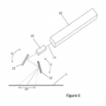
- the speed of a laser cutter can be increased beyond the speed achievable according to Figures 4 and 5 by using a galvo mirror cutting head mounted over the cutting table in place of the mirrors 12 and 13, the cutting head 7 and the rails 8 and 9 of Figure 1 .
- a galvo mirror cutting head is illustrated schematically in Figure 6 .
- the laser is again given the reference number 10, but the laser beam 11 is passed first through a dynamic focussing and collimating lens 20 and then reflected by pivotable mirrors 21 and 22.
- the pivotal axes of the two mirrors are mutually perpendicular, providing pivotal mirror movements to move the laser focus point in the X and Y directions.
- That pivoting movement of the two mirrors 21 and 22 is illustrated by double-headed arrows X and Y, resulting in a final range of movement of the focus point of the laser beam 11 indicated schematically by the double-headed arrow XY.
- the pivoting movement of the mirrors under the control of the cutting command data, can move the point of focus of the laser beam over the sheet material on the cutting table far more rapidly than the sliding cutting head control of Figures 4 and 5 , so significantly faster throughput of the sheet material is possible.
- the throughput through the machine of Figures 4 and 5 or the machine of Figure 6 can be increased even further by having more than one cutting head in each machine, so that more than one closed loop shape can be cut from the sheet material simultaneously.
Landscapes
- Engineering & Computer Science (AREA)
- Mechanical Engineering (AREA)
- Physics & Mathematics (AREA)
- Optics & Photonics (AREA)
- Life Sciences & Earth Sciences (AREA)
- Forests & Forestry (AREA)
- Plasma & Fusion (AREA)
- General Engineering & Computer Science (AREA)
- Computer Vision & Pattern Recognition (AREA)
- Treatment Of Fiber Materials (AREA)
- Laser Beam Processing (AREA)
Claims (13)
- Verfahren zum Programmieren und Betreiben einer numerisch gesteuerten Schneidemaschine, um sie zu veranlassen, Formen aus einem Blattmaterial (1) in Übereinstimmung mit Designs, einschließlich fortlaufender Liniendaten, auszuschneiden, welche auf diesem Blattmaterial (1) vorgedruckt wurden, wobei das Verfahren umfasst:Bewegen des Blattmaterials (1) aus einem Vorratsbehälter (2) des vorgedruckten Blattmaterials in einer Vorwärtsrichtung (3) an einer oder mehreren Kameras oder optischen Sensoren (6) vorbei und dann über einen Schneidetisch (4), wo die Formen geschnitten werden sollen;Verwenden der einen oder mehreren Kameras oder optischen Sensoren (6), um auf dem Blattmaterial (1) vorgedruckte Daten zu erfassen, während es sich in Richtung des Schneidetisches (4) bewegt;Verwenden nur der erfassten Daten, um neue Schneidebefehlsdaten zu berechnen, dadurch Erstellen von ausgerichteten Schneidebefehlsdaten, welche mit den auf dem Blattmaterial (1) vorgedruckten Daten ausgerichtet sind; undVerwenden der ausgerichteten Schneidebefehlsdaten zum Ausschneiden von Formen aus dem bedruckten Blattmaterial (1) auf dem Schneidetisch (4);DADURCH GEKENNZEICHNET, DASS das Blattmaterial (1) durch eine Schneidebefehlsberechnungszone (50) zwischen der einen oder den mehreren Kameras oder optischen Sensoren (6) und dem Schneidetisch (4) geführt wird, und dass in der Schneidebefehlsberechnungszone (50) die Schneidebefehlsdaten berechnet oder geändert werden, um die ausgerichteten Schneidebefehlsdaten abzuleiten, sodass eine enge Ausrichtung zwischen den zu schneidenden Formen und den auf dem Blattmaterial (1) vorgedruckten Daten hergestellt und aufrechterhalten wird, wenn das Blattmaterial (1) den Schneidetisch (4) erreicht.
- Verfahren nach Anspruch 1, wobei die ausgerichteten Schneidebefehlsdaten erstellt werden, während das Blattmaterial (1) durch die Schneidebefehlsberechnungszone (50) läuft, durch eine Folge von:Identifizieren der fortlaufenden Liniendaten aus den durch die eine oder mehreren Kameras oder optischen Sensoren (6) erfassten Daten,Identifizieren der Form und Position von geschlossenen Schleifenformen, welche auf dem Blattmaterial (1) vorgedruckt sind, anhand dieser fortlaufenden Liniendaten; undAbleiten von Schneidebefehlsdaten, welche in Form und Lage mit den identifizierten geschlossenen Schleifenformen übereinstimmen, welche auf dem Blattmaterial (1) vorgedruckt sind;und wobei die abgeleiteten ausgerichteten Schneidebefehlsdaten an die Schneidemaschine übertragen werden, um zu veranlassen, dass die Maschine die identifizierten geschlossenen Schleifenformen aus dem Blattmaterial (1) schneidet, wenn das Blattmaterial (1) anschließend über den Schneidetisch (4) läuft, wobei eine enge Ausrichtung zwischen den zu schneidenden Formen und den auf dem Blattmaterial (1) vorgedruckten Daten aufrechterhalten wird.
- Verfahren nach Anspruch 2, wobei der Datenverarbeitungsschritt Ignorieren aller geschlossenen Schleifenformen umfasst, welche innerhalb der Grenzen anderer größerer geschlossener Schleifenformen enthalten sind.
- Verfahren nach Anspruch 2, wobei der Datenverarbeitungsschritt Identifizieren von geschlossenen Schleifenformen umfasst, selbst wenn sie innerhalb der Grenzen anderer größerer geschlossener Schleifenformen enthalten sind.
- Verfahren nach einem der vorstehenden Ansprüche, wobei das Blattmaterial (1) ein flexibles Blattmaterial ist und der Vorratsbehälter (2) eine Rolle ist, von welcher das Blattmaterial (1) abgezogen und ständig in Vorwärtsrichtung (3) zu dem und über den Schneidetisch (4) bewegt wird.
- Verfahren nach einem der vorstehenden Ansprüche, wobei das Blattmaterial (1) durch die Schneidebefehlsberechnungszone (50) und über den Schneidetisch (4) durch einen perforierten Förderer transportiert wird, gegen welchen das Blattmaterial (1) durch Luftansaugung festgehalten wird.
- Numerisch gesteuerte Schneidemaschine, umfassend:Mittel zum Bewegen von Blattmaterial (1) aus einem Vorratsbehälter (2) mit vorgedrucktem Blattmaterial in einer konstanten Vorwärtsrichtung (3) zu einem und über einen Schneidetisch (4);eine oder mehrere Kameras oder optische Sensoren (6), welche direkt über dem Blattmaterial (1) angeordnet sind, während es von dem Vorratsbehälter (2) zu dem Schneidetisch (4) gelangt;Mittel zum Verwenden der einen oder mehreren Kameras oder optischen Sensoren (6), um auf dem Blattmaterial (1) vorgedruckte Daten zu erfassen;Mittel zum Verwenden nur der erfassten Daten, um Schneidebefehlsdaten zu berechnen, welche mit den auf dem Blattmaterial (1) vorgedruckten Daten ausgerichtet sind; undMittel zum Verwenden der ausgerichteten Schneidebefehlsdaten zum Ausschneiden von Formen aus dem bedruckten Blattmaterial (1) auf dem Schneidetisch (4);DADURCH GEKENNZEICHNET, DASSdie eine oder mehreren Kameras oder optischen Sensoren (6) relativ zu der Vorwärtsbewegung des Blattmaterials (1) vor dem Schneidetisch (4) positioniert und in der Vorwärtsrichtung (3) von dem Schneidetisch (4) durch eine Schneidebefehlsberechnungszone (50) getrennt sind; unddie Mittel zum Verwenden der erfassten Daten zum Berechnen der Schneidebefehlsdaten so programmiert sind, dass sie diese Berechnung durchführen, während das Blattmaterial (1) durch die Schneidebefehlsberechnungszone (50) läuft, ohne dass das Schneiden der Formen aus dem Blattmaterial (1), welches sich bereits auf dem Schneidetisch (4) befindet, unterbrochen wird.
- Maschine nach Anspruch 7, umfassend Mittel zum Berechnen der Schneidebefehlsdaten, während das Blattmaterial (1) durch die Schneidebefehlsberechnungszone (50) läuft, durch eine Folge von:(a) Identifizieren fortlaufender Liniendaten aus den durch die Ausgabe der einen oder mehreren Kameras oder optischen Sensoren (6) erfassten Daten; und(b) Verarbeiten der fortlaufenden Liniendaten, um die Form und Position von geschlossenen Schleifenformen zu identifizieren, welche auf dem Blattmaterial (1) vorgedruckt sind, und(c) Ableiten von ausgerichteten Schneidebefehlsdaten, welche so ausgerichtet sind, dass sie mit den identifizierten geschlossenen Schleifenformen übereinstimmen, welche auf dem Blattmaterial vorgedruckt sind (1).
- Maschine nach Anspruch 7 oder Anspruch 8, wobei der Schneidekopf ein Laserschneidekopf ist.
- Maschine nach Anspruch 7 oder Anspruch 8, wobei der Schneidekopf ein Spiegel-und Laserstrahl-Fokussierkopf ist, welcher auf einer Schiene über dem Schneidetisch (4) montiert ist, so dass er in X-Richtung entlang dieser Schiene hin und her verschiebbar ist, wobei die Schiene selbst zwischen einem Paar Schienen über dem Schneidetisch (4) montiert ist, sodass sie entlang dieser Schienen in Y-Richtung hin und her verschiebbar ist, weiter umfassend Mittel zum Antreiben des Schneidekopfs, welche wirksam sind, um ein Hin- und Herverschieben des Schneidekopfs in X- und Y-Richtung als Reaktion auf die abgeleiteten Schneidebefehlsdaten zu bewirken, um den Schneidekopf zu veranlassen, den auf dem Blattmaterial (1) gedruckten Formen zu folgen.
- Maschine nach Anspruch 7 oder Anspruch 8, wobei der Schneidekopf ein Laserstrahl-Galvo-Spiegel-Schneidekopf ist, welcher über dem Schneidetisch (4) montiert ist und ein Paar Spiegel einschließt, welche in einer oszillierenden Weise um zueinander senkrechte Schwenkachsen schwenken können, weiter umfassend Mittel zum Antreiben des Schneidekopfes, um zu bewirken, dass sich ein Fokuspunkt des Laserstrahls in X- und Y-Richtung über die Oberfläche des Blattmaterials (1) auf dem Schneidetisch (4) bewegt, um den auf dem Blattmaterial (1) gedruckten Formen zu folgen.
- Maschine nach einem der Ansprüche 7 bis 11, wobei das Mittel zum Bewegen des Blattmaterials (1) ein perforierter Förderer ist und die Luftansaugung durch die Perforationen in dem Förderer dazu dient, das Blattmaterial (1) nach unten gegen die obere Spannweite des Förderers zu ziehen, um es während der Bewegung des Blattmaterials (1) durch die Schneidebefehlsberechnungszone (50) und über den Schneidetisch (4) während des Ausschneidens der Formen fest auf dem Förderer zu halten.
- Maschine nach einem der Ansprüche 7 bis 12, wobei der Vorratsbehälter (2) Mittel zum Anbringen einer Rolle des Blattmaterials (1), bei welchem es sich um ein flexibles Blattmaterial handelt, Mittel zum Abziehen des Blattmaterials (1) von der Rolle und Mittel zum seitlichen Bewegen der Rolle umfasst, um eine glatte und faltenfreie Präsentation des Blattmaterials (1) auf dem Schneidetisch (4) aufrechtzuerhalten, wenn das Blattmaterial (1) von der Rolle abgezogen wird.
Applications Claiming Priority (1)
| Application Number | Priority Date | Filing Date | Title |
|---|---|---|---|
| GB1904937.8A GB2582923B (en) | 2019-04-08 | 2019-04-08 | Automatic cutting of shapes from sheet material |
Publications (3)
| Publication Number | Publication Date |
|---|---|
| EP3722044A1 EP3722044A1 (de) | 2020-10-14 |
| EP3722044C0 EP3722044C0 (de) | 2024-01-03 |
| EP3722044B1 true EP3722044B1 (de) | 2024-01-03 |
Family
ID=66809395
Family Applications (1)
| Application Number | Title | Priority Date | Filing Date |
|---|---|---|---|
| EP20163853.3A Active EP3722044B1 (de) | 2019-04-08 | 2020-03-18 | Automatisches schneiden von formen aus blattmaterial |
Country Status (2)
| Country | Link |
|---|---|
| EP (1) | EP3722044B1 (de) |
| GB (1) | GB2582923B (de) |
Families Citing this family (4)
| Publication number | Priority date | Publication date | Assignee | Title |
|---|---|---|---|---|
| US12059751B2 (en) * | 2020-03-27 | 2024-08-13 | Mitsubishi Electric Research Laboratories, Inc. | System and method for detecting and correcting laser-cutting distortion |
| CN115401339A (zh) * | 2022-10-21 | 2022-11-29 | 山东旭天标识工程有限公司 | 一种可自动拾取样本路径并切割的激光切割机及切割方法 |
| CN116125907B (zh) * | 2023-04-20 | 2024-01-30 | 沈阳和研科技股份有限公司 | 一种环切意外中断的续切方法 |
| CN119747907A (zh) * | 2024-11-27 | 2025-04-04 | 东莞市光博士激光科技股份有限公司 | 基于人工智能的布料激光切割方法、系统及介质 |
Family Cites Families (4)
| Publication number | Priority date | Publication date | Assignee | Title |
|---|---|---|---|---|
| GB9307421D0 (en) * | 1993-04-08 | 1993-06-02 | Cadcam Punch Ltd | Laser cutter |
| US9623578B1 (en) * | 2015-12-16 | 2017-04-18 | Amazon Technologies, Inc. | On demand apparel manufacturing |
| US9868302B1 (en) * | 2016-06-20 | 2018-01-16 | Amazon Technologies, Inc. | Fluorescent ink printing, cutting, and apparel assembly |
| IT201700079792A1 (it) * | 2017-07-14 | 2019-01-14 | Morgan Tecnica S P A | Metodo per la stampa e il taglio automatico di un foglio tessile |
-
2019
- 2019-04-08 GB GB1904937.8A patent/GB2582923B/en active Active
-
2020
- 2020-03-18 EP EP20163853.3A patent/EP3722044B1/de active Active
Also Published As
| Publication number | Publication date |
|---|---|
| GB2582923A (en) | 2020-10-14 |
| GB2582923B (en) | 2023-09-20 |
| EP3722044A1 (de) | 2020-10-14 |
| EP3722044C0 (de) | 2024-01-03 |
| GB201904937D0 (en) | 2019-05-22 |
Similar Documents
| Publication | Publication Date | Title |
|---|---|---|
| EP3722044A1 (de) | Automatisches schneiden von formen aus blattmaterial | |
| EP0693017B1 (de) | Schneidlaser | |
| US7070668B2 (en) | Method and apparatus for production of labels | |
| EP3260255B1 (de) | System zum schneiden von schneidgut | |
| US5791215A (en) | Method of cutting patterns out of patterned fabrics with a cutting apparatus which includes a scanning device | |
| US8295555B2 (en) | Systems and methods for processing of coverings such as leather hides and fabrics for furniture and other products | |
| JP2011087696A (ja) | 打刻データ作成装置及び打刻データ作成プログラム | |
| JP5419742B2 (ja) | 裁断装置及び裁断方法 | |
| US9019569B2 (en) | Image reading apparatus having multiple types of holding units and cutting apparatus | |
| US6830639B2 (en) | Method and apparatus for producing folded labels having rounded corners | |
| CN114178708A (zh) | 一种用于服装生产的激光刻花裁剪系统 | |
| JP2019136850A (ja) | 積層裁断方法と積層裁断システム | |
| US5806449A (en) | Method and apparatus for attaching sleeves to shirt bodies | |
| US20040026919A1 (en) | Method and apparatus for production of labels | |
| WO2016129491A1 (ja) | 切断装置及びアップリケ縫製方法 | |
| US20050061428A1 (en) | Method and apparatus for bonding an additional layer of fabric to a label | |
| US11473228B2 (en) | Non-transitory computer-readable medium and embroidery data generation method | |
| JP5800642B2 (ja) | 生地裁断方法及び生地裁断装置 | |
| JPH07255966A (ja) | 柄合せ自動玉縁縫い装置 |
Legal Events
| Date | Code | Title | Description |
|---|---|---|---|
| PUAI | Public reference made under article 153(3) epc to a published international application that has entered the european phase |
Free format text: ORIGINAL CODE: 0009012 |
|
| STAA | Information on the status of an ep patent application or granted ep patent |
Free format text: STATUS: THE APPLICATION HAS BEEN PUBLISHED |
|
| AK | Designated contracting states |
Kind code of ref document: A1 Designated state(s): AL AT BE BG CH CY CZ DE DK EE ES FI FR GB GR HR HU IE IS IT LI LT LU LV MC MK MT NL NO PL PT RO RS SE SI SK SM TR |
|
| AX | Request for extension of the european patent |
Extension state: BA ME |
|
| STAA | Information on the status of an ep patent application or granted ep patent |
Free format text: STATUS: REQUEST FOR EXAMINATION WAS MADE |
|
| 17P | Request for examination filed |
Effective date: 20210301 |
|
| RBV | Designated contracting states (corrected) |
Designated state(s): AL AT BE BG CH CY CZ DE DK EE ES FI FR GB GR HR HU IE IS IT LI LT LU LV MC MK MT NL NO PL PT RO RS SE SI SK SM TR |
|
| RAP1 | Party data changed (applicant data changed or rights of an application transferred) |
Owner name: SUMMA NV Owner name: CADCAM TECHNOLOGY LIMITED |
|
| REG | Reference to a national code |
Ref country code: DE Ref legal event code: R079 Free format text: PREVIOUS MAIN CLASS: B23K0026080000 Ipc: B26F0003120000 Ref country code: DE Ref legal event code: R079 Ref document number: 602020023661 Country of ref document: DE Free format text: PREVIOUS MAIN CLASS: B23K0026080000 Ipc: B26F0003120000 |
|
| GRAP | Despatch of communication of intention to grant a patent |
Free format text: ORIGINAL CODE: EPIDOSNIGR1 |
|
| STAA | Information on the status of an ep patent application or granted ep patent |
Free format text: STATUS: GRANT OF PATENT IS INTENDED |
|
| RIC1 | Information provided on ipc code assigned before grant |
Ipc: B23K 26/38 20060101ALI20230117BHEP Ipc: B23K 103/00 20060101ALI20230117BHEP Ipc: B23K 26/08 20060101ALI20230117BHEP Ipc: B26D 5/00 20060101ALI20230117BHEP Ipc: B26F 1/38 20060101ALI20230117BHEP Ipc: B26F 3/06 20060101ALI20230117BHEP Ipc: B26F 3/12 20060101AFI20230117BHEP |
|
| INTG | Intention to grant announced |
Effective date: 20230131 |
|
| RIN1 | Information on inventor provided before grant (corrected) |
Inventor name: DIAZ DIAZ, SIMEON MICHAEL Inventor name: MOONEY, ROBERT WILLIAM Inventor name: LAW, ROGER DESMOND Inventor name: WHITE, DAVID MICHAEL |
|
| GRAJ | Information related to disapproval of communication of intention to grant by the applicant or resumption of examination proceedings by the epo deleted |
Free format text: ORIGINAL CODE: EPIDOSDIGR1 |
|
| STAA | Information on the status of an ep patent application or granted ep patent |
Free format text: STATUS: REQUEST FOR EXAMINATION WAS MADE |
|
| INTC | Intention to grant announced (deleted) | ||
| GRAP | Despatch of communication of intention to grant a patent |
Free format text: ORIGINAL CODE: EPIDOSNIGR1 |
|
| STAA | Information on the status of an ep patent application or granted ep patent |
Free format text: STATUS: GRANT OF PATENT IS INTENDED |
|
| INTG | Intention to grant announced |
Effective date: 20230725 |
|
| GRAS | Grant fee paid |
Free format text: ORIGINAL CODE: EPIDOSNIGR3 |
|
| GRAA | (expected) grant |
Free format text: ORIGINAL CODE: 0009210 |
|
| STAA | Information on the status of an ep patent application or granted ep patent |
Free format text: STATUS: THE PATENT HAS BEEN GRANTED |
|
| AK | Designated contracting states |
Kind code of ref document: B1 Designated state(s): AL AT BE BG CH CY CZ DE DK EE ES FI FR GB GR HR HU IE IS IT LI LT LU LV MC MK MT NL NO PL PT RO RS SE SI SK SM TR |
|
| REG | Reference to a national code |
Ref country code: GB Ref legal event code: FG4D |
|
| REG | Reference to a national code |
Ref country code: CH Ref legal event code: EP |
|
| REG | Reference to a national code |
Ref country code: DE Ref legal event code: R096 Ref document number: 602020023661 Country of ref document: DE |
|
| REG | Reference to a national code |
Ref country code: IE Ref legal event code: FG4D |
|
| U01 | Request for unitary effect filed |
Effective date: 20240117 |
|
| U07 | Unitary effect registered |
Designated state(s): AT BE BG DE DK EE FI FR IT LT LU LV MT NL PT SE SI Effective date: 20240201 |
|
| U20 | Renewal fee for the european patent with unitary effect paid |
Year of fee payment: 5 Effective date: 20240131 |
|
| PG25 | Lapsed in a contracting state [announced via postgrant information from national office to epo] |
Ref country code: ES Free format text: LAPSE BECAUSE OF FAILURE TO SUBMIT A TRANSLATION OF THE DESCRIPTION OR TO PAY THE FEE WITHIN THE PRESCRIBED TIME-LIMIT Effective date: 20240103 |
|
| PG25 | Lapsed in a contracting state [announced via postgrant information from national office to epo] |
Ref country code: ES Free format text: LAPSE BECAUSE OF FAILURE TO SUBMIT A TRANSLATION OF THE DESCRIPTION OR TO PAY THE FEE WITHIN THE PRESCRIBED TIME-LIMIT Effective date: 20240103 |
|
| PG25 | Lapsed in a contracting state [announced via postgrant information from national office to epo] |
Ref country code: IS Free format text: LAPSE BECAUSE OF FAILURE TO SUBMIT A TRANSLATION OF THE DESCRIPTION OR TO PAY THE FEE WITHIN THE PRESCRIBED TIME-LIMIT Effective date: 20240503 |
|
| PG25 | Lapsed in a contracting state [announced via postgrant information from national office to epo] |
Ref country code: GR Free format text: LAPSE BECAUSE OF FAILURE TO SUBMIT A TRANSLATION OF THE DESCRIPTION OR TO PAY THE FEE WITHIN THE PRESCRIBED TIME-LIMIT Effective date: 20240404 |
|
| PG25 | Lapsed in a contracting state [announced via postgrant information from national office to epo] |
Ref country code: RS Free format text: LAPSE BECAUSE OF FAILURE TO SUBMIT A TRANSLATION OF THE DESCRIPTION OR TO PAY THE FEE WITHIN THE PRESCRIBED TIME-LIMIT Effective date: 20240403 Ref country code: HR Free format text: LAPSE BECAUSE OF FAILURE TO SUBMIT A TRANSLATION OF THE DESCRIPTION OR TO PAY THE FEE WITHIN THE PRESCRIBED TIME-LIMIT Effective date: 20240103 |
|
| PG25 | Lapsed in a contracting state [announced via postgrant information from national office to epo] |
Ref country code: CZ Free format text: LAPSE BECAUSE OF FAILURE TO SUBMIT A TRANSLATION OF THE DESCRIPTION OR TO PAY THE FEE WITHIN THE PRESCRIBED TIME-LIMIT Effective date: 20240103 |
|
| PG25 | Lapsed in a contracting state [announced via postgrant information from national office to epo] |
Ref country code: RS Free format text: LAPSE BECAUSE OF FAILURE TO SUBMIT A TRANSLATION OF THE DESCRIPTION OR TO PAY THE FEE WITHIN THE PRESCRIBED TIME-LIMIT Effective date: 20240403 Ref country code: NO Free format text: LAPSE BECAUSE OF FAILURE TO SUBMIT A TRANSLATION OF THE DESCRIPTION OR TO PAY THE FEE WITHIN THE PRESCRIBED TIME-LIMIT Effective date: 20240403 Ref country code: IS Free format text: LAPSE BECAUSE OF FAILURE TO SUBMIT A TRANSLATION OF THE DESCRIPTION OR TO PAY THE FEE WITHIN THE PRESCRIBED TIME-LIMIT Effective date: 20240503 Ref country code: HR Free format text: LAPSE BECAUSE OF FAILURE TO SUBMIT A TRANSLATION OF THE DESCRIPTION OR TO PAY THE FEE WITHIN THE PRESCRIBED TIME-LIMIT Effective date: 20240103 Ref country code: GR Free format text: LAPSE BECAUSE OF FAILURE TO SUBMIT A TRANSLATION OF THE DESCRIPTION OR TO PAY THE FEE WITHIN THE PRESCRIBED TIME-LIMIT Effective date: 20240404 Ref country code: CZ Free format text: LAPSE BECAUSE OF FAILURE TO SUBMIT A TRANSLATION OF THE DESCRIPTION OR TO PAY THE FEE WITHIN THE PRESCRIBED TIME-LIMIT Effective date: 20240103 |
|
| PG25 | Lapsed in a contracting state [announced via postgrant information from national office to epo] |
Ref country code: PL Free format text: LAPSE BECAUSE OF FAILURE TO SUBMIT A TRANSLATION OF THE DESCRIPTION OR TO PAY THE FEE WITHIN THE PRESCRIBED TIME-LIMIT Effective date: 20240103 |
|
| PG25 | Lapsed in a contracting state [announced via postgrant information from national office to epo] |
Ref country code: PL Free format text: LAPSE BECAUSE OF FAILURE TO SUBMIT A TRANSLATION OF THE DESCRIPTION OR TO PAY THE FEE WITHIN THE PRESCRIBED TIME-LIMIT Effective date: 20240103 |
|
| REG | Reference to a national code |
Ref country code: DE Ref legal event code: R097 Ref document number: 602020023661 Country of ref document: DE |
|
| PG25 | Lapsed in a contracting state [announced via postgrant information from national office to epo] |
Ref country code: SM Free format text: LAPSE BECAUSE OF FAILURE TO SUBMIT A TRANSLATION OF THE DESCRIPTION OR TO PAY THE FEE WITHIN THE PRESCRIBED TIME-LIMIT Effective date: 20240103 |
|
| PG25 | Lapsed in a contracting state [announced via postgrant information from national office to epo] |
Ref country code: SK Free format text: LAPSE BECAUSE OF FAILURE TO SUBMIT A TRANSLATION OF THE DESCRIPTION OR TO PAY THE FEE WITHIN THE PRESCRIBED TIME-LIMIT Effective date: 20240103 |
|
| PG25 | Lapsed in a contracting state [announced via postgrant information from national office to epo] |
Ref country code: SM Free format text: LAPSE BECAUSE OF FAILURE TO SUBMIT A TRANSLATION OF THE DESCRIPTION OR TO PAY THE FEE WITHIN THE PRESCRIBED TIME-LIMIT Effective date: 20240103 Ref country code: SK Free format text: LAPSE BECAUSE OF FAILURE TO SUBMIT A TRANSLATION OF THE DESCRIPTION OR TO PAY THE FEE WITHIN THE PRESCRIBED TIME-LIMIT Effective date: 20240103 Ref country code: RO Free format text: LAPSE BECAUSE OF FAILURE TO SUBMIT A TRANSLATION OF THE DESCRIPTION OR TO PAY THE FEE WITHIN THE PRESCRIBED TIME-LIMIT Effective date: 20240103 |
|
| REG | Reference to a national code |
Ref country code: CH Ref legal event code: PL |
|
| PLBE | No opposition filed within time limit |
Free format text: ORIGINAL CODE: 0009261 |
|
| STAA | Information on the status of an ep patent application or granted ep patent |
Free format text: STATUS: NO OPPOSITION FILED WITHIN TIME LIMIT |
|
| PG25 | Lapsed in a contracting state [announced via postgrant information from national office to epo] |
Ref country code: MC Free format text: LAPSE BECAUSE OF FAILURE TO SUBMIT A TRANSLATION OF THE DESCRIPTION OR TO PAY THE FEE WITHIN THE PRESCRIBED TIME-LIMIT Effective date: 20240103 |
|
| PG25 | Lapsed in a contracting state [announced via postgrant information from national office to epo] |
Ref country code: MC Free format text: LAPSE BECAUSE OF FAILURE TO SUBMIT A TRANSLATION OF THE DESCRIPTION OR TO PAY THE FEE WITHIN THE PRESCRIBED TIME-LIMIT Effective date: 20240103 |
|
| 26N | No opposition filed |
Effective date: 20241007 |
|
| PG25 | Lapsed in a contracting state [announced via postgrant information from national office to epo] |
Ref country code: IE Free format text: LAPSE BECAUSE OF NON-PAYMENT OF DUE FEES Effective date: 20240318 |
|
| PG25 | Lapsed in a contracting state [announced via postgrant information from national office to epo] |
Ref country code: IE Free format text: LAPSE BECAUSE OF NON-PAYMENT OF DUE FEES Effective date: 20240318 Ref country code: CH Free format text: LAPSE BECAUSE OF NON-PAYMENT OF DUE FEES Effective date: 20240331 |
|
| U20 | Renewal fee for the european patent with unitary effect paid |
Year of fee payment: 6 Effective date: 20250217 |
|
| PG25 | Lapsed in a contracting state [announced via postgrant information from national office to epo] |
Ref country code: CY Free format text: LAPSE BECAUSE OF FAILURE TO SUBMIT A TRANSLATION OF THE DESCRIPTION OR TO PAY THE FEE WITHIN THE PRESCRIBED TIME-LIMIT; INVALID AB INITIO Effective date: 20200318 |
|
| PG25 | Lapsed in a contracting state [announced via postgrant information from national office to epo] |
Ref country code: HU Free format text: LAPSE BECAUSE OF FAILURE TO SUBMIT A TRANSLATION OF THE DESCRIPTION OR TO PAY THE FEE WITHIN THE PRESCRIBED TIME-LIMIT; INVALID AB INITIO Effective date: 20200318 |
|
| PG25 | Lapsed in a contracting state [announced via postgrant information from national office to epo] |
Ref country code: TR Free format text: LAPSE BECAUSE OF FAILURE TO SUBMIT A TRANSLATION OF THE DESCRIPTION OR TO PAY THE FEE WITHIN THE PRESCRIBED TIME-LIMIT Effective date: 20240103 |
|
| U20 | Renewal fee for the european patent with unitary effect paid |
Year of fee payment: 7 Effective date: 20260202 |
|
| PGFP | Annual fee paid to national office [announced via postgrant information from national office to epo] |
Ref country code: GB Payment date: 20260202 Year of fee payment: 7 |