EP3722009A1 - Device and system - Google Patents
Device and system Download PDFInfo
- Publication number
- EP3722009A1 EP3722009A1 EP20164573.6A EP20164573A EP3722009A1 EP 3722009 A1 EP3722009 A1 EP 3722009A1 EP 20164573 A EP20164573 A EP 20164573A EP 3722009 A1 EP3722009 A1 EP 3722009A1
- Authority
- EP
- European Patent Office
- Prior art keywords
- nozzle
- lacquer
- limiting means
- channel
- transfer roller
- Prior art date
- Legal status (The legal status is an assumption and is not a legal conclusion. Google has not performed a legal analysis and makes no representation as to the accuracy of the status listed.)
- Withdrawn
Links
- 239000004922 lacquer Substances 0.000 claims abstract description 150
- 239000012528 membrane Substances 0.000 claims description 3
- 230000000694 effects Effects 0.000 description 11
- 238000006073 displacement reaction Methods 0.000 description 5
- 239000011888 foil Substances 0.000 description 3
- 239000011241 protective layer Substances 0.000 description 3
- 230000001681 protective effect Effects 0.000 description 2
- 239000000758 substrate Substances 0.000 description 2
- 239000011248 coating agent Substances 0.000 description 1
- 238000000576 coating method Methods 0.000 description 1
- 238000009826 distribution Methods 0.000 description 1
- 238000004049 embossing Methods 0.000 description 1
- 239000012530 fluid Substances 0.000 description 1
- 238000009434 installation Methods 0.000 description 1
- 239000007788 liquid Substances 0.000 description 1
- 230000000873 masking effect Effects 0.000 description 1
- 229920001296 polysiloxane Polymers 0.000 description 1
- 238000012805 post-processing Methods 0.000 description 1
- 238000002360 preparation method Methods 0.000 description 1
- 238000005096 rolling process Methods 0.000 description 1
- 230000007704 transition Effects 0.000 description 1
- 238000009827 uniform distribution Methods 0.000 description 1
Images




Classifications
-
- B—PERFORMING OPERATIONS; TRANSPORTING
- B05—SPRAYING OR ATOMISING IN GENERAL; APPLYING FLUENT MATERIALS TO SURFACES, IN GENERAL
- B05C—APPARATUS FOR APPLYING FLUENT MATERIALS TO SURFACES, IN GENERAL
- B05C1/00—Apparatus in which liquid or other fluent material is applied to the surface of the work by contact with a member carrying the liquid or other fluent material, e.g. a porous member loaded with a liquid to be applied as a coating
- B05C1/04—Apparatus in which liquid or other fluent material is applied to the surface of the work by contact with a member carrying the liquid or other fluent material, e.g. a porous member loaded with a liquid to be applied as a coating for applying liquid or other fluent material to work of indefinite length
- B05C1/08—Apparatus in which liquid or other fluent material is applied to the surface of the work by contact with a member carrying the liquid or other fluent material, e.g. a porous member loaded with a liquid to be applied as a coating for applying liquid or other fluent material to work of indefinite length using a roller or other rotating member which contacts the work along a generating line
- B05C1/0813—Apparatus in which liquid or other fluent material is applied to the surface of the work by contact with a member carrying the liquid or other fluent material, e.g. a porous member loaded with a liquid to be applied as a coating for applying liquid or other fluent material to work of indefinite length using a roller or other rotating member which contacts the work along a generating line characterised by means for supplying liquid or other fluent material to the roller
-
- B—PERFORMING OPERATIONS; TRANSPORTING
- B05—SPRAYING OR ATOMISING IN GENERAL; APPLYING FLUENT MATERIALS TO SURFACES, IN GENERAL
- B05C—APPARATUS FOR APPLYING FLUENT MATERIALS TO SURFACES, IN GENERAL
- B05C1/00—Apparatus in which liquid or other fluent material is applied to the surface of the work by contact with a member carrying the liquid or other fluent material, e.g. a porous member loaded with a liquid to be applied as a coating
- B05C1/02—Apparatus in which liquid or other fluent material is applied to the surface of the work by contact with a member carrying the liquid or other fluent material, e.g. a porous member loaded with a liquid to be applied as a coating for applying liquid or other fluent material to separate articles
-
- B—PERFORMING OPERATIONS; TRANSPORTING
- B05—SPRAYING OR ATOMISING IN GENERAL; APPLYING FLUENT MATERIALS TO SURFACES, IN GENERAL
- B05C—APPARATUS FOR APPLYING FLUENT MATERIALS TO SURFACES, IN GENERAL
- B05C1/00—Apparatus in which liquid or other fluent material is applied to the surface of the work by contact with a member carrying the liquid or other fluent material, e.g. a porous member loaded with a liquid to be applied as a coating
- B05C1/04—Apparatus in which liquid or other fluent material is applied to the surface of the work by contact with a member carrying the liquid or other fluent material, e.g. a porous member loaded with a liquid to be applied as a coating for applying liquid or other fluent material to work of indefinite length
- B05C1/08—Apparatus in which liquid or other fluent material is applied to the surface of the work by contact with a member carrying the liquid or other fluent material, e.g. a porous member loaded with a liquid to be applied as a coating for applying liquid or other fluent material to work of indefinite length using a roller or other rotating member which contacts the work along a generating line
- B05C1/0808—Details thereof, e.g. surface characteristics
-
- B—PERFORMING OPERATIONS; TRANSPORTING
- B05—SPRAYING OR ATOMISING IN GENERAL; APPLYING FLUENT MATERIALS TO SURFACES, IN GENERAL
- B05C—APPARATUS FOR APPLYING FLUENT MATERIALS TO SURFACES, IN GENERAL
- B05C1/00—Apparatus in which liquid or other fluent material is applied to the surface of the work by contact with a member carrying the liquid or other fluent material, e.g. a porous member loaded with a liquid to be applied as a coating
- B05C1/04—Apparatus in which liquid or other fluent material is applied to the surface of the work by contact with a member carrying the liquid or other fluent material, e.g. a porous member loaded with a liquid to be applied as a coating for applying liquid or other fluent material to work of indefinite length
- B05C1/08—Apparatus in which liquid or other fluent material is applied to the surface of the work by contact with a member carrying the liquid or other fluent material, e.g. a porous member loaded with a liquid to be applied as a coating for applying liquid or other fluent material to work of indefinite length using a roller or other rotating member which contacts the work along a generating line
- B05C1/0821—Apparatus in which liquid or other fluent material is applied to the surface of the work by contact with a member carrying the liquid or other fluent material, e.g. a porous member loaded with a liquid to be applied as a coating for applying liquid or other fluent material to work of indefinite length using a roller or other rotating member which contacts the work along a generating line characterised by driving means for rollers or work
-
- B—PERFORMING OPERATIONS; TRANSPORTING
- B05—SPRAYING OR ATOMISING IN GENERAL; APPLYING FLUENT MATERIALS TO SURFACES, IN GENERAL
- B05C—APPARATUS FOR APPLYING FLUENT MATERIALS TO SURFACES, IN GENERAL
- B05C1/00—Apparatus in which liquid or other fluent material is applied to the surface of the work by contact with a member carrying the liquid or other fluent material, e.g. a porous member loaded with a liquid to be applied as a coating
- B05C1/04—Apparatus in which liquid or other fluent material is applied to the surface of the work by contact with a member carrying the liquid or other fluent material, e.g. a porous member loaded with a liquid to be applied as a coating for applying liquid or other fluent material to work of indefinite length
- B05C1/08—Apparatus in which liquid or other fluent material is applied to the surface of the work by contact with a member carrying the liquid or other fluent material, e.g. a porous member loaded with a liquid to be applied as a coating for applying liquid or other fluent material to work of indefinite length using a roller or other rotating member which contacts the work along a generating line
- B05C1/0873—Controlling means responsive to conditions of the liquid or other fluent material, of the ambient medium, of the roller or of the work
- B05C1/0886—Controlling means responsive to conditions of the liquid or other fluent material, of the ambient medium, of the roller or of the work responsive to the condition of the work
-
- B—PERFORMING OPERATIONS; TRANSPORTING
- B05—SPRAYING OR ATOMISING IN GENERAL; APPLYING FLUENT MATERIALS TO SURFACES, IN GENERAL
- B05C—APPARATUS FOR APPLYING FLUENT MATERIALS TO SURFACES, IN GENERAL
- B05C11/00—Component parts, details or accessories not specifically provided for in groups B05C1/00 - B05C9/00
- B05C11/10—Storage, supply or control of liquid or other fluent material; Recovery of excess liquid or other fluent material
- B05C11/1002—Means for controlling supply, i.e. flow or pressure, of liquid or other fluent material to the applying apparatus, e.g. valves
- B05C11/1005—Means for controlling supply, i.e. flow or pressure, of liquid or other fluent material to the applying apparatus, e.g. valves responsive to condition of liquid or other fluent material already applied to the surface, e.g. coating thickness, weight or pattern
-
- B—PERFORMING OPERATIONS; TRANSPORTING
- B05—SPRAYING OR ATOMISING IN GENERAL; APPLYING FLUENT MATERIALS TO SURFACES, IN GENERAL
- B05C—APPARATUS FOR APPLYING FLUENT MATERIALS TO SURFACES, IN GENERAL
- B05C21/00—Accessories or implements for use in connection with applying liquids or other fluent materials to surfaces, not provided for in groups B05C1/00 - B05C19/00
-
- B—PERFORMING OPERATIONS; TRANSPORTING
- B05—SPRAYING OR ATOMISING IN GENERAL; APPLYING FLUENT MATERIALS TO SURFACES, IN GENERAL
- B05C—APPARATUS FOR APPLYING FLUENT MATERIALS TO SURFACES, IN GENERAL
- B05C5/00—Apparatus in which liquid or other fluent material is projected, poured or allowed to flow on to the surface of the work
- B05C5/02—Apparatus in which liquid or other fluent material is projected, poured or allowed to flow on to the surface of the work the liquid or other fluent material being discharged through an outlet orifice by pressure, e.g. from an outlet device in contact or almost in contact, with the work
- B05C5/0254—Coating heads with slot-shaped outlet
- B05C5/0262—Coating heads with slot-shaped outlet adjustable in width, i.e. having lips movable relative to each other in order to modify the slot width, e.g. to close it
-
- B—PERFORMING OPERATIONS; TRANSPORTING
- B05—SPRAYING OR ATOMISING IN GENERAL; APPLYING FLUENT MATERIALS TO SURFACES, IN GENERAL
- B05C—APPARATUS FOR APPLYING FLUENT MATERIALS TO SURFACES, IN GENERAL
- B05C9/00—Apparatus or plant for applying liquid or other fluent material to surfaces by means not covered by any preceding group, or in which the means of applying the liquid or other fluent material is not important
- B05C9/08—Apparatus or plant for applying liquid or other fluent material to surfaces by means not covered by any preceding group, or in which the means of applying the liquid or other fluent material is not important for applying liquid or other fluent material and performing an auxiliary operation
- B05C9/12—Apparatus or plant for applying liquid or other fluent material to surfaces by means not covered by any preceding group, or in which the means of applying the liquid or other fluent material is not important for applying liquid or other fluent material and performing an auxiliary operation the auxiliary operation being performed after the application
-
- B—PERFORMING OPERATIONS; TRANSPORTING
- B05—SPRAYING OR ATOMISING IN GENERAL; APPLYING FLUENT MATERIALS TO SURFACES, IN GENERAL
- B05D—PROCESSES FOR APPLYING FLUENT MATERIALS TO SURFACES, IN GENERAL
- B05D1/00—Processes for applying liquids or other fluent materials
- B05D1/28—Processes for applying liquids or other fluent materials performed by transfer from the surfaces of elements carrying the liquid or other fluent material, e.g. brushes, pads, rollers
-
- B—PERFORMING OPERATIONS; TRANSPORTING
- B05—SPRAYING OR ATOMISING IN GENERAL; APPLYING FLUENT MATERIALS TO SURFACES, IN GENERAL
- B05D—PROCESSES FOR APPLYING FLUENT MATERIALS TO SURFACES, IN GENERAL
- B05D5/00—Processes for applying liquids or other fluent materials to surfaces to obtain special surface effects, finishes or structures
Definitions
- the invention relates to a device and a system for a lacquer transfer.
- a device for a lacquer transfer is known from the publication WO 2015/155 128 A1 .
- This publication discloses a device which is configured for transferring lacquer to a surface of a work piece.
- the work piece may be formed by a part of an aircraft, motor vehicle, boat or any other object.
- the work piece may therefore be referred to as an object.
- the work piece may be a part of an aircraft, for instance a wing of an aircraft.
- the surface of the work piece may be referred to as a substrate surface.
- the device may be referred to as an applicator.
- the device comprises a frame, a transfer roller with a circumferential lateral wall and a drive unit. An outside contact surface of the lateral wall comprises several depressions.
- the device has its own drive for a circumferential movement of the transfer roller.
- the transfer roller is mounted rotatably about an axis of rotation at the frame.
- the device can be connected to a robot arm and moved via the robot arm in parallel to the surface of the work piece, such that the transfer roller rolls with its contact surface on a surface of the work piece for transferring lacquer from the depressions in the lateral wall of the transfer roller to the surface of the work piece.
- the depressions of the lateral wall have to be filled with the lacquer, such that the lacquer can be transferred subsequently to the surface of the work piece while the transfer rollers rolls on this surface.
- an object When transferring lacquer via the device to a surface of a substrate, an object is to transfer a desired or predetermined amount of a lacquer to the surface of the work piece.
- the surface of the work piece may comprise areas, which should not be coated with lacquer. These areas are called non-application areas or lacquer-free areas.
- these areas may be masked in advance via protective foils, sicker or similar protective layers, which can be removed after transferring the lacquer via the device.
- protective foils, sicker or similar protective layers which can be removed after transferring the lacquer via the device.
- An object of the present invention is to provide a device and a system which is configured for transferring a controllable quantity of lacquer via a transfer roller to a surface of a work piece.
- the object is solved by a device with the features of claim 1.
- the invention relates to a device for a lacquer transfer.
- the device comprises a frame, a transfer roller with a circumferential lateral wall, a drive unit and a slit nozzle.
- the slit nozzle is at least indirectly connected to the frame.
- An outside contact surface of the lateral wall comprises several depressions.
- the transfer roller is mounted rotatably about an axis of rotation at the frame, wherein the drive unit is configured to drive the transfer roller such that the transfer roller rotates about the axis of rotation.
- the slit nozzle comprises a supply connection, a nozzle-cavity, a slit-shaped nozzle-channel and at least one limiting means.
- the supply connection is coupled to the nozzle-cavity for supplying lacquer to the nozzle-cavity, wherein nozzle-channel extends from the nozzle-cavity to a muzzle-end, which is formed by the slit nozzle at the end of the nozzle-channel and configured for dispensing lacquer.
- the slit nozzle is configured by means of the at least one limiting means to adjust a cross-section in a restriction area of the nozzle-channel.
- the muzzle-end of the slit nozzle is arranged contactless or in direct contact with the outside contact surface for dispensing lacquer into respective depressions.
- the transfer roller is configured to roll with the outside contact surface on a work surface of a work piece for transferring the lacquer from the depressions to the work surface of the work piece.
- the device or at least its frame is configured to be releasably connected to a handling device, such as a robot with a robot arm.
- the frame may be configured to be releasably connected to the robot arm.
- the device may be a mobile device, in particular a mobile mechanical device.
- the frame may form the basis of the device, since the slit nozzle is at least indirectly connected to the frame.
- the device may comprise further connecting means for connecting the slit nozzle to the frame.
- the slit nozzle may be mounted and/or releasably connected to the frame.
- the transfer roller is mounted rotatably at the frame.
- the transfer roller can therefore rotate about the axis of rotation.
- the device comprises the drive unit, which is configured to drive the transfer roller in a rotation direction of the transfer roller about the axis of rotation.
- the drive unit may also be at least indirectly connected or mounted to the frame.
- the drive unit drives the transfer roller, such that the transfer roller rotates about the axis of rotation and rolls with the contact surface on a work surface.
- the device is moved translational in parallel to the work surface, preferably by a robot arm or another handling device, while the transfer roller rotates, such that the transfer roller rolls on the work surface for transferring lacquer.
- the supply connection of the slit nozzle may be connected via a pipe or a tube to a lacquer supply unit, which may be configured to supply the lacquer via the tube or the pipe to the slit nozzle.
- the lacquer may be a self-hardening lacquer or a lacquer, which can be hardened via UV-light.
- the lacquer supplied to the slit nozzle may be a liquid medium or a viscous medium.
- the muzzle end of the slit nozzle may be arranged contactless to the outside contact surface of the lateral wall for dispensing lacquer into respective depressions.
- the muzzle end of the slit nozzle is arranged in direct contact with the outside contact surface of the lateral wall for dispensing lacquer into respective depressions.
- the corresponding explanations may, in principle, apply as preferred embodiments to each of the two arrangements. Therefore, it may be possible to apply the respective explanations to one of the first and second nozzle arrangement or to both nozzle arrangements.
- the slit nozzle is configured for dispensing lacquer into the depressions of the lateral wall of the transfer roller.
- the slit nozzle may also be configured for dispensing lacquer onto depression-free sections of the lateral wall of the transfer roller.
- the slit nozzle may be configured for dispensing a lacquer film onto the lateral wall of the transfer roller, wherein the lacquer of the lacquer film fills the depressions and the lacquer film extends in axial direction and partly in circumferential direction of the transfer roller.
- the lacquer film may therefore theoretically divide into a depression part, which fills the depressions, and a remaining part, which is also referred to as bulk or a bulk part.
- the transfer roller may be configured to roll with the contact surface of the transfer roller on a work surface of a work piece for transferring the lacquer from the contact surface to the work surface of the work piece, such that the lacquer film is transferred to the work surface.
- a work piece may comprise areas, which should not be coated with lacquer. These areas are called non-application areas. Further, the work piece may comprise areas, where only a very limited amount of lacquer is to be transferred. It is therefore desirable, to adjust the amount of lacquer to be transferred to specific areas of the surface of the work piece.
- the slit nozzle comprises a supply connection, a nozzle-cavity, a slit-shaped-nozzle-channel and at least one limiting means.
- the supply connection of the slit nozzle may be connected via a pipe or tube to a lacquer supply unit. Therefore, the lacquer may be pumped from the lacquer supply unit via the pipe or tube to the supply connection of the slit nozzle.
- the supply connection of the slit nozzle is coupled to the nozzle-cavity for supplying lacquer to the nozzle-cavity.
- the nozzle-cavity is therefore filled with lacquer.
- the nozzle-channel extends from the nozzle-cavity to a muzzle end.
- the muzzle end is formed at the end of the nozzle-channel by the slit nozzle.
- the muzzle end may therefore be formed at least partly by the nozzle-channel.
- the muzzle end is configured for dispensing lacquer provided by the nozzle-channel.
- the slit nozzle is configured by means of at least one limiting means for adjusting a cross-section in a restriction area of the nozzle-channel.
- the restriction area of the nozzle-channel may be arranged at an a predefined position between the one end of the muzzle channel at the nozzle-cavity or the other end of the nozzle-channel at the muzzle end.
- the restriction area may be a limited area of the nozzle-channel.
- the at least one limiting means may be configured to limit and/or reduce the cross-section in the restriction area of the nozzle-channel.
- the at least one limiting means may be formed by mechanical means, which can be moved into the nozzle-channel, such that the cross-section is reduced by a part of the limiting means extending into the nozzle-channel.
- the at least one limiting means may be a controllable limiting means.
- the at least one limiting means may be connected to a control unit for controlling the position of the at least one limiting means.
- the control unit may be a part of the device.
- the at least one limiting means may therefore be controlled to adjust the cross-section in the restriction area of the nozzle-channel according to a reference signal, which represents a desired cross-section in the restriction area of the nozzle-channel.
- the control unit may comprise an input interface for receiving the reference signal.
- the cross-section in the restriction area of the nozzle-channel can be adjusted during use.
- the cross-section may be limited or closed, such that a little or no lacquer flows through the nozzle-channel, respectively. This may be used, when the transfer roller comes close to a non-application area of the work piece. For instance, if the non-application area of the surface of the work piece should not be covered with lacquer, the at least one limiting means is controlled to close the nozzle-channel at a time interval, when no lacquer is to be transferred to the transfer roller.
- the time interval, when no lacquer is dispensed onto the outside contact surface of the transfer roller, is timed, such that the transfer roller does not transfer lacquer onto the non-application area of the surface of the workpiece. Consequently, the non-application area of the surface of the work piece does not need to be protected via foils, sticker or similar protective layers in advance. Instead, the transfer of the lacquer can be prevented for the respective non-application areas of the surface of the work piece with the at least one limiting means of the slit nozzle. This reduces the effort for preparation required for the transfer of lacquer to the work piece and the subsequent post-processing effort. Moreover, the device allows to reduce the lacquer consumption. The device also enables to reduce the lead time and enables to improve the transition between areas, where lacquer is to be transferred and the non-application areas.
- the at least one limiting means is configured to be displaced to reduce the cross-section in the restriction area of the nozzle-channel.
- the at least one limiting means may therefore be displaced into the nozzle-channel resulting in the reduction of the cross-section of the nozzle-channel.
- the at least one limiting means may also be displaced in the opposite direction, such that the cross-section of the nozzle-channel is enlarged (again).
- the at least one limiting means may be configured to be displaced between a first position and a second position. In the first position, the at least one limiting means may be arranged, such that the cross-section in the restriction area of the nozzle-channel represents a maximum cross-section.
- the at least one limiting means In a second position, the at least one limiting means may be arranged, such that the cross-section of the nozzle-channel is less than the maximum cross-section.
- the at least one limiting means may be in the first position, if the transfer roller is not heading a non-application area. However, if the transfer roller is heading a non-application area, the at least one limiting means may be displaced to be in the second position, such that the cross-section is limited or even closed.
- the at least one limiting means is arranged at the muzzle end of the nozzle-channel. Therefore, the at least one limiting means may be arranged at the front end of the nozzle-channel. This allows a precise adjustment of the flow rate of the lacquer through the nozzle-channel and therefore allows to precisely adjust the flow of lacquer to be dispensed by the muzzle end onto the outside contact surface of the transfer roller.
- the at least one limiting means is arranged between the muzzle end and the nozzle-cavity. Lacquer flowing from the nozzle-cavity through the nozzle-channel to be dispensed by the muzzle end of the nozzle-channel can therefore be precisely adjusted with the at least one limiting means arranged between the muzzle end and the nozzle-cavity.
- the at least one limiting means is arranged to precisely adjust the cross-section in the restriction of the nozzle-channel, wherein this restriction area is also between the muzzle end and the nozzle-cavity.
- the device comprises an actuator unit, which is at least indirectly connected to the at least one limiting means and configured to displace the at least one limiting means.
- the actuator unit can actively displace the at least one limiting means, such that the cross-section in the restriction area of the nozzle-channel is adjusted according to a predetermined or predefined value.
- the cross-section may be actively reduced or closed with the actuator unit by displacing the at least one limiting unit, such that the at least one limiting unit extends partly or fully into the nozzle-channel.
- the actuator unit may be a controllable actuator unit.
- the actuator unit may be an air driven, fluid driven or electrically driven actuator unit.
- the slit nozzle comprises at least two limiting means.
- the slit nozzle comprises more than two limiting means, preferably at least four limiting means. Therefore, the slit nozzle may comprise several limiting means.
- the flow of lacquer through the nozzle-channel can be limited in its cross-section differently with respect to the width. For instance, the cross-section on a left side of the nozzle-channel may be limited to a further extent than by another limiting means of the right hand side of the nozzle-channel.
- the cross section of the nozzle-channel may be adjusted differently on different positions with respect to the width of the nozzle-channel.
- the nozzle-channel may be limited with respect to its cross-section only in a sub-area of the restriction area of the nozzle-channel.
- lacquer may not flow through this sub-area of the nozzle-channel and therefore does not dispense in a respective area lacquer on the transfer roller.
- the transfer roller may only be subject to a respective transfer of lacquer from the slit-nozzle to its contact surface such that a part of the transfer roller remains free from lacquer. This may be of advantage, if only the respective part of the transfer roller is heading a non-application area on the surface of the work piece.
- the limiting means are arranged in alignment one behind the other in the direction of a width of the nozzle-channel.
- the direction of the width is parallel to the axis of rotation of the transfer roller.
- Each of the limiting means may be displaced to reduce a sub-cross-section of the whole cross-section in the restriction area of the nozzle-channel.
- each of the respective sub-cross-sections may be individually adjusted by a displacement of the corresponding limiting means. For instance, if the cross-section is supposed to be closed on the left side, the limiting means arranged on the left side of the slit nozzle may be displaced to close the cross-section of the left hand side.
- the two limiting means on the left side may be displaced to extend into the nozzle-channel, such that their associated sub-cross-sections are reduced closed.
- the slit nozzle may not dispense lacquer on the left side and the transfer roller may not be able to transfer lacquer for a time period while the respective limiting means are partly closing the nozzle-channel.
- the transfer roller is heading a non-application area with its left side.
- the transfer roller may be free of a lacquer film on the left side of the transfer roller, such that this lacquer-film-free transfer roller is rolling over the non-application area.
- the limiting means may be displaced in order to enlarge the cross-section of the nozzle-channel to its full amount.
- the actuator unit of the device comprises for each limiting means an associated actuator, which is configured to individually displace the associated limiting means.
- each of the limiting means may be individually displaced by controlling the respective actuator of the actuator unit.
- the actuators associated to the two limiting means on the left side may be controlled, such that the two limiting means on the left side are displaced to close the respective sub-sections of the nozzle-channel.
- this embodiment is not limiting the general concept of the invention.
- another of the limiting means may be achieved.
- all limiting means may be displaced in parallel.
- the limiting means may be displaced, such that each of the limiting means extends the same distance into the nozzle-channel.
- each of the actuators may be controlled individually. Therefore, the displacement of each of the limiting means may be controlled individually.
- the limiting means are formed by rods, flaps, lever arms, membranes, inflatable bellows or inflatable tubes.
- rods or flaps have been found to be of advantage.
- each limiting means may be formed by a rod.
- the rods may be arranged one behind the other in direction of the width of the nozzle-channel.
- the rods may be arranged, such that no gap is between the rods.
- the rods may be displaced to extend partly or fully into the nozzle-channel, such that any particular cross-section may be formed by the displacement of the rods.
- the cross-section may be fully or partly closed.
- the cross-section is only partly closed, this may refer to a sub-section on the left or right side or even in the middle of the nozzle channel. But if the rods are displaced uniformly, only the lower-sub-section of the nozzle-channel may be remained open. Similar effects can be achieved if the limiting means are each formed by flaps, lever arms, membranes, inflatable bellows or inflatable tubes.
- the slit nozzle comprises exact one limiting means formed by a nozzle-part of the slit nozzle, wherein the nozzle-channel is at least partly formed by the nozzle-part.
- the slit nozzle may comprise at the nozzle channel a lower nozzle-part, which can be displaced towards the nozzle-channel such that the cross-section of the nozzle-channel is reduced.
- the slit nozzle may therefore comprise an upper part and a lower part which form the nozzle-channel, wherein the lower part may be displaced towards the upper part, in order to reduce the cross-section of the nozzle-channel.
- the nozzle-channel may be closed, if the lower part is displaced fully towards the upper part.
- the object is solved by a device with the features according to claim 11. Therefore, the invention also relates to a system for a lacquer transfer.
- the system comprises a device according to the first aspect of the present invention or according to one of the preferred embodiments of the device described above.
- the system also comprises a sensor, which is configured to detect a thickness of the lacquer.
- the system also comprises a control unit.
- the sensor of the system is connected to the control unit to transmit a sensor signal to the control unit, which sensor signal represents the detected thickness of the lacquer.
- the control unit is connected to the actuator unit of the device, such that the actuator unit is controllable via the control unit.
- the control unit is configured to control the actuator unit of the device based on the detected thickness of the lacquer. Since the system can detect the thickness of the lacquer via the sensor and control the control unit of the device via the control unit, the system may be configured to implement a closed loop control for controlling the thickness of the lacquer. As an effect, a precise thickness of the lacquer can be transferred to the surface of the work piece.
- the senor of the system is arranged to detect the thickness of the lacquer on the outside contact surface of the lateral wall of the transfer roller.
- the detector may be arranged to detect the thickness of the lacquer just behind the slit nozzle, such that the thickness of the lacquer can be detected even before it is transferred to the surface of the work piece.
- the sensor of the system is arranged to detect the thickness of the lacquer transferred to the work surface of the work piece. For instance, if the frame of the device is moved in a transfer direction while the transfer roller rolls on the surface of the work piece, the sensor may be mounted to the frame at a position behind the transfer roller, such that the sensor can detect the thickness of the lacquer transferred to the surface of the work piece. This allows to precisely control the thickness of the lacquer transfer to the surface of the work piece.
- the control unit is configured to control each actuator of the actuator unit individually. For instance, if the transfer roller of the device is heading a non-application area of the surface of the work piece, it may be sufficient to prevent that a part in width-direction of the transfer roller is not transferring lacquer via the transfer roller while it rolls above the non-application area on the surface of the work piece. To achieve that said part in width-direction of the transfer roller is not dispensed with lacquer via the device, the control unit may control the actuators of the actuator unit, such that only those actuators displace the associated limiting means, such that these limiting means close their respective sub-cross-sections.
- the control unit may control the actuators again after the transfer roller is about to pass or already passed the non-application area on the surface of the work piece.
- the non-application areas of the surface of the work piece do not have to be covered for preventing lacquer to be transferred to the non-application areas.
- Figure 1 schematically illustrates an aircraft 52, which comprises a fuselage 54 and a wing 56.
- the air resistance of the aircraft 52 can be reduced, if the upper wing surface 58 of the wing 56 comprises a profile structure. It has been found of advantage, if this profile structure is a microstructure.
- Figure 1 also schematically shows a robot 60, which is seated on a rack 62.
- the robot 60 comprises a movable robot arm 64.
- a device 2 is mounted at an end of the robot arm 64, such that the device 2 can be moved by the robot 60.
- the device 2 is configured for transferring a lacquer onto a work surface 30 of a work piece 32.
- the work piece 32 can be formed by the wing 56 of the aircraft 52.
- the upper wing surface 58 can form the work surface 30.
- a first embodiment of the device 2 is schematically illustrated in figure 2 in a cross-sectional view.
- the device 2 comprises a frame 4, a transfer roller 6 with a circumferential lateral wall 8, a drive unit 10 and a slit nozzle 12.
- the transfer roller 6 may also be referred to as a transfer tire.
- the device 2 can be attached via the frame 4 to the robot arm 64.
- any other handling device may also be used, which is configured to move the device 2 in space.
- the frame 4 may be adapted to be releasably connected to a handling device, such as the robot 60.
- the transfer roller 6 is mounted rotatably, in particular by means of at least one bearing, about an axis of rotation A at the frame 4.
- An outside contact surface 14 of the lateral wall 8 comprises several depressions 16.
- the depressions 16 may be evenly or stochastically distributed about the circumference of the lateral wall 8.
- the figures 3 and 4 show a part of the transfer roller 6 in a cross-section view and a top view, respectively.
- the depressions 16 can be formed by recesses arranged at the outside contact surface 14 of the lateral wall 8 of the transfer roller 6.
- the depressions 16 may have a predefined size and/or structure.
- a mean structure size of the depressions 16 can be in the range of 0,1 micrometer to 100 micrometer. In other words, each of the depressions 16 may have a microstructure.
- Figure 4 exemplarily shows the depressions 16 of a part of the lateral wall 8 of the transfer roller 6 in a top view.
- Each of the depressions 16 may comprise an elongated extension in a circumferential direction U of the lateral wall 8 of the transfer roller 6.
- Each of the depressions 16 is configured to receive lacquer and to transfer this received lacquer to a work surface 30 of a work piece 32, such as the upper wing surface 58 of a wing 56. Therefore, the several depressions 16 at the outside contact surface 14 of the lateral wall 8 may be arranged and/or formed according to a predefined structure, in particular a predefined microstructure.
- the lateral wall 8 is preferably made of silicone, such that a damage of the wing surface 58 can be prevented.
- the muzzle end 26 of the slit nozzle 12 is arranged close to but contactless with the outside contact surface 14 of the lateral wall 8 for dispensing lacquer from the muzzle end 26 into respective depressions 16.
- the muzzle end 26 of the slit nozzle 12 may be alternatively arranged in direct contact with the outside contact surface 14 of the lateral wall 8 for dispensing lacquer into the depressions 16.
- the depressions 16 of the lateral wall 8 arranged are therefore filled with lacquer.
- the transfer roller 6 is driven by the drive unit 10, such that the transfer roller 6 rotates about the axis of rotation A.
- the lacquer is transported via the depressions 16 in rotation direction K such that the outside contact surface 14 with the depressions 16 filled with lacquer rolls in direct contact about the work surface 30 of the work piece 32 for transferring the lacquer to the work surface 30.
- the lacquer may be transferred to the wing surface 58 of the wing 56 of the aircraft 52.
- the lacquer previously received in the depressions 16 is transferred to the work surface 30, in particular the wing surface 58 of the aircraft 52.
- This transferred lacquer has a structure, in particular microstructure, corresponding to a structure defined by depressions 16.
- the outside contact surface 14 with its depressions 16 is configured for embossing a lacquer-structure, in particular a lacquer-microstructure, on the work surface 30, in particular the wing surface 58.
- microstructure lacquer is applied to the wing surface 58 of an aircraft wing 56.
- the aircraft wing 56 may comprise areas at the wing surface 58, which are not to be painted with lacquer. These areas are referred to as non-application areas 66 and schematically indicated in Figures 6 and 8 . Both Figures 6 and 8 show a part of the wing surface 58 of the aircraft wing 56.
- the non-application areas 66 may form a section of the wing surface 58 of the aircraft wing 56, however, the non-application areas 66 are supposed to be free of a lacquer coating.
- the device 2 is configured to interrupt the transfer of lacquer to the wing surface 58 in the non-application areas 66 while the transfer roller rolls above the aircraft wing 56.
- the slit nozzle 12 of the device 2 comprises a nozzle-cavity 20, a slit-shaped nozzle-channel 22 and at least one limiting means 24.
- the nozzle-channel 22 extends from the nozzle-cavity 20 to a muzzle end 26, which is formed by the slit nozzle 12 at the end of the nozzle-channel 22 and configured for dispensing lacquer.
- the slit nozzle 12 also comprises a supply connection 18.
- the supply connection 18 may be connected via a pipe or tube to a lacquer supply unit (which is not shown).
- the lacquer supply unit can pump lacquer into the nozzle-cavity 20, such that the lacquer flows through the nozzle-channel 22 resulting in the dispensing of the lacquer at the muzzle end 26, such that the lacquer is applied to the outside contact surface 14 of the lateral wall 8 of the transfer roller 6.
- the amount of lacquer dispensed via the slit nozzle 12 into the outside contact surface 14 depends on the size of the cross-section 28 of the nozzle-channel 22.
- the amount of lacquer may depend on the smallest cross-section 28 of the nozzle-channel 22. Therefore, in the following referenc is made to the cross-section 28 in a restriction area of the nozzle-channel 22.
- the cross-section 28 in the restriction area of the nozzle-channel 22 preferably refers to the smallest cross-section 28 of the nozzle-channel 22.
- the slit nozzle 12 is therefore configured by means of at least one limiting mean 24 to adjust the cross-section 28 in a restriction area of the nozzle-channel 22.
- Figure 5 shows an embodiment of a cross-section 28 in view of the slit nozzle 12.
- the limiting means 24 of the slit nozzle 12 may be configured to be displaced in a direction perpendicular to the width and/or the flow direction of lacquer through the nozzle-channel 22.
- the cross-section 28 of the nozzle-channel 22 can be adjusted by a displacement of the limiting means 24.
- the slit nozzle 12 comprises a plurality of limiting means 24, which are arranged in alignment one behind the other in the direction W of the width of the nozzle-channel 22.
- the direction W of width of the nozzle-channel 22 is parallel to the axis of rotation A.
- the slit nozzle 12 preferably comprises an actuator unit 34 which comprises several actuators 36.
- the actuator unit 34 preferably comprises for each limiting means 24 an associated actuator 36, which is configured to individually displace the associated limiting means 24.
- the actuator unit 34 in particular its actuators 36 may be controlled, such that the limiting means 24 are displaced in parallel to enlarge or reduce the size of the cross-section 28 of the nozzle-channel 22. Therefore, even if the flow rate through the nozzle-channel 22 may be increased or reduced, the distribution with respect to the width W may remain uniform.
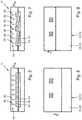
- non-application areas 66 are often arranged, such that only subsections of the transfer roller 6 with respect to its width are to be interrupted in its transfer of lacquer. It has therefore been found of advantage, that the limiting means 24 may be displaced individually, as it is indicated in Figure 7 .
- the position of the transfer roller 6 in contact with the wing surface 58 of the aircraft wing 56 is indicated with the dashed line in Figures 6 and 8 . If the device 2 is moved into the driving direction F, the transfer roller 6 may reach a position in front of at least one non-application area 66.
- the actuator unit 34 may be controlled, for example, such that the third and the sixth actuator 36 are displaced, such that the associated limiting means 24 fully close a corresponding sub-section of the nozzle-channel 22. This is indicated in Figure 7 .
- a strip on the outside contact surface 14 is not dispensed with lacquer via the slit nozzle 12.
- This lacquer-free-strip on the outside contact surface 14 will roll over the non-application area 66 of the aircraft surface, while the transfer roller 6 is rotated about the axis of rotation A. Since the lacquer-free-strip does not transfer lacquer on the non-application area 66, this non-application area 66 does not have to be masked in advance or even being clean afterwards. The effort is therefore significantly reduced.
- the actuator unit 34 in particular in connection with its actuator 36 may be configured to displace each of the limiting means 24 according to reference signal.
- FIG. 11 Examples of possible embodiments of the limiting means 24 are schematically shown in Figures 11 and 12 .
- the limiting means 24 indicated in Figure 11 are formed by rods 38.
- the limiting means 24 indicated in Figure 22 are formed by flaps 40.
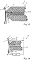
- FIG. 13 Another embodiment of the limiting means 24 is schematically shown in Figure 13 , which shows a part of the device 2 and its slit nozzle 12.
- the limiting means 24 may be formed by inflatable tubes 42. These tubes 42 may be inflated in order to adjust the size of the cross-section 28 of the nozzle-channel 22.
- the limiting means 24 may be displaceable arranged in an upper part of the slit nozzle 12. Moreover, the limiting means 24 may be arranged at a nose section of the slit nozzle 12.
- the limiting means 24 may be arranged between the muzzle end 26 and the nozzle-cavity 20, such that the limiting means 24 can adjust the cross-section 28 in a restriction area of the nozzle-channel 22.
- FIG. 10 Another embodiment of the device 2 is schematically shown in Figure 10 .
- the limiting means 24 are displaceable arranged in a lower part of the slit nozzle 12, such that the limiting means 24 can be displaced towards or away from the lateral wall 8 of the transfer roller 6.
- the effective cross-section 28 of the nozzle-channel 22 between the nozzle-cavity 20 in the muzzle end 26 can be adjusted.
- the device 2 may comprise a hardening unit 70.
- the hardening unit 70 is configured for hardening the lacquer, preferably contactless.
- the hardening unit 70 can be formed by an UV-light unit.
- the hardening unit 70 is directly or indirectly connected to the frame 4.
- the hardening unit 70 can be arranged within the interior space 68 formed by the transfer roller 6.
- the lateral wall 8 of the transfer roller 6 may be configured to transmit UV-light-waves.
- the lateral wall 8 can be transparent for UV-light.
- the hardening unit 70 can be arranged, such that UV-light is emitted towards a work surface 30 upon which the lateral wall 8 of the transfer roller 6 can roll.
- the lacquer may be hardenable via UV-light. Therefore, the device 2 may be configured to control the drive unit 10 and/or the UV-light unit, such that lacquer transferred to the work surface 30 is immediately hardened via UV-light emitted by the UV-light unit.
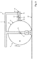
- the system 46 comprises a device 2. Furthermore, the system 46 comprises a sensor 48, which is configured to detecting thickness of the lacquer. The system 46 also comprises a control unit 50. The sensor 48 is connected, preferably via a signal line, to the control unit 50 to transmit a sensor signal to the control unit 50, wherein the sensor signal represents a detected thickness of the lacquer. According to a preferred embodiment, the sensor 48 may be arranged, such that the sensor 48 can detect the thickness of the lacquer on the outside contact surface 14 of the lateral wall 8 of a transfer roller 6. For instance, the sensor 48 can be mounted to the slit nozzle 12, such that the thickness of the dispensed lacquer on the outside contact surface 14 can directly be detected. The sensor 48 may be configured to detect the thickness contactless.
- the control unit 50 is configured to control the actuator unit 34 of the device 2 based on the detected thickness of the lacquer.
- the control unit 50 may have access to a reference value, which represents a reference thickness for the lacquer to be dispensed on the outside contact surface 14 of the lateral wall 8.
- the detected thickness of the lacquer on the outside contact surface 14 is also provided to the control unit 50.
- the control unit 50 may be configured to compare the reference thickness with the detected thickness and based on the result of the comparison in particular depending on the respective error, the control unit 50 may control the actuator unit 34, such that its actuators 36 displaced the associated limiting means 24 in order to reach a thickness for the lacquer D on the outside contact surface 14, which corresponds to the reference thickness.
- the control unit 50 may be configured to control each of the actuators 36 of the actuator unit 34 individually.
- the senor 48 may be arranged differently, such that the sensor 48 is arranged to detect the thickness of the lacquer transferred to the work surface 30 of the work piece 32. But in general, the previous explanations apply in an analogous manner.
Landscapes
- Coating Apparatus (AREA)
Abstract
The invention relates to a device (2) for a lacquer transfer, comprising a frame (4), a transfer roller (6) with a circumferential lateral wall (8), a drive unit (10), a slit nozzle (12), wherein the slit nozzle (12) is at least indirectly connected to the frame (4), wherein an outside contact surface (14) of the lateral wall (8) comprises several depressions (16), wherein the transfer roller (6) is mounted rotatably about an axis of rotation (A) at the frame (4), wherein the drive unit (10) is configured to drive the transfer roller (6) such that the transfer roller (6) rotates about the axis of rotation (A), wherein the slit nozzle (12) comprises a supply connection (18), a nozzle-cavity (20), a slit-shaped nozzle-channel (22) and at least one limiting means (24), wherein the supply connection (18) is coupled to the nozzle-cavity (20) for supplying lacquer to the nozzle-cavity (20), wherein nozzle-channel (22) extends from the nozzle-cavity (20) to a muzzle end (26), which is formed by the slit nozzle (12) at the end of the nozzle-channel (22) and configured for dispensing lacquer, wherein the slit nozzle (12) is configured by means of the at least one limiting means (24) to adjust a cross-section (28) in a restriction area of the nozzle-channel (22), wherein the muzzle end (26) of the slit nozzle (12) is arranged contactless or in direct contact with the outside contact surface (14) for dispensing lacquer into respective depressions (16), and wherein the transfer roller (6) is configured to roll with the outside contact surface (14) on a work surface (30) of a work piece (32) for transferring the lacquer from the depressions (16) to the work surface (30) of the work piece (32). The invention also relates to a system (46) with a device (2).
Description
- The invention relates to a device and a system for a lacquer transfer.
- A device for a lacquer transfer is known from the publication
WO 2015/155 128 A1 . This publication discloses a device which is configured for transferring lacquer to a surface of a work piece. The work piece may be formed by a part of an aircraft, motor vehicle, boat or any other object. The work piece may therefore be referred to as an object. In an example, the work piece may be a part of an aircraft, for instance a wing of an aircraft. The surface of the work piece may be referred to as a substrate surface. The device may be referred to as an applicator. The device comprises a frame, a transfer roller with a circumferential lateral wall and a drive unit. An outside contact surface of the lateral wall comprises several depressions. Furthermore, the device has its own drive for a circumferential movement of the transfer roller. The transfer roller is mounted rotatably about an axis of rotation at the frame. The device can be connected to a robot arm and moved via the robot arm in parallel to the surface of the work piece, such that the transfer roller rolls with its contact surface on a surface of the work piece for transferring lacquer from the depressions in the lateral wall of the transfer roller to the surface of the work piece. Before the contact surface of the circumferential lateral wall of the transfer roller comes into contact with the surface of the work piece, the depressions of the lateral wall have to be filled with the lacquer, such that the lacquer can be transferred subsequently to the surface of the work piece while the transfer rollers rolls on this surface. - When transferring lacquer via the device to a surface of a substrate, an object is to transfer a desired or predetermined amount of a lacquer to the surface of the work piece. But the surface of the work piece may comprise areas, which should not be coated with lacquer. These areas are called non-application areas or lacquer-free areas. To protect the non-application areas during the transfer of the lacquer via the known device, these areas may be masked in advance via protective foils, sicker or similar protective layers, which can be removed after transferring the lacquer via the device. However, the previous installation of protective foils, sicker or similar protective layers and the subsequent removal results in a high effort, which should be avoided.
- An object of the present invention is to provide a device and a system which is configured for transferring a controllable quantity of lacquer via a transfer roller to a surface of a work piece. According to a first aspect of the invention, the object is solved by a device with the features of claim 1. In this context, the invention relates to a device for a lacquer transfer. The device comprises a frame, a transfer roller with a circumferential lateral wall, a drive unit and a slit nozzle. The slit nozzle is at least indirectly connected to the frame. An outside contact surface of the lateral wall comprises several depressions. The transfer roller is mounted rotatably about an axis of rotation at the frame, wherein the drive unit is configured to drive the transfer roller such that the transfer roller rotates about the axis of rotation. The slit nozzle comprises a supply connection, a nozzle-cavity, a slit-shaped nozzle-channel and at least one limiting means. The supply connection is coupled to the nozzle-cavity for supplying lacquer to the nozzle-cavity, wherein nozzle-channel extends from the nozzle-cavity to a muzzle-end, which is formed by the slit nozzle at the end of the nozzle-channel and configured for dispensing lacquer. The slit nozzle is configured by means of the at least one limiting means to adjust a cross-section in a restriction area of the nozzle-channel. The muzzle-end of the slit nozzle is arranged contactless or in direct contact with the outside contact surface for dispensing lacquer into respective depressions. The transfer roller is configured to roll with the outside contact surface on a work surface of a work piece for transferring the lacquer from the depressions to the work surface of the work piece.
- Preferably, the device or at least its frame is configured to be releasably connected to a handling device, such as a robot with a robot arm. The frame may be configured to be releasably connected to the robot arm. Thus, the device may be a mobile device, in particular a mobile mechanical device.
- The frame may form the basis of the device, since the slit nozzle is at least indirectly connected to the frame. For this purpose, the device may comprise further connecting means for connecting the slit nozzle to the frame. Thus, the slit nozzle may be mounted and/or releasably connected to the frame.
- The transfer roller is mounted rotatably at the frame. The transfer roller can therefore rotate about the axis of rotation. For this purpose, the device comprises the drive unit, which is configured to drive the transfer roller in a rotation direction of the transfer roller about the axis of rotation. The drive unit may also be at least indirectly connected or mounted to the frame. During use, the drive unit drives the transfer roller, such that the transfer roller rotates about the axis of rotation and rolls with the contact surface on a work surface. Furthermore, the device is moved translational in parallel to the work surface, preferably by a robot arm or another handling device, while the transfer roller rotates, such that the transfer roller rolls on the work surface for transferring lacquer.
- The supply connection of the slit nozzle may be connected via a pipe or a tube to a lacquer supply unit, which may be configured to supply the lacquer via the tube or the pipe to the slit nozzle. The lacquer may be a self-hardening lacquer or a lacquer, which can be hardened via UV-light. The lacquer supplied to the slit nozzle may be a liquid medium or a viscous medium.
- According to a first nozzle arrangement of the slit nozzle, the muzzle end of the slit nozzle may be arranged contactless to the outside contact surface of the lateral wall for dispensing lacquer into respective depressions.
- According to a second nozzle arrangement of the slit nozzle, the muzzle end of the slit nozzle is arranged in direct contact with the outside contact surface of the lateral wall for dispensing lacquer into respective depressions.
- If reference is subsequently made to the slit nozzle without explicitly specifying the first or second nozzle arrangement, the corresponding explanations may, in principle, apply as preferred embodiments to each of the two arrangements. Therefore, it may be possible to apply the respective explanations to one of the first and second nozzle arrangement or to both nozzle arrangements.
- The slit nozzle is configured for dispensing lacquer into the depressions of the lateral wall of the transfer roller. The slit nozzle may also be configured for dispensing lacquer onto depression-free sections of the lateral wall of the transfer roller. Thus, the slit nozzle may be configured for dispensing a lacquer film onto the lateral wall of the transfer roller, wherein the lacquer of the lacquer film fills the depressions and the lacquer film extends in axial direction and partly in circumferential direction of the transfer roller. The lacquer film may therefore theoretically divide into a depression part, which fills the depressions, and a remaining part, which is also referred to as bulk or a bulk part. Therefore, the transfer roller may be configured to roll with the contact surface of the transfer roller on a work surface of a work piece for transferring the lacquer from the contact surface to the work surface of the work piece, such that the lacquer film is transferred to the work surface. This encompasses the transfer of the lacquer from the depressions, but also the transfer of the bulk part. If the transfer of the lacquer from the depressions to the work surface, in particular to a surface of a wing, is described in the following, this shall preferable not exclude the possible transfer of the bulk part to the respective surface and/or the possible transfer of the lacquer from the depressions via the lacquer film.
- As explained in the introduction, a work piece may comprise areas, which should not be coated with lacquer. These areas are called non-application areas. Further, the work piece may comprise areas, where only a very limited amount of lacquer is to be transferred. It is therefore desirable, to adjust the amount of lacquer to be transferred to specific areas of the surface of the work piece. For this purpose, the slit nozzle comprises a supply connection, a nozzle-cavity, a slit-shaped-nozzle-channel and at least one limiting means. The supply connection of the slit nozzle may be connected via a pipe or tube to a lacquer supply unit. Therefore, the lacquer may be pumped from the lacquer supply unit via the pipe or tube to the supply connection of the slit nozzle. The supply connection of the slit nozzle is coupled to the nozzle-cavity for supplying lacquer to the nozzle-cavity. The nozzle-cavity is therefore filled with lacquer. The nozzle-channel extends from the nozzle-cavity to a muzzle end. The muzzle end is formed at the end of the nozzle-channel by the slit nozzle. The muzzle end may therefore be formed at least partly by the nozzle-channel. The muzzle end is configured for dispensing lacquer provided by the nozzle-channel. As a result, lacquer supplied via the supply connection and the nozzle-cavity to the nozzle-channel flows through the nozzle-channel and is dispensed at the end of the nozzle-channel via the muzzle end. The slit nozzle is configured by means of at least one limiting means for adjusting a cross-section in a restriction area of the nozzle-channel. The restriction area of the nozzle-channel may be arranged at an a predefined position between the one end of the muzzle channel at the nozzle-cavity or the other end of the nozzle-channel at the muzzle end. The restriction area may be a limited area of the nozzle-channel. There is at least one limiting means which can adjust the cross-section in the restriction area of the nozzle-channel, such that the cross-section is reduced. As a result, less lacquer can flow through the nozzle-channel, such that less lacquer is dispensed by the slit nozzle to the transfer roller. Therefore, the at least one limiting means may be configured to limit and/or reduce the cross-section in the restriction area of the nozzle-channel. The at least one limiting means may be formed by mechanical means, which can be moved into the nozzle-channel, such that the cross-section is reduced by a part of the limiting means extending into the nozzle-channel. The at least one limiting means may be a controllable limiting means. The at least one limiting means may be connected to a control unit for controlling the position of the at least one limiting means. The control unit may be a part of the device.The at least one limiting means may therefore be controlled to adjust the cross-section in the restriction area of the nozzle-channel according to a reference signal, which represents a desired cross-section in the restriction area of the nozzle-channel. The control unit may comprise an input interface for receiving the reference signal.
- As an effect, the cross-section in the restriction area of the nozzle-channel can be adjusted during use. For example, the cross-section may be limited or closed, such that a little or no lacquer flows through the nozzle-channel, respectively. This may be used, when the transfer roller comes close to a non-application area of the work piece. For instance, if the non-application area of the surface of the work piece should not be covered with lacquer, the at least one limiting means is controlled to close the nozzle-channel at a time interval, when no lacquer is to be transferred to the transfer roller. Preferably, the time interval, when no lacquer is dispensed onto the outside contact surface of the transfer roller, is timed, such that the transfer roller does not transfer lacquer onto the non-application area of the surface of the workpiece. Consequently, the non-application area of the surface of the work piece does not need to be protected via foils, sticker or similar protective layers in advance. Instead, the transfer of the lacquer can be prevented for the respective non-application areas of the surface of the work piece with the at least one limiting means of the slit nozzle. This reduces the effort for preparation required for the transfer of lacquer to the work piece and the subsequent post-processing effort. Moreover, the device allows to reduce the lacquer consumption. The device also enables to reduce the lead time and enables to improve the transition between areas, where lacquer is to be transferred and the non-application areas.
- According to a preferred embodiment of the device, the at least one limiting means is configured to be displaced to reduce the cross-section in the restriction area of the nozzle-channel. The at least one limiting means may therefore be displaced into the nozzle-channel resulting in the reduction of the cross-section of the nozzle-channel. The at least one limiting means may also be displaced in the opposite direction, such that the cross-section of the nozzle-channel is enlarged (again). The at least one limiting means may be configured to be displaced between a first position and a second position. In the first position, the at least one limiting means may be arranged, such that the cross-section in the restriction area of the nozzle-channel represents a maximum cross-section. In a second position, the at least one limiting means may be arranged, such that the cross-section of the nozzle-channel is less than the maximum cross-section. As an effect, the at least one limiting means may be in the first position, if the transfer roller is not heading a non-application area. However, if the transfer roller is heading a non-application area, the at least one limiting means may be displaced to be in the second position, such that the cross-section is limited or even closed.
- According to a further preferred embodiment of the device, the at least one limiting means is arranged at the muzzle end of the nozzle-channel. Therefore, the at least one limiting means may be arranged at the front end of the nozzle-channel. This allows a precise adjustment of the flow rate of the lacquer through the nozzle-channel and therefore allows to precisely adjust the flow of lacquer to be dispensed by the muzzle end onto the outside contact surface of the transfer roller.
- According to a further preferred embodiment of the device, the at least one limiting means is arranged between the muzzle end and the nozzle-cavity. Lacquer flowing from the nozzle-cavity through the nozzle-channel to be dispensed by the muzzle end of the nozzle-channel can therefore be precisely adjusted with the at least one limiting means arranged between the muzzle end and the nozzle-cavity. The at least one limiting means is arranged to precisely adjust the cross-section in the restriction of the nozzle-channel, wherein this restriction area is also between the muzzle end and the nozzle-cavity.
- According to a preferred embodiment of the device, the device comprises an actuator unit, which is at least indirectly connected to the at least one limiting means and configured to displace the at least one limiting means. As an effect, the actuator unit can actively displace the at least one limiting means, such that the cross-section in the restriction area of the nozzle-channel is adjusted according to a predetermined or predefined value. For instance, the cross-section may be actively reduced or closed with the actuator unit by displacing the at least one limiting unit, such that the at least one limiting unit extends partly or fully into the nozzle-channel. The actuator unit may be a controllable actuator unit. For instance, the actuator unit may be an air driven, fluid driven or electrically driven actuator unit.
- According to a preferred embodiment, the slit nozzle comprises at least two limiting means. According to a further embodiment of the device, the slit nozzle comprises more than two limiting means, preferably at least four limiting means. Therefore, the slit nozzle may comprise several limiting means. As a result, the flow of lacquer through the nozzle-channel can be limited in its cross-section differently with respect to the width. For instance, the cross-section on a left side of the nozzle-channel may be limited to a further extent than by another limiting means of the right hand side of the nozzle-channel. Thus, the cross section of the nozzle-channel may be adjusted differently on different positions with respect to the width of the nozzle-channel. As an effect, the nozzle-channel may be limited with respect to its cross-section only in a sub-area of the restriction area of the nozzle-channel. As a result, lacquer may not flow through this sub-area of the nozzle-channel and therefore does not dispense in a respective area lacquer on the transfer roller. As an effect, the transfer roller may only be subject to a respective transfer of lacquer from the slit-nozzle to its contact surface such that a part of the transfer roller remains free from lacquer. This may be of advantage, if only the respective part of the transfer roller is heading a non-application area on the surface of the work piece.
- According to a preferred embodiment of the device, the limiting means are arranged in alignment one behind the other in the direction of a width of the nozzle-channel. The direction of the width is parallel to the axis of rotation of the transfer roller. Each of the limiting means may be displaced to reduce a sub-cross-section of the whole cross-section in the restriction area of the nozzle-channel. As an effect, each of the respective sub-cross-sections may be individually adjusted by a displacement of the corresponding limiting means. For instance, if the cross-section is supposed to be closed on the left side, the limiting means arranged on the left side of the slit nozzle may be displaced to close the cross-section of the left hand side. For example, if the slit nozzle comprises seven limiting means, the two limiting means on the left side may be displaced to extend into the nozzle-channel, such that their associated sub-cross-sections are reduced closed. As an effect, the slit nozzle may not dispense lacquer on the left side and the transfer roller may not be able to transfer lacquer for a time period while the respective limiting means are partly closing the nozzle-channel. This may be of advantage, if the transfer roller is heading a non-application area with its left side. In this case, the transfer roller may be free of a lacquer film on the left side of the transfer roller, such that this lacquer-film-free transfer roller is rolling over the non-application area. Thereafter, the limiting means may be displaced in order to enlarge the cross-section of the nozzle-channel to its full amount.
- According to a preferred embodiment of the device, the actuator unit of the device comprises for each limiting means an associated actuator, which is configured to individually displace the associated limiting means. As an effect, each of the limiting means may be individually displaced by controlling the respective actuator of the actuator unit. In context with the example explained before, the actuators associated to the two limiting means on the left side may be controlled, such that the two limiting means on the left side are displaced to close the respective sub-sections of the nozzle-channel. However, this embodiment is not limiting the general concept of the invention. For instance, another of the limiting means may be achieved. For all limiting means may be displaced in parallel. The limiting means may be displaced, such that each of the limiting means extends the same distance into the nozzle-channel. As a result, the flow of lacquer may be reduced to a predefined flow rate. But this has an effect for the whole slit nozzle resulting in a uniform distribution. But generally, each of the actuators may be controlled individually. Therefore, the displacement of each of the limiting means may be controlled individually.
- According to a preferred embodiment of the device, the limiting means are formed by rods, flaps, lever arms, membranes, inflatable bellows or inflatable tubes. In particular rods or flaps have been found to be of advantage. For instance, each limiting means may be formed by a rod. The rods may be arranged one behind the other in direction of the width of the nozzle-channel. The rods may be arranged, such that no gap is between the rods. As a result, the rods may be displaced to extend partly or fully into the nozzle-channel, such that any particular cross-section may be formed by the displacement of the rods. In particular, the cross-section may be fully or partly closed. If the cross-section is only partly closed, this may refer to a sub-section on the left or right side or even in the middle of the nozzle channel. But if the rods are displaced uniformly, only the lower-sub-section of the nozzle-channel may be remained open. Similar effects can be achieved if the limiting means are each formed by flaps, lever arms, membranes, inflatable bellows or inflatable tubes.
- According to a preferred embodiment of the device, the slit nozzle comprises exact one limiting means formed by a nozzle-part of the slit nozzle, wherein the nozzle-channel is at least partly formed by the nozzle-part. For instance, the slit nozzle may comprise at the nozzle channel a lower nozzle-part, which can be displaced towards the nozzle-channel such that the cross-section of the nozzle-channel is reduced. The slit nozzle may therefore comprise an upper part and a lower part which form the nozzle-channel, wherein the lower part may be displaced towards the upper part, in order to reduce the cross-section of the nozzle-channel. The nozzle-channel may be closed, if the lower part is displaced fully towards the upper part.
- According to a second aspect of the present invention, the object is solved by a device with the features according to claim 11. Therefore, the invention also relates to a system for a lacquer transfer. The system comprises a device according to the first aspect of the present invention or according to one of the preferred embodiments of the device described above. The system also comprises a sensor, which is configured to detect a thickness of the lacquer. The system also comprises a control unit. The sensor of the system is connected to the control unit to transmit a sensor signal to the control unit, which sensor signal represents the detected thickness of the lacquer. The control unit is connected to the actuator unit of the device, such that the actuator unit is controllable via the control unit. The control unit is configured to control the actuator unit of the device based on the detected thickness of the lacquer. Since the system can detect the thickness of the lacquer via the sensor and control the control unit of the device via the control unit, the system may be configured to implement a closed loop control for controlling the thickness of the lacquer. As an effect, a precise thickness of the lacquer can be transferred to the surface of the work piece.
- According to a preferred embodiment of the system, the sensor of the system is arranged to detect the thickness of the lacquer on the outside contact surface of the lateral wall of the transfer roller. For instance, the detector may be arranged to detect the thickness of the lacquer just behind the slit nozzle, such that the thickness of the lacquer can be detected even before it is transferred to the surface of the work piece.
- According to a further embodiment of the system, the sensor of the system is arranged to detect the thickness of the lacquer transferred to the work surface of the work piece. For instance, if the frame of the device is moved in a transfer direction while the transfer roller rolls on the surface of the work piece, the sensor may be mounted to the frame at a position behind the transfer roller, such that the sensor can detect the thickness of the lacquer transferred to the surface of the work piece. This allows to precisely control the thickness of the lacquer transfer to the surface of the work piece.
- According to a further preferred embodiment of the system, the control unit is configured to control each actuator of the actuator unit individually. For instance, if the transfer roller of the device is heading a non-application area of the surface of the work piece, it may be sufficient to prevent that a part in width-direction of the transfer roller is not transferring lacquer via the transfer roller while it rolls above the non-application area on the surface of the work piece. To achieve that said part in width-direction of the transfer roller is not dispensed with lacquer via the device, the control unit may control the actuators of the actuator unit, such that only those actuators displace the associated limiting means, such that these limiting means close their respective sub-cross-sections. The control unit may control the actuators again after the transfer roller is about to pass or already passed the non-application area on the surface of the work piece. As a result, the non-application areas of the surface of the work piece do not have to be covered for preventing lacquer to be transferred to the non-application areas.
- Further features, advantages and application possibilities of the present invention may be derived from the following description of exemplary embodiments and/or the figures. Thereby, all described and/or visually depicted features for themselves and/or in any combination may form an advantageous subject matter and/or features of the present invention independent of their combination in the individual claims or their dependencies. Furthermore, in the figures, same reference signs may indicate same or similar objects.
- Figure 1
- schematically illustrates a part of an aircraft wherein a device is arranged for transferring lacquer on an upper wing surface.
- Figure 2
- schematically illustrates an embodiment of the device in a cross-sectional view.
- Figure 3
- schematically illustrates a part of the lateral wall of the transfer roller in a cross-sectional view.
- Figure 4
- schematically illustrates the part of the lateral wall of the transfer roller in a top view.
- Figure 5
- schematically illustrates an embodiment of the slit nozzle in a cross-sectional view, wherein the limiting means are in a first position.
- Figure 6
- schematically illustrates the part of the work piece in a top view.
- Figure 7
- schematically illustrates the slit nozzle of
Fig. 5 in a cross-sectional view, wherein the limiting means are in another position. - Figure 8
- schematically illustrates the part of the work piece in a top view.
- Figure 9
- schematically illustrates another embodiment of the device in a cross-sectional view.
- Figure 10
- schematically illustrates another embodiment of the device in a cross-sectional view.
- Figure 11
- schematically illustrates an embodiment of the limiting means as rods.
- Figure 12
- schematically illustrates another embodiment of the limiting means as flaps.
- Figure 13
- schematically illustrates a part of the slit nozzle with another embodiment of the limiting means as inflatable tubes.
- Figure 14
- schematically illustrates an embodiment of the system.
-
Figure 1 schematically illustrates anaircraft 52, which comprises afuselage 54 and a wing 56. The air resistance of theaircraft 52 can be reduced, if the upper wing surface 58 of the wing 56 comprises a profile structure. It has been found of advantage, if this profile structure is a microstructure. -
Figure 1 also schematically shows arobot 60, which is seated on arack 62. Therobot 60 comprises amovable robot arm 64. Adevice 2 is mounted at an end of therobot arm 64, such that thedevice 2 can be moved by therobot 60. - The
device 2 is configured for transferring a lacquer onto awork surface 30 of a work piece 32. According to the example shown infigure 1 , the work piece 32 can be formed by the wing 56 of theaircraft 52. Thus, the upper wing surface 58 can form thework surface 30. - A first embodiment of the
device 2 is schematically illustrated infigure 2 in a cross-sectional view. Thedevice 2 comprises aframe 4, atransfer roller 6 with a circumferentiallateral wall 8, adrive unit 10 and aslit nozzle 12. Thetransfer roller 6 may also be referred to as a transfer tire. Thedevice 2 can be attached via theframe 4 to therobot arm 64. However, instead of arobot 60 any other handling device may also be used, which is configured to move thedevice 2 in space. Theframe 4 may be adapted to be releasably connected to a handling device, such as therobot 60. - The
transfer roller 6 is mounted rotatably, in particular by means of at least one bearing, about an axis of rotation A at theframe 4. Anoutside contact surface 14 of thelateral wall 8 comprisesseveral depressions 16. Thedepressions 16 may be evenly or stochastically distributed about the circumference of thelateral wall 8. Thefigures 3 and 4 show a part of thetransfer roller 6 in a cross-section view and a top view, respectively. - As schematically indicated in
figure 3 , thedepressions 16 can be formed by recesses arranged at theoutside contact surface 14 of thelateral wall 8 of thetransfer roller 6. Thedepressions 16 may have a predefined size and/or structure. A mean structure size of thedepressions 16 can be in the range of 0,1 micrometer to 100 micrometer. In other words, each of thedepressions 16 may have a microstructure. -
Figure 4 exemplarily shows thedepressions 16 of a part of thelateral wall 8 of thetransfer roller 6 in a top view. Each of thedepressions 16 may comprise an elongated extension in a circumferential direction U of thelateral wall 8 of thetransfer roller 6. - Each of the
depressions 16 is configured to receive lacquer and to transfer this received lacquer to awork surface 30 of a work piece 32, such as the upper wing surface 58 of a wing 56. Therefore, theseveral depressions 16 at theoutside contact surface 14 of thelateral wall 8 may be arranged and/or formed according to a predefined structure, in particular a predefined microstructure. Thelateral wall 8 is preferably made of silicone, such that a damage of the wing surface 58 can be prevented. - According to a preferred embodiment exemplarily illustrated in
Fig. 2 , themuzzle end 26 of theslit nozzle 12 is arranged close to but contactless with theoutside contact surface 14 of thelateral wall 8 for dispensing lacquer from themuzzle end 26 intorespective depressions 16. However, themuzzle end 26 of theslit nozzle 12 may be alternatively arranged in direct contact with theoutside contact surface 14 of thelateral wall 8 for dispensing lacquer into thedepressions 16. Thedepressions 16 of thelateral wall 8 arranged are therefore filled with lacquer. - The
transfer roller 6 is driven by thedrive unit 10, such that thetransfer roller 6 rotates about the axis of rotation A. As a result, the lacquer is transported via thedepressions 16 in rotation direction K such that theoutside contact surface 14 with thedepressions 16 filled with lacquer rolls in direct contact about thework surface 30 of the work piece 32 for transferring the lacquer to thework surface 30. In view of the example explained in connection withFig. 1 , the lacquer may be transferred to the wing surface 58 of the wing 56 of theaircraft 52. - If the
depressions 16 are filled with a lacquer and if theoutside contact surface 14 comes into contact with thework surface 30, in particular the wing surface 58, the lacquer previously received in thedepressions 16 is transferred to thework surface 30, in particular the wing surface 58 of theaircraft 52. This transferred lacquer has a structure, in particular microstructure, corresponding to a structure defined bydepressions 16. Thus, theoutside contact surface 14 with itsdepressions 16 is configured for embossing a lacquer-structure, in particular a lacquer-microstructure, on thework surface 30, in particular the wing surface 58. - Generally, it has been found of advantage, if microstructure lacquer is applied to the wing surface 58 of an aircraft wing 56. However, the aircraft wing 56 may comprise areas at the wing surface 58, which are not to be painted with lacquer. These areas are referred to as
non-application areas 66 and schematically indicated inFigures 6 and 8 . BothFigures 6 and 8 show a part of the wing surface 58 of the aircraft wing 56. Thenon-application areas 66 may form a section of the wing surface 58 of the aircraft wing 56, however, thenon-application areas 66 are supposed to be free of a lacquer coating. In order to prevent a separate masking of thisnon-application area 66 with tape or stickers, it has been found of advantage, if thedevice 2 is configured to interrupt the transfer of lacquer to the wing surface 58 in thenon-application areas 66 while the transfer roller rolls above the aircraft wing 56. - In order to allow the interruption of the transfer of lacquer to aircraft wing surface 58 of the aircraft wing 56, the
slit nozzle 12 of thedevice 2 comprises a nozzle-cavity 20, a slit-shaped nozzle-channel 22 and at least one limitingmeans 24. The nozzle-channel 22 extends from the nozzle-cavity 20 to amuzzle end 26, which is formed by theslit nozzle 12 at the end of the nozzle-channel 22 and configured for dispensing lacquer. In order to supply the nozzle-cavity 20 with lacquer, theslit nozzle 12 also comprises asupply connection 18. Thesupply connection 18 may be connected via a pipe or tube to a lacquer supply unit (which is not shown). Therefore, the lacquer supply unit can pump lacquer into the nozzle-cavity 20, such that the lacquer flows through the nozzle-channel 22 resulting in the dispensing of the lacquer at themuzzle end 26, such that the lacquer is applied to theoutside contact surface 14 of thelateral wall 8 of thetransfer roller 6. - The amount of lacquer dispensed via the
slit nozzle 12 into theoutside contact surface 14 depends on the size of thecross-section 28 of the nozzle-channel 22. In particular, the amount of lacquer may depend on thesmallest cross-section 28 of the nozzle-channel 22. Therefore, in the following referenc is made to thecross-section 28 in a restriction area of the nozzle-channel 22. Thecross-section 28 in the restriction area of the nozzle-channel 22 preferably refers to thesmallest cross-section 28 of the nozzle-channel 22. By reducing or enlarging the size of thecross-section 28 in the restriction area of the nozzle-channel 22, the amount of lacquer dispensed by theslit nozzle 12 onto theoutside contact surface 14 may be controlled. Theslit nozzle 12 is therefore configured by means of at least one limiting mean 24 to adjust thecross-section 28 in a restriction area of the nozzle-channel 22. In this context, reference is made toFigure 5 , which shows an embodiment of across-section 28 in view of theslit nozzle 12. - The limiting means 24 of the
slit nozzle 12 may be configured to be displaced in a direction perpendicular to the width and/or the flow direction of lacquer through the nozzle-channel 22. As a result, thecross-section 28 of the nozzle-channel 22 can be adjusted by a displacement of the limitingmeans 24. Preferably, theslit nozzle 12 comprises a plurality of limitingmeans 24, which are arranged in alignment one behind the other in the direction W of the width of the nozzle-channel 22. The direction W of width of the nozzle-channel 22 is parallel to the axis of rotation A. Moreover, theslit nozzle 12 preferably comprises anactuator unit 34 which comprisesseveral actuators 36. As indicated inFigure 5 , theactuator unit 34 preferably comprises for each limiting means 24 an associatedactuator 36, which is configured to individually displace the associated limitingmeans 24. Theactuator unit 34, in particular itsactuators 36 may be controlled, such that the limitingmeans 24 are displaced in parallel to enlarge or reduce the size of thecross-section 28 of the nozzle-channel 22. Therefore, even if the flow rate through the nozzle-channel 22 may be increased or reduced, the distribution with respect to the width W may remain uniform. - In practice however,
non-application areas 66 are often arranged, such that only subsections of thetransfer roller 6 with respect to its width are to be interrupted in its transfer of lacquer. It has therefore been found of advantage, that the limitingmeans 24 may be displaced individually, as it is indicated inFigure 7 . The position of thetransfer roller 6 in contact with the wing surface 58 of the aircraft wing 56 is indicated with the dashed line inFigures 6 and 8 . If thedevice 2 is moved into the driving direction F, thetransfer roller 6 may reach a position in front of at least onenon-application area 66. If such a position is reached, theactuator unit 34 may be controlled, for example, such that the third and thesixth actuator 36 are displaced, such that the associated limitingmeans 24 fully close a corresponding sub-section of the nozzle-channel 22. This is indicated inFigure 7 . As a result, a strip on theoutside contact surface 14 is not dispensed with lacquer via theslit nozzle 12. This lacquer-free-strip on theoutside contact surface 14 will roll over thenon-application area 66 of the aircraft surface, while thetransfer roller 6 is rotated about the axis of rotation A. Since the lacquer-free-strip does not transfer lacquer on thenon-application area 66, thisnon-application area 66 does not have to be masked in advance or even being clean afterwards. The effort is therefore significantly reduced. Even though the displacement of the limitingmeans 24 has been described in a context of the above example, theactuator unit 34 in particular in connection with itsactuator 36, may be configured to displace each of the limiting means 24 according to reference signal. - Examples of possible embodiments of the limiting
means 24 are schematically shown inFigures 11 and 12 . The limiting means 24 indicated inFigure 11 are formed by rods 38. The limiting means 24 indicated in Figure 22 are formed by flaps 40. - Another embodiment of the limiting
means 24 is schematically shown inFigure 13 , which shows a part of thedevice 2 and itsslit nozzle 12. The limiting means 24 may be formed by inflatable tubes 42. These tubes 42 may be inflated in order to adjust the size of thecross-section 28 of the nozzle-channel 22. - According to the embodiment of the
device 2 shown inFigure 2 , the limitingmeans 24 may be displaceable arranged in an upper part of theslit nozzle 12. Moreover, the limitingmeans 24 may be arranged at a nose section of theslit nozzle 12. - According to another embodiment of the
device 2, which is schematically shown inFigure 9 , the limitingmeans 24 may be arranged between themuzzle end 26 and the nozzle-cavity 20, such that the limiting means 24 can adjust thecross-section 28 in a restriction area of the nozzle-channel 22. - Another embodiment of the
device 2 is schematically shown inFigure 10 . According to this embodiment, the limitingmeans 24 are displaceable arranged in a lower part of theslit nozzle 12, such that the limiting means 24 can be displaced towards or away from thelateral wall 8 of thetransfer roller 6. As a result, theeffective cross-section 28 of the nozzle-channel 22 between the nozzle-cavity 20 in themuzzle end 26 can be adjusted. - According to a preferred embodiment, the
device 2 may comprise a hardeningunit 70. The hardeningunit 70 is configured for hardening the lacquer, preferably contactless. The hardeningunit 70 can be formed by an UV-light unit. The hardeningunit 70 is directly or indirectly connected to theframe 4. Moreover, the hardeningunit 70 can be arranged within theinterior space 68 formed by thetransfer roller 6. For instance, if the hardeningunit 70 is formed by an UV-light unit, thelateral wall 8 of thetransfer roller 6 may be configured to transmit UV-light-waves. Thus, thelateral wall 8 can be transparent for UV-light. The hardeningunit 70 can be arranged, such that UV-light is emitted towards awork surface 30 upon which thelateral wall 8 of thetransfer roller 6 can roll. The lacquer may be hardenable via UV-light. Therefore, thedevice 2 may be configured to control thedrive unit 10 and/or the UV-light unit, such that lacquer transferred to thework surface 30 is immediately hardened via UV-light emitted by the UV-light unit. - An embodiment of the
system 46 according to the invention is schematically illustrated inFigure 14 . Thesystem 46 comprises adevice 2. Furthermore, thesystem 46 comprises asensor 48, which is configured to detecting thickness of the lacquer. Thesystem 46 also comprises acontrol unit 50. Thesensor 48 is connected, preferably via a signal line, to thecontrol unit 50 to transmit a sensor signal to thecontrol unit 50, wherein the sensor signal represents a detected thickness of the lacquer. According to a preferred embodiment, thesensor 48 may be arranged, such that thesensor 48 can detect the thickness of the lacquer on theoutside contact surface 14 of thelateral wall 8 of atransfer roller 6. For instance, thesensor 48 can be mounted to theslit nozzle 12, such that the thickness of the dispensed lacquer on theoutside contact surface 14 can directly be detected. Thesensor 48 may be configured to detect the thickness contactless. - The
control unit 50 is configured to control theactuator unit 34 of thedevice 2 based on the detected thickness of the lacquer. For instance, thecontrol unit 50 may have access to a reference value, which represents a reference thickness for the lacquer to be dispensed on theoutside contact surface 14 of thelateral wall 8. The detected thickness of the lacquer on theoutside contact surface 14 is also provided to thecontrol unit 50. Thecontrol unit 50 may be configured to compare the reference thickness with the detected thickness and based on the result of the comparison in particular depending on the respective error, thecontrol unit 50 may control theactuator unit 34, such that itsactuators 36 displaced the associated limitingmeans 24 in order to reach a thickness for the lacquer D on theoutside contact surface 14, which corresponds to the reference thickness. According to a preferred embodiment, thecontrol unit 50 may be configured to control each of theactuators 36 of theactuator unit 34 individually. - According to a further embodiment, the
sensor 48 may be arranged differently, such that thesensor 48 is arranged to detect the thickness of the lacquer transferred to thework surface 30 of the work piece 32. But in general, the previous explanations apply in an analogous manner. - It is additionally pointed out that "comprising" does not rule out other elements, and "a" or "an" does not rule out a multiplicity. It is also pointed out that features that have been described with reference to one of the above exemplary embodiments may also be disclosed as in combination with other features of other exemplary embodiments described above. Reference signs in the claims are not to be regarded as restrictive.
Claims (14)
- Device (2) for a lacquer transfer, comprising:a frame (4),a transfer roller (6) with a circumferential lateral wall (8),a drive unit (10),a slit nozzle (12),wherein the slit nozzle (12) is at least indirectly connected to the frame (4),wherein an outside contact surface (14) of the lateral wall (8) comprises several depressions (16),wherein the transfer roller (6) is mounted rotatably about an axis of rotation (A) at the frame (4),wherein the drive unit (10) is configured to drive the transfer roller (6) such that the transfer roller (6) rotates about the axis of rotation (A),wherein the slit nozzle (12) comprises a supply connection (18), a nozzle-cavity (20), a slit-shaped nozzle-channel (22) and at least one limiting means (24),wherein the supply connection (18) is coupled to the nozzle-cavity (20) for supplying lacquer to the nozzle-cavity (20),wherein nozzle-channel (22) extends from the nozzle-cavity (20) to a muzzle end (26), which is formed by the slit nozzle (12) at the end of the nozzle-channel (22) and configured for dispensing lacquer,wherein the slit nozzle (12) is configured by means of the at least one limiting means (24) to adjust a cross-section (28) in a restriction area of the nozzle-channel (22),wherein the muzzle end (26) of the slit nozzle (12) is arranged contactless or in direct contact with the outside contact surface (14) for dispensing lacquer into respective depressions (16), andwherein the transfer roller (6) is configured to roll with the outside contact surface (14) on a work surface (30) of a work piece (32) for transferring the lacquer from the depressions (16) to the work surface (30) of the work piece (32).
- Device (2) according to the preceding claim, wherein the at least one limiting means (24) is configured to be displaced to reduce the cross-section (28) in the restriction area of the nozzle-channel (22).
- Device (2) according to the preceding claim, wherein the at least one limiting means (24) is arranged at the muzzle end (26) of the nozzle-channel (22).
- Device (2) according to claim 2, wherein the at least one limiting means (24) is arranged between the muzzle end (26) of the nozzle-channel (22) and the nozzle-cavity (20).
- Device (2) according to one of the preceding claims 2 to 4, wherein the device (2) comprises an actuator unit (34), which is at least indirectly connected to the at least one limiting means (24) and configured to displace the at least one limiting means (24).
- Device (2) according to one of the preceding claims 2 to 5, wherein the slit nozzle (12) comprises at least two limiting means (24), preferably at least four limiting means (24).
- Device (2) according to the preceding claim in combination with claim 5, wherein the limiting means (24) are arranged in alignment one behind the other in the direction of a width of the nozzle-channel (W).
- Device (2) according to one of the preceding claims 6 to 7, wherein the actuator unit (34) comprises for each limiting means (24) an associated actuator (36), which is configured to individually displace the associated limiting means (24).
- Device (2) according to one of the preceding claims 6 to 8, the limiting means (24) are formed by rods (38), flaps (40), lever arms, membranes, inflatable bellows or inflatable tubes (42).
- Device (2) according to one of the preceding claims 2 to 5, wherein the slit nozzle (12) comprises exact one limiting means (24) formed by a nozzle-part (44) of the slit nozzle (12), wherein the nozzle-channel (22) is at least partly formed by the nozzle-part (44).
- System (46) for a lacquer transfer, comprising:a device (2) according to one of the preceding claims,a sensor (48) configured to detected a thickness of the lacquer (D), anda control unit (50),wherein the sensor (48) is connected to the control unit (50) to transmit a sensor signal (48) to the control unit (50), which sensor (48) signal represents the detected thickness of the lacquer (D),wherein the control unit (50) is connected to the actuator unit (34) of the device (2), such that the actuator unit (34) is controllable via the control unit (50), andwherein the control unit (50) is configured to control the actuator unit (34) of the device (2) based on the detected thickness of the lacquer (D).
- System (46) according to the preceding claim, wherein the sensor (48) is arranged to detect the thickness of the lacquer on the outside contact surface (14) of the lateral wall (8) of the transfer roller (6).
- System (46) according to one of the claims 11 to 12, wherein the sensor (48) is arranged to detect the thickness of the lacquer transferred to the work surface (30) of the work piece (32).
- System (46) according to one of the claims 11 to 13 in combination with claim 7, wherein the control unit (50) is configured to control each actuator (36) of the actuator unit (34) individually.
Applications Claiming Priority (1)
| Application Number | Priority Date | Filing Date | Title |
|---|---|---|---|
| DE102019108210 | 2019-03-29 |
Publications (1)
| Publication Number | Publication Date |
|---|---|
| EP3722009A1 true EP3722009A1 (en) | 2020-10-14 |
Family
ID=69941252
Family Applications (1)
| Application Number | Title | Priority Date | Filing Date |
|---|---|---|---|
| EP20164573.6A Withdrawn EP3722009A1 (en) | 2019-03-29 | 2020-03-20 | Device and system |
Country Status (2)
| Country | Link |
|---|---|
| US (1) | US11369987B2 (en) |
| EP (1) | EP3722009A1 (en) |
Cited By (6)
| Publication number | Priority date | Publication date | Assignee | Title |
|---|---|---|---|---|
| US11241708B2 (en) | 2019-04-12 | 2022-02-08 | Airbus Operations Gmbh | Device for lacquer transfer |
| US11267014B2 (en) | 2019-03-29 | 2022-03-08 | Airbus Operations Gmbh | Device for lacquer transfer |
| US11331688B2 (en) | 2019-03-29 | 2022-05-17 | Airbus Operations Gmbh | Device for lacquer transfer |
| US11369987B2 (en) | 2019-03-29 | 2022-06-28 | Airbus Operations Gmbh | Device and system |
| US11413650B2 (en) | 2019-04-11 | 2022-08-16 | Airbus Operations Gmbh | Lacquer transfer device |
| US11504739B2 (en) | 2019-03-29 | 2022-11-22 | Airbus Operations Gmbh | Device for lacquer transfer |
Citations (5)
| Publication number | Priority date | Publication date | Assignee | Title |
|---|---|---|---|---|
| DE69924956T2 (en) * | 1998-12-16 | 2005-09-29 | Matsushita Electric Industrial Co., Ltd., Kadoma | Apparatus and method for the strip-like application of coating material |
| US20120148727A1 (en) * | 2010-12-13 | 2012-06-14 | Samsung Sdi Co., Ltd. | Coating Apparatus and Method for Coating Using the Same |
| US20120313274A1 (en) * | 2011-06-07 | 2012-12-13 | 3M Innovative Properties Company | Slot Die Position Adjustment and Return to Baseline |
| WO2015155128A1 (en) | 2014-04-09 | 2015-10-15 | Airbus Operations Gmbh | Applicator |
| US20170080454A1 (en) * | 2014-05-17 | 2017-03-23 | Sun Tool Corporation | Roller transfer application method and application device for hot-melt adhesive |
Family Cites Families (50)
| Publication number | Priority date | Publication date | Assignee | Title |
|---|---|---|---|---|
| DE1084469B (en) | 1956-05-09 | 1960-06-30 | Holzwaren Und Tischfabrik G M | Machine for applying adhesives, glues or the like to veneers, boards, paper, cardboard or the like. |
| GB1555771A (en) | 1976-06-30 | 1979-11-14 | Stedway Products Ltd | Marking devices |
| JPS60250936A (en) * | 1984-05-25 | 1985-12-11 | Matsushita Electric Works Ltd | Mold apparatus for manufacture of resin-covered metal plate |
| DE3419867C1 (en) | 1984-05-28 | 1985-09-05 | Kufner Textilwerke GmbH, 8000 München | Process and device for the application of a plastics composition in a grid pattern onto a planar structure |
| JPH0765150B2 (en) | 1987-04-30 | 1995-07-12 | 新日本製鐵株式会社 | Nozzle for molten metal coating equipment |
| DE3721593A1 (en) | 1987-06-30 | 1989-01-26 | Henning J Claassen | DEVICE FOR APPLYING LIQUID ADHESIVES TO A SUBSTRATE |
| GB8812494D0 (en) | 1988-05-26 | 1988-06-29 | British Maritime Technology Lt | Improvements in/relating to reduction of drag |
| EP0408283B1 (en) | 1989-07-12 | 1995-09-27 | Canon Kabushiki Kaisha | Apparatus for producing substrate sheet for optical recording mediums and process for producing substrate sheet for optical recording mediums making use of it, apparatus for producing optical recording medium and process for producing optical recording medium making use of it. |
| DE69405451T2 (en) | 1993-03-16 | 1998-03-12 | Koninkl Philips Electronics Nv | Method and device for producing a structured relief image from cross-linked photoresist on a flat substrate surface |
| DE19651739A1 (en) | 1996-12-12 | 1998-06-18 | Voith Sulzer Papiermasch Gmbh | Web coating applicator |
| US5858111A (en) | 1997-01-21 | 1999-01-12 | Marrero; Lou | Aircraft maintenance apparatus and method of maintaining same |
| FI111230B (en) | 1998-05-20 | 2003-06-30 | Metso Paper Inc | Application device for film transfer coating device and method for lubricating the device which limits the entrance side of the application chamber |
| DE19845427A1 (en) | 1998-10-02 | 2000-04-06 | Basf Ag | Fluid applicator, for applying a polymer or adhesive dispersion onto a moving surface, has a separation element between initial and main fluid supply chambers for defining a separation gap with the surface |
| FR2787353B1 (en) | 1998-12-16 | 2001-03-09 | Lorraine Laminage | METHOD AND DEVICE FOR THE CONTINUOUS COATING OF AT LEAST ONE METAL STRIP WITH A FLUID FILM OF CROSSLINKABLE POLYMER |
| IT1310184B1 (en) | 1999-03-05 | 2002-02-11 | Ronflette Sa | EQUIPMENT FOR THE DEPOSITION OF ENAMEL LAYERS AND SIMILAR CERAMIC SUBSTRATES. |
| KR100324699B1 (en) | 2000-03-28 | 2002-02-27 | 김인식 | A bond enwraping device using a flexible roller useful in the surface of material having a random shape |
| DE10019491B4 (en) | 2000-04-19 | 2006-01-12 | Windmöller & Hölscher Kg | Method for applying format parts to a transfer roller for applying a format-appropriate adhesive application |
| FR2814689A1 (en) | 2000-09-29 | 2002-04-05 | Usinor | METHOD AND DEVICE FOR CONTINUOUSLY COATING AT LEAST ONE FACE OF A METAL STRIP WITH A MULTILAYER FLUID FILM OF RETICULABLE POLYMER |
| CN1617911B (en) | 2001-12-05 | 2010-04-28 | 坎梅陶尔股份有限公司 | Polymer coating mixture, method for applying same to a metal substrate in order to protect edges or local areas, coating, such a coated substrate and use thereof |
| JP2005034740A (en) | 2003-07-15 | 2005-02-10 | Honda Motor Co Ltd | Coating device for protective layer forming material |
| JP4593192B2 (en) | 2004-07-16 | 2010-12-08 | 大王製紙株式会社 | Stripe coating method and lip coater type coating apparatus |
| JP4539271B2 (en) | 2004-09-30 | 2010-09-08 | 富士フイルム株式会社 | Image recording device |
| DE202006003265U1 (en) | 2006-02-28 | 2006-04-27 | Herbert Olbrich Gmbh & Co. Kg | Device for coating |
| FR2901506B1 (en) | 2006-05-29 | 2011-02-11 | Macdermid Printing Solutions Europ Sas | DEVICE FOR MAKING A PRINTING PLATE AND METHOD OF MAKING SAME |
| JP4793206B2 (en) | 2006-09-29 | 2011-10-12 | 大日本印刷株式会社 | Method and apparatus for producing uneven film |
| DE102008042237B4 (en) | 2008-09-19 | 2010-07-15 | Airbus Deutschland Gmbh | Metallic coating |
| WO2010146998A1 (en) | 2009-06-19 | 2010-12-23 | タツモ株式会社 | Substrate coating device |
| DE102010049387A1 (en) | 2010-10-26 | 2012-04-26 | Sam Sungan Ralph Pagendarm Gmbh | Device for applying a flowable medium to a web |
| TW201219193A (en) | 2010-11-02 | 2012-05-16 | Ind Tech Res Inst | Uniform pressing apparatus for roll-to-sheet |
| EP2851669A1 (en) | 2012-06-05 | 2015-03-25 | Airbus Operations GmbH | System and method for monitoring a component of an aircraft or spacecraft in production and/or in service |
| JP6270311B2 (en) | 2012-09-28 | 2018-01-31 | 株式会社ミマキエンジニアリング | Printing device |
| FR3004364B1 (en) | 2013-04-12 | 2015-05-15 | Airbus Operations Sas | DEVICE AND METHOD FOR DEPOSITING A MICROSTRUCTURE COATING ON A SUBSTRATE FROM A PREPOLYMERIZED RESIN STRIP |
| EP2842865B1 (en) | 2013-08-28 | 2019-12-18 | Airbus Operations GmbH | Window panel for an airframe and method of producing same |
| WO2015064685A1 (en) | 2013-11-01 | 2015-05-07 | Jx日鉱日石エネルギー株式会社 | Application device for forming coating having discontinuous pattern onto strip-shaped film substrate, and method for manufacturing strip-shaped film substrate having uneven pattern |
| JP6454977B2 (en) | 2014-03-26 | 2019-01-23 | セイコーエプソン株式会社 | 3D object manufacturing equipment |
| DE102014104340A1 (en) | 2014-03-27 | 2015-10-01 | Dieffenbacher GmbH Maschinen- und Anlagenbau | Method and apparatus for continuously applying a liquid to a substrate |
| US20160243586A1 (en) | 2014-08-01 | 2016-08-25 | The Boeing Company | Drag reduction riblets integrated in a paint layer |
| DE102014015622A1 (en) | 2014-10-23 | 2016-04-28 | GM Global Technology Operations LLC (n. d. Ges. d. Staates Delaware) | Applying paint on a vehicle body |
| DE202016101299U1 (en) | 2016-03-09 | 2017-06-12 | Kuka Systems Gmbh | die |
| US10335824B2 (en) | 2016-05-26 | 2019-07-02 | Mueller Martini Holding Ag | Glue application roller for use in a gluing assembly equipped with at least one scooping roller |
| DE102016224592A1 (en) | 2016-12-09 | 2018-06-14 | Fraunhofer-Gesellschaft zur Förderung der angewandten Forschung e.V. | Tool and method for producing a microstructured surface coating |
| GB2559960A (en) | 2017-02-16 | 2018-08-29 | Jetronica Ltd | A system for applying a masking material to a substrate |
| US10335823B2 (en) | 2017-03-30 | 2019-07-02 | The Boeing Company | Apparatuses for applying glutinous substances to seams |
| EP3722007A1 (en) | 2019-03-29 | 2020-10-14 | Airbus Operations GmbH | Device for lacquer transfer |
| EP3725539A1 (en) | 2019-03-29 | 2020-10-21 | Airbus Operations GmbH | Device for lacquer transfer |
| EP3722009A1 (en) | 2019-03-29 | 2020-10-14 | Airbus Operations GmbH | Device and system |
| EP3750637A1 (en) | 2019-03-29 | 2020-12-16 | Airbus Operations GmbH | Device for a lacquer transfer |
| EP3733300A1 (en) | 2019-04-11 | 2020-11-04 | Airbus Operations GmbH | Device for a lacquer transfer |
| EP3725422B1 (en) | 2019-04-12 | 2025-01-29 | Airbus Operations GmbH | Device for lacquer transfer |
| DE102019111951A1 (en) | 2019-05-08 | 2020-11-26 | Airbus Operations Gmbh | contraption |
-
2020
- 2020-03-20 EP EP20164573.6A patent/EP3722009A1/en not_active Withdrawn
- 2020-03-25 US US16/829,925 patent/US11369987B2/en active Active
Patent Citations (5)
| Publication number | Priority date | Publication date | Assignee | Title |
|---|---|---|---|---|
| DE69924956T2 (en) * | 1998-12-16 | 2005-09-29 | Matsushita Electric Industrial Co., Ltd., Kadoma | Apparatus and method for the strip-like application of coating material |
| US20120148727A1 (en) * | 2010-12-13 | 2012-06-14 | Samsung Sdi Co., Ltd. | Coating Apparatus and Method for Coating Using the Same |
| US20120313274A1 (en) * | 2011-06-07 | 2012-12-13 | 3M Innovative Properties Company | Slot Die Position Adjustment and Return to Baseline |
| WO2015155128A1 (en) | 2014-04-09 | 2015-10-15 | Airbus Operations Gmbh | Applicator |
| US20170080454A1 (en) * | 2014-05-17 | 2017-03-23 | Sun Tool Corporation | Roller transfer application method and application device for hot-melt adhesive |
Cited By (6)
| Publication number | Priority date | Publication date | Assignee | Title |
|---|---|---|---|---|
| US11267014B2 (en) | 2019-03-29 | 2022-03-08 | Airbus Operations Gmbh | Device for lacquer transfer |
| US11331688B2 (en) | 2019-03-29 | 2022-05-17 | Airbus Operations Gmbh | Device for lacquer transfer |
| US11369987B2 (en) | 2019-03-29 | 2022-06-28 | Airbus Operations Gmbh | Device and system |
| US11504739B2 (en) | 2019-03-29 | 2022-11-22 | Airbus Operations Gmbh | Device for lacquer transfer |
| US11413650B2 (en) | 2019-04-11 | 2022-08-16 | Airbus Operations Gmbh | Lacquer transfer device |
| US11241708B2 (en) | 2019-04-12 | 2022-02-08 | Airbus Operations Gmbh | Device for lacquer transfer |
Also Published As
| Publication number | Publication date |
|---|---|
| US11369987B2 (en) | 2022-06-28 |
| US20200306786A1 (en) | 2020-10-01 |
Similar Documents
| Publication | Publication Date | Title |
|---|---|---|
| EP3722009A1 (en) | Device and system | |
| KR101420882B1 (en) | Intermittent coating method and intermittent coating device | |
| KR102841504B1 (en) | Method for applying a coating product according to the drop on demand technology and robot applicator for carrying out the method | |
| CN102580886A (en) | Intermittent coating apparatus | |
| ES2205823T3 (en) | PRESSURE FEEDED COATING APPLICATION SYSTEM. | |
| KR101813476B1 (en) | Web lifter/stabilizer and method | |
| JPH07500531A (en) | Die coater for forming separated coating patches | |
| EP3725422B1 (en) | Device for lacquer transfer | |
| EP3027327B1 (en) | Slot-die coating method and apparatus | |
| EP3733300A1 (en) | Device for a lacquer transfer | |
| US20220371038A1 (en) | Spray coating system and method | |
| WO2014076441A1 (en) | Apparatus for directly applying liquid to a substrate | |
| EP3088090B1 (en) | Varnishing device and method of coating an external surface of a varnishing object | |
| US7556692B2 (en) | Device for coating a continuous web of material | |
| EP2631012B1 (en) | System for reducing the wiping gas consumption in an air knife | |
| JP2001062368A (en) | Coating device and coating method | |
| EP3486184B1 (en) | Flow measurement for glue supply | |
| US10464097B2 (en) | Fluid application | |
| EP2316579A2 (en) | Apparatus for guiding a substrate and apparatus for dispensing a fluid | |
| EP3240690B1 (en) | Application of coating fluid | |
| EP4026776A1 (en) | Device for lacquer transfer | |
| US8079324B2 (en) | Device for later application of a two-component material on a substrate | |
| JP6597114B2 (en) | Coating apparatus and coating method | |
| CN105457836A (en) | Application apparatus and application method | |
| JP2997637B2 (en) | Coating device |
Legal Events
| Date | Code | Title | Description |
|---|---|---|---|
| PUAI | Public reference made under article 153(3) epc to a published international application that has entered the european phase |
Free format text: ORIGINAL CODE: 0009012 |
|
| STAA | Information on the status of an ep patent application or granted ep patent |
Free format text: STATUS: THE APPLICATION HAS BEEN PUBLISHED |
|
| AK | Designated contracting states |
Kind code of ref document: A1 Designated state(s): AL AT BE BG CH CY CZ DE DK EE ES FI FR GB GR HR HU IE IS IT LI LT LU LV MC MK MT NL NO PL PT RO RS SE SI SK SM TR |
|
| AX | Request for extension of the european patent |
Extension state: BA ME |
|
| STAA | Information on the status of an ep patent application or granted ep patent |
Free format text: STATUS: THE APPLICATION IS DEEMED TO BE WITHDRAWN |
|
| 18D | Application deemed to be withdrawn |
Effective date: 20210415 |