EP3721176B1 - Procédé de surveillance du fonctionnement d'un compteur de fluide et compteur de fluide - Google Patents
Procédé de surveillance du fonctionnement d'un compteur de fluide et compteur de fluide Download PDFInfo
- Publication number
- EP3721176B1 EP3721176B1 EP18815126.0A EP18815126A EP3721176B1 EP 3721176 B1 EP3721176 B1 EP 3721176B1 EP 18815126 A EP18815126 A EP 18815126A EP 3721176 B1 EP3721176 B1 EP 3721176B1
- Authority
- EP
- European Patent Office
- Prior art keywords
- event
- fluid
- ultrasonic transducer
- meter
- fluid meter
- Prior art date
- Legal status (The legal status is an assumption and is not a legal conclusion. Google has not performed a legal analysis and makes no representation as to the accuracy of the status listed.)
- Active
Links
- 239000012530 fluid Substances 0.000 title claims description 119
- 238000000034 method Methods 0.000 title claims description 20
- 238000012544 monitoring process Methods 0.000 title claims description 8
- 238000005259 measurement Methods 0.000 claims description 24
- 238000011156 evaluation Methods 0.000 claims description 19
- XLYOFNOQVPJJNP-UHFFFAOYSA-N water Substances O XLYOFNOQVPJJNP-UHFFFAOYSA-N 0.000 claims description 8
- 238000001514 detection method Methods 0.000 claims description 4
- 238000001228 spectrum Methods 0.000 claims description 4
- 239000002245 particle Substances 0.000 claims description 3
- 230000005540 biological transmission Effects 0.000 claims description 2
- 230000004044 response Effects 0.000 claims 2
- 239000000470 constituent Substances 0.000 claims 1
- 230000001105 regulatory effect Effects 0.000 claims 1
- 230000035939 shock Effects 0.000 description 10
- 230000007257 malfunction Effects 0.000 description 5
- 230000010355 oscillation Effects 0.000 description 4
- 238000004891 communication Methods 0.000 description 3
- 230000000737 periodic effect Effects 0.000 description 3
- 230000002411 adverse Effects 0.000 description 2
- 230000015572 biosynthetic process Effects 0.000 description 2
- 238000010276 construction Methods 0.000 description 2
- 238000011109 contamination Methods 0.000 description 2
- 238000004519 manufacturing process Methods 0.000 description 2
- 239000000463 material Substances 0.000 description 2
- 238000012545 processing Methods 0.000 description 2
- 238000011144 upstream manufacturing Methods 0.000 description 2
- 238000013480 data collection Methods 0.000 description 1
- 230000006735 deficit Effects 0.000 description 1
- 230000001419 dependent effect Effects 0.000 description 1
- 238000013461 design Methods 0.000 description 1
- 230000002542 deteriorative effect Effects 0.000 description 1
- 238000004090 dissolution Methods 0.000 description 1
- 239000003651 drinking water Substances 0.000 description 1
- 235000020188 drinking water Nutrition 0.000 description 1
- 230000000694 effects Effects 0.000 description 1
- 238000005516 engineering process Methods 0.000 description 1
- 230000003116 impacting effect Effects 0.000 description 1
- 230000001771 impaired effect Effects 0.000 description 1
- 238000009434 installation Methods 0.000 description 1
- 230000002045 lasting effect Effects 0.000 description 1
- 230000004936 stimulating effect Effects 0.000 description 1
- 238000002604 ultrasonography Methods 0.000 description 1
Images


Classifications
-
- G—PHYSICS
- G01—MEASURING; TESTING
- G01F—MEASURING VOLUME, VOLUME FLOW, MASS FLOW OR LIQUID LEVEL; METERING BY VOLUME
- G01F1/00—Measuring the volume flow or mass flow of fluid or fluent solid material wherein the fluid passes through a meter in a continuous flow
- G01F1/66—Measuring the volume flow or mass flow of fluid or fluent solid material wherein the fluid passes through a meter in a continuous flow by measuring frequency, phase shift or propagation time of electromagnetic or other waves, e.g. using ultrasonic flowmeters
- G01F1/667—Arrangements of transducers for ultrasonic flowmeters; Circuits for operating ultrasonic flowmeters
-
- G—PHYSICS
- G01—MEASURING; TESTING
- G01F—MEASURING VOLUME, VOLUME FLOW, MASS FLOW OR LIQUID LEVEL; METERING BY VOLUME
- G01F25/00—Testing or calibration of apparatus for measuring volume, volume flow or liquid level or for metering by volume
- G01F25/10—Testing or calibration of apparatus for measuring volume, volume flow or liquid level or for metering by volume of flowmeters
-
- G—PHYSICS
- G01—MEASURING; TESTING
- G01F—MEASURING VOLUME, VOLUME FLOW, MASS FLOW OR LIQUID LEVEL; METERING BY VOLUME
- G01F1/00—Measuring the volume flow or mass flow of fluid or fluent solid material wherein the fluid passes through a meter in a continuous flow
- G01F1/66—Measuring the volume flow or mass flow of fluid or fluent solid material wherein the fluid passes through a meter in a continuous flow by measuring frequency, phase shift or propagation time of electromagnetic or other waves, e.g. using ultrasonic flowmeters
- G01F1/662—Constructional details
-
- G—PHYSICS
- G01—MEASURING; TESTING
- G01F—MEASURING VOLUME, VOLUME FLOW, MASS FLOW OR LIQUID LEVEL; METERING BY VOLUME
- G01F1/00—Measuring the volume flow or mass flow of fluid or fluent solid material wherein the fluid passes through a meter in a continuous flow
- G01F1/66—Measuring the volume flow or mass flow of fluid or fluent solid material wherein the fluid passes through a meter in a continuous flow by measuring frequency, phase shift or propagation time of electromagnetic or other waves, e.g. using ultrasonic flowmeters
- G01F1/666—Measuring the volume flow or mass flow of fluid or fluent solid material wherein the fluid passes through a meter in a continuous flow by measuring frequency, phase shift or propagation time of electromagnetic or other waves, e.g. using ultrasonic flowmeters by detecting noise and sounds generated by the flowing fluid
-
- G—PHYSICS
- G01—MEASURING; TESTING
- G01F—MEASURING VOLUME, VOLUME FLOW, MASS FLOW OR LIQUID LEVEL; METERING BY VOLUME
- G01F15/00—Details of, or accessories for, apparatus of groups G01F1/00 - G01F13/00 insofar as such details or appliances are not adapted to particular types of such apparatus
- G01F15/18—Supports or connecting means for meters
Definitions
- the present invention relates, on the one hand, to a method for monitoring the operation of a system in a fluid line network, e.g. B. water pipe network, fluid meter installed for fluid supply and, on the other hand, a fluid meter.
- a fluid line network e.g. B. water pipe network
- fluid meter installed for fluid supply
- a fluid meter installed for fluid supply
- Fluid meters are used, for example, as water meters to determine the flow rate of water or drinking water consumption in households or companies or as heat meters to determine the thermal energy consumed.
- the flow rate determination can be done mechanically (e.g. impeller water meter), magnetically inductively or using an ultrasonic measuring arrangement.
- the functionality of an ultrasonic fluid meter is based on the use of ultrasonic transducers with piezoelectric ultrasonic transducer bodies. As a rule, two ultrasonic transducers form an ultrasonic transducer pair, with a measuring section located between the ultrasonic transducers. Ultrasonic waves or ultrasonic signals run along the measuring section, in particular in the form of so-called ultrasonic bursts, which are emitted or received by the ultrasonic transducers.
- the flow rate determination of the fluid using an ultrasonic measuring arrangement is usually carried out using a transit time difference measurement of the ultrasonic signals.
- the transit time difference is determined by first sending an ultrasonic signal from a first ultrasonic transducer to a second ultrasonic transducer along the measuring section in the direction of flow becomes. An ultrasonic signal is then sent from the second ultrasonic transducer along the measuring section in the opposite direction to the flow direction to the first ultrasonic transducer.
- the transit time of the ultrasonic signal from one ultrasonic transducer to the other ultrasonic transducer along the measuring section in the direction of flow of the fluid is smaller than in the opposite direction to the direction of flow of the fluid.
- This time difference in the transit times of the ultrasonic signals is referred to as the transit time difference or transit time difference of the ultrasonic signals. Based on this difference in transit time and the known dimension of the ultrasonic fluid meter, the flow or volume of the fluid can be determined by a computing, control and/or evaluation unit. Fluid meters have a self-sufficient energy supply in the form of a battery.
- Cavitation is the formation and dissolution of vapor bubbles in the fluid due to changing pressure conditions inside the fluid meter at high flow velocities in the flow. Areas in a fluid meter that are particularly at risk from cavitation are those in which the fluid flows are redirected due to the design or pass through constrictions, so that if the flow velocities are too high, negative pressure areas are formed due to the flow in which cavitation can occur. Likewise, cavitation can also be caused by foreign bodies in the fluid meter that come from the fluid network. Assembly errors can also occur cause cavitation. Cavitation can also occur due to non-standard, very high flow rates outside the specification of a fluid meter.
- cavitation causes a falsification of the measurement result of the flow rate determination or possibly even a total failure of the measurement result; on the other hand, cavitation can even cause component damage, especially if it takes place over a longer period of time. This would also lead to a falsification of the measurement results and thus cause measurement inaccuracies.
- a diagnostic device for use in an industrial process that includes monitoring electronics or diagnostic circuitry configured to diagnose or identify a condition or other event in the industrial process.
- the system can be installed in a process device such as B. a flow meter can be implemented.
- the US 2010/192703 A1 describes a method of measuring flow characteristics and flowmeters having an upstream transceiver and a downstream wave transceiver, each of which is configured with a wave emitting surface exposed to fluid flowing in a conduit, the transceiver passing through a length L along is separated from the line and is adapted to receive wave signals that propagate in the direction of flow or opposite to the direction of flow, or to receive wave signals that propagate in the opposite direction to the flow. Furthermore, an electronic processor is provided to extract flow-characterizing parameters from transit time measurements of the wave signals.
- the transceivers are suitable for generating tube waves, particularly in the audible frequency range, in the line and for using them to determine the transit time of the tube waves between the upstream transceiver and the downstream wave transceiver.
- an ultrasonic flow meter with a noise sensor is known, with which leaks due to burst pipes in a fluid supply network are to be detected.
- the location of the leak in the fluid supply network is determined via the reception of such a noise by a plurality of meters arranged in the fluid supply network.
- the received signals from several fluid meters at different locations in the fluid supply network must be evaluated.
- an additional ultrasonic transducer can be provided in the fluid meter or an ultrasonic transducer that is already used for transit time measurement can also be used to determine the noise.
- the object of the present invention is to provide a method for monitoring the operation of a fluid meter, with which the measurement accuracy and measurement stability of the fluid meter can be improved compared to previous fluid meters. Furthermore, the object of the present invention is to provide a corresponding fluid meter.
- the idea of the present invention is to control the operation of the fluid meter in relation to an event that mechanically stimulates the ultrasonic transducer and is not attributable to the flow measurement in the form of a noise occurring inside it and caused by the operation of the fluid meter and/or a pressure shock originating from the fluid network to monitor, namely with selective detection and evaluation of such a signal that differs from the signal of normal operation.
- the method according to the invention thus makes it possible to detect and evaluate disturbance events in the fluid meter and to include them in the monitoring of the individual fluid meter and thus to define at least one fluid meter-specific operating characteristic based on the result of this evaluation. For example, this could also result in incorrect assembly, such as: B. a seal that has shifted during assembly, or foreign bodies stuck in the meter or measuring periods with impaired measuring accuracy or even measuring periods without flow recording can be reliably detected, documented and/or stopped.
- the selectively recorded events caused by the operation of the fluid meter are summed over time t to form a total event duration D and/or a total event intensity I and recorded in the fluid counter.
- a device-specific event history is created based on the signals recorded over time t and can preferably be output or displayed as required.
- a recorded event and/or device-specific event information and/or the device-specific event history can be compared with an empirically determined event characteristic curve and/or event characteristic of the fluid meter and a control and/or monitoring variable can be derived from this comparison.
- the method according to the invention makes it possible, in particular, to generate a warning signal and/or a warning message when a specified event duration D and/or event intensity I is exceeded.
- a pressure shock in the event of a pressure shock, its maximum intensity can be recorded and evaluated.
- amplitude when a pressure hammer is detected above a certain magnitude (amplitude), it can be derived as a fluid meter-specific operating characteristic that this fluid meter must be destroyed or at least its measurement accuracy must be permanently and adversely affected.
- a control and evaluation device of the fluid meter is operated alternately in an active mode and a sleep mode and the control and evaluation device is set up in such a way that it switches over the control and evaluation device based on an electrical signal generated by an event or noise from the ultrasonic transducer From sleep mode to active mode, the self-sufficient energy source of the fluid meter can be largely conserved despite operational monitoring.
- the control and evaluation device therefore only “wakes up” when there is actually an “accident-typical event” or noise coming from the fluid meter itself is present or a pressure shock typical of an accident has arrived at the ultrasonic transducer.
- the electrical signal is expediently a fixed signal level (minimum signal level), a signal pattern and/or a special frequency spectrum.
- Typical accident events can be recorded empirically, digitized and "stored” in the control and evaluation device in order to be able to make a comparison and a quick assignment.
- a typical “accident noise” during cavitation due to e.g. B. a non-standard very high flow, seals protruding into the inside of the pipe or objects stuck inside the pipe that narrow the flow cross section, e.g. B. Stones is a non-periodic noise signal with a very wide spectrum.
- a typical "accident noise” in the event of a pressure shock due to e.g. B. an unintentionally suddenly closing flap (valve), in contrast, is a sharp voltage peak with a periodically decaying oscillation of relatively low frequency.
- the incident event is provided with a time stamp.
- a time stamp This makes it possible to assign the occurrence of disruptions to a precise point in time or a precise period of time. The latter in turn makes it possible to check and, if necessary, correct measurement results in which the time or period of time falls.
- an ultrasonic transducer which is used as part of an ultrasonic transducer arrangement for transit time determination, is used in addition to the selective detection and evaluation of an accident noise, the present invention can even be implemented solely on the basis of the existing components. Only the signal processing needs to be adjusted accordingly.
- the present invention also relates to a flow meter according to the preamble of claim 9.
- the operating system includes an additional functional mode in addition to the flow measurement, in which the ultrasonic transducer is a Ultrasonic transducer selectively records and evaluates a mechanically stimulating event in the form of a noise occurring in the fluid meter and/or in the form of a pressure shock.
- the malfunction event which can preferably be provided with a time stamp (actual time stamp), is saved and/or output. If necessary, it can also be transmitted to a higher-level data collection device (concentrator or data collector) via a suitable communication connection, e.g. radio connection.
- a suitable communication connection e.g. radio connection.
- the transmission of data relating to the occurrence of incidents can take place separately from the consumption data or together with it.
- the flow meter according to the present invention is preferably one that has an independent connection housing by means of which the flow meter can be installed in the fluid network.
- the flow meter preferably has an insert which houses an ultrasonic transducer and protrudes slightly into the measuring channel through an opening in the connection housing. Especially with such a construction, unforeseen increases in pressure can lead to an undesirable occurrence of cavitations or general accidents.
- the accident event is preferably a fluid meter-internal cavitation noise and/or a fluid meter-internal vibration noise and/or a pressure shock and/or a mechanical stress caused by fluid-transported particles.
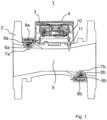
- Reference number 1 in Fig. 1 refers to a fluid meter based on ultrasound technology for measuring the flow rate of fluid, for example water, in a fluid supply network.
- the fluid meter has a so-called connection housing 2, by means of which the fluid meter can be converted into a (in Fig. 1 (not shown) pipeline of the fluid supply network is installed.
- a radio communication device for communication with a remotely positioned data collector (concentrator) can preferably also be accommodated in the electronic module 4.
- connection housing 2 comprises, for example, two wall openings, into each of which an insert 7a, 7b made of sound-permeable material (e.g. plastic) is inserted and sealed to the connection housing 2 by a seal 8a, 8b.
- an ultrasonic transducer 6a, 6b Located on the inner wall of the respective insert 7a, 7b an ultrasonic transducer 6a, 6b in a fixed position for emitting an ultrasonic signal through the wall of the respective insert 7a, 7b obliquely or diagonally into the measuring channel 5 towards the opposite ultrasonic transducer 6b or for receiving an ultrasonic signal emitted by the opposite ultrasonic transducer 6b.
- More than two wall openings can also be provided for more than two opposing ultrasonic transducers.
- the respective inserts 7a, 7b can be closed by associated covers 9a, 9b.
- the ultrasonic transducers 6a, 6b are connected to the electronic module 3 via signal paths.
- the fluid meter according to Fig. 1 If necessary, can also have a temperature sensor 11, which protrudes through a top opening 14 into the interior of the connection housing 2 and is also connected to the electronic module via a signal path.
- the fluid meter shows the respective fluid consumption, i.e. the amount of fluid that has flowed through the fluid meter, via its display 4.
- Fluid meters are usually calibrated and protected from manipulation by means of a seal or the like.
- At least one of the two ultrasonic transducers 6a, 6b is used to detect dynamic noises caused by the operation of the fluid meter 1, to selectively record them, to evaluate them and to generate an operating characteristic specific to the fluid meter. If the fluid meter 1 is installed incorrectly, for example, in that part of a seal protrudes into the flow cross section of the fluid meter 1, this may result in the formation of a turbulence area at high flow rates, which can lead to cavitations, which can be detected as dynamic noise by the ultrasonic transducer. The occurrence of cavitations can lead to the flow-guiding internal geometry of the ultrasonic transducer or the measuring insert changing over time due to material removal on surfaces and/or edges, thereby deteriorating the measuring accuracy.
- Turbulence areas can form here, especially around the inserts 7a, 7b, which lead to significant cavitations. It can also be determined if a fluid meter has accidentally been incorrectly fastened when installed and therefore vibrations occur during operation.
- At least one of the two ultrasonic transducers 6a, 6b can also be used to detect a pressure surge caused in the fluid supply network (for example by construction work or by a malfunction of a throttle point) in order to generate an operating characteristic specific to the fluid meter.
- a corresponding disruptive event can be recognized based on the special signal shape or the special signal pattern.
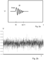
- Fig. 2a shows, for example, a signal shape of an abrupt voltage increase (maximum level Imax at the beginning) at tn and a periodically decaying oscillation with a relatively low frequency lasting over a certain period of time ⁇ t up to tn + 1.
- the signal frequency and / or the signal pattern can be seen the type of fault can be concluded.
- it is e.g. B. a signal form that is due to the occurrence of a briefly increased pressure (e.g. pressure shock due to a suddenly opened valve).
- the method according to the invention can record the exact time, the duration of the disturbance that occurs and/or its intensity.
- tn and tn+1 are the actual time, i.e. the exact time of day when the disruption occurred and the exact time when it ended.
- the signal frequency can also be detected.
- Fig. 2b it is a signal typical of cavitation.
- the signal corresponds to a strong noise with a wide, non-specific frequency spectrum and a compared to Fig. 2a high frequency, e.g. B. due to non-standard, very high flow rates outside the specification of the fluid meter. In the event of such an incident, correct flow determination would no longer be guaranteed or would no longer be possible at all due to the lack of an evaluable signal.
- Fig. 2c it is a curve with individual peaks of different sizes. Such a curve indicates that particles of different sizes (e.g. stones) are flushed through the fluid meter and cause the signal pattern shown by impacting the surface of the insert housing the ultrasonic transducer.
- particles of different sizes e.g. stones
- Periodic oscillations with larger, more or less constant amplitude, cf. Fig. 2d can be due to flow-related vibration due to poor installation (e.g. poor fastening).
- Corresponding (in particular empirically determined) information such as comparison signal shapes, comparison intensities, comparison frequencies and/or comparison periods can be “stored” in the operating system of the fluid meter.
- a “type assignment” of disturbance events can advantageously be carried out based on the measured signals and, as a result, control and/or warning measures can be initiated if necessary.
- the electronics of the operating system can therefore distinguish between simple signal noise, cavitation-specific signal noise, peaks due to pressure shocks and periodic oscillations caused by vibrations.
- Fig. 2e shows, for example, a recurring accident in the form of time-limited recurring cavitations. This results in a curve of two different flow rates alternating, due to the repeatedly occurring cavitations (period of large amplitudes above the standard measuring range) compared to the "normal flow" (period of small amplitudes of the usual noise within the standard measuring range). In the areas of cavitation, it is not possible to measure the transit time difference due to the poor signal quality. The period of small amplitude In contrast, shows the flow within the specification of the fluid meter, at which an exact flow measurement can take place.
- the method according to the invention makes it possible to precisely detect or localize, document and include in the evaluation periods of reduced measurement accuracy.
- the electrical signal generated by the ultrasonic transducer due to a noise is generated solely from the mechanical energy of the noise and without additional energy.
- a fluid meter cf. e.g. b. Fig. 4
- several functional modules are provided, namely in addition to the fluid quantity functional module 16a, an event chronology functional module 16b and, if necessary, the further functional modules overall event history 16c and / or event type 16d.
- the event duration D and/or event intensity I and/or the frequency can be saved and output as information.
- the functional module noise type 16d is concerned, a distinction can be made, for example, between cavity, vibration and/or overpressure (pressure shock).
- the information in question can preferably be viewed on the display 4 of the fluid meter 1 Fig. 1 are displayed.
- warning signals and/or warnings can be displayed on the display if necessary.
- corresponding event data can also be transferred to a data collector (not shown) for management and/or further processing and fed to a central station (also not shown).
- a minimum intensity Imin can be specified as part of the method, by means of which the presence of a signal (S1, S2) following a fault can be distinguished from mere noise or the flow measurement (S3).
- the control and evaluation device in the electronic module of the fluid meter is operated alternately in an active mode and a sleep mode.
- the control and evaluation device is set up in such a way that it only switches the control and evaluation device from sleep mode to active mode based on an electrical signal generated by the ultrasonic transducer due to an extraordinary event of the type mentioned above.
- the present invention makes it possible for the first time to monitor and precisely record the operation of an individual fluid meter with regard to the occurrence of noise and/or vibration-causing malfunctions on the fluid meter over its service life.
- a corresponding incident log is shown in a simplified form as an example Fig. 5 visible.
- a malfunction can be detected in the operating system of the fluid meter, recorded and, if necessary, logged and analyzed accordingly. Additional information (operating characteristics) that is particularly important for the operation of the individual fluid meter can therefore be issued to the user or operator of the fluid meter. As a result, incorrect measurements, incorrect operation, malfunctions and other adverse impairments to the operation of the fluid meter can be quickly detected and remedied.
- the present invention therefore represents a very special contribution to the relevant field of prior art.
Claims (10)
- Procédé de surveillance du fonctionnement d'un compteur de fluide individuel (1) installé dans un réseau de conduites de fluide destiné à l'alimentation en fluide,le compteur de fluide comprenant au moins un transducteur à ultrasons (6a, 6b),le transducteur à ultrasons étant utilisé pour détecter et évaluer sélectivement un événement qui stimule mécaniquement le transducteur à ultrasons, qui n'est pas attribuable à la mesure de débit, qui se présente sous la forme de bruit généré pendant le fonctionnement dans le compteur de fluide et provoqué par le fonctionnement du compteur de fluide et/ou sous la forme d'un coup de bélier provoqué dans le réseau de conduites,au moins une propriété de fonctionnement spécifique au compteur de fluide étant générée sur la base du résultat de cette évaluation etl'événement qui stimule mécaniquement le transducteur à ultrasons étant enregistré pendant le temps t, caractérisé en ce quel'événement est pourvu d'un horodatage,la durée d'événement totale (D) et/ou l'intensité totale (I) des événements détectés sélectivement est/sont enregistrée(s) dans le temps (t), etun historique d'événements spécifique à l'appareil est généré sur la base des événements détectés dans le temps et stimulant mécaniquement le transducteur à ultrasons.
- Procédé selon la revendication 1,
un historique d'événement ou une information d'événement spécifique à l'appareil étant comparé(e) à une caractéristique d'événement et/ou à une grandeur d'événement déterminée(s) de manière empirique et une association de type événement/dommage et/ou une grandeur de commande et/ou de contrôle étant déduite(s) de la comparaison. - Procédé selon la revendication 1 ou 2,
un signal d'avertissement et/ou un message d'avertissement étant généré(s) lorsqu'une durée d'événement (D) et/ou une intensité d'événement (I) spécifiée(s) est/sont dépassée(s). - Procédé selon l'une des revendications précédentes,
l'intensité maximale de l'événement étant détectée et évaluée lorsque celui-ci stimule mécaniquement le transducteur à ultrasons et se présente sous la forme d'un coup de bélier provoqué dans le réseau de conduites. - Procédé selon l'une des revendications précédentes,un dispositif de commande et d'évaluation du compteur de fluide fonctionnant alternativement dans un mode actif et un mode veille etle dispositif de commande et d'évaluation étant conçu de manière à effectuer une commutation du dispositif de commande et d'évaluation du mode veille dans le mode actif uniquement sur la base d'un signal électrique généré par le transducteur à ultrasons à la suite d'un événement.
- Procédé selon l'une des revendications précédentes,
le signal électrique généré par le transducteur à ultrasons à la suite d'un événement étant généré uniquement à partir de l'énergie mécanique de l'événement et sans énergie supplémentaire, le signal électrique étant notamment prévu pour être un motif de signal et/ou un spectre de fréquences et/ou un niveau maximum. - Procédé selon l'une des revendications précédentes,
le transducteur à ultrasons destiné à détecter et évaluer sélectivement l'événement faisant partie d'un ensemble de transducteurs à ultrasons destiné à déterminer le temps de propagation. - Procédé selon l'une des revendications précédentes,l'événement étant dans chaque casun bruit de cavitation provoqué de préférence par le compteur de fluide et/ouun bruit de vibration provoqué de préférence par le compteur de fluide et/ouune sollicitation mécanique du transducteur à ultrasons par des particules situées dans le compteur de fluide ou refoulées à travers celui-ci par lavage.
- Débitmètre (1) destiné à mesurer le débit dans un réseau de conduites de fluide destiné à l'alimentation en fluide, de préférence un réseau de conduites d'eau destiné à l'alimentation en eau, ledit débitmètre comprenantun ensemble de transducteurs à ultrasons destiné à mesurer le temps de propagation, lequel comprend au moins un transducteur à ultrasons, de préférence deux transducteurs à ultrasons (6a, 6b) destiné(s) à émettre des ondes ultrasonores dans le fluide et/ou les recevoir de celui-ci,un module électronique (3) comprenant un dispositif de commande et d'évaluation et un système de fonctionnement (16) destiné à la détection de signal et à l'évaluation de signal des transducteurs à ultrasons (6a, 6b) etune source d'énergie électrique, caractérisé en ce quele système de fonctionnement (16) contient, outre la mesure de débit, un mode de fonctionnement supplémentaire permettant de mettre en œuvre un procédé selon l'une des revendications précédentes.
- Débitmètre selon la revendication 9,
ledit débitmètre disposant d'un boîtier de raccordement (2) qui permet d'installer le débitmètre (1) dans le réseau de conduites de fluide, en particulier un insert de mesure (5) étant prévu pour être disposé à l'intérieur du boîtier de raccordement (2) et comprenant un tube de mesure, des miroirs de déflexion (7a, 7b) destinés au signal ultrasonore et des dispositifs de guidage d'écoulement.
Applications Claiming Priority (2)
| Application Number | Priority Date | Filing Date | Title |
|---|---|---|---|
| DE102017011201.0A DE102017011201B4 (de) | 2017-12-05 | 2017-12-05 | Verfahren zur Betriebsüberwachung eines Fluidzählers sowie Fluidzähler |
| PCT/EP2018/082842 WO2019110387A1 (fr) | 2017-12-05 | 2018-11-28 | Procédé de surveillance du fonctionnement d'un compteur de fluide et compteur de fluide |
Publications (3)
| Publication Number | Publication Date |
|---|---|
| EP3721176A1 EP3721176A1 (fr) | 2020-10-14 |
| EP3721176B1 true EP3721176B1 (fr) | 2023-10-11 |
| EP3721176C0 EP3721176C0 (fr) | 2023-10-11 |
Family
ID=64650359
Family Applications (1)
| Application Number | Title | Priority Date | Filing Date |
|---|---|---|---|
| EP18815126.0A Active EP3721176B1 (fr) | 2017-12-05 | 2018-11-28 | Procédé de surveillance du fonctionnement d'un compteur de fluide et compteur de fluide |
Country Status (5)
| Country | Link |
|---|---|
| US (1) | US11441932B2 (fr) |
| EP (1) | EP3721176B1 (fr) |
| CN (1) | CN111386445B (fr) |
| DE (1) | DE102017011201B4 (fr) |
| WO (1) | WO2019110387A1 (fr) |
Families Citing this family (4)
| Publication number | Priority date | Publication date | Assignee | Title |
|---|---|---|---|---|
| US11215488B2 (en) * | 2019-07-02 | 2022-01-04 | Itron Global Sarl | Transducer enclosure with variable moisture proofing |
| FR3109214B1 (fr) * | 2020-04-09 | 2022-09-02 | Sagemcom Energy & Telecom Sas | Procédé de détection et de localisation d’une fuite de fluide |
| EP4019908B1 (fr) * | 2020-12-28 | 2024-01-17 | Kamstrup A/S | Compteur de consommation de fluide et procédé de détection de son dans un système de conduite |
| DE102021129099A1 (de) | 2021-11-09 | 2023-05-11 | Diehl Metering Gmbh | Druckermittlung mittels piezokeramischem Ultraschall-Wandler |
Citations (1)
| Publication number | Priority date | Publication date | Assignee | Title |
|---|---|---|---|---|
| GB2447691A (en) * | 2007-03-23 | 2008-09-24 | Schlumberger Holdings | Flowmeter using tube waves |
Family Cites Families (14)
| Publication number | Priority date | Publication date | Assignee | Title |
|---|---|---|---|---|
| WO2005010522A2 (fr) * | 2003-07-18 | 2005-02-03 | Rosemount Inc. | Diagnostic de procede |
| US6950768B2 (en) * | 2003-09-08 | 2005-09-27 | Daniel Industries, Inc. | Self-tuning ultrasonic meter |
| DE102008049891B4 (de) * | 2008-10-02 | 2012-12-06 | Hydrometer Gmbh | Strömungsrichter für ein Durchflussmessgerät, insbesondere ein Ultraschallmessgerät |
| EP2686643A4 (fr) * | 2011-03-18 | 2014-09-10 | Soneter Llc | Procédés et appareil pour la mesure d'un écoulement de fluide |
| US9689726B2 (en) * | 2012-07-09 | 2017-06-27 | Texas Instruments Incorporated | Flow meter |
| PL2888561T3 (pl) * | 2012-08-22 | 2021-11-02 | Apator Miitors Aps | Przepływomierz ultradźwiękowy zawierający układ połączeniowy |
| WO2016176521A1 (fr) * | 2015-04-29 | 2016-11-03 | Covidien Lp | Détection de dysfonctionnement d'un système de surveillance d'écoulement d'un appareil de régulation d'écoulement |
| WO2017005268A1 (fr) | 2015-07-03 | 2017-01-12 | Kamstrup A/S | Capteur de turbidité basé sur des mesures ultrasonores |
| EP3112823A1 (fr) | 2015-07-03 | 2017-01-04 | Kamstrup A/S | Système de surveillance d'un réseau utilitaire |
| EP3112820A1 (fr) | 2015-07-03 | 2017-01-04 | Kamstrup A/S | Compteur de consommation de fluide avec capteur de bruit |
| US10527515B2 (en) * | 2016-04-21 | 2020-01-07 | Neptune Technology Group Inc. | Ultrasonic flow meter leak detection system and method |
| US11353347B2 (en) * | 2017-03-22 | 2022-06-07 | Texas Instruments Incorporated | Ultrasonic flow meter and excitation method |
| US10295387B2 (en) * | 2017-04-25 | 2019-05-21 | Vittorio BONOMI | Integrated ball valve and ultrasonic flowmeter |
| US20200240820A1 (en) * | 2019-01-30 | 2020-07-30 | Intellecy, Inc. | Systems and methods for fluid flow detection |
-
2017
- 2017-12-05 DE DE102017011201.0A patent/DE102017011201B4/de active Active
-
2018
- 2018-11-28 WO PCT/EP2018/082842 patent/WO2019110387A1/fr unknown
- 2018-11-28 CN CN201880076200.1A patent/CN111386445B/zh active Active
- 2018-11-28 EP EP18815126.0A patent/EP3721176B1/fr active Active
-
2020
- 2020-06-05 US US16/893,668 patent/US11441932B2/en active Active
Patent Citations (1)
| Publication number | Priority date | Publication date | Assignee | Title |
|---|---|---|---|---|
| GB2447691A (en) * | 2007-03-23 | 2008-09-24 | Schlumberger Holdings | Flowmeter using tube waves |
Also Published As
| Publication number | Publication date |
|---|---|
| US11441932B2 (en) | 2022-09-13 |
| CN111386445B (zh) | 2023-12-08 |
| EP3721176C0 (fr) | 2023-10-11 |
| DE102017011201B4 (de) | 2023-01-26 |
| US20200300679A1 (en) | 2020-09-24 |
| EP3721176A1 (fr) | 2020-10-14 |
| CN111386445A (zh) | 2020-07-07 |
| DE102017011201A1 (de) | 2019-06-06 |
| WO2019110387A1 (fr) | 2019-06-13 |
Similar Documents
| Publication | Publication Date | Title |
|---|---|---|
| EP3721176B1 (fr) | Procédé de surveillance du fonctionnement d'un compteur de fluide et compteur de fluide | |
| EP1216375B2 (fr) | Systeme et procede de diagnostic, notamment pour soupape | |
| EP3428583B1 (fr) | Procédé de fonctionnement d'un compteur de fluide et compteur de fluide | |
| EP2406586B1 (fr) | Appareil de mesure d'écoulement tourbillonnaire, destiné à surveiller et/ou mesurer un écoulement distribué de particules et/ou de gouttelettes | |
| EP2191182B1 (fr) | Système diagnostique et procédé de diagnostic pour une soupape, en particulier une soupape de fermeture ou une soupape de réglage | |
| EP1499825B1 (fr) | Systeme et procede de diagnostique pour une vanne | |
| DE102007013176B4 (de) | Durchflussratenmessvorrichtung | |
| EP2406585B1 (fr) | Procédé et appareil de mesure d'écoulement tourbillonnaire, destinés à surveiller et/ou mesurer un écoulement pariétal d'un fluide traversant une conduite tubulaire et possédant deux phases ou plus | |
| EP1993742B1 (fr) | Dispositif pour déterminer et/ou surveiller le débit volumique ou massique d'une substance dans une conduite tubulaire | |
| DE102004053142B4 (de) | Flanschwirbeldurchflußmesser mit unitären zulaufenden Erweiterungsstücken | |
| EP3234512B1 (fr) | Débitmètre à pression différentielle | |
| DE102012220505B4 (de) | Überwachung eines Kondensatableiters | |
| EP3922972A2 (fr) | Dispositif de mesure de la pression d'un fluide circulant dans une tuyauterie | |
| DE102015001379B4 (de) | Durchflusszähler | |
| EP1573276B1 (fr) | Dispositif de positionnement d'un appareil de mesure de debit sous forme de pince de serrage sur un contenant | |
| EP1096237A2 (fr) | Débitmètre ultrasonique | |
| DE19517289A1 (de) | Überwachungssystem zur Feststellung einer Kavitationsintensität | |
| EP0887626A1 (fr) | Ensembles de substitution pour débitmètres de volume et débitmètres à tourbillon correspondants | |
| DE102011016963A1 (de) | Verfahren zur Messung von Durchflussmengen nach dem Prinzip der Ultraschalllaufzeitdifferenz | |
| DE102021129096A1 (de) | Verfahren zum Betrieb eines Ultraschall-Fluidzählers sowie Ultraschall-Fluidzähler | |
| DE102021117707A1 (de) | Meßsystem zum Messen eines Strömungsparameters eines in einer Rohrleitung strömenden fluiden Meßstoffs | |
| DE102015210732A1 (de) | Vorrichtung zur Halterung von Schallwandlern sowie Ultraschalldurchflussmessgerät | |
| EP1731883A1 (fr) | Procédé pour détecter un changement géométrique d'un canal de mesure de débit par ultrasons | |
| EP3971535A1 (fr) | Convertisseur à ultrasons, débitmètre à ultrasons et procédé | |
| WO2010091700A1 (fr) | Procédé pour faire fonctionner un débitmètre massique à effet coriolis et débitmètre massique à effet coriolis |
Legal Events
| Date | Code | Title | Description |
|---|---|---|---|
| STAA | Information on the status of an ep patent application or granted ep patent |
Free format text: STATUS: UNKNOWN |
|
| STAA | Information on the status of an ep patent application or granted ep patent |
Free format text: STATUS: THE INTERNATIONAL PUBLICATION HAS BEEN MADE |
|
| PUAI | Public reference made under article 153(3) epc to a published international application that has entered the european phase |
Free format text: ORIGINAL CODE: 0009012 |
|
| STAA | Information on the status of an ep patent application or granted ep patent |
Free format text: STATUS: REQUEST FOR EXAMINATION WAS MADE |
|
| 17P | Request for examination filed |
Effective date: 20200528 |
|
| AK | Designated contracting states |
Kind code of ref document: A1 Designated state(s): AL AT BE BG CH CY CZ DE DK EE ES FI FR GB GR HR HU IE IS IT LI LT LU LV MC MK MT NL NO PL PT RO RS SE SI SK SM TR |
|
| AX | Request for extension of the european patent |
Extension state: BA ME |
|
| DAV | Request for validation of the european patent (deleted) | ||
| DAX | Request for extension of the european patent (deleted) | ||
| STAA | Information on the status of an ep patent application or granted ep patent |
Free format text: STATUS: EXAMINATION IS IN PROGRESS |
|
| 17Q | First examination report despatched |
Effective date: 20221114 |
|
| REG | Reference to a national code |
Ref country code: DE Ref legal event code: R079 Ref document number: 502018013455 Country of ref document: DE Free format text: PREVIOUS MAIN CLASS: G01F0001660000 Ipc: G01F0025100000 Ref country code: DE Ref legal event code: R079 Free format text: PREVIOUS MAIN CLASS: G01F0001660000 Ipc: G01F0025100000 |
|
| RIC1 | Information provided on ipc code assigned before grant |
Ipc: G01F 1/66 20060101ALI20230327BHEP Ipc: G01F 15/18 20060101ALI20230327BHEP Ipc: G01F 25/10 20220101AFI20230327BHEP |
|
| GRAP | Despatch of communication of intention to grant a patent |
Free format text: ORIGINAL CODE: EPIDOSNIGR1 |
|
| STAA | Information on the status of an ep patent application or granted ep patent |
Free format text: STATUS: GRANT OF PATENT IS INTENDED |
|
| INTG | Intention to grant announced |
Effective date: 20230601 |
|
| GRAS | Grant fee paid |
Free format text: ORIGINAL CODE: EPIDOSNIGR3 |
|
| GRAA | (expected) grant |
Free format text: ORIGINAL CODE: 0009210 |
|
| STAA | Information on the status of an ep patent application or granted ep patent |
Free format text: STATUS: THE PATENT HAS BEEN GRANTED |
|
| AK | Designated contracting states |
Kind code of ref document: B1 Designated state(s): AL AT BE BG CH CY CZ DE DK EE ES FI FR GB GR HR HU IE IS IT LI LT LU LV MC MK MT NL NO PL PT RO RS SE SI SK SM TR |
|
| REG | Reference to a national code |
Ref country code: GB Ref legal event code: FG4D Free format text: NOT ENGLISH |
|
| REG | Reference to a national code |
Ref country code: CH Ref legal event code: EP |
|
| REG | Reference to a national code |
Ref country code: DE Ref legal event code: R096 Ref document number: 502018013455 Country of ref document: DE |
|
| REG | Reference to a national code |
Ref country code: IE Ref legal event code: FG4D Free format text: LANGUAGE OF EP DOCUMENT: GERMAN |
|
| U01 | Request for unitary effect filed |
Effective date: 20231030 |
|
| U07 | Unitary effect registered |
Designated state(s): AT BE BG DE DK EE FI FR IT LT LU LV MT NL PT SE SI Effective date: 20231103 |
|
| U20 | Renewal fee paid [unitary effect] |
Year of fee payment: 6 Effective date: 20231113 |
|
| PGFP | Annual fee paid to national office [announced via postgrant information from national office to epo] |
Ref country code: GB Payment date: 20231123 Year of fee payment: 6 |
|
| PG25 | Lapsed in a contracting state [announced via postgrant information from national office to epo] |
Ref country code: GR Free format text: LAPSE BECAUSE OF FAILURE TO SUBMIT A TRANSLATION OF THE DESCRIPTION OR TO PAY THE FEE WITHIN THE PRESCRIBED TIME-LIMIT Effective date: 20240112 |
|
| PG25 | Lapsed in a contracting state [announced via postgrant information from national office to epo] |
Ref country code: IS Free format text: LAPSE BECAUSE OF FAILURE TO SUBMIT A TRANSLATION OF THE DESCRIPTION OR TO PAY THE FEE WITHIN THE PRESCRIBED TIME-LIMIT Effective date: 20240211 |
|
| PG25 | Lapsed in a contracting state [announced via postgrant information from national office to epo] |
Ref country code: ES Free format text: LAPSE BECAUSE OF FAILURE TO SUBMIT A TRANSLATION OF THE DESCRIPTION OR TO PAY THE FEE WITHIN THE PRESCRIBED TIME-LIMIT Effective date: 20231011 |
|
| PG25 | Lapsed in a contracting state [announced via postgrant information from national office to epo] |
Ref country code: IS Free format text: LAPSE BECAUSE OF FAILURE TO SUBMIT A TRANSLATION OF THE DESCRIPTION OR TO PAY THE FEE WITHIN THE PRESCRIBED TIME-LIMIT Effective date: 20240211 Ref country code: GR Free format text: LAPSE BECAUSE OF FAILURE TO SUBMIT A TRANSLATION OF THE DESCRIPTION OR TO PAY THE FEE WITHIN THE PRESCRIBED TIME-LIMIT Effective date: 20240112 Ref country code: ES Free format text: LAPSE BECAUSE OF FAILURE TO SUBMIT A TRANSLATION OF THE DESCRIPTION OR TO PAY THE FEE WITHIN THE PRESCRIBED TIME-LIMIT Effective date: 20231011 |