EP3720732B1 - Système de réfrigérant pour véhicule - Google Patents
Système de réfrigérant pour véhicule Download PDFInfo
- Publication number
- EP3720732B1 EP3720732B1 EP17816620.3A EP17816620A EP3720732B1 EP 3720732 B1 EP3720732 B1 EP 3720732B1 EP 17816620 A EP17816620 A EP 17816620A EP 3720732 B1 EP3720732 B1 EP 3720732B1
- Authority
- EP
- European Patent Office
- Prior art keywords
- coolant
- cooler
- heat generating
- vehicle
- temperature
- Prior art date
- Legal status (The legal status is an assumption and is not a legal conclusion. Google has not performed a legal analysis and makes no representation as to the accuracy of the status listed.)
- Active
Links
- 239000002826 coolant Substances 0.000 title claims description 314
- 239000012530 fluid Substances 0.000 claims description 120
- 238000004891 communication Methods 0.000 claims description 66
- 238000011144 upstream manufacturing Methods 0.000 claims description 14
- 238000010438 heat treatment Methods 0.000 claims description 5
- 230000000630 rising effect Effects 0.000 claims description 4
- 238000001816 cooling Methods 0.000 description 24
- 239000003570 air Substances 0.000 description 14
- 239000007788 liquid Substances 0.000 description 9
- XLYOFNOQVPJJNP-UHFFFAOYSA-N water Substances O XLYOFNOQVPJJNP-UHFFFAOYSA-N 0.000 description 5
- 239000012080 ambient air Substances 0.000 description 4
- 230000008901 benefit Effects 0.000 description 4
- LYCAIKOWRPUZTN-UHFFFAOYSA-N Ethylene glycol Chemical compound OCCO LYCAIKOWRPUZTN-UHFFFAOYSA-N 0.000 description 3
- 238000002485 combustion reaction Methods 0.000 description 3
- 238000010276 construction Methods 0.000 description 3
- 230000000694 effects Effects 0.000 description 3
- 238000009434 installation Methods 0.000 description 3
- QGZKDVFQNNGYKY-UHFFFAOYSA-N Ammonia Chemical compound N QGZKDVFQNNGYKY-UHFFFAOYSA-N 0.000 description 2
- 230000003247 decreasing effect Effects 0.000 description 2
- 238000009439 industrial construction Methods 0.000 description 2
- 239000000654 additive Substances 0.000 description 1
- 238000004378 air conditioning Methods 0.000 description 1
- 229910021529 ammonia Inorganic materials 0.000 description 1
- 230000002457 bidirectional effect Effects 0.000 description 1
- 230000005540 biological transmission Effects 0.000 description 1
- 239000000110 cooling liquid Substances 0.000 description 1
- 230000007797 corrosion Effects 0.000 description 1
- 238000005260 corrosion Methods 0.000 description 1
- 230000001419 dependent effect Effects 0.000 description 1
- 230000007613 environmental effect Effects 0.000 description 1
- 230000003628 erosive effect Effects 0.000 description 1
- 238000007710 freezing Methods 0.000 description 1
- 230000008014 freezing Effects 0.000 description 1
- 150000002334 glycols Chemical class 0.000 description 1
- 239000000203 mixture Substances 0.000 description 1
- 238000012986 modification Methods 0.000 description 1
- 230000004048 modification Effects 0.000 description 1
Images

Classifications
-
- B—PERFORMING OPERATIONS; TRANSPORTING
- B60—VEHICLES IN GENERAL
- B60K—ARRANGEMENT OR MOUNTING OF PROPULSION UNITS OR OF TRANSMISSIONS IN VEHICLES; ARRANGEMENT OR MOUNTING OF PLURAL DIVERSE PRIME-MOVERS IN VEHICLES; AUXILIARY DRIVES FOR VEHICLES; INSTRUMENTATION OR DASHBOARDS FOR VEHICLES; ARRANGEMENTS IN CONNECTION WITH COOLING, AIR INTAKE, GAS EXHAUST OR FUEL SUPPLY OF PROPULSION UNITS IN VEHICLES
- B60K1/00—Arrangement or mounting of electrical propulsion units
-
- B—PERFORMING OPERATIONS; TRANSPORTING
- B60—VEHICLES IN GENERAL
- B60L—PROPULSION OF ELECTRICALLY-PROPELLED VEHICLES; SUPPLYING ELECTRIC POWER FOR AUXILIARY EQUIPMENT OF ELECTRICALLY-PROPELLED VEHICLES; ELECTRODYNAMIC BRAKE SYSTEMS FOR VEHICLES IN GENERAL; MAGNETIC SUSPENSION OR LEVITATION FOR VEHICLES; MONITORING OPERATING VARIABLES OF ELECTRICALLY-PROPELLED VEHICLES; ELECTRIC SAFETY DEVICES FOR ELECTRICALLY-PROPELLED VEHICLES
- B60L58/00—Methods or circuit arrangements for monitoring or controlling batteries or fuel cells, specially adapted for electric vehicles
- B60L58/10—Methods or circuit arrangements for monitoring or controlling batteries or fuel cells, specially adapted for electric vehicles for monitoring or controlling batteries
- B60L58/24—Methods or circuit arrangements for monitoring or controlling batteries or fuel cells, specially adapted for electric vehicles for monitoring or controlling batteries for controlling the temperature of batteries
- B60L58/26—Methods or circuit arrangements for monitoring or controlling batteries or fuel cells, specially adapted for electric vehicles for monitoring or controlling batteries for controlling the temperature of batteries by cooling
-
- B—PERFORMING OPERATIONS; TRANSPORTING
- B60—VEHICLES IN GENERAL
- B60L—PROPULSION OF ELECTRICALLY-PROPELLED VEHICLES; SUPPLYING ELECTRIC POWER FOR AUXILIARY EQUIPMENT OF ELECTRICALLY-PROPELLED VEHICLES; ELECTRODYNAMIC BRAKE SYSTEMS FOR VEHICLES IN GENERAL; MAGNETIC SUSPENSION OR LEVITATION FOR VEHICLES; MONITORING OPERATING VARIABLES OF ELECTRICALLY-PROPELLED VEHICLES; ELECTRIC SAFETY DEVICES FOR ELECTRICALLY-PROPELLED VEHICLES
- B60L1/00—Supplying electric power to auxiliary equipment of vehicles
- B60L1/02—Supplying electric power to auxiliary equipment of vehicles to electric heating circuits
-
- B—PERFORMING OPERATIONS; TRANSPORTING
- B60—VEHICLES IN GENERAL
- B60L—PROPULSION OF ELECTRICALLY-PROPELLED VEHICLES; SUPPLYING ELECTRIC POWER FOR AUXILIARY EQUIPMENT OF ELECTRICALLY-PROPELLED VEHICLES; ELECTRODYNAMIC BRAKE SYSTEMS FOR VEHICLES IN GENERAL; MAGNETIC SUSPENSION OR LEVITATION FOR VEHICLES; MONITORING OPERATING VARIABLES OF ELECTRICALLY-PROPELLED VEHICLES; ELECTRIC SAFETY DEVICES FOR ELECTRICALLY-PROPELLED VEHICLES
- B60L58/00—Methods or circuit arrangements for monitoring or controlling batteries or fuel cells, specially adapted for electric vehicles
- B60L58/10—Methods or circuit arrangements for monitoring or controlling batteries or fuel cells, specially adapted for electric vehicles for monitoring or controlling batteries
- B60L58/24—Methods or circuit arrangements for monitoring or controlling batteries or fuel cells, specially adapted for electric vehicles for monitoring or controlling batteries for controlling the temperature of batteries
- B60L58/27—Methods or circuit arrangements for monitoring or controlling batteries or fuel cells, specially adapted for electric vehicles for monitoring or controlling batteries for controlling the temperature of batteries by heating
-
- H—ELECTRICITY
- H01—ELECTRIC ELEMENTS
- H01M—PROCESSES OR MEANS, e.g. BATTERIES, FOR THE DIRECT CONVERSION OF CHEMICAL ENERGY INTO ELECTRICAL ENERGY
- H01M10/00—Secondary cells; Manufacture thereof
- H01M10/60—Heating or cooling; Temperature control
- H01M10/61—Types of temperature control
- H01M10/613—Cooling or keeping cold
-
- H—ELECTRICITY
- H01—ELECTRIC ELEMENTS
- H01M—PROCESSES OR MEANS, e.g. BATTERIES, FOR THE DIRECT CONVERSION OF CHEMICAL ENERGY INTO ELECTRICAL ENERGY
- H01M10/00—Secondary cells; Manufacture thereof
- H01M10/60—Heating or cooling; Temperature control
- H01M10/62—Heating or cooling; Temperature control specially adapted for specific applications
- H01M10/625—Vehicles
-
- H—ELECTRICITY
- H01—ELECTRIC ELEMENTS
- H01M—PROCESSES OR MEANS, e.g. BATTERIES, FOR THE DIRECT CONVERSION OF CHEMICAL ENERGY INTO ELECTRICAL ENERGY
- H01M10/00—Secondary cells; Manufacture thereof
- H01M10/60—Heating or cooling; Temperature control
- H01M10/65—Means for temperature control structurally associated with the cells
- H01M10/655—Solid structures for heat exchange or heat conduction
- H01M10/6556—Solid parts with flow channel passages or pipes for heat exchange
-
- B—PERFORMING OPERATIONS; TRANSPORTING
- B60—VEHICLES IN GENERAL
- B60K—ARRANGEMENT OR MOUNTING OF PROPULSION UNITS OR OF TRANSMISSIONS IN VEHICLES; ARRANGEMENT OR MOUNTING OF PLURAL DIVERSE PRIME-MOVERS IN VEHICLES; AUXILIARY DRIVES FOR VEHICLES; INSTRUMENTATION OR DASHBOARDS FOR VEHICLES; ARRANGEMENTS IN CONNECTION WITH COOLING, AIR INTAKE, GAS EXHAUST OR FUEL SUPPLY OF PROPULSION UNITS IN VEHICLES
- B60K1/00—Arrangement or mounting of electrical propulsion units
- B60K2001/003—Arrangement or mounting of electrical propulsion units with means for cooling the electrical propulsion units
- B60K2001/005—Arrangement or mounting of electrical propulsion units with means for cooling the electrical propulsion units the electric storage means
-
- B—PERFORMING OPERATIONS; TRANSPORTING
- B60—VEHICLES IN GENERAL
- B60K—ARRANGEMENT OR MOUNTING OF PROPULSION UNITS OR OF TRANSMISSIONS IN VEHICLES; ARRANGEMENT OR MOUNTING OF PLURAL DIVERSE PRIME-MOVERS IN VEHICLES; AUXILIARY DRIVES FOR VEHICLES; INSTRUMENTATION OR DASHBOARDS FOR VEHICLES; ARRANGEMENTS IN CONNECTION WITH COOLING, AIR INTAKE, GAS EXHAUST OR FUEL SUPPLY OF PROPULSION UNITS IN VEHICLES
- B60K1/00—Arrangement or mounting of electrical propulsion units
- B60K2001/008—Arrangement or mounting of electrical propulsion units with means for heating the electrical propulsion units
-
- B—PERFORMING OPERATIONS; TRANSPORTING
- B60—VEHICLES IN GENERAL
- B60L—PROPULSION OF ELECTRICALLY-PROPELLED VEHICLES; SUPPLYING ELECTRIC POWER FOR AUXILIARY EQUIPMENT OF ELECTRICALLY-PROPELLED VEHICLES; ELECTRODYNAMIC BRAKE SYSTEMS FOR VEHICLES IN GENERAL; MAGNETIC SUSPENSION OR LEVITATION FOR VEHICLES; MONITORING OPERATING VARIABLES OF ELECTRICALLY-PROPELLED VEHICLES; ELECTRIC SAFETY DEVICES FOR ELECTRICALLY-PROPELLED VEHICLES
- B60L2200/00—Type of vehicles
- B60L2200/40—Working vehicles
-
- B—PERFORMING OPERATIONS; TRANSPORTING
- B60—VEHICLES IN GENERAL
- B60L—PROPULSION OF ELECTRICALLY-PROPELLED VEHICLES; SUPPLYING ELECTRIC POWER FOR AUXILIARY EQUIPMENT OF ELECTRICALLY-PROPELLED VEHICLES; ELECTRODYNAMIC BRAKE SYSTEMS FOR VEHICLES IN GENERAL; MAGNETIC SUSPENSION OR LEVITATION FOR VEHICLES; MONITORING OPERATING VARIABLES OF ELECTRICALLY-PROPELLED VEHICLES; ELECTRIC SAFETY DEVICES FOR ELECTRICALLY-PROPELLED VEHICLES
- B60L2240/00—Control parameters of input or output; Target parameters
- B60L2240/10—Vehicle control parameters
- B60L2240/36—Temperature of vehicle components or parts
-
- B—PERFORMING OPERATIONS; TRANSPORTING
- B60—VEHICLES IN GENERAL
- B60L—PROPULSION OF ELECTRICALLY-PROPELLED VEHICLES; SUPPLYING ELECTRIC POWER FOR AUXILIARY EQUIPMENT OF ELECTRICALLY-PROPELLED VEHICLES; ELECTRODYNAMIC BRAKE SYSTEMS FOR VEHICLES IN GENERAL; MAGNETIC SUSPENSION OR LEVITATION FOR VEHICLES; MONITORING OPERATING VARIABLES OF ELECTRICALLY-PROPELLED VEHICLES; ELECTRIC SAFETY DEVICES FOR ELECTRICALLY-PROPELLED VEHICLES
- B60L2240/00—Control parameters of input or output; Target parameters
- B60L2240/40—Drive Train control parameters
- B60L2240/54—Drive Train control parameters related to batteries
- B60L2240/545—Temperature
-
- H—ELECTRICITY
- H01—ELECTRIC ELEMENTS
- H01M—PROCESSES OR MEANS, e.g. BATTERIES, FOR THE DIRECT CONVERSION OF CHEMICAL ENERGY INTO ELECTRICAL ENERGY
- H01M2220/00—Batteries for particular applications
- H01M2220/20—Batteries in motive systems, e.g. vehicle, ship, plane
-
- Y—GENERAL TAGGING OF NEW TECHNOLOGICAL DEVELOPMENTS; GENERAL TAGGING OF CROSS-SECTIONAL TECHNOLOGIES SPANNING OVER SEVERAL SECTIONS OF THE IPC; TECHNICAL SUBJECTS COVERED BY FORMER USPC CROSS-REFERENCE ART COLLECTIONS [XRACs] AND DIGESTS
- Y02—TECHNOLOGIES OR APPLICATIONS FOR MITIGATION OR ADAPTATION AGAINST CLIMATE CHANGE
- Y02T—CLIMATE CHANGE MITIGATION TECHNOLOGIES RELATED TO TRANSPORTATION
- Y02T90/00—Enabling technologies or technologies with a potential or indirect contribution to GHG emissions mitigation
- Y02T90/10—Technologies relating to charging of electric vehicles
- Y02T90/16—Information or communication technologies improving the operation of electric vehicles
Definitions
- the invention relates to a coolant system for a vehicle, in particular an electric vehicle, e.g. an electric working machine.
- the invention also relates to a vehicle comprising such a coolant system, e.g. an electric working machine comprising such a coolant system.
- the invention is applicable on working machines within the fields of industrial construction machines or construction equipment, in particular electric-powered working machines.
- the invention will be described with respect to an autonomous electric working machine, the invention is not restricted to this particular machine, but may also be used in other working machines such as electric wheel loaders, electric articulated haulers, electric excavators, electric backhoe loaders, and also in other types of electric vehicles such as electric busses, electric trucks, electric cars etc. Additionally, the invention may be used in other vehicles such as hybrid vehicles and vehicles having an internal combustion engine etc.
- the energy flowing into the battery pack as it is charged or discharged to power the vehicle and its accessories causes heating in the battery cells and their interconnection systems, i.e. other heat generating components in the vehicle.
- a too high temperature of the battery pack may lower its performance and shorten its lifetime.
- coolant systems which are designed to manage various types of cooling desired for a vehicle, as for example in US 8,215,432
- a coolant system based on fluid which is designed for the cooling of various types of heat generating components in an electric vehicle, such as an electric working machine, in order to optimize the cooling and at least maintain the operational performance of the vehicle.
- Document WO2014/044481 describes a coolant circuit for vehicles, having at least a first component that emits heat in a low temperature range and at least a second component that emits heat in a higher temperature range.
- the at least one second component is arranged downstream of the first component, viewed in the flow direction of the coolant.
- the cooling liquid is cooled in a first heat exchanger, part of the liquid cooling the second component, the other part of the liquid passing through a second heat exchanger before cooling the first component.
- An object of the invention is to provide a coolant system for a vehicle, such as an electric vehicle, e.g. an electric working machine, which system aims at increasing the performance of the system, in particular in terms of improved control of providing efficient cooling of various types of vehicle heat generating components.
- the object is at least partly achieved by a coolant system according to claim 1.
- a coolant system for an electric vehicle the vehicle comprises at least a first vehicle heat generating component and a second vehicle heat generating component.
- the coolant system comprises a fluid circuit configured to define a fluid passageway for circulating a coolant there through and a coolant assembly arranged in the fluid circuit.
- the coolant assembly is configured to decrease the temperature of a portion of the coolant to a first temperature and to supply the portion of coolant to the first vehicle heat generating component via a first supply branch of the fluid circuit. Further, the coolant assembly is configured to decrease the temperature of a remaining portion of the coolant to a second temperature and to supply the remaining portion of coolant to the second heat generating component via a second supply branch of the fluid circuit.
- the system further comprises a first pump unit arranged downstream of the coolant assembly in the first supply branch and in fluid communication with the coolant assembly and the first vehicle heat generating component.
- the first pump unit is configured to direct the portion of coolant to the first vehicle heat generating component.
- the system comprises a second pump.
- the second pump unit is arranged downstream of the coolant assembly in the second supply branch and in fluid communication with the coolant assembly and the second vehicle heat generating component.
- the second pump unit is configured to direct the remaining portion of coolant to the second vehicle heat generating component.
- the example embodiments of the coolant system are intended for cooling various types of power electronics.
- the system as mentioned above is particularly useful when the second vehicle heat generating component is a battery pack.
- the example embodiments provide an improved coolant system for vehicle heat generating components requiring different cooling temperatures, e.g. batteries typically require lower temperatures than other heat generating components.
- the coolant assembly which is in fluid communication with the first supply branch and the second supply branch, is configured to provide a first portion of coolant and a second portion of coolant having different temperatures.
- the arrangement according to the example embodiments allows the coolant to be used in the first and second supply branches to have different temperatures since there is an additional cooling of the coolant used in the second supply branch by the coolant assembly before the coolant enters the second pump unit.
- the example embodiments are particularly useful for an electric-powered automated hauler, which is a full electric machine.
- all high voltage components require cooling, e.g. inverters, electric motors and battery packs.
- the battery pack is particular sensitive and requires a lower temperature than other components.
- the second temperature is typically a lower temperature than the first temperature.
- the second vehicle heat generating component is thus a battery pack.
- the first vehicle heat generating component may be any one of an inverter, an electric motor, DC/DC converter, on-board charger or any other electric component.
- the first vehicle heat generating component may be a hydraulic component or the like, or any other conceivable component generating heat.
- the first and second pump units in the system are intended for directing and circulating the coolant in the closed circuit.
- the circulating coolant absorbs heat from the vehicle heat generating components, e.g. the battery pack, and releases heat via the coolant assembly.
- the fluid circuit is formed by the first supply branch, the second supply branch and a return flow path.
- the first supply branch and the second supply branch intersects into the return flow path.
- the fluid circuit may in some example embodiments comprise additional fluid passages, supply branches or the like depending on the configuration of the system, the design of the coolant assembly and the number of components, e.g. the number of vehicle heat generating components.
- the coolant assembly is configured to decrease the temperature of a first portion of the coolant to the first temperature in a first cooler and to supply the portion of coolant to the first vehicle heat generating component via the first supply branch and further configured to decrease the temperature of a remaining second portion of the coolant to the second temperature in a second cooler and to supply the remaining portion of coolant to the battery pack via the second supply branch.
- the coolant assembly may not strictly necessarily comprise two separate coolers. Rather, the coolant assembly may be configured to decrease the temperature of the portion of the coolant to the first temperature in a first stage at a first part of the coolant assembly, and to decrease the temperature of the remaining portion of the coolant to the second temperature in a following stage at a second part of the coolant assembly.
- the coolant assembly is configured to decrease the temperature of the portion of the coolant to the first temperature in the first stage at the first part of the coolant assembly, and to decrease the temperature of the remaining portion of the coolant to the second temperature in the following stage at the second part of the coolant assembly.
- the first and second parts of the coolant assembly are in fluid communication with each other.
- the coolant assembly comprises the first cooler configured to supply the portion of the coolant at the first temperature to the first vehicle heat generating component and the second cooler configured to supply the remaining potion of the coolant at the second temperature to the second vehicle heat generating component (i.e. the battery pack), wherein the first cooler and the second cooler are separate components arranged in series in the fluid circuit.
- the first cooler and the second cooler are separate components arranged in series in the fluid circuit.
- the first cooler has an inlet in fluid communication with the first and second vehicle heat generating components and an outlet in fluid communication with the second cooler and the first pump unit.
- the second cooler has an inlet in fluid communication with the first cooler and an outlet in fluid communication with the second pump unit.
- the system further comprises a controllable valve for directing the flow of coolant and a heater for heating the coolant, the controllable valve being arranged upstream of the coolant assembly in a return flow path of the fluid circuit.
- the first supply branch and the second supply branch intersect into the return flow path upstream of the controllable valve.
- the controllable valve is in fluid communication with the coolant assembly and the heater.
- the heater is arranged in a by-pass branch extending from the controllable valve.
- the heater is also in fluid communication with the controllable valve and any one of second vehicle heat generating component (e.g. the battery pack) and the first vehicle heat generating component, so that the controllable valve can control the flow of coolant to the coolant assembly and the heater.
- controllable valve is a non-return valve, check valve or the like.
- valve may be any one of a pneumatic valve, an electro-magnetic valve, an electro-pneumatic valve or the like.
- the coolant system may comprise an expansion device having an inner volume to allow the coolant to expand with rising temperature and pressure.
- the system further comprises a control unit adapted to control the coolant assembly.
- the control unit is adapted to set the level of the first and second temperatures.
- the control unit may include a microprocessor, microcontroller, programmable digital signal processor or another programmable device.
- the control unit may also, or instead, include an application specific integrated circuit, a programmable gate array or programmable array logic, a programmable logic device, or a digital signal processor.
- the control unit includes a programmable device such as the microprocessor, microcontroller or programmable digital signal processor mentioned above, the processor may further include computer executable code that controls operation of the programmable device.
- the coolant assembly is typically arranged in connection with one or several types of fans, adapted to direct air towards the coolant assembly.
- the coolant assembly is typically arranged to receive a flow of ambient air.
- the ambient air flow is being blown by one or several fan(s).
- the air flow may arise from the wind speed when driving the vehicle in a forward direction.
- the system is provided without a fan, i.e. no fan is used, which means that only wind speed or the environmental temperature difference is used to cool off the coolant assembly.
- the first and second coolers may for example be located adjacent to each other such that they may benefit from the same air stream and using the same fan.
- an electric vehicle thermal management system which comprises a coolant system according to any one of the example embodiments and/or the features as described above in relation to the first aspect of the present invention.
- the electric vehicle thermal management system comprises at least a battery pack and a vehicle heat generating component in fluid communication with the coolant assembly.
- a vehicle preferably an electric vehicle, which comprises a coolant system according to any one of the example embodiments and/or the features as described above in relation to the first aspect of the present invention and/or an electric vehicle thermal management system according to any one of the example embodiments and/or the features as described above in relation to the second aspect of the present invention.
- a vehicle in the form of a working machine, in particular an electric-powered automated hauler.
- the electric-powered automated hauler is a full electric machine.
- all high voltage components require cooling, e.g. inverters, electric motors and battery packs.
- the battery pack is particular sensitive and requires a lower temperature than other components.
- the electric vehicle comprises a coolant system 100 according to any one of the example embodiments described hereinafter in relation to the Figs. 2 - 3 .
- the vehicle can be of a variety of alternative types, e.g.
- the vehicle may be a bus, car, truck or another type of working machine such as a wheel loader, hauler or the like.
- the vehicle may be an electric vehicle, e.g. an electric bus, car, truck or another type of electric working machine such as a wheel loader, hauler or the like.
- the coolant system 100 in Figs. 1a - 1b and further components of the system are described in more detail below with reference to Figs. 2 - 3 .
- a working machine 1 is described.
- the example embodiment of the coolant system is applicable on any working machines within the fields of industrial construction machines or construction equipment, in particular dumpers/haulers.
- the invention will be described with respect to a hauler, the invention is not restricted to this particular machine, but may also be used in other working machines such as articulated haulers, excavators, backhoe loaders and wheel loaders.
- the working machine comprises a dump body 030 for accommodating a load.
- the dump body 130 may be a loading platform of the working machine 1.
- the working machine 1 is adapted to have a load receiving condition in which the dump body 130 comprises an open load receiving area 131 outwardly delimited by a load receiving area circumference 134.
- Fig. 1a an embodiment is shown where the working machine 1 is adapted to assume the load receiving condition in a normal state.
- the working machine 1 embodiment illustrated in Fig. 1a comprises the dump body 130 which comprises an open load receiving area 131 outwardly delimited by a load receiving area circumference 134.
- cover means not shown, such as a lid, that is adapted to cover at least a portion of the dump body 130.
- the working machine in this example has no driver seat, but is intended to be autonomously and/or remotely driven.
- the working machine 1 further comprises a load dumping side 12 and an opposite side which herein referred to as the opposite side 13.
- the opposite side 13 may be used as a front end side when the machine is driven in the direction that puts the opposite side 13 first.
- the working machine 1 may be drivable in any direction, i.e. it is bidirectional.
- the dump body 130 comprise a load dumping end portion 132 arranged on the working machines load dumping side 12, and an opposite end portion 133 arranged on the working machines opposite side 13.
- the working machine 1 comprise a working machine frame 120 to which a pair of propulsion axles 110 are mounted.
- the working machine frame 120 further supports the dump body 130, and thereby carries the load of anything contained in the dump body 130 as well as the weight from the dump body itself.
- the propulsion axles 110 are equipped with a propulsion hub (not shown) for driving propulsion means 160.
- the propulsion means 160 are illustrated as wheels, however, they may also be crawler tracks.
- an electrical motor is installed onto the propulsion axle 110 being coupled to a drive shaft (not shown).
- the electrical motor is mounted onto a front side of the elongated main body of the propulsion axle 110.
- the front side faces away from a centre of the working machine 1.
- the working machine may comprise one electrical motor on each machine axle 110.
- the electric motor is one type of a vehicle heat generating component, as further described below.
- the working machine 1 may comprise a tilting arrangement 140, such as a tilting arrangement comprising one or more tilting actuators 141, e.g. hydraulic actuators, for tilting the dump body 130 of the working machine 1.
- the tilting arrangement 140 is in one end attached to the frame 120 and in the other end to the dump body 130.
- the tilting arrangement 140 comprises two tilting actuators 141 arranged at different sides of the dump body to ensure a stable tilting.
- the working machine also has an electrical control arrangement 175, which is arranged to the frame of the working machine 1.
- the electrical control arrangement 175 may comprise (as illustrated in Fig. 1b ) a power source e.g. a battery pack 80, for supporting the electrical motor(s) and any other components with power.
- the battery pack may thus be a traction battery pack.
- the battery pack may have a line voltage of 400V, 600V or any other suitable line voltage.
- the electrical control arrangement 175 may comprise a control unit 78 for controlling the working machine.
- the control unit 78 may be capable of receiving a remote control signal to enable the working machine to be remotely controlled. Such a signal may be received from an external transmission unit (not shown). It may further be capable of communicating any information to or from the working machine from or to a remote server (not shown). Such information may comprise usage data, service information, battery status, load, weight, capacity utilization or any other relevant information.
- the working machine in this example also comprises one or several other heat generating components 70, as will be further described in relation to Figs. 2 and 3 .
- a vehicle heat generating component may sometimes be denoted as a heat generating component, heat component or as a vehicle heat generating component and the like.
- the propulsion axle arrangement 110 may also have a cover 190 for covering the electrical engine.
- the cover arrangement comprises a first (inner) cover 191 and a second cover 192 being arranged on the outside of the first cover.
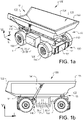
- Fig. 1b is a side view of the same embodiment of the vehicle
- the working machine frame 120 is illustrated as being coupled the propulsions means 160, i.e. the wheels, (via the propulsion axle, which is not seen in this view).
- the illustration shows that the dump body 130 rests on the working machine frame 120. However, in the illustrated embodiment, it is not in contact with the frame 120 during its whole length, but rather at the load dumping side 12 at an attachment means 121 being a pivotal arrangement allowing the dump body 130 to pivot relative the frame 120.
- the dump body 130 further rests on the frame 120 at a guiding plate portion 122.
- the tilting arrangement 140 with one of the side's tilting actuators 141 is shown in Fig. 1b .
- the tilting actuator 141 is in one end attached to the frame 120 and in the other end to the dump body 130. Further, the tilting actuator may be extended so that the dump body's opposite end portion 133 is elevated.
- the tilting arrangement 140 comprise two tilting actuators 141 arranged at different sides of the dump body to ensure a stable tilting, and to spread the load on two actuators enabling a lower dimension of the tilting actuators for the same load.
- the working machine 1 extends in at least a longitudinal direction L, a vertical direction V and a transversal direction T.
- the longitudinal direction L is parallel to an intended direction of travel of the working machine 1.
- the transversal direction T is perpendicular to each one of the vertical direction V and the longitudinal direction L. That is, the transversal direction T is parallel to the general extension of the propulsion axles 110.
- the working machine 1 as described above in relation to Figs. 1a and 1b , comprises a coolant system 100 for cooling one or several types of vehicle heat generating components, as will be further described below.
- Fig. 2 there is depicted an example embodiment of a coolant assembly for the vehicle described above in relation to Figs. 1a and 1b . It should be readily appreciated that the example embodiments described herein may also be installed in other types of electric vehicles, electric working machines or the like. For ease of reference, the coolant system may sometimes be denoted as the system 100.
- the vehicle comprises at least a first vehicle heat generating component 70 and a second vehicle heat generating component 80.
- the second vehicle generating component is a battery pack 80.
- vehicle heat generating component refers to a vehicle component that generates thermal energy or heat, e.g. during an operational state of the vehicle. This type of vehicle component typically needs to be cooled in order to guarantee its function in the vehicle.
- the vehicle heat generating component is located on or in the vehicle. Examples of vehicle heat generating components are battery packs, electronic devices, electronic circuits, inverters, including power inverters, i.e. devices that use the battery pack to power electrical appliances, electric motors, DC/DC converters, on-board chargers, hydraulic components, combustion engine(s), charge air coolers (cac), air conditioning systems etc.
- the coolant system 100 comprises a fluid circuit 60 configured to define a fluid passageway for circulating a coolant there through.
- the fluid circuit is here provided in the form of a first supply branch 62 and a second supply branch 64.
- the fluid circuits including the first supply branch 62 and the second supply branch 64 is considered as a common fluid circuit for the vehicle heat generating components, e.g. the battery pack 80 and the first vehicle heat generating component 70.
- the coolant in the example embodiments described herein, is a liquid fluid medium. Accordingly, the term "fluid" in the context of these example embodiments refers to a liquid fluid.
- the type of coolant may, however, vary depending on type of vehicle and type of installation.
- the coolant is water-based.
- the coolant is water-based with the addition of glycols to prevent freezing and other additives to limit corrosion, erosion and cavitation etc.
- the liquid coolant may accordingly be water blended with ethylene glycol, ammonia, or any other suitable liquid coolant.
- the coolant may also be an oil, or a combination of oil and a water-based fluid.
- the coolant may be a fluid such as a gas.
- the system also comprises the coolant.
- the coolant in this example is contained in the fluid circuit 60.
- a liquid coolant is transportable, typically with the aid of pump units 40 and 50, as further described below.
- the coolant system 100 comprises a coolant assembly 10 arranged in the fluid circuit, which is further described hereinafter.
- the coolant assembly is typically configured to discharge the heat to the ambient atmosphere so as to cool the coolant.
- the flow of coolant is in a direction from the coolant assembly to the vehicle heat generating components, and then in a direction from the vehicle heat generating components to the coolant assembly, as indicated by the arrows in e.g. Figs. 2 and also in Fig. 3 .
- the coolant assembly 10 is configured to decrease the temperature of a portion of the coolant to a first temperature and to supply the portion of coolant to the vehicle heat generating component via the first supply branch 62 and further configured to decrease the temperature of a remaining portion of the coolant to a second temperature and to supply the remaining portion of coolant to the battery pack via the second supply branch 64.
- the system further comprises a first pump unit 40 arranged downstream of the coolant assembly in the first supply branch 62 and in fluid communication with the coolant assembly and the vehicle heat generating component.
- the first pump unit 40 is configured to direct the portion of coolant to the first vehicle heat generating component.
- the system comprises a second pump unit 50.
- the second pump unit 50 is arranged downstream of the coolant assembly in the second supply branch 64 and in fluid communication with the coolant assembly and the battery pack 80 (the second heat generating component).
- the second pump unit is configured to direct the remaining portion of coolant to the battery pack.
- downstream and upstream are terms that indicate a direction relative to the flow of the coolant through the fluid circuit 60.
- downstream refers to a direction that generally corresponds to the direction of the flow of coolant
- upstream generally refers to the direction that is opposite of the direction of flow of the coolant.
- downstream refers to a direction that generally corresponds to the direction of the flow of coolant from the coolant assembly
- upstream generally refers to the direction that is opposite of the direction of flow of the coolant from the coolant assembly.
- the direction of flow of the coolant is indicated with arrows in the Figs. 2 and 3 .
- the coolant assembly includes two spaced apart cooler 20 and 30.
- the coolant assembly has a first cooler 20 and a second cooler 30. That is, in the example embodiment as illustrated in Fig. 2 , the coolant assembly 10 comprises the first cooler 20 configured to supply the portion of the coolant at the first temperature to the vehicle heat generating component and the second cooler 30 configured to supply the remaining potion of the coolant at the second temperature to the battery pack (the second vehicle component). Further, the first cooler 20 and the second cooler 30 are separate components arranged in series in the fluid circuit 60. Moreover, as illustrated in Fig. 2 , the first cooler 20 is arranged upstream of the second cooler 30 and in fluid communication with the second cooler.
- the system described in relation to Fig. 2 includes the first pump unit 40 being arranged downstream of the first cooler 20 in the first supply branch 62 of the fluid circuit.
- the first pump unit 40 is in fluid communication with the first cooler and the first vehicle component so that the pump unit 40 is capable of directing coolant from the first cooler to the first vehicle component 70.
- the first pump unit 40 is positioned in-between the first cooler 20 and the first vehicle component 70.
- the second pump unit 50 is arranged downstream of the second cooler 30 in the second supply branch 64 of the fluid circuit.
- the second pump unit 50 is in fluid communication with the second cooler 30 the battery pack 80 so that the second pump unit 50 is capable of directing coolant from the second cooler 30 to the battery pack 80.
- the second pump unit 50 is positioned in-between the second cooler 30 and the battery pack 80.
- the coolant assembly is configured to supply the portion of the coolant to the first vehicle heat generating component 70 and the remaining portion of the coolant to the battery pack 80.
- the pump units may be electrically driven and/or driven by a belt or hydraulically by another machine in the vehicle. Liquid coolant is thus transported by the pump units to the vehicle components, respectively, as described herein.
- the coolant assembly in Fig. 2 may be provided as a single unit comprising the first cooler 20 and the second cooler 30.
- the coolant assembly is a single unit comprising spaced apart first cooler 20 and second cooler 30 in fluid communication with each other. That is, the coolant assembly is provided in the form of an integral unit having spaced apart first cooler 20 and second cooler 30 in fluid communication with each other.
- the example embodiments of the coolant system may be provided in other ways as long as the coolant assembly can be configured to decrease the temperature of a portion of the coolant to the first temperature and to supply the portion of coolant to the first vehicle heat generating component via the first supply branch and further configured to decrease the temperature of a remaining portion of the coolant to the second temperature and to supply the remaining portion of coolant to the second vehicle heat generating component via the second supply branch.
- the coolant assembly comprises two spaced apart coolers 20, 30 that are separate units. That is, each one of the coolers 20, 30 is provided in the form of a single unit. Still, the first cooler 20 and the second cooler 30 are separate components arranged in series in the fluid circuit 60. Moreover, as illustrated in Fig. 3 , the first cooler 20 is arranged upstream of the second cooler 30 and in fluid communication with the second cooler.
- the coolant system in Fig. 3 is described further below.
- the first cooler 20 has an inlet 22 in fluid communication with a return flow path 65.
- the first supply branch 62 and the second supply branch 64 intersects into the return flow path 65.
- the first supply branch 62 and the second supply branch 64 intersects into the return flow path 65 at a location 68 of the fluid circuit 60.
- the coolant system is thus arranged such that the coolant flowing in the first supply branch 62 is returned to the coolant assembly downstream the vehicle component 70, while the flow of coolant in the second supply branch 64 is returned to the coolant assembly downstream the vehicle component 80.
- the portion of coolant in the first supply branch 62 is mixed with the remaining coolant flow from the second supply branch 64 such that both the flow from the first and second supply branches are mixed before returning to the coolant assembly 10.
- the return flow path 65 is thus used as a common inflow to the coolant assembly 10 for the two supply branches 62. 64.
- the first cooler 20 has the inlet 22 being in fluid communication with the first and second vehicle heat generating components, respectively.
- the first cooler has an outlet 24 in fluid communication with the second cooler.
- the first cooler 20 further has another outlet 23 in fluid communication with the first pump unit 40.
- the first cooler 20 may only have one single outlet for fluidly communicating with the second cooler 30 and the first pump unit.
- the first cooler 20 has an outlet in fluid communication with the second cooler 30 and the first pump unit 40 via a fluid passage that is divided into separate fluid passages for the second cooler 30 and the first pump unit 40, respectively. Accordingly, one and the same outlet of the first cooler may be in fluid communication with both the second cooler and the first pump unit.
- the type of fluid communication connection from the first cooler 20 to the second cooler 30 and the first pump unit 40 may vary depending on the design of the coolant assembly 10.
- the first cooler 20 and the second cooler 30 are in fluid communication via an inter-connecting fluid passage 25. That is, the inter-connecting fluid passage 25 inter-connects the outlet 24 of the first cooler 20 with an inlet 32 of the second cooler 30.
- the second cooler has the inlet 32 being in fluid communication with the first cooler 20 and an outlet 34 being in fluid communication with the second pump unit 50.
- the first branch 62 in this example embodiment extends from inlet 23 of the first cooler 20.
- the inlet 23 is thus in fluid communication with the first pump unit 40.
- the second branch 64 extends from the outlet 34 of the second cooler 30. That is, the outlet 34 of the second cooler 30 is in fluid communication with the second pump unit 50.
- the coolant assembly 10 is configured to decrease the temperature of a portion of the coolant to the first temperature in the first cooler 20 and to supply the portion of coolant to the first vehicle heat generating component via the first supply branch 62 and further configured to decrease the temperature of a remaining portion of the coolant to the second temperature in the second cooler 30 and to supply the remaining portion of coolant to the battery pack via the second supply branch 64.
- the coolant assembly is configured to decrease the temperature of the portion of the coolant to the first temperature in a first stage at a first part of the coolant assembly, and to decrease the temperature of the remaining portion of the coolant to the second temperature in a following stage at a second part of the coolant assembly.
- first and second parts of the coolant assembly are in fluid communication with each other.
- first and second parts of the coolant assembly are in fluid communication with each other via an internal fluid passage of the coolant assembly.
- first and second parts of the coolant assembly may be in fluid communication with each other in other ways.
- the second temperature is a lower temperature than the first temperature.
- the various temperatures may be measured by temperature sensors (not shown) arranged in the system. That is, the measured temperature may be measured by means of a temperature measuring device.
- data indicative of the temperatures may be transferred to a control unit, as mentioned hereinafter.
- the battery pack typically requires a lower coolant temperature than other vehicle heat generating components such as electric components, and also lower coolant temperature than e.g. internal combustion engines.
- the system as described above in relation to Fig. 2 will provide two temperature levels.
- the system provides one level for the first vehicle heat generating component 70 via coolant in the first supply branch 62.
- the first vehicle heat generating component may be an inverter, electrical machine (EM) or the like.
- the first supply branch (or part of the circuit) may for example have an inlet temperature of approximate 65-70 degrees C. It should be noted that other temperature intervals are likewise conceivable.
- the system provides another temperature level for the second vehicle heat generating component 80 via coolant in the second supply branch 64.
- the second vehicle heat generating component may be the battery pack, i.e. a battery circuit.
- the second supply branch (or part of the circuit) may for example have an inlet temperature of approximate 40-50 degrees C. It should be noted that other temperature intervals are likewise conceivable.
- the cooler is a heat exchanger, e.g. a radiator.
- each one of the first cooler and the second cooler is adapted to at least transfer thermal energy from one medium to another for the purpose of cooling the coolant supplied to it.
- the heat exchanger should be dimensioned in view of the function, space and installation in the vehicle. Radiators can be provided in several different ways and are commercially available in various configurations.
- the pump units in the system are intended for directing and circulating the coolant in the closed circuit.
- the circulating coolant absorbs heat from heat generating components, e.g. the battery pack, and releases heat via the coolant assembly, e.g. the first cooler and the second cooler.
- the coolant assembly e.g. the first cooler and the second cooler.
- the coolant assembly first and second coolers
- the ambient air flow is being blown by one or several fan(s).
- the first cooler and the second cooler are typically air-to-coolant heat exchangers in which a fan is used to produce an air flow through the heat exchangers in order to cool the coolant.
- a fan is used to produce an air flow through the heat exchangers in order to cool the coolant.
- the first and second coolers are arranged in close proximity to each other, they may be cooled at least partially by the same air flow.
- the first and the second coolers are in this example arranged to be cooled by a common air flow fan. By such an arrangement only one fan may be needed.
- the system may also include one or several fans behind the coolant assembly in order to improve the cooling performance.
- the fan is adapted to direct or force air through the cooler such as a radiator, when insufficient air is passing through the radiator to achieve the desired level of cooling, for example when the vehicle is not moving.
- the system comprises one fan configured to direct air towards the coolant assembly.
- the system comprises a plurality of fans arranged in series, on in parallel, each one being configured to direct air towards the coolant assembly.
- the coolant assembly includes the first cooler and the second cooler, there is one fan arranged in connection with each one of the coolers. That is, the system comprises a first fan configured to direct air towards the first cooler and a second fan configured to direct air towards the second cooler.
- the arrangement of the fan(s) can be varied in several different manners.
- the fan, its components and configurations of the fan are well-known components and thus not further described herein.
- the battery pack 80 is typically also cooled by circulation of water based coolant through cooling passages within the battery structure of the battery pack.
- the coolant can be used to remove heat from the battery pack and also to provide heating of the pack for fast charging at low temperatures, and/or for more rapid cold start.
- some of them may further be mounted to cold plates (not shown), which are used to transfer the heat away from the electronics and into the liquid coolant contained in the fluid circuit.
- Fig 3 there is depicted another example embodiment of the coolant system, which is intended for installation in a vehicle as described in relation to Fig. 1a above, or in any other type of vehicle or working machine.
- the first cooler 20 and the second cooler 30 are in fluid communication via an inter-connecting fluid passage 25'. That is, the inter-connecting fluid passage 25' inter-connects an outlet 24' of the first cooler 20 with an inlet 32' of the second cooler 30.
- the first cooler 20 has an inlet 22' in fluid communication with the return flow path 65 and an outlet 24' in fluid communication with the second cooler 30 and the first pump unit 40. That is, the first cooler 20 has the inlet 22' being in fluid communication with the first and second vehicle heat generating components 70, 80. Further, in this example, when the system includes a number of vehicle heat generating components 70, the first cooler 20 has the inlet 22' being in fluid communication with the number of the vehicle heat generating components 70, 80. In addition, as illustrated in Fig. 3 , one and the same outlet 24' of the first cooler is in fluid communication with both the second cooler 30 and the first pump unit 40.
- first branch 62 in this example embodiment extends from the inter-connecting fluid passage 25' connecting the first cooler 20 with the second cooler 40, as shown in Fig. 3 .
- the first branch 62 extends from a location 26 on the inter-connecting fluid passage 25 to the first pump unit 40.
- the second branch 64 extends from an outlet 34' of the second cooler 30. That is, the outlet 34' of the second cooler 30 is in fluid communication with the second pump unit 50.
- the second cooler 30 has the inlet 32' in fluid communication with the first cooler 20 and the outlet 34' in fluid communication with the second pump unit 40.
- the first cooler 20 is configured to decrease the temperature of the (first) portion of the coolant to the first temperature and to supply the portion of coolant to the first vehicle heat generating component 70 via the first supply branch 62 of the fluid circuit 60.
- the second cooler 30 is in this example configured to decrease the temperature of the remaining portion of the coolant to a second temperature and to supply the remaining portion of coolant to the second vehicle heat generating component 80 via the second supply branch 64 of the fluid circuit.
- the system in Fig. 3 comprises the first pump unit 40 being arranged downstream of the coolant assembly in the first supply branch 62 and in fluid communication with the coolant assembly and the first vehicle heat generating component.
- the first pump unit 40 is arranged downstream of the first cooler 20 in the first supply branch 62 and in fluid communication with the first cooler 20 and the first vehicle heat generating component 70.
- the system in Fig. 3 comprises the second pump unit 50 being arranged downstream of the coolant assembly in the second supply branch 64 and in fluid communication with the coolant assembly and the second vehicle heat generating component 80.
- the second pump unit 50 is arranged downstream of the second cooler 30 in the second supply branch 64 and in fluid communication with the second cooler 30 and the second vehicle heat generating component 80.
- the system further comprises a controllable valve 90 for directing the flow of coolant and a heater 46 for heating the coolant.
- the controllable valve 90 is arranged upstream of the coolant assembly in the return flow path 65 of the fluid circuit 60.
- the controllable valve 90 is arranged upstream of the first cooler 20 and in the return flow path 65 of the fluid circuit 60.
- the first supply branch 62 and the second supply branch 64 intersects into the return flow path 65 upstream of the controllable valve 90.
- the controllable valve is in fluid communication with the coolant assembly 10 and the heater 46.
- the heater 46 is arranged in a by-pass branch 44 extending from the controllable valve 90.
- the by-pass branch 44 extends from the controllable valve 90 to any one of the first and second supply branches 62 and 64.
- the heater 46 is in fluid communication with the controllable valve 90 and any one of the battery pack 80 and the vehicle heat generating component 70. In this manner, the controllable valve can control the flow of coolant to the coolant assembly 10 and the heater 46.
- the heater 46 is in fluid communication with the controllable valve 90 and both the battery pack 80 and the vehicle heat generating component 70. In this manner, the controllable valve can control the flow of coolant to the coolant assembly 10 and the heater 46.
- the by-pass branch 44 extends from the controllable valve 90 to the first and second supply branches 62 and 64, respectively.
- the heater 46 is in fluid communication with the controllable valve 90 and the battery pack 80, only.
- the heater 46 is arranged in a by-pass branch 44 extending from the controllable valve 90 to the second supply branch 64.
- the heater may be an electric heater which uses the same line voltage as the other electric components in the vehicle, which line voltage is usually 24 V for trucks, busses and construction equipment and 12V for passenger cars.
- the line voltage may in other examples be 400 V, 600 V.
- the controllable valve can be provided in the form of an on/off valve, non-return valve, check valve or the like.
- the system according to this example embodiment is designed such that the controllable valve is disposed in the return flow path 65 and arranged to receive the return flow of coolant from the first and second vehicle heat generating components, respectively.
- the coolant system 100 may comprise an expansion device 92 to allow the coolant to expand with rising temperature and pressure.
- the expansion device is in fluid communication with the second branch 64.
- the second cooler 2 is in fluid communication with the expansion device 92.
- the expansion device can be designed in several different manners.
- the device 92 has an inner volume for containing the coolant. That is, in one example, the coolant system 100 comprises the expansion device 92 having an inner volume to allow the coolant to expand with rising temperature and pressure.
- the system as described above in relation to Fig. 3 will provide two temperature levels.
- the system in Fig. 3 provides one level for the set of the first vehicle heat generating components 70 via coolant in the first supply branch 62.
- the first vehicle heat generating components may be any one of an inverter, electrical machine (EM) or the like.
- the first supply branch 62 (or part of the circuit) may for example have an inlet temperature of approximate 65-70 degrees C. It should be noted that other temperature intervals are likewise conceivable.
- the system provides another temperature level for the set of the second vehicle heat generating components 80 via coolant in the second supply branch 64.
- the second vehicle heat generating component may typically be a number of battery packs, i.e. a battery circuit.
- the second supply branch 64 (or part of the circuit) may for example have an inlet temperature of approximate 40-50 degrees C. It should be noted that other temperature intervals are likewise conceivable.
- FIG. 3 there is also another vehicle heat generating component 82 disposed in the second supply branch 64.
- the vehicle heat generating component 82 is disposed downstream of the second vehicle heat generating component 80 in the second supply branch 64.
- the controllable valve 90 is configured to control the flow of coolant and to control if the vehicle heat generating components need to be cooled or heated. If the vehicle heat generating components 70, 80, 82 need to be heated, the controllable valve 90 is configured to direct the flow of coolant to the heater rather than returning the coolant to the coolant assembly 10. If the vehicle heat generating components need to be cooled, the controllable valve 90 will direct the flow to the coolers 20 and 30, respectively. Furthermore, if the controllable valve 90 has directed the flow to the heater 46 in the by-pass branch 44, both pumps 40 and 50 will take coolant after the heater.
- the pump unit 40 takes coolant between the coolers 20 and 30, meaning that this coolant has only passed one cooler 20.
- the flow from pump 40 is then entering the vehicle heat generating components 70 (e.g. an inverter and an EM circuit).
- the pump unit 50 takes the coolant after the cooler 30, meaning that this coolant has passed both coolers 20 and 30 to lower the temperature of the coolant as much as possible.
- the flows are summed up to one flow before the controllable valve 90 in the return path 65.
- the coolant system By way of example, if one of the circuits of vehicle heat generating components has a high cooling demand and the other one has low cooling demand, it becomes possible by the example embodiments of the coolant system to deliver different coolant temperature to the circuit of vehicle heat generating components.
- the circuit of component with low demand will aid the circuit of component with high demand because of the mixture of coolant temperatures.
- Another example advantage with the system 100 is that flow of coolant through the first cooler 20 is higher than the flow of coolant through the second cooler 30, partly because the first cooler 20 should reduce as much energy as possible. Reducing energy is considered easier when the temperature between the air and the coolant is greater. Because of the higher flow through the first cooler 20, the temperature difference between inlet 22 (and inlet 22' in Fig.
- the first cooler 20 is set to operate with a higher utilization.
- the second cooler 30 is then set to reduce the temperature of the remaining coolant flowing through the second cooler 30 as much as possible to deliver the low temperature coolant to the second heat generating component 80, i.e. the battery circuit.
- the system 100 comprises the control unit 78.
- the control unit is connectable to the coolant assembly. That is, the control unit 78 is adapted to control the coolant assembly.
- the control unit is adapted to set the level of the first and second temperatures, as mentioned above.
- the control unit 78 may also communicate with the controllable valve 90 so as to control the valve, as mentioned above.
- the control unit is adapted to control the valve to selectively direct the flow of fluid to the coolant assembly and the heater in the by-pass branch.
- control unit is a part of another system in the vehicle.
- vehicle comprises the control unit to perform the operational steps of controlling the coolant system in order to perform the temperature control according to the example embodiments as described herein.
- control unit may be arranged in another remote location of the vehicle.
- the example embodiments of the coolant system 100 as described in relation to Figs. 2 and 3 are to be installed in a vehicle, e.g. an electric vehicle, in particular an electric machine as described in relation to Figs. 1a- 1b .
- the vehicle preferably an electric vehicle
- the vehicle comprises the coolant system according to any one of the example embodiments as described above in relation to Figs. 2 and 3 .
- the vehicle preferably an electric vehicle, comprises an electric vehicle thermal management system having a coolant system according to any one of the examples above and at least including the battery pack and a vehicle heat generating component in fluid communication with the coolant assembly.
- the electric vehicle thermal management system and/or the coolant system may include a number of vehicle heat generating components, and not only two vehicle heat generating components.
Landscapes
- Engineering & Computer Science (AREA)
- Power Engineering (AREA)
- Mechanical Engineering (AREA)
- Transportation (AREA)
- Chemical & Material Sciences (AREA)
- Manufacturing & Machinery (AREA)
- Chemical Kinetics & Catalysis (AREA)
- Electrochemistry (AREA)
- General Chemical & Material Sciences (AREA)
- Sustainable Energy (AREA)
- Sustainable Development (AREA)
- Life Sciences & Earth Sciences (AREA)
- Combustion & Propulsion (AREA)
- Cooling, Air Intake And Gas Exhaust, And Fuel Tank Arrangements In Propulsion Units (AREA)
- Arrangement Or Mounting Of Propulsion Units For Vehicles (AREA)
- Electric Propulsion And Braking For Vehicles (AREA)
Claims (10)
- Système de réfrigérant (100) pour véhicule électrique (1), le véhicule comprenant au moins un premier composant générateur thermique de véhicule (70) et un second composant générateur thermique de véhicule (80), ledit système de réfrigérant comprenant un circuit de fluide (60) configuré pour définir un passage de fluide pour faire circuler un réfrigérant à travers un ensemble réfrigérant (10) disposé dans ledit circuit de fluide, ledit ensemble réfrigérant étant configuré pour diminuer la température d'une partie du réfrigérant jusqu'à une première température et pour fournir la partie de réfrigérant au premier composant générateur thermique de véhicule par l'intermédiaire d'une première branche d'alimentation (62) du circuit de fluide et en outre configuré pour diminuer la température d'une partie restante du réfrigérant jusqu'à une seconde température et pour fournir la partie restante de réfrigérant au second composant générateur thermique de véhicule par l'intermédiaire d'une seconde branche d'alimentation (64) du circuit de fluide, ledit système comprenant en outre une première unité de pompe (40) disposée en aval dudit ensemble réfrigérant dans ladite première branche d'alimentation (62) et en communication fluidique avec ledit ensemble réfrigérant et ledit premier composant générateur thermique de véhicule, ladite première unité de pompe étant configurée pour diriger ladite partie de réfrigérant vers ledit premier composant générateur thermique de véhicule, et une seconde unité de pompe (50) disposée en aval dudit ensemble réfrigérant dans ladite seconde branche d'alimentation (64) et en communication fluidique avec ledit ensemble réfrigérant et ledit second composant générateur thermique de véhicule, la dite seconde unité de pompe étant configurée pour diriger ladite partie restante de réfrigérant vers ledit second composant générateur thermique de véhicule, et caractérisé en ce que ledit système comprend en outre une vanne contrôlable (90) pour diriger le flux de réfrigérant et un chauffage (46) pour chauffer le réfrigérant, ladite vanne contrôlable (90) étant disposée en amont dudit ensemble réfrigérant dans un passage de flux de retour (65) dudit circuit de fluide, ladite première branche d'alimentation et ladite seconde branche d'alimentation se coupant dans ledit passage de flux de retour (65) en amont de ladite vanne contrôlable (90), ladite vanne contrôlable étant en outre en communication fluidique avec ledit ensemble réfrigérant et ledit chauffage (46), et ledit chauffage étant disposé dans une branche de contournement (44) s'étendant depuis ladite vanne contrôlable et en communication fluidique avec ladite vanne contrôlable et l'un quelconque parmi le premier composant générateur thermique de véhicule et le second composant générateur thermique de véhicule, de sorte que ladite vanne contrôlable peut commander le flux de réfrigérant vers l'ensemble réfrigérant et le chauffage.
- Système de réfrigérant selon la revendication 1, dans lequel ledit ensemble réfrigérant est configuré pour diminuer la température de la partie du réfrigérant jusqu'à la première température dans un premier stade au niveau d'une première pièce de l'ensemble réfrigérant, et pour diminuer la température de la partie restante du réfrigérant jusqu'à la seconde température dans un stade suivant au niveau d'une seconde pièce de l'ensemble réfrigérant, lesdites première et seconde pièces de l'ensemble réfrigérant étant en communication fluidique l'une avec l'autre.
- Système de réfrigérant selon la revendication 1, dans lequel ledit ensemble réfrigérant comprend un premier dispositif réfrigérant (20) configuré pour fournir la partie du réfrigérant à la première température au premier composant générateur thermique de véhicule et un second dispositif réfrigérant (30) configuré pour fournir la partie restante du réfrigérant à la seconde température audit second composant générateur thermique de véhicule, le premier dispositif réfrigérant et le second dispositif réfrigérant étant des composants séparés disposés en série dans le circuit de fluide, le premier dispositif réfrigérant étant disposé en amont dudit second dispositif réfrigérant et en communication fluidique avec ledit second dispositif réfrigérant.
- Système de réfrigérant selon la revendication 3, dans lequel ledit premier dispositif réfrigérant comporte une entrée en communication fluidique avec lesdits premier et second composants générateurs thermiques de véhicule respectivement, et une sortie en communication fluidique avec le second dispositif réfrigérant et la première unité de pompe, alors que ledit second dispositif réfrigérant comporte une entrée en communication fluidique avec le premier dispositif réfrigérant et une sortie en communication fluidique avec la seconde unité de pompe.
- Système de réfrigérant selon l'une quelconque des revendications précédentes, dans lequel le système de réfrigérant comprend un dispositif d'expansion (92) ayant un volume intérieur de nature à permettre au réfrigérant de se dilater au fur et à mesure de l'augmentation de la température et de la pression.
- Système de réfrigérant selon l'une quelconque des revendications précédentes, dans lequel le second composant générateur thermique de véhicule est un pack de batteries.
- Système de réfrigérant selon l'une quelconque des revendications précédentes, dans lequel ledit système comprend en outre une unité de commande (78) adaptée au contrôle dudit ensemble réfrigérant.
- Système de réfrigérant selon la revendication 7, dans lequel ladite unité de commande est apte à fixer le niveau des première et seconde températures.
- Système de gestion thermique de véhicule électrique comprenant un système de réfrigérant selon l'une quelconque des revendications précédentes et au moins un pack de batteries et un composant générateur thermique de véhicule en communication fluidique avec ledit ensemble réfrigérant.
- Véhicule, de préférence véhicule électrique, comprenant un système de réfrigérant selon l'une quelconque des revendications 1 à 8 et/ou système de gestion thermique de véhicule électrique selon la revendication 9.
Applications Claiming Priority (1)
| Application Number | Priority Date | Filing Date | Title |
|---|---|---|---|
| PCT/EP2017/081656 WO2019110093A1 (fr) | 2017-12-06 | 2017-12-06 | Système de réfrigérant pour véhicule |
Publications (2)
| Publication Number | Publication Date |
|---|---|
| EP3720732A1 EP3720732A1 (fr) | 2020-10-14 |
| EP3720732B1 true EP3720732B1 (fr) | 2022-08-10 |
Family
ID=60702680
Family Applications (1)
| Application Number | Title | Priority Date | Filing Date |
|---|---|---|---|
| EP17816620.3A Active EP3720732B1 (fr) | 2017-12-06 | 2017-12-06 | Système de réfrigérant pour véhicule |
Country Status (4)
| Country | Link |
|---|---|
| US (1) | US11318861B2 (fr) |
| EP (1) | EP3720732B1 (fr) |
| CN (1) | CN111406001B (fr) |
| WO (1) | WO2019110093A1 (fr) |
Families Citing this family (3)
| Publication number | Priority date | Publication date | Assignee | Title |
|---|---|---|---|---|
| CN113054261A (zh) * | 2019-12-26 | 2021-06-29 | 奥动新能源汽车科技有限公司 | 冷却组件及包括其的充换电站、储能站 |
| DE102020212968A1 (de) | 2020-10-14 | 2022-04-14 | Zf Friedrichshafen Ag | Antriebsstrang für eine Arbeitsmaschine, Verfahren zum Betreiben des Antriebsstrangs und Arbeitsmaschine |
| EP4155106A1 (fr) * | 2021-09-22 | 2023-03-29 | Volvo Truck Corporation | Système de refroidissement pour véhicule |
Family Cites Families (13)
| Publication number | Priority date | Publication date | Assignee | Title |
|---|---|---|---|---|
| FR2461101A1 (fr) | 1979-08-06 | 1981-01-30 | Alsacienne Constr Meca | Dispositif de regulation de l'air de suralimentation des moteurs diesel |
| FR2816258B1 (fr) * | 2000-11-09 | 2003-02-14 | Valeo Thermique Moteur Sa | Dispositif de refroidissement d'un vehicule a moteur electrique alimente par une pile a combustible |
| DE60216049T2 (de) | 2001-01-05 | 2007-07-05 | Renault S.A.S. | Vorrichtung, system und verfahren zum kühlen eines kühlmittels |
| US20090249807A1 (en) * | 2008-04-04 | 2009-10-08 | Gm Global Technology Operations, Inc. | HVAC and Battery Thermal Management for a Vehicle |
| US8215432B2 (en) * | 2008-05-09 | 2012-07-10 | GM Global Technology Operations LLC | Battery thermal system for vehicle |
| DE102012217101B4 (de) | 2012-09-24 | 2016-09-01 | Bayerische Motoren Werke Aktiengesellschaft | Kühlmittelkreislauf für Fahrzeuge |
| US9631872B2 (en) * | 2013-02-04 | 2017-04-25 | GM Global Technology Operations LLC | Multi-circuited vehicular thermal management system and method |
| DE102013209045B4 (de) * | 2013-05-15 | 2022-10-27 | Bayerische Motoren Werke Aktiengesellschaft | Kühlsystem für ein Hybridfahrzeug sowie Verfahren zum Betrieb eines derartigen Kühlsystems |
| US9515357B2 (en) * | 2014-01-15 | 2016-12-06 | Ford Global Technologies, Llc | Battery thermal management system for electrified vehicle |
| US10286774B2 (en) | 2014-04-18 | 2019-05-14 | Ford Global Technologies, Llc | Multiple zoned radiator |
| US10573940B2 (en) * | 2015-02-25 | 2020-02-25 | Ford Global Technologies, Llc | Battery thermal management system |
| CN107351622B (zh) * | 2016-05-10 | 2019-11-08 | 比亚迪股份有限公司 | 汽车热管理系统和电动汽车 |
| KR102382721B1 (ko) * | 2017-09-27 | 2022-04-05 | 한온시스템 주식회사 | 자동차의 통합 열관리 시스템 |
-
2017
- 2017-12-06 WO PCT/EP2017/081656 patent/WO2019110093A1/fr unknown
- 2017-12-06 EP EP17816620.3A patent/EP3720732B1/fr active Active
- 2017-12-06 CN CN201780097195.8A patent/CN111406001B/zh active Active
- 2017-12-06 US US16/769,259 patent/US11318861B2/en active Active
Also Published As
| Publication number | Publication date |
|---|---|
| US20210188126A1 (en) | 2021-06-24 |
| CN111406001A (zh) | 2020-07-10 |
| CN111406001B (zh) | 2023-04-07 |
| EP3720732A1 (fr) | 2020-10-14 |
| WO2019110093A1 (fr) | 2019-06-13 |
| US11318861B2 (en) | 2022-05-03 |
Similar Documents
| Publication | Publication Date | Title |
|---|---|---|
| US9827846B2 (en) | Traction battery cooling system | |
| EP3088230B1 (fr) | Système de commande thermique multimode d'un véhicule électrique | |
| CN111315609B (zh) | 用于机动车的冷却系统和具有这种冷却系统的机动车 | |
| US9844995B2 (en) | EV muti-mode thermal control system | |
| US20160344075A1 (en) | Thermal Management System for a Vehicle | |
| US8342279B1 (en) | Modular vehicle and associated method of construction | |
| US20160318409A1 (en) | EV Muti-Mode Thermal Control System | |
| EP3720732B1 (fr) | Système de réfrigérant pour véhicule | |
| US20160351981A1 (en) | Cooling modes to manage a high voltage battery for a vehicle | |
| KR102390858B1 (ko) | 하이브리드식 작업 기계 | |
| CN101010215A (zh) | 用于混合机车和非公路车辆的高温电力储存电池系统 | |
| CN112758062B (zh) | 车辆的组合式冷却和水制动系统及冷却车辆的推进装置和水制动车辆的一对车轮的方法 | |
| CN103380048A (zh) | 混合型车辆传动系冷却系统 | |
| CN102689586A (zh) | 一种用于电动汽车的一体化温度控制系统 | |
| CN112238727A (zh) | 车辆的热管理系统及集成热管理模块 | |
| US20160318410A1 (en) | EV Muti-Mode Thermal Control System | |
| JP2014092160A (ja) | エンジン作動型ユニット用の統合冷却システム及び方法 | |
| US20230331119A1 (en) | Coolant distribution manifold, propulsion battery cooling system, and vehicle | |
| CN114435189A (zh) | 具有电池旁路回路的电动化车辆热管理系统 | |
| EP4212371A1 (fr) | Système de gestion thermique pour un véhicule | |
| CN113530661A (zh) | 冷却系统 | |
| US10153523B2 (en) | Traction battery thermal management method and system | |
| CN114174108B (zh) | 车辆用冷却装置 | |
| CN109649218B (zh) | 使用储热器的混合动力和全电动车辆的电池热管理系统 | |
| EP4155142A1 (fr) | Système de gestion d'énergie de véhicule, véhicule comprenant un tel système de gestion d'énergie de véhicule, et procédé de commande d'un système de gestion d'énergie de véhicule |
Legal Events
| Date | Code | Title | Description |
|---|---|---|---|
| STAA | Information on the status of an ep patent application or granted ep patent |
Free format text: STATUS: UNKNOWN |
|
| STAA | Information on the status of an ep patent application or granted ep patent |
Free format text: STATUS: THE INTERNATIONAL PUBLICATION HAS BEEN MADE |
|
| PUAI | Public reference made under article 153(3) epc to a published international application that has entered the european phase |
Free format text: ORIGINAL CODE: 0009012 |
|
| STAA | Information on the status of an ep patent application or granted ep patent |
Free format text: STATUS: REQUEST FOR EXAMINATION WAS MADE |
|
| 17P | Request for examination filed |
Effective date: 20200604 |
|
| AK | Designated contracting states |
Kind code of ref document: A1 Designated state(s): AL AT BE BG CH CY CZ DE DK EE ES FI FR GB GR HR HU IE IS IT LI LT LU LV MC MK MT NL NO PL PT RO RS SE SI SK SM TR |
|
| AX | Request for extension of the european patent |
Extension state: BA ME |
|
| DAV | Request for validation of the european patent (deleted) | ||
| DAX | Request for extension of the european patent (deleted) | ||
| GRAP | Despatch of communication of intention to grant a patent |
Free format text: ORIGINAL CODE: EPIDOSNIGR1 |
|
| STAA | Information on the status of an ep patent application or granted ep patent |
Free format text: STATUS: GRANT OF PATENT IS INTENDED |
|
| INTG | Intention to grant announced |
Effective date: 20220303 |
|
| GRAS | Grant fee paid |
Free format text: ORIGINAL CODE: EPIDOSNIGR3 |
|
| GRAA | (expected) grant |
Free format text: ORIGINAL CODE: 0009210 |
|
| STAA | Information on the status of an ep patent application or granted ep patent |
Free format text: STATUS: THE PATENT HAS BEEN GRANTED |
|
| AK | Designated contracting states |
Kind code of ref document: B1 Designated state(s): AL AT BE BG CH CY CZ DE DK EE ES FI FR GB GR HR HU IE IS IT LI LT LU LV MC MK MT NL NO PL PT RO RS SE SI SK SM TR |
|
| REG | Reference to a national code |
Ref country code: AT Ref legal event code: REF Ref document number: 1510279 Country of ref document: AT Kind code of ref document: T Effective date: 20220815 Ref country code: CH Ref legal event code: EP |
|
| REG | Reference to a national code |
Ref country code: DE Ref legal event code: R096 Ref document number: 602017060553 Country of ref document: DE |
|
| REG | Reference to a national code |
Ref country code: IE Ref legal event code: FG4D |
|
| REG | Reference to a national code |
Ref country code: NL Ref legal event code: MP Effective date: 20220810 |
|
| REG | Reference to a national code |
Ref country code: LT Ref legal event code: MG9D |
|
| PG25 | Lapsed in a contracting state [announced via postgrant information from national office to epo] |
Ref country code: SE Free format text: LAPSE BECAUSE OF FAILURE TO SUBMIT A TRANSLATION OF THE DESCRIPTION OR TO PAY THE FEE WITHIN THE PRESCRIBED TIME-LIMIT Effective date: 20220810 Ref country code: RS Free format text: LAPSE BECAUSE OF FAILURE TO SUBMIT A TRANSLATION OF THE DESCRIPTION OR TO PAY THE FEE WITHIN THE PRESCRIBED TIME-LIMIT Effective date: 20220810 Ref country code: PT Free format text: LAPSE BECAUSE OF FAILURE TO SUBMIT A TRANSLATION OF THE DESCRIPTION OR TO PAY THE FEE WITHIN THE PRESCRIBED TIME-LIMIT Effective date: 20221212 Ref country code: NO Free format text: LAPSE BECAUSE OF FAILURE TO SUBMIT A TRANSLATION OF THE DESCRIPTION OR TO PAY THE FEE WITHIN THE PRESCRIBED TIME-LIMIT Effective date: 20221110 Ref country code: NL Free format text: LAPSE BECAUSE OF FAILURE TO SUBMIT A TRANSLATION OF THE DESCRIPTION OR TO PAY THE FEE WITHIN THE PRESCRIBED TIME-LIMIT Effective date: 20220810 Ref country code: LV Free format text: LAPSE BECAUSE OF FAILURE TO SUBMIT A TRANSLATION OF THE DESCRIPTION OR TO PAY THE FEE WITHIN THE PRESCRIBED TIME-LIMIT Effective date: 20220810 Ref country code: LT Free format text: LAPSE BECAUSE OF FAILURE TO SUBMIT A TRANSLATION OF THE DESCRIPTION OR TO PAY THE FEE WITHIN THE PRESCRIBED TIME-LIMIT Effective date: 20220810 Ref country code: FI Free format text: LAPSE BECAUSE OF FAILURE TO SUBMIT A TRANSLATION OF THE DESCRIPTION OR TO PAY THE FEE WITHIN THE PRESCRIBED TIME-LIMIT Effective date: 20220810 |
|
| REG | Reference to a national code |
Ref country code: AT Ref legal event code: MK05 Ref document number: 1510279 Country of ref document: AT Kind code of ref document: T Effective date: 20220810 |
|
| PG25 | Lapsed in a contracting state [announced via postgrant information from national office to epo] |
Ref country code: PL Free format text: LAPSE BECAUSE OF FAILURE TO SUBMIT A TRANSLATION OF THE DESCRIPTION OR TO PAY THE FEE WITHIN THE PRESCRIBED TIME-LIMIT Effective date: 20220810 Ref country code: IS Free format text: LAPSE BECAUSE OF FAILURE TO SUBMIT A TRANSLATION OF THE DESCRIPTION OR TO PAY THE FEE WITHIN THE PRESCRIBED TIME-LIMIT Effective date: 20221210 Ref country code: HR Free format text: LAPSE BECAUSE OF FAILURE TO SUBMIT A TRANSLATION OF THE DESCRIPTION OR TO PAY THE FEE WITHIN THE PRESCRIBED TIME-LIMIT Effective date: 20220810 Ref country code: GR Free format text: LAPSE BECAUSE OF FAILURE TO SUBMIT A TRANSLATION OF THE DESCRIPTION OR TO PAY THE FEE WITHIN THE PRESCRIBED TIME-LIMIT Effective date: 20221111 |
|
| PG25 | Lapsed in a contracting state [announced via postgrant information from national office to epo] |
Ref country code: SM Free format text: LAPSE BECAUSE OF FAILURE TO SUBMIT A TRANSLATION OF THE DESCRIPTION OR TO PAY THE FEE WITHIN THE PRESCRIBED TIME-LIMIT Effective date: 20220810 Ref country code: RO Free format text: LAPSE BECAUSE OF FAILURE TO SUBMIT A TRANSLATION OF THE DESCRIPTION OR TO PAY THE FEE WITHIN THE PRESCRIBED TIME-LIMIT Effective date: 20220810 Ref country code: ES Free format text: LAPSE BECAUSE OF FAILURE TO SUBMIT A TRANSLATION OF THE DESCRIPTION OR TO PAY THE FEE WITHIN THE PRESCRIBED TIME-LIMIT Effective date: 20220810 Ref country code: DK Free format text: LAPSE BECAUSE OF FAILURE TO SUBMIT A TRANSLATION OF THE DESCRIPTION OR TO PAY THE FEE WITHIN THE PRESCRIBED TIME-LIMIT Effective date: 20220810 Ref country code: CZ Free format text: LAPSE BECAUSE OF FAILURE TO SUBMIT A TRANSLATION OF THE DESCRIPTION OR TO PAY THE FEE WITHIN THE PRESCRIBED TIME-LIMIT Effective date: 20220810 Ref country code: AT Free format text: LAPSE BECAUSE OF FAILURE TO SUBMIT A TRANSLATION OF THE DESCRIPTION OR TO PAY THE FEE WITHIN THE PRESCRIBED TIME-LIMIT Effective date: 20220810 |
|
| REG | Reference to a national code |
Ref country code: DE Ref legal event code: R097 Ref document number: 602017060553 Country of ref document: DE |
|
| PG25 | Lapsed in a contracting state [announced via postgrant information from national office to epo] |
Ref country code: SK Free format text: LAPSE BECAUSE OF FAILURE TO SUBMIT A TRANSLATION OF THE DESCRIPTION OR TO PAY THE FEE WITHIN THE PRESCRIBED TIME-LIMIT Effective date: 20220810 Ref country code: EE Free format text: LAPSE BECAUSE OF FAILURE TO SUBMIT A TRANSLATION OF THE DESCRIPTION OR TO PAY THE FEE WITHIN THE PRESCRIBED TIME-LIMIT Effective date: 20220810 |
|
| PLBE | No opposition filed within time limit |
Free format text: ORIGINAL CODE: 0009261 |
|
| STAA | Information on the status of an ep patent application or granted ep patent |
Free format text: STATUS: NO OPPOSITION FILED WITHIN TIME LIMIT |
|
| PG25 | Lapsed in a contracting state [announced via postgrant information from national office to epo] |
Ref country code: AL Free format text: LAPSE BECAUSE OF FAILURE TO SUBMIT A TRANSLATION OF THE DESCRIPTION OR TO PAY THE FEE WITHIN THE PRESCRIBED TIME-LIMIT Effective date: 20220810 |
|
| 26N | No opposition filed |
Effective date: 20230511 |
|
| REG | Reference to a national code |
Ref country code: CH Ref legal event code: PL |
|
| REG | Reference to a national code |
Ref country code: BE Ref legal event code: MM Effective date: 20221231 |
|
| PG25 | Lapsed in a contracting state [announced via postgrant information from national office to epo] |
Ref country code: SI Free format text: LAPSE BECAUSE OF FAILURE TO SUBMIT A TRANSLATION OF THE DESCRIPTION OR TO PAY THE FEE WITHIN THE PRESCRIBED TIME-LIMIT Effective date: 20220810 Ref country code: LU Free format text: LAPSE BECAUSE OF NON-PAYMENT OF DUE FEES Effective date: 20221206 |
|
| PG25 | Lapsed in a contracting state [announced via postgrant information from national office to epo] |
Ref country code: LI Free format text: LAPSE BECAUSE OF NON-PAYMENT OF DUE FEES Effective date: 20221231 Ref country code: IE Free format text: LAPSE BECAUSE OF NON-PAYMENT OF DUE FEES Effective date: 20221206 Ref country code: CH Free format text: LAPSE BECAUSE OF NON-PAYMENT OF DUE FEES Effective date: 20221231 |
|
| PG25 | Lapsed in a contracting state [announced via postgrant information from national office to epo] |
Ref country code: BE Free format text: LAPSE BECAUSE OF NON-PAYMENT OF DUE FEES Effective date: 20221231 |
|
| PGFP | Annual fee paid to national office [announced via postgrant information from national office to epo] |
Ref country code: GB Payment date: 20231219 Year of fee payment: 7 |
|
| PGFP | Annual fee paid to national office [announced via postgrant information from national office to epo] |
Ref country code: FR Payment date: 20231226 Year of fee payment: 7 |
|
| PG25 | Lapsed in a contracting state [announced via postgrant information from national office to epo] |
Ref country code: CY Free format text: LAPSE BECAUSE OF FAILURE TO SUBMIT A TRANSLATION OF THE DESCRIPTION OR TO PAY THE FEE WITHIN THE PRESCRIBED TIME-LIMIT Effective date: 20220810 |
|
| PGFP | Annual fee paid to national office [announced via postgrant information from national office to epo] |
Ref country code: DE Payment date: 20231227 Year of fee payment: 7 |