EP3720008A1 - Omnidirectional array antenna and beamforming method therefor - Google Patents
Omnidirectional array antenna and beamforming method therefor Download PDFInfo
- Publication number
- EP3720008A1 EP3720008A1 EP17932945.3A EP17932945A EP3720008A1 EP 3720008 A1 EP3720008 A1 EP 3720008A1 EP 17932945 A EP17932945 A EP 17932945A EP 3720008 A1 EP3720008 A1 EP 3720008A1
- Authority
- EP
- European Patent Office
- Prior art keywords
- omnidirectional
- array antenna
- directional
- subarray
- equiamplitude
- Prior art date
- Legal status (The legal status is an assumption and is not a legal conclusion. Google has not performed a legal analysis and makes no representation as to the accuracy of the status listed.)
- Pending
Links
Images


Classifications
-
- H—ELECTRICITY
- H01—ELECTRIC ELEMENTS
- H01Q—ANTENNAS, i.e. RADIO AERIALS
- H01Q21/00—Antenna arrays or systems
- H01Q21/0006—Particular feeding systems
- H01Q21/0025—Modular arrays
-
- H—ELECTRICITY
- H01—ELECTRIC ELEMENTS
- H01Q—ANTENNAS, i.e. RADIO AERIALS
- H01Q21/00—Antenna arrays or systems
- H01Q21/06—Arrays of individually energised antenna units similarly polarised and spaced apart
- H01Q21/20—Arrays of individually energised antenna units similarly polarised and spaced apart the units being spaced along or adjacent to a curvilinear path
-
- H—ELECTRICITY
- H01—ELECTRIC ELEMENTS
- H01Q—ANTENNAS, i.e. RADIO AERIALS
- H01Q1/00—Details of, or arrangements associated with, antennas
- H01Q1/36—Structural form of radiating elements, e.g. cone, spiral, umbrella; Particular materials used therewith
- H01Q1/38—Structural form of radiating elements, e.g. cone, spiral, umbrella; Particular materials used therewith formed by a conductive layer on an insulating support
-
- H—ELECTRICITY
- H01—ELECTRIC ELEMENTS
- H01Q—ANTENNAS, i.e. RADIO AERIALS
- H01Q25/00—Antennas or antenna systems providing at least two radiating patterns
- H01Q25/04—Multimode antennas
-
- H—ELECTRICITY
- H01—ELECTRIC ELEMENTS
- H01Q—ANTENNAS, i.e. RADIO AERIALS
- H01Q3/00—Arrangements for changing or varying the orientation or the shape of the directional pattern of the waves radiated from an antenna or antenna system
- H01Q3/26—Arrangements for changing or varying the orientation or the shape of the directional pattern of the waves radiated from an antenna or antenna system varying the relative phase or relative amplitude of energisation between two or more active radiating elements; varying the distribution of energy across a radiating aperture
-
- H—ELECTRICITY
- H04—ELECTRIC COMMUNICATION TECHNIQUE
- H04B—TRANSMISSION
- H04B7/00—Radio transmission systems, i.e. using radiation field
- H04B7/02—Diversity systems; Multi-antenna system, i.e. transmission or reception using multiple antennas
- H04B7/04—Diversity systems; Multi-antenna system, i.e. transmission or reception using multiple antennas using two or more spaced independent antennas
- H04B7/0413—MIMO systems
- H04B7/0452—Multi-user MIMO systems
-
- H—ELECTRICITY
- H04—ELECTRIC COMMUNICATION TECHNIQUE
- H04B—TRANSMISSION
- H04B7/00—Radio transmission systems, i.e. using radiation field
- H04B7/02—Diversity systems; Multi-antenna system, i.e. transmission or reception using multiple antennas
- H04B7/04—Diversity systems; Multi-antenna system, i.e. transmission or reception using multiple antennas using two or more spaced independent antennas
- H04B7/06—Diversity systems; Multi-antenna system, i.e. transmission or reception using multiple antennas using two or more spaced independent antennas at the transmitting station
- H04B7/0613—Diversity systems; Multi-antenna system, i.e. transmission or reception using multiple antennas using two or more spaced independent antennas at the transmitting station using simultaneous transmission
- H04B7/0615—Diversity systems; Multi-antenna system, i.e. transmission or reception using multiple antennas using two or more spaced independent antennas at the transmitting station using simultaneous transmission of weighted versions of same signal
- H04B7/0617—Diversity systems; Multi-antenna system, i.e. transmission or reception using multiple antennas using two or more spaced independent antennas at the transmitting station using simultaneous transmission of weighted versions of same signal for beam forming
-
- H—ELECTRICITY
- H04—ELECTRIC COMMUNICATION TECHNIQUE
- H04W—WIRELESS COMMUNICATION NETWORKS
- H04W16/00—Network planning, e.g. coverage or traffic planning tools; Network deployment, e.g. resource partitioning or cells structures
- H04W16/24—Cell structures
- H04W16/28—Cell structures using beam steering
Definitions
- the present invention relates to the field of communications, and in particular, to a MIMO omnidirectional array antenna beamforming method and technology suitable for 5G applications.
- An omnidirectional antenna is the most primitive, simplest, and the most useful type in an antenna family.
- horizontally omnidirectional radiation is the most significant characteristic that is of the omnidirectional antenna and is exactly most required by wireless communication.
- both the transmitting station and the receiving apparatus are required to install the omnidirectional antenna to ensure that a link is unblocked when they are in any position relationship.
- the omnidirectional antenna has natural advantages such as miniaturization and low costs, and is easy to install, easy to deploy, and visually concealed.
- a cellular system can achieve a high capacity, a high data rate, high reliability, low latency, and low power consumption, etc.
- massive MIMO (mMIMO) technologies will be widely used, so that data transmission rate is increased by tens or hundreds of times.
- mMIMO antenna is developed mainly on a large-scale macro base station scenario. Due to high capacity requirements, large coverage, and multiple coverage modes, an antenna array scale of such base stations is usually large, such as 128 units or 256 units, and operating frequency bands are low frequencies such as 2.6 G, 3.5 G, and 4.5 G.
- the antenna of the mMIMO array has problems such as a large size, a heavy weight, a site selection difficulty, installation difficulty, and higher costs. The higher costs can be offset by increased profits brought by increasing the capacity.
- problems such as a large size, a heavy weight, a site selection difficulty, installation difficulty, and higher costs.
- the higher costs can be offset by increased profits brought by increasing the capacity.
- in addition to high-capacity and multi-mode scenarios there are still many low-capacity and less-mode application scenarios in 5G.
- the advantages of miniaturization and low costs enables the omnidirectional antenna to become the most attractive mMIMO solution.
- the omnidirectional antenna will encounter challenges such as a low gain, few formed beams, a complex algorithm, strong array element coupling, and little experience for reference.
- an antenna in this field has technical problems such as a large size, a heavy weight, a site selection difficulty, an installation difficulty, higher costs, a low gain, fewer formed beams, and a complex algorithm, etc.
- the present invention is intended to provide an omnidirectional array antenna beamforming method with a high gain, multiple formed beams, and a simple algorithm and an omnidirectional array antenna.
- the coaxially-arrayed symmetric oscillators of the omnidirectional subarray units are half-wave oscillators, and may also include half-wave oscillators or oscillators of other wavelengths.
- the symmetric oscillators of the omnidirectional subarray units are coaxially arrayed into a vertically polarized subarray or coplanarly arrayed into a horizontally polarized subarray.
- the symmetric oscillators of the omnidirectional subarray units are printed on a PCB dielectric plate, the dielectric plate being perpendicular to a diameter of the circular array.
- the symmetrical oscillators of the omnidirectional subarray units may also be constructed in a form of a metal tube.
- the different types of beams include at least any of a single omnidirectional beam, a single directional beam, a directional narrow double-beam, a directional wide double-beam, a non-collinear directional double-beam, a directional unequal-width double-beam, a directional triple-beam, and a directional quadruple-beam.
- the present invention has the following advantages.
- the omnidirectional array antenna beamforming method proposed in the present invention N array elements are used, the array elements being composed of meta-symmetric oscillator subarrays.
- the following beamforming algorithms are uniquely used to achieve different types of transaction beams and achieve various MIMO beamforming capabilities with a high gain, multiple formed beams, a simple algorithm, and low array element coupling.
- the omnidirectional array antenna exhibits huge potential in 5G applications.
- the method also has the characteristics of novel thinking, a clear principle, method universality, simplicity and practicability, etc., and is also effective and applicable to the provision of a beamforming design for an H/V single-polarized omnidirectional array antenna or an H/V dual-polarized omnidirectional antenna.
- the different types of beams are formed as below.
- an omnidirectional beam is formed through stimulation by means of equiamplitude and in-phase stimulation to cover a horizontal periphery;
- a horizontally directional beam is formed through stimulation by means of equiamplitude and out-phase stimulation to point to an azimuth angle;
- a horizontally directional narrow double-beam is formed through stimulation by means of equiamplitude and out-phase stimulation, the two beams being collinear and having equal widths;
- a horizontally directional wide double-beam is formed through stimulation by means of equiamplitude and out-phase stimulation, the two beams being collinear and having equal widths;
- a horizontally directional unequal-width double-beam is formed through stimulation by means of equiamplitude and out-phase stimulation, the two beams being collinear and having unequal widths;
- a horizontally directional narrow double-beam is formed through stimulation by means of equiamplitude and out-phase stimulation
- the omnidirectional array antenna beamforming method proposed in the present invention N array elements are used, the array elements being composed of p meta-symmetric oscillator subarrays.
- the following beamforming algorithms are uniquely used to achieve different types of transaction beams and achieve various MIMO beamforming capabilities with a high gain, multiple formed beams, a simple algorithm, and low array element coupling.
- the omnidirectional array antenna exhibits huge potential in 5G applications.
- the method also has the characteristics of novel thinking, a clear principle, method universality, simplicity and practicability, etc., and is also effective and applicable to the provision of a beamforming design for an H/V single-polarized omnidirectional array antenna or an H/V dual-polarized omnidirectional antenna.
- the different types of beams are formed as below.
- an omnidirectional beam is formed through stimulation by means of equiamplitude and in-phase stimulation to cover a horizontal periphery;
- a horizontally directional beam is formed through stimulation by means of equiamplitude and out-phase stimulation to point to an azimuth angle;
- a horizontally directional narrow double-beam is formed through stimulation by means of equiamplitude and out-phase stimulation, the two beams being collinear and having equal widths;
- a horizontally directional wide double-beam is formed through stimulation by means of equiamplitude and out-phase stimulation, the two beams being collinear and having equal widths;
- a horizontally directional unequal-width double-beam is formed through stimulation by means of equiamplitude and out-phase stimulation, the two beams being collinear and having unequal widths;
- a horizontally directional narrow double-beam is formed through stimulation by means of equiamplitude and out-phase stimulation
- an eight-unit beamforming omnidirectional antenna is designed for the future 5G applications, and 8 subarray units are evenly arranged on a circumference with a diameter of a central wavelength (1 ⁇ c ).
- the array is covered by a single omnidirectional beam, a single directional beam, an equal-width or unequal-width double-beam, a collinear or non-collinear double-beam, a triple-beam and a quadruple-beam in an azimuth plane, which basically meets requirements for beams in multiple business modes.
- This enables the omnidirectional forming array to become an extremely potential antenna solution for the future 5G applications.
- the method also has the characteristics of novel thinking, a clear principle, method universality, simplicity and practicability, etc., and is also effective and applicable to a beamforming design for an H/V single-polarized omnidirectional antenna or an H/V dual-polarized omnidirectional antenna.
- the present invention is intended to provide a design solution of beamforming omnidirectional array antenna for future 5G applications, and to provide an effective reference method for a beamforming design of an H/V single-polarized omnidirectional array antenna or an H/V dual-polarized omnidirectional antenna.
- FIGS. 1-4 a method for constructing the omnidirectional array antenna according to the present invention is shown as follows:
- N is 8
- p is 3.
- the coaxially-arrayed symmetric oscillators of the omnidirectional subarray units are half-wave oscillators, or may include half-wave oscillators or oscillators of other wavelengths.
- the symmetric oscillators of the omnidirectional subarray units are coaxially arrayed into a vertically polarized subarray or coplanarly arrayed into a horizontally polarized subarray.
- the symmetric oscillators of the omnidirectional subarray units are printed on a PCB dielectric plate, the dielectric plate being perpendicular to a diameter of the circular array.
- the symmetrical oscillators of the omnidirectional subarray units may also be constructed in a form of a metal tube.
- the different types of beams include eight types of beams in total, such as a single omnidirectional beam #1, a single directional beam #2, a directional narrow double-beam #3, a directional wide double-beam #4, a non-collinear directional double-beam #5, a directional unequal-width double-beam #6, a directional triple-beam #7, and a directional quadruple-beam #8.
- FIG. 5 shows a VSWR curve of a standing wave of an omnidirectional subarray unit according to the present invention. It can be seen from the figure that within a frequency band of 3.4-3.6 GHz, the VSWR of the standing wave of the subarray unit ⁇ 1.60, with good impedance matching.
- a sidelobe level (SLL) is lower than that of the main lobe by about 13.78 dB, and a front-to-back ratio (FTBR) is 7.5 dB.
- SLL sidelobe level
- FTBR front-to-back ratio
- a sidelobe level (SLL) is lower than that of the main lobe by about 9 dB, and a deep zero point is formed in a direction orthogonal to a main beam.
- SLL sidelobe level
- Ipsilateral and lateral sidelobe levels (SLL) are respectively lower than that of the main lobe level by about 7 dB and 5.5 dB, and deep zero points are formed in a direction orthogonal to a main beam and at a location at which the lateral sidelobe intersects the main lobe.
Abstract
Description
- The present invention relates to the field of communications, and in particular, to a MIMO omnidirectional array antenna beamforming method and technology suitable for 5G applications.
- In engineering, simpler things are more useful. An omnidirectional antenna is the most primitive, simplest, and the most useful type in an antenna family. First, horizontally omnidirectional radiation is the most significant characteristic that is of the omnidirectional antenna and is exactly most required by wireless communication. In a wireless communication system, because mutual positions of a transmitting station and a receiving apparatus are not fixed, both the transmitting station and the receiving apparatus are required to install the omnidirectional antenna to ensure that a link is unblocked when they are in any position relationship. Next, the omnidirectional antenna has natural advantages such as miniaturization and low costs, and is easy to install, easy to deploy, and visually concealed. In contrast, when a directional antenna is used for horizontally omnidirectional coverage, multiple co-circumferential arrangement and sectorized methods are required to implement the horizontally omnidirectional coverage. Because of a large number of antennas, a large size, a heavy weight, and high installation requirements, construction costs of a site are high, and user's visual sense is poor. The foregoing advantages enable the omnidirectional antenna to become a classic antenna in the field of wireless communications, and the omnidirectional antenna has been widely applied to the fields of short wave communication, cellular communication, traffic police affairs, national defense and military, aerospace, marine exploration, and amateur radio, etc. Under stimulation of continuous and strong demands of wireless services, a great number of innovative researches are made on the omnidirectional antenna, performance of the omnidirectional antenna is continuously improved and enhanced, and an application field of the omnidirectional antenna is further expanded. It can be predicted that the omnidirectional antenna will renew their vitality and keep yielding brilliant results in the future wireless system.
- In the 5G era, a cellular system can achieve a high capacity, a high data rate, high reliability, low latency, and low power consumption, etc. In order to increase a system capacity, massive MIMO (mMIMO) technologies will be widely used, so that data transmission rate is increased by tens or hundreds of times. At present, an mMIMO antenna is developed mainly on a large-scale macro base station scenario. Due to high capacity requirements, large coverage, and multiple coverage modes, an antenna array scale of such base stations is usually large, such as 128 units or 256 units, and operating frequency bands are low frequencies such as 2.6 G, 3.5 G, and 4.5 G. Obviously, like a traditional macro station antenna, the antenna of the mMIMO array has problems such as a large size, a heavy weight, a site selection difficulty, installation difficulty, and higher costs. The higher costs can be offset by increased profits brought by increasing the capacity. However, in addition to high-capacity and multi-mode scenarios, there are still many low-capacity and less-mode application scenarios in 5G. In this case, there is an urgent need for a low-order MIMO antenna with a relatively small array size but greatly reduced size, weight, and costs, such as 8 units or 16 units. In this case, the advantages of miniaturization and low costs enables the omnidirectional antenna to become the most attractive mMIMO solution. However, during beamforming implementation, the omnidirectional antenna will encounter challenges such as a low gain, few formed beams, a complex algorithm, strong array element coupling, and little experience for reference.
- At present, an antenna in this field has technical problems such as a large size, a heavy weight, a site selection difficulty, an installation difficulty, higher costs, a low gain, fewer formed beams, and a complex algorithm, etc.
- The present invention is intended to provide an omnidirectional array antenna beamforming method with a high gain, multiple formed beams, and a simple algorithm and an omnidirectional array antenna.
- In order to achieve the objective of the present invention, the following technical solutions are provided.
- An omnidirectional array antenna is provided in the present invention, including an antenna array consisting of N omnidirectional subarray units arranged circumferentially, a diameter of the circular array being an integral multiple (that is, D = 2R = m λc, where m is a natural number) of a central wavelength λc, each of the omnidirectional subarray units includes p coaxially-arrayed symmetrical oscillators, and N and p being both natural numbers.
- Preferably, the coaxially-arrayed symmetric oscillators of the omnidirectional subarray units are half-wave oscillators, and may also include half-wave oscillators or oscillators of other wavelengths.
- Preferably, the symmetric oscillators of the omnidirectional subarray units are coaxially arrayed into a vertically polarized subarray or coplanarly arrayed into a horizontally polarized subarray.
- Preferably, the N omnidirectional subarray units are vertically arranged at equal intervals, and a circumferential azimuth angle ϕn =2·n·π/N, where n = 1, 2, 3, ..., N.
- Preferably, the symmetric oscillators of the omnidirectional subarray units are printed on a PCB dielectric plate, the dielectric plate being perpendicular to a diameter of the circular array. In some other implementations, the symmetrical oscillators of the omnidirectional subarray units may also be constructed in a form of a metal tube.
- The present invention also provides an omnidirectional array antenna beamforming method, which is applied to the foregoing omnidirectional array antenna, and various omnidirectional subarray units are stimulated by means of equiamplitude (In = 1; n = 1, 2, 3, ..., N), in-phase or out-phase stimulation, thereby forming different types of beams.
- Preferably, the different types of beams include at least any of a single omnidirectional beam, a single directional beam, a directional narrow double-beam, a directional wide double-beam, a non-collinear directional double-beam, a directional unequal-width double-beam, a directional triple-beam, and a directional quadruple-beam.
- Preferably, a forming algorithm of the single omnidirectional beam is stimulating various omnidirectional subarray units by means of equiamplitude, and a phase satisfies the following: four odd-numbered array elements are of a same phase, that is, β1 = β3 = β5 = β7; four even-numbered array elements are of a same phase, that is, β2 =β4 =β6 =β8 ; and the two sets of phases respectively satisfy relations: β1 =β2 +Δβ, Δβ∈[0, π/2].
- Preferably, a forming algorithm of the single directional beam is stimulating various omnidirectional subarray units by means of equiamplitude, and a phase satisfies the following:

- Preferably, a forming algorithm of a directional narrow double-beam is stimulating various omnidirectional subarray units by means of equiamplitude, and a phase satisfies the following relations: β1 =β4 =(1/1.75+2·q)-π, β2 =β3 =2·q·π, β5 =β8 =[(1+1/1.75)+2·q]·π, and β6 =β7 =(1+2·q)·π, where q is an integer.
- Preferably, a forming algorithm of the directional wide double-beam is stimulating various array elements by means of equiamplitude, and a phase satisfies the following relations: β1 =β2 =β3 =β4 =2·q·π, and β5 =β6 =β7 =β8 ==(1+2·q)·π, where q is an integer.
- Preferably, a forming algorithm of the directional unequal-width double-beam is stimulating various array elements by means of equiamplitude, and a phase satisfies the following relations: β1 =β3 ={[1-cos(π/4)]+2·q}·π, β 2=2·q·π, β4 =β8 =π, β5 =β7 =[(1-1/4)+2·q]·π, and β6 =[(1-1/6)+2·q]·π, where q is an integer.
- Preferably, a forming algorithm of the non-collinear directional double-beam is stimulating various array elements by means of equiamplitude, and a phase satisfies the following relations: β1 =β3 =(1/1.75+2·q)·π, β2 =2·q·π, β4 =(1/1.75+1/2+2·q)·π, β5 =[(1+1/1.75+1/2)+2·q]·π, β7 =π, and β6 =β8 =[(1+1/1.75)+2·q]·π, where q is an integer.
- Preferably, a forming algorithm of the directional triple-beam is stimulating various array elements by means of equiamplitude, and a phase satisfies the following relations: β1 =β3 ={[1-cos(π/4)]+ 2·q}·π, β2 =2·q·π, β4 =β8 =(1+2·q)·π, β5 =[(1+1/3.5)+2·q]·π, β6 =[(1+1/2.875)+ 2·q]·π, and β7 =[(1-1/3.5)+ 2·q]·π, where q is an integer.
- Preferably, a forming algorithm of the directional quadruple-beam is stimulating various array elements by means of equiamplitude, and a phase satisfies the following relations: β1 =β4 =β5 =β8 =2·q·π and β2 =β3 =β6 =β7 =(1+2·q)·π, where q is an integer.
- In comparison to the prior art, the present invention has the following advantages.
- According to the omnidirectional array antenna beamforming method proposed in the present invention, N array elements are used, the array elements being composed of meta-symmetric oscillator subarrays. The following beamforming algorithms are uniquely used to achieve different types of transaction beams and achieve various MIMO beamforming capabilities with a high gain, multiple formed beams, a simple algorithm, and low array element coupling. In addition, the omnidirectional array antenna exhibits huge potential in 5G applications. In addition, the method also has the characteristics of novel thinking, a clear principle, method universality, simplicity and practicability, etc., and is also effective and applicable to the provision of a beamforming design for an H/V single-polarized omnidirectional array antenna or an H/V dual-polarized omnidirectional antenna.
- In some implementations, the different types of beams are formed as below. For example, (1) an omnidirectional beam is formed through stimulation by means of equiamplitude and in-phase stimulation to cover a horizontal periphery; (2) a horizontally directional beam is formed through stimulation by means of equiamplitude and out-phase stimulation to point to an azimuth angle; (3) a horizontally directional narrow double-beam is formed through stimulation by means of equiamplitude and out-phase stimulation, the two beams being collinear and having equal widths; (4) a horizontally directional wide double-beam is formed through stimulation by means of equiamplitude and out-phase stimulation, the two beams being collinear and having equal widths; (5) a horizontally directional unequal-width double-beam is formed through stimulation by means of equiamplitude and out-phase stimulation, the two beams being collinear and having unequal widths; (6) a horizontally directional narrow double-beam is formed through stimulation by means of equiamplitude and out-phase stimulation, the two beams having equal widths and being not collinear; (7) a horizontally directional triple-beam is formed through stimulation by means of equiamplitude and out-phase stimulation, the three beams having unequal widths and unequal included angles; (8) a horizontally directional narrow quadruple-beam is formed through stimulation by means of equiamplitude and out-phase stimulation, the four beams having equal widths and equal included angles. The foregoing different beams are the most typical and most useful types in future 5G applications.
- According to the omnidirectional array antenna beamforming method proposed in the present invention, N array elements are used, the array elements being composed of p meta-symmetric oscillator subarrays. The following beamforming algorithms are uniquely used to achieve different types of transaction beams and achieve various MIMO beamforming capabilities with a high gain, multiple formed beams, a simple algorithm, and low array element coupling. In addition, the omnidirectional array antenna exhibits huge potential in 5G applications. In addition, the method also has the characteristics of novel thinking, a clear principle, method universality, simplicity and practicability, etc., and is also effective and applicable to the provision of a beamforming design for an H/V single-polarized omnidirectional array antenna or an H/V dual-polarized omnidirectional antenna.
- In some implementations, the different types of beams are formed as below. For example, (1) an omnidirectional beam is formed through stimulation by means of equiamplitude and in-phase stimulation to cover a horizontal periphery; (2) a horizontally directional beam is formed through stimulation by means of equiamplitude and out-phase stimulation to point to an azimuth angle; (3) a horizontally directional narrow double-beam is formed through stimulation by means of equiamplitude and out-phase stimulation, the two beams being collinear and having equal widths; (4) a horizontally directional wide double-beam is formed through stimulation by means of equiamplitude and out-phase stimulation, the two beams being collinear and having equal widths; (5) a horizontally directional unequal-width double-beam is formed through stimulation by means of equiamplitude and out-phase stimulation, the two beams being collinear and having unequal widths; (6) a horizontally directional narrow double-beam is formed through stimulation by means of equiamplitude and out-phase stimulation, the two beams having equal widths and being not collinear; (7) a horizontally directional triple-beam is formed through stimulation by means of equiamplitude and out-phase stimulation, the three beams having unequal widths and unequal included angles; (8) a horizontally directional narrow quadruple-beam is formed through stimulation by means of equiamplitude and out-phase stimulation, the four beams having equal widths and equal included angles. The foregoing different beams are the most typical and most useful types in future 5G applications.
- In the present invention, an eight-unit beamforming omnidirectional antenna is designed for the future 5G applications, and 8 subarray units are evenly arranged on a circumference with a diameter of a central wavelength (1 λc).Through a special beamforming algorithm, the array is covered by a single omnidirectional beam, a single directional beam, an equal-width or unequal-width double-beam, a collinear or non-collinear double-beam, a triple-beam and a quadruple-beam in an azimuth plane, which basically meets requirements for beams in multiple business modes. This enables the omnidirectional forming array to become an extremely potential antenna solution for the future 5G applications. In addition, the method also has the characteristics of novel thinking, a clear principle, method universality, simplicity and practicability, etc., and is also effective and applicable to a beamforming design for an H/V single-polarized omnidirectional antenna or an H/V dual-polarized omnidirectional antenna.
-
-
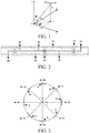
FIG. 1 is a schematic diagram of a definition of a rectangular coordinate system used in an antenna model according to the present invention. -
FIG. 2 is a front view of an omnidirectional subarray unit of an omnidirectional array antenna according to the present invention. -
FIG. 3 is a top view of an omnidirectional array antenna model according to the present invention. -
FIG. 4 is a front view of an omnidirectional array antenna model according to the present invention -
FIG. 5 shows a VSWR curve of a standing wave of an omnidirectional subarray unit according to the present invention. -
FIG. 6 is a 2D directional diagram of an omnidirectional subarray unit according to the present invention at a central frequency point fc = 3.5 GHz. -
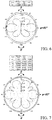
FIG. 7 is a 2D directional diagram of a single formedomnidirectional beam # 1 of an omnidirectional array antenna according to the present invention at fc = 3.5 GHz. -
FIG. 8 is a 2D directional diagram of a single formedomnidirectional beam # 2 of an omnidirectional array antenna according to the present invention at fc = 3.5 GHz. -
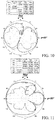
FIG. 9 is a 2D directional diagram of a formed directional narrow double-beam # 3 of an omnidirectional array antenna according to the present invention at fc = 3.5 GHz. -
FIG. 10 is a 2D directional diagram of a formed directional wide double-beam # 4 of an omnidirectional array antenna according to the present invention at fc = 3.5 GHz. -
FIG. 11 is a 2D directional diagram of a formed directional unequal-width double-beam # 6 of an omnidirectional array antenna according to the present invention at fc = 3.5 GHz. -
FIG. 12 is a 2D directional diagram of a formed non-collinear directional double-beam # 5 of an omnidirectional array antenna according to the present invention at fc = 3.5 GHz. -
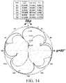
FIG. 13 is a 2D directional diagram of a formed directional triple-beam # 7 of an omnidirectional array antenna according to the present invention at fc = 3.5 GHz. -
FIG. 14 is a 2D directional diagram of a formed directional quadruple-beam # 7 of an omnidirectional array antenna according to the present invention at fc = 3.5 GHz. - The accompanying drawings are included to provide a further description and understanding of the present invention, and constitute a part of this specification. The accompanying drawings together with specific embodiments of the present invention are intended to explain the present invention, but do not constitute any limitation or restriction on the present invention.
- The following provides preferred embodiments of the present invention with reference to the accompanying drawings, to describe the technical solutions of the present invention in detail.
- Herein, two characteristics of ultra wideband and a high gain are emphasized to describe the present invention, and corresponding accompanying drawings are provided to describe the present invention in detail. It should be especially noted that preferred embodiments described herein are only used to describe and explain the present invention and are not used to limit or define the present invention.
- The present invention is intended to provide a design solution of beamforming omnidirectional array antenna for future 5G applications, and to provide an effective reference method for a beamforming design of an H/V single-polarized omnidirectional array antenna or an H/V dual-polarized omnidirectional antenna.
- Referring to
FIGS. 1-4 , a method for constructing the omnidirectional array antenna according to the present invention is shown as follows: - Step I: A spatial rectangle coordinate system is established as shown in
FIG. 1 . - Step II: An omnidirectional subarray unit is constructed: a three-unit omnidirectional subarray unit is constructed in a YOZ plane, including a
dielectric plate 10, twosymmetric arms central feeding point 34, and a short-circuit point 35 at both ends, thecentral feeding point 34 being provided with a bonding pad and a non-metallized via hole, the short-circuit point 35 being provided with a metallized via hole and being printed with parallel two-conductor feeding lines 31, 32, and 33, and all portions being shown inFIG. 2 . - Step III: Eight omnidirectional subarray units form a circular array, and the three-unit omnidirectional subarray unit in step II is rotated and replicated for eight times along an axis z, to form an eight-unit array evenly arranged along a circle with a diameter D = 1 λc, and a circumferential diameter is perpendicular to a
PCB dielectric plate 10 of various omnidirectional subarray units; various subarrays are numbered UC#1-UC#8 (UC, Unit Cell), respectively located at azimuth angles of ϕ = 45°, 90°, 135°, 180°, 225°, 270°, 325°, and 360°, as shown inFIG. 3 andFIG. 4 . - Step IV: An array beam is formed by means of equiamplitude and in-phase or out-phase feeding form eight types of beams, as shown in
FIGS. 7-14 . - The omnidirectional array antenna obtained according to the foregoing construction method includes an antenna array consisting of N omnidirectional subarray units arranged circumferentially, a diameter of the circular array being an integral multiple (that is, D =2·R = m·λc , m being a natural number) of a central wavelength λc, and each of the omnidirectional subarray units including p coaxially-arrayed symmetrical oscillators, and N and p being both natural numbers. In this embodiment, N is 8, and p is 3.
- The coaxially-arrayed symmetric oscillators of the omnidirectional subarray units are half-wave oscillators, or may include half-wave oscillators or oscillators of other wavelengths.
- The symmetric oscillators of the omnidirectional subarray units are coaxially arrayed into a vertically polarized subarray or coplanarly arrayed into a horizontally polarized subarray.
- The N omnidirectional subarray units are vertically arranged at equal intervals, and a circumferential azimuth angle ϕn =2·n·π/N, where n = 1, 2, 3, ..., N.
- The symmetric oscillators of the omnidirectional subarray units are printed on a PCB dielectric plate, the dielectric plate being perpendicular to a diameter of the circular array. In some other implementations, the symmetrical oscillators of the omnidirectional subarray units may also be constructed in a form of a metal tube.
- N array elements are arranged into a uniform circular array (N ≥ 1, N being a natural number), a spacing angle between adjacent array elements is Δϕ=2·π/N, a diameter of the circular array is an integral multiple (that is, D=2·R=m·λc , m being a natural number) of the central wavelength λc. In this embodiment, a number N = 8 = 23 of array elements is selected as a preferred embodiment, each omnidirectional subarray unit including 3 (p = 3) symmetric oscillators.
- The present invention is applicable to the omnidirectional array antenna beamforming method for the foregoing omnidirectional subarray units, various omnidirectional subarray units being stimulated by means of equiamplitude (In = 1; n = 1, 2, 3, ..., N), and in-phase or out-phase stimulation, thereby forming different types of beams.
- Referring to
FIGS. 5-14 , in this embodiment, the different types of beams include eight types of beams in total, such as a singleomnidirectional beam # 1, a singledirectional beam # 2, a directional narrow double-beam # 3, a directional wide double-beam # 4, a non-collinear directional double-beam # 5, a directional unequal-width double-beam # 6, a directional triple-beam # 7, and a directional quadruple-beam # 8. - A forming algorithm of the single
omnidirectional beam # 1 is stimulating various omnidirectional subarray units by means of equiamplitude, and a phase satisfies the following: four odd-numbered array elements are in phase, that is, β1 =β3 =β5 =β7 ; four even-numbered array elements are in phase, that is, β2 =β4 =β6 =β8 ; and the two sets of phases respectively satisfy relations: β1 =β2 +Δβ, Δβ∈[0, π/2]. - A forming algorithm of the single
directional beam # 2 is stimulating various omnidirectional subarray units by means of equiamplitude, and a phase satisfies the following:

- A forming algorithm of a directional double
narrow beam # 3 is stimulating various omnidirectional subarray units by means of equiamplitude, and a phase satisfies the following relations: β1 =β4 =(1/1.75+2·q)·π, β2 =β3 =2·q·π, β5 =β8 =1(1+1/1.75)+2·q]·π, and β6 =β 7=(1+2·q)·π, where q is an integer. - A forming algorithm of the directional wide double-
beam # 4 is stimulating various array elements by means of equiamplitude, and a phase satisfies the following relations: β1 =β2 =β3 =β4 =2·q·π; β5 =β6 =β7 =β8 ==(1+2·q)·π, where q is an integer. - A forming algorithm of the directional unequal-width double-
beam # 5 is stimulating various array elements by means of equiamplitude, and a phase satisfies the following relations: β1 =β3 ={[1-cos(π/4)]+2·q}·π, β2 =2·q·π, β4 =β8 =π, β5 =β7 =[(1-1/4)+2·q]·π, and β6 =[(1-1/6)+ 2·q]·π, where q is an integer. - A forming algorithm of the non-collinear directional double-
beam # 6 is stimulating various array elements by means of equiamplitude, and a phase satisfies the following relations: β1 =β3 =(1/1.75+2·q)·π, β2 =2·q·π, β4 =(1/1.75+1/2+2·q)·π, β5 =[(1+1/1.75+1/2)+ 2·q]·π, β 7=π, and β6 =β8 =[(1+1/1.75)+2·q]·π, where q is an integer. - A forming algorithm of the directional triple-
beam # 7 is stimulating various array elements by means of equiamplitude, and a phase satisfies the following relations: β1 =β3 ={[1-cos(π/4)]+2·q}·π, β2 =2·q·π, β4 =β8 =(1+2·q)·π, β5 =[(1+1/3.5)+ 2·q]·π, β6 =[(1+1/2.875)+ 2·q]·π, and β7 =[(1-1/3.5)+ 2·q]·π, where q is an integer. - A forming algorithm of the directional quadruple-
beam # 8 is stimulating various array elements by means of equiamplitude, and a phase satisfies the following relations: β1 =β4 =β5 =β8 =2·q·π; β2 =β3 =β6 =β7 =(1+2·q)·π, where q is an integer. - According to the omnidirectional array antenna beamforming method proposed in the present invention, 8 (N = 8) array elements are used, and the array elements being composed of 3 (p = 3) meta-symmetric oscillator subarrays, and the following beamforming algorithms are uniquely used to realize eight typical business beams: (1) an omnidirectional beam formed through stimulation by means of equiamplitude and in-phase stimulation, to cover a horizontal periphery; (2) a horizontally directional beam formed through stimulation by means of equiamplitude and out-phase stimulation, to point to an azimuth angle; (3) a horizontally directional narrow double-beam formed through stimulation by means of equiamplitude and out-phase stimulation, the two beams being collinear and having equal widths; (4) a horizontally directional wide double-beam formed through stimulation by means of equiamplitude and out-phase stimulation, the two beams being collinear and having equal widths; (5) a horizontally directional unequal-width double-beam formed through stimulation by means of equiamplitude and out-phase stimulation, the two beams being collinear and having unequal widths; (6) a horizontally directional narrow double-beam formed through stimulation by means of equiamplitude and out-phase stimulation, the two beams having equal widths and being not collinear; (7) a horizontally directional triple-beam formed through stimulation by means of equiamplitude and out-phase stimulation, the three beams having unequal widths and unequal included angles; (8) a horizontally directional narrow quadruple-beam formed through stimulation by means of equiamplitude and out-phase stimulation, the four beams having equal widths and equal included angles. The foregoing eight beams are the most typical and most useful types in future 5G applications. Implementation of multiple MIMO beamforming capabilities means that the omnidirectional array exhibits great potential in 5G applications. |
- For the beamforming implementation effect of the omnidirectional array antenna in the present invention, reference may be made to Table I below, a specific algorithm instance table for the beamforming implementation of the omnidirectional array antenna,
FIGS. 7-14 , and 2D directional diagrams of various beams at fc = 3.5 GHz.

-
FIG. 5 shows a VSWR curve of a standing wave of an omnidirectional subarray unit according to the present invention. It can be seen from the figure that within a frequency band of 3.4-3.6 GHz, the VSWR of the standing wave of the subarray unit ≤ 1.60, with good impedance matching. -
FIG. 6 is a 2D directional diagram of an omnidirectional subarray unit according to the present invention at a central frequency point fc = 3.5 GHz. A solid line represents an H-plane (Theta = 90°, XOY plane), and a dashed line represents an E-plane (Phi = 90°, YOZ plane). A beam width in the E-plane is HPBW = 24.73°, ideal omnidirectional radiation (out-of-roundness being less than 0.24 dB) is conducted on the H-plane, and a gain G = 6.68 dBi. -
FIG. 7 is a 2D directional diagram of a formed singleomnidirectional beam # 1 of an omnidirectional array antenna according to the present invention at fc = 3.5 GHz. A solid line represents an H-plane (Theta = 90°, XOY plane), and a dashed line represents an E-plane (Phi = 90°, YOZ plane). A beam width in the E-plane is HPBW = 20.37°, out-of-roundness of the H-plane is less than 0.24 dB, a gain G = 6.47 dBi, and a radiation feature is almost the same as that of a subarray unit. -
FIG. 8 is a 2D directional diagram of a formed singleomnidirectional beam # 2 of an omnidirectional array antenna according to the present invention at fc = 3.5 GHz. A solid line represents an H-plane (Theta = 90°, XOY plane), and a dashed line represents an E-plane (Phi = 0°, YOZ plane). A main lobe points to a direction of an azimuth angle ϕ = 0°, a beam width in the E/H plane is respectively: HPBW = 23.92° and 40.67°, and a gain G = 13.78 dBi. A sidelobe level (SLL) is lower than that of the main lobe by about 13.78 dB, and a front-to-back ratio (FTBR) is 7.5 dB. -
FIG. 9 is a 2D directional diagram of a formed directional narrow double-beam # 3 of an omnidirectional array antenna according to the present invention at fc = 3.5 GHz. A solid line represents an H-plane (Theta = 90°, XOY plane), and a dashed line represents an E-plane (Phi = 113°, YOZ plane). A main lobe points to a direction of azimuth angles ϕ = 113° and 293°, and an angle between the two main lobes is 180°. A beam width in the E/H plane is respectively: HPBW = 25.18° and 32.68°, and a gain G = 12.33 dBi. A sidelobe level (SLL) is lower than that of the main lobe by about 9 dB, and a deep zero point is formed in a direction orthogonal to a main beam. -
FIG. 10 is a 2D directional diagram of a formed directional wide double-beam # 4 of an omnidirectional array antenna according to the present invention at fc = 3.5 GHz. A solid line represents an H-plane (Theta = 90°, XOY plane), and a dashed line represents an E-plane (Phi = 112°, YOZ plane). A main lobe points to a direction of azimuth angles ϕ = 112° and 292°, and an angle between the two main lobes is 180°. A beam width in the E/H plane is respectively: HPBW = 28.85° and 50.18°, and a gain G = 9.41 dBi, and a deep zero point is formed in a direction orthogonal to a main beam. -
FIG. 11 is a 2D directional diagram of a formed directional unequal-width double-beam # 6 of an omnidirectional array antenna according to the present invention at fc = 3.5 GHz. A solid line represents an H-plane (Theta = 90°, XOY plane), and a dashed line represents an E-plane (Phi = 90°, YOZ plane). A main lobe points to a direction of azimuth angles ϕ = 90° and 270°, and an angle between the two main lobes is 180°. A beam width in the E/H plane is respectively: HPBW = 24.50° and 117.0°, (a wide beam)/31.20° (a narrow beam), a gain G = 9.47 dBi, so that a deep zero point is formed at a location at which a main beam intersects a sub-beam. -
FIG. 12 is a 2D directional diagram of a formed non-collinear directional double-beam # 5 of an omnidirectional array antenna according to the present invention at fc = 3.5 GHz. A solid line represents an H-plane (Theta = 90°, XOY plane), and a dashed line represents an E-plane (Phi = 97°, YOZ plane). A main lobe points to a direction of azimuth angles ϕ = 97° and 309°, and an angle between the two main lobes is 148° (a sharp angle) or 212° (an obtuse angle). A beam width in the E/H plane is respectively: HPBW = 24.60° and 31.20°, and a gain G = 11.96 dBi. Ipsilateral and lateral sidelobe levels (SLL) are respectively lower than that of the main lobe level by about 7 dB and 5.5 dB, and deep zero points are formed in a direction orthogonal to a main beam and at a location at which the lateral sidelobe intersects the main lobe. -
FIG. 13 is a 2D directional diagram of a formed directional triple-beam # 7 of an omnidirectional array antenna according to the present invention at fc = 3.5 GHz. A solid line represents an H-plane (Theta = 90°, XOY plane), and a dashed line represents an E-plane (Phi = 90°, YOZ plane). Three main lobes point to directions of azimuth angles ϕ = 90°, 215°, and 315°, and angles between two adjacent main lobes are respectively 143°, 135° and 100°. A beam width in the E/H plane is respectively: HPBW = 24.5°, 65°/50°/46°, and a gain G = 10.73 dBi. Relatively deeper zero points are formed at a location three beams intersect. -
FIG. 14 is a 2D directional diagram of a formed directional quadruple-beam # 7 of an omnidirectional array antenna according to the present invention at fc = 3.5 GHz. A solid line represents an H-plane (Theta = 90°, XOY plane), and a dashed line represents an E-plane (Phi = 23°/113°, YOZ plane). Four main lobes respectively point to directions of azimuth angles ϕ = 23°, 113°, 203°, and 293°, and an angle between two adjacent main lobes is 90°. A beam width in the E/H plane is respectively: HPBW = 25.13°, 47.24°, and a gain G = 8.81 dBi. Deep zero points are formed at a location four beams intersect. - The above descriptions are merely preferred embodiments of the present invention, but not intended to limit or restrict the present invention. A researched or technician skilled in the art may make various modifications and changes to the present invention. Any modification, equivalent replacement, or improvement made without departing from the spirit and principle of the present invention should fall within the protection scope stated in the present invention.
Claims (17)
- An omnidirectional array antenna, comprising N omnidirectional subarray units that are circumferentially arranged to form a circular array, a diameter of the circular array being an integral multiple of a central wavelength λc, and each of the omnidirectional subarray units comprising p coaxially-arrayed symmetrical oscillators, wherein N and p are both natural numbers.
- The omnidirectional array antenna according to claim 1, wherein the coaxially-arrayed symmetrical oscillators of the omnidirectional subarray units are half-wave oscillators.
- The omnidirectional array antenna according to claim 2, wherein the symmetric oscillators of the omnidirectional subarray units are coaxially arrayed into a vertically polarized subarray or coplanarly arrayed into a horizontally polarized subarray.
- The omnidirectional array antenna according to claim 1, wherein the N omnidirectional subarray units are vertically arranged at equal intervals, a circumferential azimuth angle ϕn =2·n·π/N, wherein n = 1, 2, 3, ... , N.
- The omnidirectional array antenna according to claim 1, wherein the symmetric oscillators of the omnidirectional subarray units are printed on a PCB dielectric plate, the dielectric plate being perpendicular to a diameter of the circular array.
- The omnidirectional array antenna according to claim 1, wherein the symmetrical oscillators of the omnidirectional subarray units are constructed in a form of a metal tube.
- The omnidirectional array antenna according to claim 1, wherein the omnidirectional subarray units have different types of beams, comprising at least one of a single omnidirectional beam, a single directional beam, a directional narrow double-beam, a directional wide double-beam, a non-collinear directional double-beam, a directional unequal-width double-beam, a directional triple-beam, and a directional quadruple-beam.
- An omnidirectional array antenna beamforming method, wherein the omnidirectional array antenna beamforming method is applied to the omnidirectional array antenna according to any of claims 1 to 7, and various omnidirectional subarray units are stimulated by means of equiamplitude, in-phase or out-phase stimulation, thereby forming different types of beams.
- The omnidirectional array antenna beamforming method according to claim 8, wherein the different types of beams comprise at least one of a single omnidirectional beam, a single directional beam, a directional narrow double-beam, a directional wide double-beam, a non-collinear directional double-beam, a directional unequal-width double-beam, a directional triple-beam, and a directional quadruple-beam.
- The omnidirectional array antenna beamforming method according to claim 9, wherein the omnidirectional array antenna comprises eight omnidirectional subarray units, a forming algorithm of the single omnidirectional beam being stimulating various omnidirectional subarray units by means of equiamplitude, a phase satisfying the following: four odd-numbered array elements being of a same phase, that is, β1 =β3 =β5 =β7 ; four even-numbered array elements being of a same phase, that is, β2 =β4 =β6 =β8 ; and the two sets of phases respectively satisfying relations: β1 =β2 +Δβ and Δβ∈[0, π/2].
- The omnidirectional array antenna beamforming method according to claim 9, wherein the omnidirectional array antenna comprises eight omnidirectional subarray units, a forming algorithm of the single directional beam being stimulating various omnidirectional subarray units by means of equiamplitude, and a phase satisfying the following:

- The omnidirectional array antenna beamforming method according to claim 9, wherein the omnidirectional array antenna comprises eight omnidirectional subarray units, a forming algorithm of the directional narrow double-beam being stimulating various omnidirectional subarray units by means of equiamplitude, a phase satisfying the following: β1 =β4 =(1/1.75+2·q)·π, β2 =β3 =2·q·π, β5 =β8 =[(1+1/1.75)+2·q]·π, and β6 =β7 =(1+2·q)·π, wherein q is an integer.
- The omnidirectional array antenna beamforming method according to claim 9, wherein the omnidirectional array antenna comprises eight omnidirectional subarray units, a forming algorithm of the directional wide double-beam being stimulating various array elements by means of equiamplitude, and a phase satisfying the following: β1 =β2 =β3 =β4 =2·q·π; β5 =β6 =β7 =β8 ==(1+2·q)·π, wherein q is an integer.
- The omnidirectional array antenna beamforming method according to claim 9, wherein the omnidirectional array antenna comprises eight omnidirectional subarray units, a forming algorithm of the directional unequal-width double-beam being stimulating various array elements by means of equiamplitude, the phase satisfying the following: β1 =β3 ={[1-cos(π/4)]+2·q}·π, β2 =2·q·π, β4 =β8 =π, β5 =β7 =[(1-1/4)+2·q]·π, and β6 =[(1-1/6)+ 2·q]·π, wherein q is an integer.
- The omnidirectional array antenna beamforming method according to claim 9, wherein the omnidirectional array antenna comprises eight omnidirectional subarray units, a forming algorithm of the non-collinear directional double-beam being stimulating various array elements by means of equiamplitude, a phase satisfying the following: β1 =β3 =(1/1.75+2·q)·π, β2 =2·q·π, β4 =(1/1.75+1/2+2·q)·π, β5 =[(1+1/1.75+1/2)+ 2·q]·π, β7 =π, and β6 =β8 =[(1+1/1.75)+ 2·q]·π, wherein q is an integer.
- The omnidirectional array antenna beamforming method according to claim 9, wherein the omnidirectional array antenna comprises eight omnidirectional subarray units, a forming algorithm of the directional triple-beam being stimulating various array elements by means of equiamplitude, a phase satisfying the following: β1 =β3 ={[1-cos(π/4)]+ 2·q} ·π, β2 =2·q·π, β4 =β8 =(1+2·q)·π, β5 =[(1+1/3.5)+ 2·q]·π, β6 =[(1+1/2.875)+2·q]·π, and β 7=[(1-1/3.5)+ 2·q]·π, wherein q is an integer.
- The omnidirectional array antenna beamforming method according to claim 9, wherein the omnidirectional array antenna comprises eight omnidirectional subarray units, a forming algorithm of the directional quadruple-beam being stimulating various array elements, a phase satisfying the following: β1 =β4 =β5 =β8 =2·q·π and β2 =β3 =β6 =β7 =(1+2·q)·π, wherein q is an integer.
Applications Claiming Priority (1)
| Application Number | Priority Date | Filing Date | Title |
|---|---|---|---|
| PCT/CN2017/113091 WO2019100376A1 (en) | 2017-11-27 | 2017-11-27 | Omnidirectional array antenna and beamforming method therefor |
Publications (2)
| Publication Number | Publication Date |
|---|---|
| EP3720008A1 true EP3720008A1 (en) | 2020-10-07 |
| EP3720008A4 EP3720008A4 (en) | 2021-07-07 |
Family
ID=66630879
Family Applications (1)
| Application Number | Title | Priority Date | Filing Date |
|---|---|---|---|
| EP17932945.3A Pending EP3720008A4 (en) | 2017-11-27 | 2017-11-27 | Omnidirectional array antenna and beamforming method therefor |
Country Status (3)
| Country | Link |
|---|---|
| US (1) | US11233335B2 (en) |
| EP (1) | EP3720008A4 (en) |
| WO (1) | WO2019100376A1 (en) |
Families Citing this family (3)
| Publication number | Priority date | Publication date | Assignee | Title |
|---|---|---|---|---|
| GB201803433D0 (en) * | 2018-03-02 | 2018-04-18 | Secr Defence | Dual polarised antenna |
| CN111988075B (en) * | 2020-07-10 | 2021-05-28 | 中国人民解放军战略支援部队航天工程大学 | Antenna array signal synthesis method based on maximum correlation signal-to-noise ratio criterion |
| CN112054829B (en) * | 2020-07-10 | 2021-04-23 | 中国人民解放军战略支援部队航天工程大学 | Antenna array signal synthesis method with fixed phase center characteristic |
Family Cites Families (13)
| Publication number | Priority date | Publication date | Assignee | Title |
|---|---|---|---|---|
| US4973971A (en) * | 1989-12-18 | 1990-11-27 | Allied-Signal Inc. | Broadband circular phased array antenna |
| CN2293901Y (en) * | 1997-03-13 | 1998-10-07 | 北京信威通信技术有限公司 | Ring shape intelligent antenna array for radio communication system |
| GB2376568B (en) * | 2001-06-12 | 2005-06-01 | Mobisphere Ltd | Improvements in or relating to smart antenna arrays |
| GB2376567B (en) * | 2001-06-12 | 2005-07-20 | Mobisphere Ltd | Improvements in or relating to smart antenna arrays |
| US8344943B2 (en) * | 2008-07-28 | 2013-01-01 | Physical Domains, LLC | Low-profile omnidirectional retrodirective antennas |
| US20130321207A1 (en) * | 2012-05-31 | 2013-12-05 | Alcatel-Lucent Usa Inc. | Transforming precoded signals for wireless communication |
| JP2014143591A (en) * | 2013-01-24 | 2014-08-07 | Nippon Dengyo Kosaku Co Ltd | Array antenna |
| US9729213B2 (en) * | 2014-01-30 | 2017-08-08 | Xirrus, Inc. | MIMO antenna system |
| EP3254134A4 (en) * | 2015-02-04 | 2018-10-17 | Artsys360 Ltd. | Multimodal radar system |
| CN107275800A (en) * | 2017-05-16 | 2017-10-20 | 南京航空航天大学 | A kind of antenna structure of extensive MIMO array |
| US10505609B2 (en) * | 2017-06-14 | 2019-12-10 | Commscope Technologies Llc | Small cell beam-forming antennas |
| CN207475549U (en) * | 2017-11-27 | 2018-06-08 | 广东通宇通讯股份有限公司 | omni-directional array antenna |
| CN107863996B (en) * | 2017-11-27 | 2020-10-16 | 广东通宇通讯股份有限公司 | Omnidirectional array antenna and beam forming method thereof |
-
2017
- 2017-11-27 EP EP17932945.3A patent/EP3720008A4/en active Pending
- 2017-11-27 US US16/651,505 patent/US11233335B2/en active Active
- 2017-11-27 WO PCT/CN2017/113091 patent/WO2019100376A1/en unknown
Also Published As
| Publication number | Publication date |
|---|---|
| EP3720008A4 (en) | 2021-07-07 |
| US11233335B2 (en) | 2022-01-25 |
| WO2019100376A1 (en) | 2019-05-31 |
| US20200303831A1 (en) | 2020-09-24 |
Similar Documents
| Publication | Publication Date | Title |
|---|---|---|
| Tang et al. | Pattern-reconfigurable, flexible, wideband, directive, electrically small near-field resonant parasitic antenna | |
| Tang et al. | A study of 28 GHz, planar, multilayered, electrically small, broadside radiating, Huygens source antennas | |
| CN107863996B (en) | Omnidirectional array antenna and beam forming method thereof | |
| US20130106667A1 (en) | Simultaneous transmit and receive antenna system | |
| CN107078383B (en) | Antenna device for base station antenna system | |
| US20180241135A1 (en) | 27-28.5 GHz Ka BAND PHASED ARRAY FAN BEAM ANTENNAS AND METHODS | |
| CN102570058A (en) | Compound multi-antenna system and wireless communication device thereof | |
| CA2511684A1 (en) | Null-fill antenna, omni antenna, and radio communication equipment | |
| CN107910648B (en) | Low-profile dual-band omnidirectional circularly polarized antenna | |
| US11233335B2 (en) | Omnidirectional array antenna and beamforming method therefor | |
| Sun et al. | A compact planar omnidirectional MIMO array antenna with pattern phase diversity using folded dipole element | |
| CN105048079B (en) | A kind of omni-directional circular polarization plane antenna | |
| CN207475549U (en) | omni-directional array antenna | |
| US11769952B2 (en) | Antenna element and electronic device | |
| US20130201066A1 (en) | Wireless communications device having loop antenna with four spaced apart coupling points and reflector and associated methods | |
| KR20170096196A (en) | Cellular array with adjustable spotlight beam | |
| JPWO2018216438A1 (en) | Wireless communication device and antenna device | |
| CN109301505A (en) | A kind of ultra wide band OAM vortex electromagnetic antenna | |
| CN204407491U (en) | Antenna, antenna system and communication equipment | |
| CN209001147U (en) | A kind of ultra wide band OAM vortex electromagnetic antenna | |
| Chaudhary et al. | 360° angular coverage pattern and polarization diversities wideband circularly polarized multiple input multiple output antennas | |
| Ma et al. | Dual-polarized turning torso antenna array for massive MIMO systems | |
| Feng et al. | A printed dual-wideband magneto-electric dipole antenna for WWAN/LTE applications | |
| Aghdam et al. | The sinuous antenna-A dual polarized feed for reflector-based searching systems | |
| US11189939B2 (en) | Dual-polarized wide-bandwidth antenna |
Legal Events
| Date | Code | Title | Description |
|---|---|---|---|
| STAA | Information on the status of an ep patent application or granted ep patent |
Free format text: STATUS: THE INTERNATIONAL PUBLICATION HAS BEEN MADE |
|
| PUAI | Public reference made under article 153(3) epc to a published international application that has entered the european phase |
Free format text: ORIGINAL CODE: 0009012 |
|
| STAA | Information on the status of an ep patent application or granted ep patent |
Free format text: STATUS: REQUEST FOR EXAMINATION WAS MADE |
|
| 17P | Request for examination filed |
Effective date: 20200326 |
|
| AK | Designated contracting states |
Kind code of ref document: A1 Designated state(s): AL AT BE BG CH CY CZ DE DK EE ES FI FR GB GR HR HU IE IS IT LI LT LU LV MC MK MT NL NO PL PT RO RS SE SI SK SM TR |
|
| AX | Request for extension of the european patent |
Extension state: BA ME |
|
| DAV | Request for validation of the european patent (deleted) | ||
| DAX | Request for extension of the european patent (deleted) | ||
| A4 | Supplementary search report drawn up and despatched |
Effective date: 20210604 |
|
| RIC1 | Information provided on ipc code assigned before grant |
Ipc: H04B 7/0413 20170101AFI20210528BHEP Ipc: H01Q 3/26 20060101ALI20210528BHEP Ipc: H01Q 21/20 20060101ALI20210528BHEP |