EP3719975A1 - Machine électrique - Google Patents
Machine électrique Download PDFInfo
- Publication number
- EP3719975A1 EP3719975A1 EP19167289.8A EP19167289A EP3719975A1 EP 3719975 A1 EP3719975 A1 EP 3719975A1 EP 19167289 A EP19167289 A EP 19167289A EP 3719975 A1 EP3719975 A1 EP 3719975A1
- Authority
- EP
- European Patent Office
- Prior art keywords
- electrical machine
- heat sink
- machine according
- stator
- electronic component
- Prior art date
- Legal status (The legal status is an assumption and is not a legal conclusion. Google has not performed a legal analysis and makes no representation as to the accuracy of the status listed.)
- Withdrawn
Links
Images


Classifications
-
- H—ELECTRICITY
- H02—GENERATION; CONVERSION OR DISTRIBUTION OF ELECTRIC POWER
- H02K—DYNAMO-ELECTRIC MACHINES
- H02K11/00—Structural association of dynamo-electric machines with electric components or with devices for shielding, monitoring or protection
- H02K11/30—Structural association with control circuits or drive circuits
- H02K11/33—Drive circuits, e.g. power electronics
-
- H—ELECTRICITY
- H02—GENERATION; CONVERSION OR DISTRIBUTION OF ELECTRIC POWER
- H02K—DYNAMO-ELECTRIC MACHINES
- H02K3/00—Details of windings
- H02K3/04—Windings characterised by the conductor shape, form or construction, e.g. with bar conductors
- H02K3/12—Windings characterised by the conductor shape, form or construction, e.g. with bar conductors arranged in slots
-
- H—ELECTRICITY
- H02—GENERATION; CONVERSION OR DISTRIBUTION OF ELECTRIC POWER
- H02K—DYNAMO-ELECTRIC MACHINES
- H02K3/00—Details of windings
- H02K3/04—Windings characterised by the conductor shape, form or construction, e.g. with bar conductors
- H02K3/28—Layout of windings or of connections between windings
-
- H—ELECTRICITY
- H02—GENERATION; CONVERSION OR DISTRIBUTION OF ELECTRIC POWER
- H02K—DYNAMO-ELECTRIC MACHINES
- H02K9/00—Arrangements for cooling or ventilating
- H02K9/22—Arrangements for cooling or ventilating by solid heat conducting material embedded in, or arranged in contact with, the stator or rotor, e.g. heat bridges
- H02K9/227—Heat sinks
-
- H—ELECTRICITY
- H02—GENERATION; CONVERSION OR DISTRIBUTION OF ELECTRIC POWER
- H02K—DYNAMO-ELECTRIC MACHINES
- H02K15/00—Methods or apparatus specially adapted for manufacturing, assembling, maintaining or repairing of dynamo-electric machines
- H02K15/08—Forming windings by laying conductors into or around core parts
- H02K15/085—Forming windings by laying conductors into or around core parts by laying conductors into slotted stators
-
- H—ELECTRICITY
- H02—GENERATION; CONVERSION OR DISTRIBUTION OF ELECTRIC POWER
- H02K—DYNAMO-ELECTRIC MACHINES
- H02K2203/00—Specific aspects not provided for in the other groups of this subclass relating to the windings
- H02K2203/03—Machines characterised by the wiring boards, i.e. printed circuit boards or similar structures for connecting the winding terminations
-
- H—ELECTRICITY
- H02—GENERATION; CONVERSION OR DISTRIBUTION OF ELECTRIC POWER
- H02K—DYNAMO-ELECTRIC MACHINES
- H02K2203/00—Specific aspects not provided for in the other groups of this subclass relating to the windings
- H02K2203/09—Machines characterised by wiring elements other than wires, e.g. bus rings, for connecting the winding terminations
Definitions
- the present invention relates to an electrical machine with a stator.
- the stator has electrical windings which are connected to a power system, which is often multi-phase. For applications with more than two coils per pole per phase, mostly distributed windings are used.
- the main advantage of the distributed windings is that the magnetomotive force in the air gap between the stator and a rotor of the machine that is movably mounted to the stator has less harmonic content, i.e. a smaller proportion of undesired harmonics of the magnetomotive force. This results in a high efficiency of the machine, which can be operated as a motor or generator, with low rotor losses, low noise and few vibration problems.
- a disadvantage of the distributed winding is the complex production.
- the DE 10 2014 113 489 A1 suggest, in a machine with a stator comprising a plurality of slots, which are formed between adjacent teeth of the stator and serve to accommodate a stator winding, to insert a conductor section of the stator winding into each slot.
- the conductor sections of at least one pole pair are short-circuited to one another on a first side of the stator.
- the free ends of the conductor sections are connected to a connection of a power supply unit.
- the power supply unit comprises two electrical conductors.
- active cooling is required provided by providing an annular cooling duct for guiding a fluid on which the power electronic components are arranged. It is provided that the cooling duct is provided in or between the two conductors arranged in a ring. This results in a complex production.
- an electrical machine with a stator includes a plurality of grooves formed between adjacent teeth of the stator.
- the slots are used to accommodate a stator winding.
- a conductor section of the stator winding is inserted into each slot.
- the conductor sections of at least one pole pair are short-circuited to one another on a first side of the stator.
- On a second side of the stator opposite the first side the free ends of the conductor sections are connected to a connection of a power supply unit.
- the power supply unit comprises at least two conductors that are electrically connected to at least one power electronic component.
- the power electronic component is assigned to one or more conductor sections.
- the at least one power electronic component is arranged on a heat sink, the heat sink being essentially disk-shaped and covering the second side of the stator over a large area.
- a large-area heat sink can be provided, which the second side of the stator covered, ie arranged on the end face of the stator, and serves as a carrier for the power electronic component. This ensures simplified and efficient cooling of the at least one power electronic component, with the machine being able to be manufactured with little manufacturing effort.
- the initially mentioned windings on the stator side are replaced in the proposed electrical machine by a single bar winding, which is simplified to the effect that it has conductor sections per slot and thus the conductor sections can, for example, be designed essentially straight in the axial direction.
- high currents can be used with low voltage in order to achieve a magnetomotive force of the same order of magnitude as in conventional machines with distributed winding.
- the integration of the power electronics, which comprise the at least one power electronic component, can be implemented in a simple manner by the arrangement on the disk-shaped and therefore flat heat sink, which in particular results in a particularly compact design of the electrical machine.
- An essentially disk-shaped design of the cooling body should be understood to mean not only circular but also polygonal edge contours.
- the edge contour can thus have a number of corners, so that the edge contour has a square, a pentagon, a hexagon, etc. In general, the number of corners is greater than or equal to four.
- the heat sink is preferably made of a non-magnetic material.
- the material used for the heat sink is preferably not electrically conductive.
- each power electronic component makes contact with a conductor section (designed as a single rod).
- One power electronic component is used for each for the electrical supply of one conductor section each.
- a plurality of electronic power components can also be provided, which are distributed along the circumference of the stator on the heat sink.
- the cooling body can expediently comprise at least one fluid channel for guiding a fluid.
- the at least one fluid channel is arranged in the cooling body in such a way that, in particular, the heat generated by the power electronic component can be dissipated well.
- the at least two conductors are annular. This makes it possible, especially when a large number of power electronic components are provided, to apply respective voltage potentials to them in a simple manner.
- At least one of the at least two conductors is arranged on the heat sink. If the heat sink is made of an insulating material, no separate insulation measures need to be provided.
- a new embodiment provides that at least one of the at least two conductors is arranged together with the at least one power electronic component on a first side of the heat sink.
- at least one of the at least two conductors can be arranged on a second side of the heat sink opposite the first side. Arrangements are therefore possible in which the at least two conductors are arranged on the side of the cooling body facing the stator.
- Another embodiment enables a variant in which the at least two conductors are arranged on the side of the cooling body facing away from the stator.
- a variant is also possible in which one of the conductors is arranged on the side of the cooling body facing the stator and the other of the two conductors is arranged on the side of the cooling body facing away from the stator. Which variant to prefer can be made dependent in particular on the available space.
- the heat sink forms one of the at least two conductors. As a result, a larger area proportion can be provided for the at least one power electronic component on the area of the heat sink. It goes without saying that in this case the heat sink must be implemented in an electrically isolated manner from the components attached to it.
- a power electronic component comprises a single or multi-layer printed circuit board (in particular in the form of a metal substrate printed circuit board) with at least one semiconductor switch and an optional driver circuit.
- the power electronic component can include further electronic components, such as at least one capacitor.
- the driver circuit and the further electronic components can also be arranged on one or more other printed circuit boards.
- At least one of the at least two conductors is arranged on the circuit board.
- the circuit board can then be used as an insulating body for the heat sink.
- the at least one semiconductor circuit and the optional driver circuit are arranged on and / or in the circuit board.
- the outer surfaces can be used over a large area for contacting the at least two conductors. This allows small specific currents per area to be achieved.
- the at least one semiconductor switch and / or the optional driver circuit are designed as a surface-mountable component. This allows the power electronic component to be provided with compact dimensions. In particular, no discrete power electronic modules are required, which require a relatively large amount of space.
- the printed circuit board forms at least part of the heat sink.
- the circuit board can be provided with at least one cooling groove open on one side to form the at least one fluid channel, the circuit board being connected to a counter plate on the side having the at least one cooling groove open on one side.
- the counter plate can optionally have cooling grooves which are open on one side and which are arranged to correspond to the cooling grooves of the circuit board.
- conductor sections are extended by an associated recess in the heat sink and in the circuit board in order to be electrically connected to the at least one power electronic component on the side of the heat sink facing away from the stator.
- the conductor sections can be connected to the at least one power electronic component through a, in particular, central, inner hole in the cooling body and / or outside the outer circumference of the cooling body via respective connecting pieces.
- the heat sink has a plurality of segments.
- the number of segments corresponds in particular to the number of phases. This enables particularly effective cooling of the power electronics to be provided.
- a respective power electronic component is designed to control one or more phases.
- One of the two, in particular ring-shaped, conductors can implement a positive electrical DC voltage supply.
- Another of the two, in particular ring-shaped, conductors can ensure a negative electrical DC voltage supply. This can be understood as a DC bus. Is e.g. If a third conductor is provided, it can have an intermediate potential.
- the semiconductor switches of a respective power electronic component are connected in particular to form a half bridge. If the electronic power component optionally has a capacitor, this can be designed as an intermediate circuit capacitor or part of a distributed intermediate circuit or a distributed intermediate circuit capacitance. A series and / or parallel connection of several capacitors with an intervening support matrix made of conductive and non-conductive elements can be provided.
- the power supply unit can be designed to supply one conductor section each with its own electrical phase by means of the respective power electronic component.
- the proposed design of the electrical machine has particular advantages from the point of view of electromagnetic compatibility, since no alternating current lines affected by harmonics have to be laid. There is also no need for a separate converter housing. No cables are necessary between separate power electronics and the actual electrical machine, as the power electronics is placed instead of the winding head present in conventional machines.
- the number of phases can be, for example, three, four, five or at least ten.
- the conductor sections can be straight.
- the conductor sections can for example be aluminum rods, copper rods or bronze rods or alloys thereof.
- FIG. 1 illustrate different variants of the arrangement of power electronics and a heat sink for an electrical machine that is known in principle, as defined in the introduction to the description.
- an electrical machine the basic principle, for example from the DE 10 2014 113 489 A1 is known includes a stator.
- the stator has grooves which are distributed along its circumference and extend in a straight line in an axial direction of the stator.
- In each slot there is a conductor section 20 ( Figures 2 , 9 , 10 and 12 ) brought in.
- the conductor sections of at least one pole pair are, for example, short-circuited with one another in a short-circuit ring on a first side.
- Each conductor section 20 can be assigned a power electronic component 1, as will be described in more detail below, which is arranged on an essentially disk-shaped and here exemplarily circular cooling body on a second side of the stator opposite the first side. From this second side of the stator there is also the connection to a power supply unit which, for example, comprises two, preferably at least partially ring-shaped, conductors 17, 18 which are electrically connected to the number of power electronic components 1 are connected.
- a power supply unit which, for example, comprises two, preferably at least partially ring-shaped, conductors 17, 18 which are electrically connected to the number of power electronic components 1 are connected.
- Each electronic power component 1 is constructed as a module and comprises at least one half bridge, as will be explained in more detail later.
- Fig. 1 shows a plan view of a disk-shaped heat sink 10, which covers the second side of the stator over a large area.
- the term "large area” is to be understood here as meaning that the area occupied by the heat sink 10 corresponds approximately to the front surface of the stator on the second side, on which the conductor sections are guided out of the grooves essentially in a straight line in the axial direction (in Fig. 1 not shown).
- the conductor bars penetrate a bearing plate (not shown).
- the disk-shaped heat sink 10 has, for example, a central recess 13, which is referred to below as an inner hole.
- a number of power electronic modules 1 are applied to the first side 11 of the heat sink facing away from the stator.
- the number of power electronic components 1, which are designed in module form, can be 1 or more, the number depending on the number of conductor sections and the phase to be formed and on the topology of the output stage.
- six power electronic components 1 can be arranged adjacent to one another over the entire circumference of the disk-shaped heat sink 10, for example.
- only one power electronic component 1 is shown, the structure of which is basically identical.
- the electronic component 1 comprises a first semiconductor switch 2, a second semiconductor switch 3, an optional driver circuit and an optional electronic component 5, for example a capacitor.
- the semiconductor switches are in particular power semiconductors, for example IGBTs, MOSFETs, JFETs and the like. Depending on the interconnection, the electronic component 1 can additionally include diodes (not shown).
- the semiconductor switches 2, 3 are for example as Half bridge connected.
- the capacitor 5 can represent, for example, an intermediate circuit capacitor of the half bridge.
- the semiconductor switches 2, 3, the optional driver circuit 4 and the electronic component 5 are arranged on a circuit board 6, which consists of a carrier plate and a circuit structure.
- a circuit board 6 which consists of a carrier plate and a circuit structure.
- the circuit structure is shown in Fig. 1 not shown.
- the power electronic component 1 is mechanically connected to the heat sink 10 via its printed circuit board 6. Via the mechanical fastening, which in the exemplary embodiment shown here is carried out via a screw 7, an electronic contact is made simultaneously with a conductor section 20 assigned to the power electronic component 1 (see FIG Fig. 2 ).
- the conductor section 20 is designed as a single rod. Although in the Figs. 1 and 2 If only a single conductor section 20 is shown, the power electronic component 1 can be mechanically and electrically connected to a plurality of conductor sections 20 in the construction described below.
- the screw 7 engages through a recess 9 in the circuit board 6 and a recess 15 arranged concentrically in the axial direction in the cooling body 10 in a sleeve 21 arranged in the recess 15.
- the sleeve 21 can have an internal thread 22 for mechanical connection to the screw 7.
- An electrical connection to the conductor section 20 takes place via the sleeve 21, whereby the connection between the sleeve 21 and the conductor section 20 can be realized by welding, pressure, screwing or a flexible conductor and the like.
- the conductor section 20 can also have a threaded hole with an internal thread, so that the additional sleeve 21 can be omitted.
- the conductor section 20 can also be formed by the recess 9 and the recess 15 protrude and have an external thread at its end. A nut can then be screwed onto this, which takes over a mechanical connection between component 1 and conductor section 20.
- a washer 8 and / or a contact washer can expediently be provided which distributes the force applied by the screw head of the screw 7 over a large area on the circuit board 6.
- the cooling body 10 comprises at least one fluid channel 14 for guiding a cooling fluid, for example (deionized) water and the like.
- a cooling fluid for example (deionized) water and the like.
- the fluid channel 14 runs in the radial direction in the illustration shown, the fluid channel 14 (or the fluid channels) can also run in the axial direction or in a meandering manner. Combinations of these are also possible. Flanges as inlet and outlet for the cooling fluid are not shown.
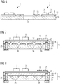
- Fig. 3 shows a second embodiment in a schematic cross-sectional representation.
- the heat sink 10 is again shown, on the first side 11 of which, in the illustration shown, a power electronic component 1 and 1 ′ is applied on both sides of the inner hole 13.
- a power electronic component 1 and 1 ′ is applied on both sides of the inner hole 13.
- the heat sink 10 is provided with respective fluid channels 14 (running in the radial direction, for example).
- the already mentioned conductors 17 and 18 are applied, for example, adjacent to the inner hole 13 as ring-shaped and concentrically arranged metal surfaces.
- the semiconductor switches 2, 3 and 2 ', 3' can be seen.
- the electrical contacting of the (not shown) Conductor sections 20 are made by means of L-shaped connecting pieces 23, with a leg labeled 23A, 23A ', for example by screwing, making contact with a circuit structure of the power electronic component 1, 1'.
- a leg 23B, 23B 'extending in the axial direction of the rotor (which extends perpendicular to the surfaces of the cooling body 10 and the printed circuit boards 6, 6' of the components 1, 1 ') is used for electrical contact with the assigned conductor sections 20, not shown here It can be fastened by welding, screwing or pressing.
- the ring-shaped conductors 17, 18 form a DC bus, wherein, for example, the conductor 17 implements a positive electrical DC voltage and the conductor 18 implements a negative electrical DC voltage supply.
- FIG. 4 The configuration example shown differs from that in Fig. 3 in that only the conductor 17 is arranged on the circuit boards 6, 6 '.
- the heat sink 10 forms the second conductor 18 and implements a negative electrical DC voltage supply.
- it is necessary that the heat sink 18 is separated at least in sections from the power electronic components 1, 1 ′ by means of an electrical insulation material. This can be implemented, for example, by the carrier plates of the printed circuit boards 6, 6 'or a separately implemented insulation layer.
- FIG. 5 shows a slightly modified design variant in which the rotor faces the second side 12 of the cooling body 10.
- the components of the power electronics ie the power electronics components 1, 1 ', face away from the rotor.
- the conductor sections 20 have the sections 23B, 23B 'in the direction of the stator and are optionally (as in Fig. 5 shown) on the outer circumference of the heat sink and / or passed through the inner bore 13.
- the sections 23B, 23B ' can also be guided through slots or dedicated recesses (not shown).
- the inner bore 13 could then be omitted. This depends on where the conductors 17, 18 required for the DC voltage supply are arranged. Since this in the embodiment of Fig. 5 are arranged concentrically around the inner hole and adjacent to the inner hole 13, the legs 23B, 23B 'lead past the outer circumference. However, this could also be reversed.
- Fig. 6 shows an embodiment in which the conductors 17, 18 are not applied to the carrier of the respective power electronic components 1, 1 ', but instead directly on the heat sink 10.
- the heat sink 10 is to be made from an electrically insulating material or an insulation layer between the conductors 17, 18 and in the heat sink 10 to be provided.
- the conductors 17, 18 could be arranged one above the other, insulated from one another.
- the conductor stack could be arranged directly on the heat sink 10 or the circuit board 6.
- FIGS. 7 and 8 show exemplary embodiments in which the printed circuit board 6 is part of the heat sink 10.
- the already mentioned carrier plate 6A of the printed circuit board 6 a number of cooling grooves 16 open on one side.
- a counter plate 24, which is screwed to the carrier plate 6A of the circuit board 6, has a corresponding number of cooling grooves 26 open on one side.
- the connection of the carrier plate 6A and counter plate 25 takes place, for example, by means of a number of screws 25.
- the mechanical connection of carrier plate 6A and counter plate 24 can also be done in other ways, for example gluing, welding, riveting, form-fitting elements, etc.
- the circuit board 6 comprises an insulation layer 6B and a conductor structure applied to it.
- the semiconductor switches 2, 3 and the two conductors 17, 18 for the DC voltage supply are then arranged on the conductor track structure 6C.
- the carrier plate 6A, the insulator 6B and the conductor track structure 6C together form the already mentioned circuit board 6.
- the embodiment shown has only the counter plate 24 on one side open cooling grooves 26. In the exemplary embodiment, these are rectangular. Likewise, only the carrier plate 6A could have cooling grooves open on one side, while the counter plate 24 does not include any cooling grooves.
- the cross-sectional shape of the cooling grooves can be any. Any combination of different cross-sections of cooling grooves can also be provided in one embodiment. Furthermore, only cooling grooves can be provided in sections in the carrier plate 6A and only cooling grooves in the counter plate 24 at other sections.
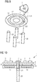
- Fig. 9 shows an exploded perspective view without a heat sink, in which the conductors 17, 18 are arranged below the power electronic components 1. This can best be seen in the associated cross-sectional view of Fig. 10 emerged.
- the semiconductor switches 2, 3, the optional driver circuit 4 and the electronic component 5 are applied to the circuit board 6 of the electronic power component.
- the two conductors 17, 18 are arranged on the opposite side of the circuit board.
- a connection between the printed circuit board 6 of the component 1 takes place merely as an example and the heat sink 10 by a screw connection (not shown) provided between the conductors 17, 18.
- the conductors 17, 18 can have respective recesses 17A and 18A in the area of the screw connection (see FIG Fig. 9 ).
- the screw connection is otherwise as in connection with Fig. 2 described.
- the contacting of the conductor section 20 takes place only by way of example via the sleeve 21 already described, which enables the screw connection.
- the sleeve 21 is supported on the printed circuit board 6 from below.
- the connection between the conductor section 20 and the sleeve 21 can be made by screwing, welding, pressing, soldering or pressure.
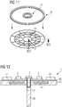
- Fig. 11 shows an embodiment in which the components of the power electronic component are arranged between the concentrically arranged ring-shaped conductors 17, 18, the conductors 17, 18 being arranged on the conductor structure 6C of the circuit board 6 ( Fig. 12 ).
- the conductors 17, 18 and the electronic components of the electronic power component 1 come to lie approximately in a plane which runs perpendicular to the axial direction of the stator.
- the connection between the power electronic component, ie its printed circuit board 6 and the heat sink 10 and the conductor sections 20 arranged behind it, takes place as in connection with Fig. 2 and 10 described.
- Fig. 13 shows an embodiment in which the conductors 17, 18 are not formed in the shape of a ring, but rather are routed as conductor run sections from one power electronic component 1 to the adjacent power electronic component 1 '. This provides a larger area for applying electronic components to the circuit boards 6 of the components 1, 1 '.
- Fig. 14 shows an embodiment in which the semiconductor switches 2, 3 and the optional driver circuit 4 in Inside a multilayer circuit board 6 are arranged. This makes it possible to apply the conductors 17, 18, 23 over a large area on the two opposite surfaces.
- FIG. 15 The embodiment shown are applied to a lower side in the plane of the sheet of the conductor 17 and a further conductor 19, for example an AC voltage conductor.
- the conductor 18 is arranged on the upper side of the printed circuit board 6 in the plane of the sheet.
- the heat sink 10 already described is in turn arranged on the conductor 18.
- the semiconductor switches 2, 3 and the optional driver circuit 4 can be provided with a heat sink on both sides.
- the power electronic component 1 with the electronic components can be applied to the heat sink 10 first.
- the semiconductor switches are in particular power semiconductors. All transistor variants can be used, in particular IGBTs, MOSFETs, JFETs, etc.
Priority Applications (5)
| Application Number | Priority Date | Filing Date | Title |
|---|---|---|---|
| EP19167289.8A EP3719975A1 (fr) | 2019-04-04 | 2019-04-04 | Machine électrique |
| PCT/EP2020/054987 WO2020200590A1 (fr) | 2019-04-04 | 2020-02-26 | Machine électrique |
| CN202080025558.9A CN113646999A (zh) | 2019-04-04 | 2020-02-26 | 电机 |
| US17/601,117 US20220209628A1 (en) | 2019-04-04 | 2020-02-26 | Electric Machine |
| EP20710791.3A EP3906609B1 (fr) | 2019-04-04 | 2020-02-26 | Machine électrique |
Applications Claiming Priority (1)
| Application Number | Priority Date | Filing Date | Title |
|---|---|---|---|
| EP19167289.8A EP3719975A1 (fr) | 2019-04-04 | 2019-04-04 | Machine électrique |
Publications (1)
| Publication Number | Publication Date |
|---|---|
| EP3719975A1 true EP3719975A1 (fr) | 2020-10-07 |
Family
ID=66092171
Family Applications (2)
| Application Number | Title | Priority Date | Filing Date |
|---|---|---|---|
| EP19167289.8A Withdrawn EP3719975A1 (fr) | 2019-04-04 | 2019-04-04 | Machine électrique |
| EP20710791.3A Active EP3906609B1 (fr) | 2019-04-04 | 2020-02-26 | Machine électrique |
Family Applications After (1)
| Application Number | Title | Priority Date | Filing Date |
|---|---|---|---|
| EP20710791.3A Active EP3906609B1 (fr) | 2019-04-04 | 2020-02-26 | Machine électrique |
Country Status (4)
| Country | Link |
|---|---|
| US (1) | US20220209628A1 (fr) |
| EP (2) | EP3719975A1 (fr) |
| CN (1) | CN113646999A (fr) |
| WO (1) | WO2020200590A1 (fr) |
Cited By (5)
| Publication number | Priority date | Publication date | Assignee | Title |
|---|---|---|---|---|
| FR3122047A1 (fr) * | 2021-04-20 | 2022-10-21 | Valeo Equipements Electriques Moteur | Stator pour machine électrique tournante |
| EP4270742A1 (fr) * | 2022-04-26 | 2023-11-01 | Siemens Aktiengesellschaft | Moteur électrique |
| EP4293884A1 (fr) * | 2022-06-14 | 2023-12-20 | Siemens Aktiengesellschaft | Moteur électrique |
| EP4311084A1 (fr) | 2022-07-20 | 2024-01-24 | Siemens Aktiengesellschaft | Module électronique de puissance et moteur électrique |
| EP4311079A1 (fr) * | 2022-07-20 | 2024-01-24 | Siemens Aktiengesellschaft | Moteur électrique |
Citations (7)
| Publication number | Priority date | Publication date | Assignee | Title |
|---|---|---|---|---|
| DE3842588A1 (de) * | 1988-12-17 | 1990-06-21 | Mulfingen Elektrobau Ebm | Kollektorloser aussenlaeufermotor mit halbleiter-kuehlungsanordnung |
| WO1999014807A1 (fr) * | 1997-09-17 | 1999-03-25 | Advanced Energy's Voorhees Operations | Module de refroidissement pour composants electroniques |
| WO2004077645A1 (fr) * | 2003-02-28 | 2004-09-10 | Rheinisch-Westfälisch- Technische Hochschule Aachen | Dispositif de commande electrique pourvu d'un convertisseur integre |
| GB2504222A (en) * | 2012-09-10 | 2014-01-22 | Protean Electric Ltd | Annular Capacitor Component |
| DE102014113489A1 (de) | 2014-09-18 | 2016-03-24 | Feaam Gmbh | Elektrische Maschine |
| WO2016057577A1 (fr) * | 2014-10-08 | 2016-04-14 | Remy Technologies, Llc | Branchement de fil de phase adaptable radialement |
| EP3297140A1 (fr) * | 2016-09-19 | 2018-03-21 | Black & Decker Inc. | Module de commande et de puissance pour moteur sans balai |
Family Cites Families (10)
| Publication number | Priority date | Publication date | Assignee | Title |
|---|---|---|---|---|
| JP2007089357A (ja) * | 2005-09-26 | 2007-04-05 | Sumitomo Electric Ind Ltd | パワーモジュール |
| JP4708951B2 (ja) * | 2005-10-21 | 2011-06-22 | ニチコン株式会社 | インバータモジュールおよびそれを用いたインバータ一体型交流モータ |
| JP5811422B2 (ja) * | 2011-11-10 | 2015-11-11 | 株式会社安川電機 | 回転電機 |
| DE112013000856B4 (de) * | 2012-02-06 | 2019-01-31 | Mitsubishi Electric Corporation | Mechanisch und elektrisch integriertes Modul |
| JP5861614B2 (ja) * | 2012-11-12 | 2016-02-16 | 株式会社デンソー | 高電圧電気装置及び電動圧縮機 |
| DE102013112267A1 (de) * | 2013-11-07 | 2015-05-07 | Heraeus Deutschland GmbH & Co. KG | Halbleitermodul mit einer einen Halbleiterbaustein bedeckenden Umhüllungsmasse |
| DE102015122250A1 (de) * | 2015-12-18 | 2017-06-22 | Karlsruher Institut für Technologie | Multifunktionale Modulverbindungsstruktur |
| JP6885175B2 (ja) * | 2017-04-14 | 2021-06-09 | 富士電機株式会社 | 半導体装置 |
| DE102017216665A1 (de) * | 2017-09-20 | 2019-03-21 | Robert Bosch Gmbh | Kühlkörpersegment, Kühlkörper sowie Verfahren zum Kühlen von Bauteilen |
| CN109367376B (zh) * | 2018-11-26 | 2024-03-19 | 中国科学院电工研究所 | 一种电机和控制器的集成系统 |
-
2019
- 2019-04-04 EP EP19167289.8A patent/EP3719975A1/fr not_active Withdrawn
-
2020
- 2020-02-26 CN CN202080025558.9A patent/CN113646999A/zh active Pending
- 2020-02-26 US US17/601,117 patent/US20220209628A1/en active Pending
- 2020-02-26 EP EP20710791.3A patent/EP3906609B1/fr active Active
- 2020-02-26 WO PCT/EP2020/054987 patent/WO2020200590A1/fr active Search and Examination
Patent Citations (7)
| Publication number | Priority date | Publication date | Assignee | Title |
|---|---|---|---|---|
| DE3842588A1 (de) * | 1988-12-17 | 1990-06-21 | Mulfingen Elektrobau Ebm | Kollektorloser aussenlaeufermotor mit halbleiter-kuehlungsanordnung |
| WO1999014807A1 (fr) * | 1997-09-17 | 1999-03-25 | Advanced Energy's Voorhees Operations | Module de refroidissement pour composants electroniques |
| WO2004077645A1 (fr) * | 2003-02-28 | 2004-09-10 | Rheinisch-Westfälisch- Technische Hochschule Aachen | Dispositif de commande electrique pourvu d'un convertisseur integre |
| GB2504222A (en) * | 2012-09-10 | 2014-01-22 | Protean Electric Ltd | Annular Capacitor Component |
| DE102014113489A1 (de) | 2014-09-18 | 2016-03-24 | Feaam Gmbh | Elektrische Maschine |
| WO2016057577A1 (fr) * | 2014-10-08 | 2016-04-14 | Remy Technologies, Llc | Branchement de fil de phase adaptable radialement |
| EP3297140A1 (fr) * | 2016-09-19 | 2018-03-21 | Black & Decker Inc. | Module de commande et de puissance pour moteur sans balai |
Cited By (9)
| Publication number | Priority date | Publication date | Assignee | Title |
|---|---|---|---|---|
| FR3122047A1 (fr) * | 2021-04-20 | 2022-10-21 | Valeo Equipements Electriques Moteur | Stator pour machine électrique tournante |
| EP4270742A1 (fr) * | 2022-04-26 | 2023-11-01 | Siemens Aktiengesellschaft | Moteur électrique |
| WO2023208511A1 (fr) * | 2022-04-26 | 2023-11-02 | Siemens Aktiengesellschaft | Moteur électrique |
| EP4293884A1 (fr) * | 2022-06-14 | 2023-12-20 | Siemens Aktiengesellschaft | Moteur électrique |
| WO2023241854A1 (fr) * | 2022-06-14 | 2023-12-21 | Siemens Aktiengesellschaft | Moteur électrique |
| EP4311084A1 (fr) | 2022-07-20 | 2024-01-24 | Siemens Aktiengesellschaft | Module électronique de puissance et moteur électrique |
| EP4311079A1 (fr) * | 2022-07-20 | 2024-01-24 | Siemens Aktiengesellschaft | Moteur électrique |
| WO2024017638A1 (fr) | 2022-07-20 | 2024-01-25 | Siemens Aktiengesellschaft | Module électronique de puissance et moteur électrique |
| WO2024017515A1 (fr) * | 2022-07-20 | 2024-01-25 | Siemens Aktiengesellschaft | Moteur électrique |
Also Published As
| Publication number | Publication date |
|---|---|
| US20220209628A1 (en) | 2022-06-30 |
| WO2020200590A1 (fr) | 2020-10-08 |
| EP3906609B1 (fr) | 2022-12-14 |
| EP3906609A1 (fr) | 2021-11-10 |
| CN113646999A (zh) | 2021-11-12 |
Similar Documents
| Publication | Publication Date | Title |
|---|---|---|
| EP3906609B1 (fr) | Machine électrique | |
| DE102010000082B4 (de) | Schaltungsanordnung von elektronischen Leistungsschaltern einer Stromerzeugungsvorrichtung | |
| EP2302782A1 (fr) | Agencement de convertisseur de courant | |
| DE202011005667U1 (de) | Kompakte Sammelschienenanordnung, Schaltvorrichtung und Stromverteilungssytem | |
| EP3404818B1 (fr) | Dispositif de semi-conducteurs | |
| EP3605762A1 (fr) | Agencement doté d'un dispositif de rail conducteur et d'un logement de convertisseur de courant ainsi que son procédé de fabrication, convertisseur de courant pour un véhicule et véhicule | |
| DE102007027459B4 (de) | Klemmenbrett | |
| EP2270821B1 (fr) | Eolienne dotée d'un onduleur et d'au moins une résistance haute tension | |
| DE19838160A1 (de) | Umschaltanordnung | |
| EP2225816B1 (fr) | Moteur linéaire électrique | |
| DE102012214523B4 (de) | Ständer oder Ständersegment einer dynamoelektrischen Maschine mit optimiertem Wickelkopf, dynamoelektrische Maschine und Rohrmühle oder Windkraftgenerator | |
| DE102011078026A1 (de) | Schaltungsträger für die Verkabelung der Zahnspulenwicklungen eines Stators einer elektrischen Maschine und Bausatz, enthaltend einen solchen Schaltungsträger | |
| EP3240380B1 (fr) | Système de convertisseur | |
| DE102010055512B4 (de) | Antriebssystem mit Einrichtungen zur Vermeidung von elektromagnetischen Störungen | |
| WO2001013391A1 (fr) | Profiles de raccordement d'appareils et de dispositifs electriques destines a differents courants nominaux | |
| EP3618191B1 (fr) | Borne de connexion et appareil électrique | |
| EP3799704B1 (fr) | Module semiconducteur de puissance | |
| EP3200225A2 (fr) | Module électronique comprenant un système semi-conducteur de puissance | |
| EP0022269A1 (fr) | Conducteur de courant avec des conducteurs partiels transposés | |
| DE102019134671B4 (de) | Filter für eine elektrische maschine | |
| DE102009024384B4 (de) | Leistungshalbleitermodul in gestapelter Bauweise | |
| DE202010008274U1 (de) | Elektrische Verbindung zwischen zwei Busbars aus ebenen Leitern und einer zwischen den Leitern angeordneten Isolationsschicht | |
| DE2705085A1 (de) | Wickelkondensator | |
| WO2024052161A1 (fr) | Commande individuelle de sous-conducteurs d'un stator de machine dynamoélectrique équipé de barres conductrices | |
| DE102016100997A1 (de) | Stromschienenmodul und elektrische Schaltung |
Legal Events
| Date | Code | Title | Description |
|---|---|---|---|
| PUAI | Public reference made under article 153(3) epc to a published international application that has entered the european phase |
Free format text: ORIGINAL CODE: 0009012 |
|
| STAA | Information on the status of an ep patent application or granted ep patent |
Free format text: STATUS: THE APPLICATION HAS BEEN PUBLISHED |
|
| AK | Designated contracting states |
Kind code of ref document: A1 Designated state(s): AL AT BE BG CH CY CZ DE DK EE ES FI FR GB GR HR HU IE IS IT LI LT LU LV MC MK MT NL NO PL PT RO RS SE SI SK SM TR |
|
| AX | Request for extension of the european patent |
Extension state: BA ME |
|
| STAA | Information on the status of an ep patent application or granted ep patent |
Free format text: STATUS: THE APPLICATION IS DEEMED TO BE WITHDRAWN |
|
| 18D | Application deemed to be withdrawn |
Effective date: 20210408 |