EP3719862B1 - Systeme und verfahren für ein modulares batteriesystem - Google Patents
Systeme und verfahren für ein modulares batteriesystem Download PDFInfo
- Publication number
- EP3719862B1 EP3719862B1 EP20166987.6A EP20166987A EP3719862B1 EP 3719862 B1 EP3719862 B1 EP 3719862B1 EP 20166987 A EP20166987 A EP 20166987A EP 3719862 B1 EP3719862 B1 EP 3719862B1
- Authority
- EP
- European Patent Office
- Prior art keywords
- counterweight
- battery
- assembly
- base
- battery assembly
- Prior art date
- Legal status (The legal status is an assumption and is not a legal conclusion. Google has not performed a legal analysis and makes no representation as to the accuracy of the status listed.)
- Active
Links
Images


Classifications
-
- B—PERFORMING OPERATIONS; TRANSPORTING
- B60—VEHICLES IN GENERAL
- B60L—PROPULSION OF ELECTRICALLY-PROPELLED VEHICLES; SUPPLYING ELECTRIC POWER FOR AUXILIARY EQUIPMENT OF ELECTRICALLY-PROPELLED VEHICLES; ELECTRODYNAMIC BRAKE SYSTEMS FOR VEHICLES IN GENERAL; MAGNETIC SUSPENSION OR LEVITATION FOR VEHICLES; MONITORING OPERATING VARIABLES OF ELECTRICALLY-PROPELLED VEHICLES; ELECTRIC SAFETY DEVICES FOR ELECTRICALLY-PROPELLED VEHICLES
- B60L50/00—Electric propulsion with power supplied within the vehicle
- B60L50/50—Electric propulsion with power supplied within the vehicle using propulsion power supplied by batteries or fuel cells
- B60L50/60—Electric propulsion with power supplied within the vehicle using propulsion power supplied by batteries or fuel cells using power supplied by batteries
- B60L50/64—Constructional details of batteries specially adapted for electric vehicles
-
- H—ELECTRICITY
- H01—ELECTRIC ELEMENTS
- H01M—PROCESSES OR MEANS, e.g. BATTERIES, FOR THE DIRECT CONVERSION OF CHEMICAL ENERGY INTO ELECTRICAL ENERGY
- H01M50/00—Constructional details or processes of manufacture of the non-active parts of electrochemical cells other than fuel cells, e.g. hybrid cells
- H01M50/20—Mountings; Secondary casings or frames; Racks, modules or packs; Suspension devices; Shock absorbers; Transport or carrying devices; Holders
- H01M50/249—Mountings; Secondary casings or frames; Racks, modules or packs; Suspension devices; Shock absorbers; Transport or carrying devices; Holders specially adapted for aircraft or vehicles, e.g. cars or trains
-
- B—PERFORMING OPERATIONS; TRANSPORTING
- B66—HOISTING; LIFTING; HAULING
- B66F—HOISTING, LIFTING, HAULING OR PUSHING, NOT OTHERWISE PROVIDED FOR, e.g. DEVICES WHICH APPLY A LIFTING OR PUSHING FORCE DIRECTLY TO THE SURFACE OF A LOAD
- B66F9/00—Devices for lifting or lowering bulky or heavy goods for loading or unloading purposes
- B66F9/06—Devices for lifting or lowering bulky or heavy goods for loading or unloading purposes movable, with their loads, on wheels or the like, e.g. fork-lift trucks
- B66F9/075—Constructional features or details
- B66F9/07513—Details concerning the chassis
- B66F9/0754—Battery removal arrangements
-
- B—PERFORMING OPERATIONS; TRANSPORTING
- B66—HOISTING; LIFTING; HAULING
- B66F—HOISTING, LIFTING, HAULING OR PUSHING, NOT OTHERWISE PROVIDED FOR, e.g. DEVICES WHICH APPLY A LIFTING OR PUSHING FORCE DIRECTLY TO THE SURFACE OF A LOAD
- B66F9/00—Devices for lifting or lowering bulky or heavy goods for loading or unloading purposes
- B66F9/06—Devices for lifting or lowering bulky or heavy goods for loading or unloading purposes movable, with their loads, on wheels or the like, e.g. fork-lift trucks
- B66F9/075—Constructional features or details
- B66F9/07554—Counterweights
-
- H—ELECTRICITY
- H01—ELECTRIC ELEMENTS
- H01M—PROCESSES OR MEANS, e.g. BATTERIES, FOR THE DIRECT CONVERSION OF CHEMICAL ENERGY INTO ELECTRICAL ENERGY
- H01M10/00—Secondary cells; Manufacture thereof
- H01M10/42—Methods or arrangements for servicing or maintenance of secondary cells or secondary half-cells
- H01M10/4207—Methods or arrangements for servicing or maintenance of secondary cells or secondary half-cells for several batteries or cells simultaneously or sequentially
-
- H—ELECTRICITY
- H01—ELECTRIC ELEMENTS
- H01M—PROCESSES OR MEANS, e.g. BATTERIES, FOR THE DIRECT CONVERSION OF CHEMICAL ENERGY INTO ELECTRICAL ENERGY
- H01M50/00—Constructional details or processes of manufacture of the non-active parts of electrochemical cells other than fuel cells, e.g. hybrid cells
- H01M50/20—Mountings; Secondary casings or frames; Racks, modules or packs; Suspension devices; Shock absorbers; Transport or carrying devices; Holders
- H01M50/204—Racks, modules or packs for multiple batteries or multiple cells
- H01M50/207—Racks, modules or packs for multiple batteries or multiple cells characterised by their shape
- H01M50/209—Racks, modules or packs for multiple batteries or multiple cells characterised by their shape adapted for prismatic or rectangular cells
-
- H—ELECTRICITY
- H01—ELECTRIC ELEMENTS
- H01M—PROCESSES OR MEANS, e.g. BATTERIES, FOR THE DIRECT CONVERSION OF CHEMICAL ENERGY INTO ELECTRICAL ENERGY
- H01M50/00—Constructional details or processes of manufacture of the non-active parts of electrochemical cells other than fuel cells, e.g. hybrid cells
- H01M50/20—Mountings; Secondary casings or frames; Racks, modules or packs; Suspension devices; Shock absorbers; Transport or carrying devices; Holders
- H01M50/244—Secondary casings; Racks; Suspension devices; Carrying devices; Holders characterised by their mounting method
-
- H—ELECTRICITY
- H01—ELECTRIC ELEMENTS
- H01M—PROCESSES OR MEANS, e.g. BATTERIES, FOR THE DIRECT CONVERSION OF CHEMICAL ENERGY INTO ELECTRICAL ENERGY
- H01M50/00—Constructional details or processes of manufacture of the non-active parts of electrochemical cells other than fuel cells, e.g. hybrid cells
- H01M50/20—Mountings; Secondary casings or frames; Racks, modules or packs; Suspension devices; Shock absorbers; Transport or carrying devices; Holders
- H01M50/258—Modular batteries; Casings provided with means for assembling
-
- H—ELECTRICITY
- H01—ELECTRIC ELEMENTS
- H01M—PROCESSES OR MEANS, e.g. BATTERIES, FOR THE DIRECT CONVERSION OF CHEMICAL ENERGY INTO ELECTRICAL ENERGY
- H01M50/00—Constructional details or processes of manufacture of the non-active parts of electrochemical cells other than fuel cells, e.g. hybrid cells
- H01M50/20—Mountings; Secondary casings or frames; Racks, modules or packs; Suspension devices; Shock absorbers; Transport or carrying devices; Holders
- H01M50/262—Mountings; Secondary casings or frames; Racks, modules or packs; Suspension devices; Shock absorbers; Transport or carrying devices; Holders with fastening means, e.g. locks
- H01M50/264—Mountings; Secondary casings or frames; Racks, modules or packs; Suspension devices; Shock absorbers; Transport or carrying devices; Holders with fastening means, e.g. locks for cells or batteries, e.g. straps, tie rods or peripheral frames
-
- H—ELECTRICITY
- H01—ELECTRIC ELEMENTS
- H01M—PROCESSES OR MEANS, e.g. BATTERIES, FOR THE DIRECT CONVERSION OF CHEMICAL ENERGY INTO ELECTRICAL ENERGY
- H01M2220/00—Batteries for particular applications
- H01M2220/20—Batteries in motive systems, e.g. vehicle, ship, plane
-
- Y—GENERAL TAGGING OF NEW TECHNOLOGICAL DEVELOPMENTS; GENERAL TAGGING OF CROSS-SECTIONAL TECHNOLOGIES SPANNING OVER SEVERAL SECTIONS OF THE IPC; TECHNICAL SUBJECTS COVERED BY FORMER USPC CROSS-REFERENCE ART COLLECTIONS [XRACs] AND DIGESTS
- Y02—TECHNOLOGIES OR APPLICATIONS FOR MITIGATION OR ADAPTATION AGAINST CLIMATE CHANGE
- Y02E—REDUCTION OF GREENHOUSE GAS [GHG] EMISSIONS, RELATED TO ENERGY GENERATION, TRANSMISSION OR DISTRIBUTION
- Y02E60/00—Enabling technologies; Technologies with a potential or indirect contribution to GHG emissions mitigation
- Y02E60/10—Energy storage using batteries
-
- Y—GENERAL TAGGING OF NEW TECHNOLOGICAL DEVELOPMENTS; GENERAL TAGGING OF CROSS-SECTIONAL TECHNOLOGIES SPANNING OVER SEVERAL SECTIONS OF THE IPC; TECHNICAL SUBJECTS COVERED BY FORMER USPC CROSS-REFERENCE ART COLLECTIONS [XRACs] AND DIGESTS
- Y02—TECHNOLOGIES OR APPLICATIONS FOR MITIGATION OR ADAPTATION AGAINST CLIMATE CHANGE
- Y02T—CLIMATE CHANGE MITIGATION TECHNOLOGIES RELATED TO TRANSPORTATION
- Y02T10/00—Road transport of goods or passengers
- Y02T10/60—Other road transportation technologies with climate change mitigation effect
- Y02T10/70—Energy storage systems for electromobility, e.g. batteries
Definitions
- Material handling vehicles may be designed in a variety of configurations to perform a variety of tasks. These types of vehicles are commonly used in a warehouse or a factory to transport, store, and/or retrieve materials and finished goods.
- the present invention relates to the field of material handling vehicles, and more specifically to battery systems for material handling vehicles.
- the present invention is defined in appended claim 1.
- the present disclosure provides a modular battery system for a material handling vehicle can include a battery assembly having a power source and a battery base coupled to the battery base.
- the modular battery system can further include a counterweight assembly with a counterweight base.
- the counterweight base can be configured to slidably receive the battery base.
- the battery base can further be configured to be removably secured to the counterweight base.
- a material handling vehicle can include a vehicle body with a battery compartment, a battery assembly dimensioned to be received within the battery compartment, and a counterweight assembly configured to be positioned within with the battery compartment.
- the battery assembly can including an energy source for powering the material handling vehicle, and the counterweight assembly can be configured to slidably receive the battery assembly, thereby coupling the battery assembly to the vehicle body.
- the present disclosure provides a method of coupling a battery and counterweight to a material handling vehicle can include the steps of engaging a vehicle body of the material handling vehicle with at least one mounting feature on a counterweight assembly, receiving a battery assembly on the counterweight assembly, and coupling the battery assembly to the counterweight assembly with a retention system, thereby coupling the battery assembly to the material handling vehicle.
- the present disclosure provides a modular battery system for a material handling vehicle with a battery compartment can include a counterweight assembly including a counterweight; a battery assembly configured to be removably secured to the counterweight assembly, the battery assembly including a power source and a battery base having at least one base opening arranged in standardized pattern; and the battery assembly can be configured to be slidably received into the battery compartment.
- the present disclosure provides a method of securing a battery assembly to a counterweight assembly, with the battery assembly including a plurality of base openings arranged in a standardized array, can include the steps of disengaging a fastener from a first mounting structure and the battery assembly; aligning at least one mounting structure opening formed in a second mounting feature with at least one base opening in the plurality of base openings arranged in a standardized array; engaging the at least one mounting structure opening and the at least one base opening with the fastener to secure the mounting structure to the battery assembly; and receiving the battery assembly on the counterweight assembly to secure the battery assembly to the counterweight assembly
- the present disclosure provides a modular battery system for a material handling vehicle.
- the modular battery system includes a counterweight assembly, a battery assembly enclosing a power source and including a battery base, and a pair of channels removably coupled to the battery base and laterally separated from one another to define a counterweight slot therebetween.
- the battery assembly is configured to be slidably installed onto the counterweight assembly with the counterweight assembly received within the counterweight slot defined between the pair of channels.
- the present disclosure provides a modular battery system for a material handling vehicle.
- the modular battery system includes a counterweight assembly, a battery assembly enclosing a power source and including a battery base, and a pair of channels removably coupled to the battery base and each having at least one spacer attached to a laterally-outer surface thereof.
- the battery assembly is configured to be slidably installed onto the counterweight assembly.
- Each of the at least one spacers is configured to add additional counterweight to the battery assembly.
- directional terms are presented only with regard to the particular non-limiting example and perspective described.
- reference to features or directions as “horizontal,” “vertical,” “front,” “rear,” “left,” “right,” and so on are generally made with reference to a particular figure or example and are not necessarily indicative of an absolute orientation or direction.
- relative directional terms for a particular non-limiting example may generally apply to alternative orientations of that non-limiting example.
- “front” and “rear” directions or features may be generally understood to indicate relatively opposite directions or features.
- ordinal numbers are used for convenience of presentation only and are generally presented in an order that corresponds to the order in which particular features are introduced in the relevant discussion. Accordingly, for example, a "first" feature may not necessarily have any required structural or sequential relationship to a "second" feature, and so on. Further, similar features may be referred to in different portions of the discussion by different ordinal numbers. For example, a particular feature may be referred to in some discussion as a "first" feature, while a similar or substantially identical feature may be referred to in other discussion as a "third" feature, and so on.
- lead-acid batteries are used as a power source.
- lead-acid batteries can also serve as a counterweight to counterbalance the load carried by the vehicle.
- Lithium-ion batteries are also commonly used to power material handling vehicles. Material handling vehicles using lithium-ion batteries can include additional weights, often in the form of metal plates, in order to function as a counterweight.
- a modular battery system including a detachable counterweight assembly and a detachable battery assembly.
- Non-limiting examples of the modular battery system illustrated in the figures are configured to for use with a material handling vehicle which has a vehicle body and a battery compartment.
- a modular battery system can be configured for use with other material handling vehicles which do not include a battery compartment and which may include additional features not described herein.
- a modular battery system could be used with alternate types of industrial or consumer vehicles.
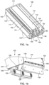
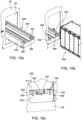
- the modular battery system 100 can include a battery assembly 102 and a counterweight assembly 108 configured to be removably secured to the battery assembly 102.
- the material handling vehicle 50 can include a battery compartment 60 dimensioned so that the battery assembly 102 and the counterweight assembly 108 can simultaneously fit therein.
- the battery assembly 102 can define a battery assembly front side 103, a battery assembly back side 104, a battery assembly left side 105, and a battery assembly right side 106, and can include a battery base 114 and a battery enclosure 116.
- the battery enclosure 116 can include an enclosure frame 118 configured to house at least one power source 120 in such a way that each power source 120 is removably secured within the battery enclosure 116, e.g., to the battery base 114.
- the power sources 120 can be coupled directly to the battery base 114 without inclusion of a battery enclosure 116.
- the battery assembly 102 can further include a left positioning portion 122 and a right positioning portion 124 which are coupled to and extend downwardly from the battery base 114 between the battery assembly front and back sides 103, 104.
- the left and right positioning portions 122, 124 can further be positioned proximate the battery assembly left and right sides 105, 106, respectively, and may be oriented so that they are parallel to the battery assembly left and right sides 105, 106.
- multiple individual sections of positioning features may be used in place of at least one of the left positioning portion 122 and the right positioning portion 124.
- a battery bracket 128 defining a battery bracket opening 129 can be coupled to the battery base 114 proximate the battery assembly front side 103, and may be positioned between the left and right positioning portions 122, 124.
- the battery assembly 102 can also include a plurality of roller bearings 126 which are rotatably coupled to at least one of the left positioning portion 122 and the right positioning portion 124, each roller bearing 126 optionally including an adjustable shimming puck (not shown).
- the roller bearings 126 can be spaced along the lengths of the positioning portions 122, 124 and are configured to provide a rolling interface between the battery assembly 102 and the counterweight assembly 108.
- At least one of the battery enclosure 116, the left positioning portion 122, the right positioning portion 124, and the battery bracket 128 may be integrally formed in the battery base 114. Additionally, the connections between at least one of the battery base 114, battery enclosure 116, the left positioning portion 122, the right positioning portion 124, the battery bracket 128, and the roller bearings 126 may vary. For example, at least one of the left positioning portion 122 and the right positioning portion 124 may be coupled directly to the battery enclosure 116 or to the power source 120, and the roller bearings 126 may be coupled directly to the battery base 114.
- the counterweight assembly 108 can define a counterweight assembly front side 109, a counterweight assembly back side 110, a counterweight assembly left side 111, and a counterweight assembly right side 112, and can include a counterweight base 130.
- the counterweight base 130 can include a left channel 132 and a right channel 134 formed in the counterweight base 130 between the counterweight assembly front and back sides 109, 110 and positioned proximate and parallel to the counterweight assembly left and right sides 111, 112, respectively.
- the counterweight base 130 can further include at least one counterweight bracket 136 defining a counterweight bracket opening 137, and at least one mounting opening 140 formed in the counterweight base 130.
- the counterweight assembly 108 can also include at least one counterweight mounting feature 142 protruding outwardly from the counterweight base 130, and the mounting feature 142 may include at least one ridge 144.
- a mounting feature 142 extends outwardly from each of the counterweight assembly left and right sides 111, 112, and each mounting feature 142 includes five ridges 144 spaced along the mounting feature 142 between the counterweight assembly front and back sides 109, 110.
- the quantity and configuration of the mounting features 142 and ridges 144 may vary.
- the left channel 132, the right channel 134, the counterweight bracket 136, and the mounting features 142 can be integrally formed in the counterweight base 130 or can be a separate component which is coupled to the counterweight base 130.
- the mounting opening 140 may be formed in a separate part coupled to the battery base 114.
- the mounting features 142 may include alternatively shaped projections in place of the ridges 144.
- cylindrical features (not shown) may be used in some non-limiting examples.
- the material handling vehicle 50 can include at least one slot (not shown) formed within the battery compartment 60.
- Each slot corresponds to one of the ridges 144 of the counterweight assembly 108 and is configured to engage the corresponding ridge 144. While at least one slot is engaged with a ridge 144, relative motion between the counterweight assembly 108 and the material handling vehicle 50 is restricted so that the counterweight assembly 108 is retained in the battery compartment 60.
- the battery compartment 60 can further include at least one compartment opening (not shown), wherein each of the compartment openings corresponds to a mounting opening 140. The compartment openings can further be configured so that, when the ridges 144 are engaged with the slots, the mounting openings 140 are concentric with the compartment openings.
- a bolt or another fastener may be used to secure the counterweight assembly 108 to the material handling vehicle 50.
- each of the channels 132, 134 can each include an entry notch 150 proximate the counterweight assembly front side 109, and can further be configured so that the left channel 132 and the right channel 134 can receive the roller bearings 126 coupled to the left positioning portion 122 and the right positioning portion 124, respectively, through the entry notches 150.
- the channels 132, 134 may restrict lateral motion of the roller bearings 126 to the left or to the right, and an upper portion 131 of each of the channels 132, 134 restricts vertical motion of the roller bearings 126.
- the roller bearings 126 of the battery assembly 102 can roll along a lower portion of each of the channels 132, 134 so that the battery assembly 102 moves towards the counterweight assembly back side 110 and so that additional roller bearings 126 enter the channels 132, 134 through the entry notches 150, and may continue rolling until at least one rolling bearing 126 abuts the counterweight assembly back side 110 at the end of the channels 132, 134.
- the battery bracket 128 and the counterweight bracket 136 may be positioned so that the battery bracket opening 129 and the counterweight bracket opening 137 are concentric with each other.
- a retention pin 152 can be inserted through the battery bracket opening 129 and the counterweight bracket opening 137, thereby coupling the battery assembly 102 to the counterweight assembly 108.
- a retainer ring 153 can be attached to the retention pin 152 to further retain the retention pin 152 in the battery bracket opening 129 and the counterweight bracket opening 137.
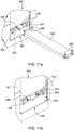
- the battery assembly 102 can be coupled to the material handling vehicle 50.
- the counterweight assembly 108 can be maneuvered into the battery compartment 60 through a compartment opening 65, leading with the counterweight assembly back side 110, so that the counterweight assembly 108 is fully inserted in the battery compartment 60 and the counterweight assembly front side 109 is positioned proximate the compartment opening 65.
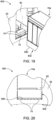
- the counterweight assembly 108 can then be maneuvered downward so the ridges 144 of the counterweight assembly 108 engage the slots of the material handling vehicle 50. Looking to FIG.
- the mounting pins 148 can be inserted into the mounting opening 140 and the corresponding enclosure opening, thereby coupling the counterweight assembly 108 to the material handling vehicle 50.
- the battery assembly 102 can be maneuvered so the set of roller bearings 126 closest to the battery assembly front side 103 enter the channels 132, 134 through the entry notches 150 and the battery assembly 102 is rolled into the battery compartment 60.
- the retention pin 152 can be inserted through the battery bracket opening 129 and the counterweight bracket opening 137, thereby securing the battery assembly 102 to the counterweight assembly 108 and indirectly to the material handling vehicle 50.
- a left positioning portion 222 and a right positioning portion 224 can respectively include a left channel 223 and a right channel 225
- the counterweight assembly 208 can include a plurality of roller bearings 226 rotatably coupled to a counterweight base 230.
- the left and right channels 223, 225 can be configured to receive the rolling bearings 226 so that the rolling bearings 226 are retained in the left and right channels 223, 225.
- the roller bearings 226 may provide a rolling interface between the battery assembly 202 and the counterweight assembly 208. This can enable the battery assembly 202 to be rolled into position to be removably coupled to the counterweight assembly 208.
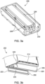
- the battery assembly 302 can include a battery base 314 with a plurality of battery retention openings 356 formed in a lower surface 358 of the battery base 314.
- the counterweight assembly 308 can include a counterweight base 330 which may have a plurality of counterweight retention openings 360 formed in an upper surface 362 of the counterweight base 330.
- the counterweight assembly 308 can further include at least one non-metal slide 364 coupled to the upper surface 362 of the counterweight base 360. The non-metal slide 364 can provide a sliding interface with the lower surface 358 of the battery base 314.
- a sliding interface can be formed between the lower surface 358 of the battery base 314 and the upper surface 362 of the counterweight base 330, and no non-metal slides 364 are included.
- the lower surface 358 of the battery base 314 can be received by the upper surface 362 of the counterweight base 330 so that the battery assembly 302 can be slid into position to be retained once the counterweight assembly 308 is in the battery compartment 60.
- At least one counterweight retention plate 349 can be coupled to the material handling vehicle 50 inside the battery compartment 60 and above the counterweight assembly 308 so that the counterweight assembly 308 is retained within the material handling vehicle 50.
- a plurality of retention pins 352 can be configured to simultaneously engage the battery retention openings 356 and the counterweight retention openings 360 to couple the battery base 314 to the counterweight base 330.
- At least one filler block 382 can be coupled to the counterweight base 330 proximate the retention pins 352 so that the retention pins 352 are retained in the battery retention openings 356 and the counterweight retention openings 360.
- the battery assembly 402 can include a battery base 412 and one positioning portion 468 coupled to the battery base 414.
- the positioning portion 468 can extend downwardly from the battery base 414 and can be positioned centrally with respect to the battery base 414.
- the counterweight assembly 408 can include a counterweight base 430 with a centrally positioned channel 470 defined by a left wall 472 and a right wall 474.
- a plurality of roller bearings 426 can be rotatably coupled to the left and right walls 472, 474 and may be positioned in recesses 476 formed in the left and right walls 472, 474.
- the roller bearings 426 can provide a rolling interface between the battery base 402 and the left and right walls 472, 474 of the counterweight base 430.
- the battery assembly 402 can be rolled on the roller bearings 426 so that the positioning portion 468 is received in the channel 470 through a first entryway 471.
- a retention plate 478 can be coupled to the counterweight base 430 with at least one fastener 479 so that the first entryway 471 is blocked by the retention plate 478, thereby coupling the battery assembly 402 and the counterweight assembly 408a.
- An additional retention bolt 480 can be used to further secure the battery assembly 402 to the counterweight assembly 408a.
- the channel 470 runs the entire length of the counterweight base 430 and an additional retention plate 478 may be utilized to block a second entryway 477 on the opposite side of the channel 470 as the first entry way 471.
- a counterweight base 408b ( FIG. 7b ) having at least one nonmetal slide 464 coupled to each of the left and right walls 472, 474 can be used in as an alternative to counterweight base 408 in the modular battery system 400.
- the battery assembly 502 can include a left positioning portion 522 and a right positioning portion 524 with at least one battery retention opening 556 formed in at least one of the left positioning portion 522 and the right positioning portion 524.
- the counterweight assembly 508 can include a left channel 532 and a right channel 534 coupled to a counterweight base 530, and a central void 584 formed between the left channel and right channels 532, 534.
- At least one pair of counterweight retention openings 557 corresponding to a battery retention opening 556 can be formed in at least one of the left channel 532 and the right channel 534 so that one of the pair of counterweight retention openings 557 is formed on either side of the left channel 532 or the right channel 534 and so that the pair of counterweight retention openings 557 are concentric.
- the left and right channels 532, 534 can be configured to receive the left and right positioning portions, respectively, allowing the battery assembly 502 to be slid into position to be coupled with the counterweight assembly 508.
- a retention pin 552 can be inserted into one of the counterweight retention opening 557 from the side of the central void 584 so that the retention pin 552 engages both of the pair of counterweight retention openings 557 and the corresponding battery retention opening 556.
- the filler plate 582 can be inserted into the central void 584 and may be coupled to the counterweight base 530 with at least one bolt 566. The filler plate 582 retains the retention pins 552 in the battery retention openings 556 and the counterweight retention opening 557, thereby coupling the battery base 514 to the counterweight base 530.
- the counterweight assembly 608 can include at least one positioning notch 690 formed in the bottom of the counterweight base 630.
- the positioning notches 690 can run longitudinally across the counterweight base and can be parallel to each other.
- Each one of the positioning notches 690 can be configures to receive a positioning bar 692 coupled to the material handling vehicle 50.
- the positioning bars 692 can be configured to restrict the motion of the counterweight assembly 108 with respect to the material handling vehicle 50 when the positioning bars 692 are engaged with the positioning notches 690.
- the positioning bars 692 may be connecter to a positioning bar frame 694 which can be coupled to the material handling vehicle.
- the positioning bars can also be separate parts, each individually coupled to the material handling vehicle 50, or can be integrally formed in the material handling vehicle 50.
- a modular battery system can include a battery assembly that can use interchangeable mounting structures in order to adapt to be compatible with a variety of different counterweight and battery compartment configurations.
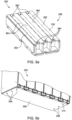
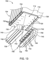
- a modular battery system 700 can include a counterweight assembly 702, a battery assembly 704, and one or more mounting structures 708.
- the one or more mounting structures 708 may be selectively secured to the battery assembly 704 and facilitate attachment of the battery assembly 704 to the counterweight assembly 702.
- the battery assembly 704 can include a battery base 712 secured to the bottom side of a battery enclosure 716, which may be configured to house at least one energy source (e.g., a lithium ion battery).
- a plurality of base or battery assembly openings 720 can be arranged in a standardized pattern on a bottom side 724 of the battery assembly 704.
- the base openings 720 can be formed in the battery base 712, and may be arranged in a linear array having two rows of base openings 720 that are laterally spaced from one another and that extend between a front side 728 and a back side 730 of the battery assembly 704.
- a battery assembly can include at least one base opening 720 that is arranged in a different pattern.
- some non-limiting examples can include a battery assembly with an array of openings formed in a different location.
- a standardized array of openings can be formed into a battery enclosure.
- a battery assembly may have a standardized pattern of openings that is different than the illustrated pattern.
- a battery base can include a pattern of base openings that includes more base openings or fewer base openings than the illustrated non-limiting example.
- a pattern of openings can also include an array with more rows or fewer rows than the illustrated pattern of openings.
- a pattern could include at least one of non-linear array (e.g., a lateral array), an irregular array, and a plurality of different arrays.
- the mounting structures 708 include a pair of channels 736 that are configured to be selectively coupled to the battery base 712.
- each of the channels 736 define a generally C-shaped channels.
- the channels 736 are laterally opposed to one another.
- Each of the channels 736 can include a base section 740 and two leg sections 742 extending laterally away (e.g., toward the opposing C-shaped channel) from opposite ends of the base section 740.
- At least one spacer 746 may be coupled to an outer surface 747 of the base section 740, and can extend along the longitudinal length (or a portion of the length) of the outer surface 747.
- each of the outer surfaces 747 include two spacers 746 coupled thereto that protrude laterally outwardly therefrom (i.e., a first spacer 746 coupled to the outer surface 747 and a second spacer 746 coupled to the first spacer 746).
- the spacers 746 may provide additional counterweight to the battery assembly 704, when the channels 736 are coupled to the battery assembly 704.
- Each of the channels 736 may include at least one channel or mounting structure opening 750 formed through at least one of the leg sections 742 and arranged in a pattern corresponding to the pattern of base openings 720 on the battery assembly 704.
- one of the leg sections 742 on each of the channels 736 on can include a plurality of channel openings 750 spaced longitudinally along the length of the leg section 742 in a pattern corresponding to at the base openings 720.
- a fastener 754 (e.g., a screw, pin, bolt, or any other fastener) can be installed into each of the base openings 720 through a corresponding one of the channel opening 750 in order to couple the mounting structure 708 to the bottom side 724 of the battery assembly 704.
- each of the channel openings 750 may correspond with one of the base openings 720 and can be configured to be engaged by a fastener 754. In this way, for example, the channels 736 may be selectively coupled to the battery assembly 704.
- a battery assembly according to the present disclosure may be configured to be coupled to more or less than two mounting structures. In some non-limiting examples, a battery assembly according to the present disclosure may be configured to be coupled to two differently shaped or designed mounting structures.
- the channels 736 can be coupled to the battery base 712 so that each of the channels 736 faces laterally inward towards the opposite channel 736.
- the gap between the two channels 736 can provide a counterweight-receiving slot 758 dimensioned to receive and engage the counterweight assembly 702.
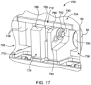
- the battery assembly 704 may include a battery bracket 760 defining a battery bracket opening (not shown) that extends from the bottom side 724 of the battery assembly 704, e.g., on the battery base 712 (see FIG. 17 ).
- the counterweight assembly 702 can include a counterweight base 770 configured to engage the battery compartment 60 of the material handling vehicle 50 (see FIGS. 15-17 ), and a central block 774 can be supported on the counterweight base 770.
- the central block 774 can protrude upwardly (e.g., from the perspective of FIG. 14 ) from the counterweight base 770, and can extend between a front side 776 and a back side 778 of the counterweight assembly 702.
- the lateral sides of the central block 774 are spaced from the lateral edges defined by the counterweight base 770. In other words, a gap or absence of space is arranged between the lateral sides of the central block 774 and the lateral edges of the counterweight base 770.
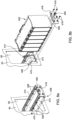
- the counterweight assembly 702 may include at least one roller bearing 780 configured to provide a rolling interface between the counterweight assembly 702 and the battery assembly 704.
- the central block 774 may include a first lateral surface 781 and a second lateral surface 782 that opposes the first lateral surface 781.
- Each of the first lateral surface 781 and the second lateral surface 782 may include at least one roller bearing 780 rotatably coupled thereto.
- each of the first lateral surface 781 and the second lateral surface 782 include two roller bearings 780 that are spaced from one another along the longitudinal direction of the central block 774.
- the first lateral surface 781 and the second lateral surface 782 may include more or less than two roller bearings 780 rotatably coupled thereto.
- Each of the first later surface 781 and the second lateral surface 782 may include a first bearing spacer 784 and a second bearing spacer 785.
- the first bearing spacer 784 may protrude laterally outwardly from the respective one of the first lateral surface 781 and the second lateral surface 782 and may extend longitudinally between the two roller bearings 780 arranged on the respective one of the first lateral surface 781 and the second lateral surface 782.
- the second bearing spacer 785 may protrude laterally outwardly from the respective one of the first lateral surface 781 and the second lateral surface 782 and may extend longitudinally from the back side 778 to a position adjacent to the one of the roller bearings 780 arranged adjacent to the back side 778.
- the counterweight assembly 702 may include at least one counterweight bracket 786 including a counterweight bracket opening 788.
- the central block 774 includes two laterally spaced counterweight brackets 786 arranged adjacent to the front side 776.
- Each of the counterweight brackets 786 may include a counterweight bracket opening 788 arranged therein and extending laterally therethrough.
- the counterweight assembly 702 secured within the battery compartment 60 of the material handling vehicle 50.
- the battery assembly 704 with the channels 736 attached thereto can be inserted onto the counterweight assembly 702.
- the battery assembly 704 can be inserted onto the counterweight assembly 702, so that the central block 774 slides into the counterweight-receiving slot 758 and the roller bearings 780 receive the channels 736 (see FIG. 15 ).
- the rolling interface between the roller bearings 780 and the channels 736 can then allow the battery assembly 704 to be rolled into the battery compartment 60.
- vertical movement of the battery assembly 704 can be restricted by the engagement between the roller bearings 780 and the channels 736.
- the battery bracket 760 may be arranged between the counterweight brackets 786, so that the counterweight bracket openings 788 axially align with the battery bracket opening (not shown).
- a retention pin 790 may be inserted through the counterweight bracket openings 788 and the battery bracket opening (not shown), and a washer 792 and a clip 794 may be used to prevent the retention pin 790 from being removed.
- the battery assembly 704 may be prevented from being removed from the counterweight assembly 702 (e.g., the roller bearings 780 may be prevented from displacing relative to the channels 736).
- non-limiting examples of the battery assembly 704 illustrated in FIGS. 13-17 may be configured to be coupled to at least one mounting structure that is different than the mounting structures 708 of FIGS. 13-17 .
- a mounting structure can include at least one of a positioning portion, a channel, a metal slide, a non-metal slide, a roller bearing, any other structure or feature that was described in conjunction with any of FIGS. 1-12 , or any other structure or feature configured for engaging a counterweight assembly.
- a battery assembly can be configured to be coupled to a plurality of different mounting structures.
- At least one mounting structure opening formed in each of the mounting structures can correspond to at least one battery assembly opening arranged in a standardized pattern of openings on the battery assembly, thereby making the plurality of mounting structures interchangeable. This can be useful, for example, so that one battery assembly may be used with multiple different counterweight assemblies.
- a battery assembly may be adapted to be secured to a counterweight assembly that has at least one of a positioning portion, a channel, a metal slide, a non-metal slide, a roller bearing, any other structure or feature that was described in conjunction with any of FIGS. 1-12 , or any other structure or feature for receiving a battery assembly.
- a mounting structure configured to secure a battery assembly to a first counterweight assembly can be removed from the battery assembly and interchanged for a different mounting structure in order to secure the battery assembly to a second, different counterweight assembly.
- some non-limiting examples can include a first battery base that is configured to be interchangeably secured to a battery enclosure and having a first pattern of base openings. The first battery base can be interchanged or replaced with a second battery base that includes a second, different pattern of openings, thereby enabling different mounting structures to be coupled to the battery assembly.
- a modular battery system can include a battery assembly that is configured to be coupled directly to a counterweight.
- a modular battery system 800 can include a counterweight 802 configured to be removably secured to the battery assembly 704.
- the counterweight 802 can include a plurality of counterweight openings 850 that extend through the counterweight 802 (e.g., from a lower surface 890 of the counterweight to an upper surface 892 from the perspective of FIG. 18 ), and that are arranged in a pattern corresponding to the standardized pattern of base openings 720 in the battery assembly 704.
- a fastener 854 can be inserted through each of the counterweight openings 850 to engage a corresponding one of the base openings 720, thereby securing the upper surface 892 of the counterweight 802 to the bottom side 724 of the battery assembly 704 and coupling the counterweight 802 to the battery assembly 704.
- the battery compartment 60 of the material handling vehicle 50 can include a roller assembly 70 with at least one roller 75 extending laterally across the battery compartment 60.
- the roller assembly 70 may include a plurality of rollers 75 spaced along the floor of the battery compartment 60.
- the rollers 75 can be configured to provide a rolling interface between the battery compartment 60 and the lower surface 890 of the counterweight 802, thereby enabling the battery assembly 704 to be rolled into the battery compartment 60.
Landscapes
- Chemical Kinetics & Catalysis (AREA)
- Electrochemistry (AREA)
- General Chemical & Material Sciences (AREA)
- Chemical & Material Sciences (AREA)
- Engineering & Computer Science (AREA)
- Transportation (AREA)
- Structural Engineering (AREA)
- Life Sciences & Earth Sciences (AREA)
- Mechanical Engineering (AREA)
- Civil Engineering (AREA)
- Geology (AREA)
- Aviation & Aerospace Engineering (AREA)
- Manufacturing & Machinery (AREA)
- Sustainable Development (AREA)
- Sustainable Energy (AREA)
- Power Engineering (AREA)
- Arrangement Or Mounting Of Propulsion Units For Vehicles (AREA)
- Battery Mounting, Suspending (AREA)
Claims (6)
- Modulares Batteriesystem für ein Materialhandhabungsfahrzeug, wobei das modulare Batteriesystem Folgendes umfasst:eine Gegengewichtsbaugruppe;eine Batteriebaugruppe, die eine Leistungsquelle umschließt und eine Batteriebasis beinhaltet; undein Paar von Kanälen, die abnehmbar an die Batteriebasis gekoppelt sind und jeweils mindestens einen Abstandshalter beinhalten, der an einer seitlich äußeren Fläche davon angebracht ist, wobei die Batteriebaugruppe dazu konfiguriert ist, verschiebbar an der Gegengewichtsbaugruppe installiert zu sein, und wobei jeder des mindestens einen Abstandshalters dazu konfiguriert ist, der Batteriebaugruppe zusätzliches Gegengewicht hinzuzufügen.
- Modulares Batteriesystem für ein Materialhandhabungsfahrzeug nach Anspruch 1, wobei die Kanäle seitlich voneinander getrennt sind, um dazwischen einen Gegengewichtsschlitz zu definieren, wobei bevorzugt die Gegengewichtsbaugruppe innerhalb des Gegengewichtsschlitzes aufgenommen ist, der zwischen dem Paar von Kanälen definiert ist.
- Modulares Batteriesystem nach Anspruch 2, ferner umfassend mindestens ein Wälzlager, das an die Gegengewichtsbaugruppe gekoppelt und dazu konfiguriert ist, eine Rollgrenzfläche zwischen dem Paar von Kanälen und der Gegengewichtsbaugruppe bereitzustellen.
- Modulares Batteriesystem nach Anspruch 2 oder 3, wobei die Gegengewichtsbaugruppe einen zentralen Block beinhaltet, der von einer zentralen Basis vorsteht, und wobei der zentrale Block eine erste seitliche Fläche und eine zweite seitliche Fläche definiert, wobei bevorzugt jede der ersten seitlichen Fläche und der zweiten seitlichen Fläche mindestens zwei Wälzlager beinhaltet, die längs voneinander getrennt sind, wobei weiter bevorzugt jede der ersten seitlichen Fläche und der zweiten seitlichen Fläche einen ersten Lagerabstandshalter, der längs zwischen den mindestens zwei Wälzlagern angeordnet ist, und einen zweiten Lagerabstandshalter, der benachbart zu einer Rückseite der Gegengewichtsbaugruppe angeordnet ist, beinhaltet.
- Modulares Batteriesystem nach einem der vorhergehenden Ansprüche, wobei die Gegengewichtsbaugruppe mindestens eine Gegengewichtshalterung beinhaltet, die eine sich dadurch erstreckende Gegengewichtshalterungsöffnung definiert, wobei bevorzugt die Batteriebaugruppe eine Batteriehalterung beinhaltet, die eine sich dadurch erstreckende Batteriehalterungsöffnung definiert, wobei weiter bevorzugt ein Arretierstift dazu konfiguriert ist, durch die Gegengewichtshalterungsöffnung und die Batteriehalterungsöffnung eingeführt zu werden, um die Batteriebaugruppe an der Gegengewichtsbaugruppe zu sichern.
- Modulares Batteriesystem nach einem der vorhergehenden Ansprüche, wobei die Batteriebaugruppe eine Vielzahl von Batteriebaugruppenöffnungen beinhaltet, die in einem vordefinierten Muster angeordnet ist, und wobei jeder des Paars von Kanälen eine Vielzahl von Kanalöffnungen beinhaltet, die dazu angeordnet ist, mit mindestens einem Abschnitt des vordefinierten Musters übereinzustimmen, das durch die Vielzahl von Batteriebaugruppenöffnungen definiert ist.
Applications Claiming Priority (1)
| Application Number | Priority Date | Filing Date | Title |
|---|---|---|---|
| US201962828777P | 2019-04-03 | 2019-04-03 |
Publications (3)
| Publication Number | Publication Date |
|---|---|
| EP3719862A1 EP3719862A1 (de) | 2020-10-07 |
| EP3719862C0 EP3719862C0 (de) | 2023-07-26 |
| EP3719862B1 true EP3719862B1 (de) | 2023-07-26 |
Family
ID=70110029
Family Applications (1)
| Application Number | Title | Priority Date | Filing Date |
|---|---|---|---|
| EP20166987.6A Active EP3719862B1 (de) | 2019-04-03 | 2020-03-31 | Systeme und verfahren für ein modulares batteriesystem |
Country Status (5)
| Country | Link |
|---|---|
| US (1) | US11233291B2 (de) |
| EP (1) | EP3719862B1 (de) |
| CN (1) | CN111799407B (de) |
| AU (1) | AU2020202104B2 (de) |
| CA (1) | CA3077204A1 (de) |
Families Citing this family (11)
| Publication number | Priority date | Publication date | Assignee | Title |
|---|---|---|---|---|
| US20220020973A1 (en) * | 2020-07-15 | 2022-01-20 | Kitty Hawk Corporation | Battery system with cylindrical cells |
| CN118651044A (zh) * | 2020-11-24 | 2024-09-17 | 奥动新能源汽车科技有限公司 | 电池托架及电动汽车 |
| CN113200478A (zh) * | 2021-03-22 | 2021-08-03 | 诺力智能装备股份有限公司 | 一种双向agv及其使用方法 |
| AU2022252693B2 (en) * | 2021-10-22 | 2025-07-17 | Crown Equipment Corporation | Battery guide pins for a battery receiving space of a materials handling vehicle, and materials handling vehicles incorporating the same |
| US12391107B2 (en) * | 2021-10-22 | 2025-08-19 | Crown Equipment Corporation | Battery guide pins for a battery receiving space of a materials handling vehicle, and materials handling vehicles incorporating the same |
| CN114436174B (zh) * | 2022-04-11 | 2022-07-05 | 杭叉集团股份有限公司 | 一种锂电专用架构前移式叉车 |
| CN115535928B (zh) * | 2022-11-28 | 2023-05-30 | 杭州远视测控技术有限公司 | 一种agv车辆牵引货物翻转卸货设备 |
| JP7513131B1 (ja) * | 2023-02-01 | 2024-07-09 | いすゞ自動車株式会社 | バッテリの着脱構造 |
| JP7513130B1 (ja) * | 2023-02-01 | 2024-07-09 | いすゞ自動車株式会社 | 規制装置 |
| CN119217951A (zh) * | 2023-06-30 | 2024-12-31 | 宁德时代新能源科技股份有限公司 | 电池安装架、车架组件和车辆 |
| DE102023136859A1 (de) * | 2023-12-29 | 2025-07-03 | Linde Material Handling Gmbh | Schubmaststapler |
Family Cites Families (19)
| Publication number | Priority date | Publication date | Assignee | Title |
|---|---|---|---|---|
| JP3526736B2 (ja) * | 1998-01-29 | 2004-05-17 | 日産ディーゼル工業株式会社 | バッテリ固定装置 |
| JP4269894B2 (ja) * | 2003-10-31 | 2009-05-27 | 株式会社豊田自動織機 | 産業車両におけるバッテリ保持機構 |
| DE102005051058A1 (de) * | 2005-10-25 | 2007-04-26 | Still Gmbh | Flurförderzeug mit einer bewegbaren Aufstandsfläche für einen Batterieblock |
| DE102006031461A1 (de) | 2006-07-07 | 2008-01-10 | Jungheinrich Aktiengesellschaft | Batteriewechselsystem für ein batteriebetriebenes Flurförderzeug |
| DE102006055363A1 (de) * | 2006-11-23 | 2008-06-26 | Still Gmbh | Gabelstapler mit einer Führung zum seitlichen Ausziehen eines Batterieblocks |
| JP2009274651A (ja) | 2008-05-16 | 2009-11-26 | Toyota Industries Corp | ハイブリッド産業車両 |
| US8852794B2 (en) | 2012-01-18 | 2014-10-07 | Battchange, Llc | Electric vehicle battery case |
| KR101561798B1 (ko) | 2012-03-27 | 2015-10-19 | 알리스 에코 에이알케이 코. 엘티디. | 전기자동차의 탈착식 배터리 고정 조립체 및 상기 조립체 고정 방법 |
| JP5590080B2 (ja) | 2012-08-13 | 2014-09-17 | 株式会社豊田自動織機 | 産業車両 |
| JP5692539B2 (ja) * | 2012-09-18 | 2015-04-01 | 株式会社豊田自動織機 | 産業車両 |
| JP5573932B2 (ja) * | 2012-12-14 | 2014-08-20 | 株式会社豊田自動織機 | 電池パック |
| CN104040754B (zh) | 2013-01-08 | 2016-02-10 | 株式会社小松制作所 | 作业机械用蓄电池壳体、作业机械用蓄电池单元、蓄电池式作业机械及蓄电池式叉车 |
| JP5621859B2 (ja) | 2013-01-25 | 2014-11-12 | 株式会社豊田自動織機 | 電池モジュール |
| US9972815B2 (en) * | 2014-02-05 | 2018-05-15 | Ford Global Technologies, Llc | Traction battery spacer with retention element |
| AU2017201690B2 (en) * | 2016-03-14 | 2022-09-15 | The Raymond Corporation | Battery counterweight system |
| CN106229431B (zh) | 2016-08-12 | 2019-04-05 | 系统电子科技(镇江)有限公司 | 一种电池包箱体安装用导轨及其安装方法 |
| CN110998898B (zh) | 2017-07-13 | 2023-03-10 | 电控装置有限责任公司 | 用于叉车的模块化锂离子电池系统 |
| DE102017119436A1 (de) * | 2017-08-24 | 2019-02-28 | Benteler Automobiltechnik Gmbh | Batterieträger für ein elektrisches Batteriemodul eines Fahrzeugs |
| AU2019213323B2 (en) | 2018-08-08 | 2024-08-29 | The Raymond Corporation | Systems and methods for a modular battery system |
-
2020
- 2020-03-24 US US16/828,232 patent/US11233291B2/en active Active
- 2020-03-25 AU AU2020202104A patent/AU2020202104B2/en active Active
- 2020-03-27 CA CA3077204A patent/CA3077204A1/en active Pending
- 2020-03-31 EP EP20166987.6A patent/EP3719862B1/de active Active
- 2020-04-02 CN CN202010254812.4A patent/CN111799407B/zh active Active
Also Published As
| Publication number | Publication date |
|---|---|
| EP3719862A1 (de) | 2020-10-07 |
| CN111799407A (zh) | 2020-10-20 |
| CA3077204A1 (en) | 2020-10-03 |
| US20200321569A1 (en) | 2020-10-08 |
| AU2020202104B2 (en) | 2025-08-21 |
| AU2020202104A1 (en) | 2020-10-22 |
| EP3719862C0 (de) | 2023-07-26 |
| CN111799407B (zh) | 2024-06-14 |
| US11233291B2 (en) | 2022-01-25 |
Similar Documents
| Publication | Publication Date | Title |
|---|---|---|
| EP3719862B1 (de) | Systeme und verfahren für ein modulares batteriesystem | |
| AU2019213323B2 (en) | Systems and methods for a modular battery system | |
| US7611799B2 (en) | Battery rack and system | |
| KR101839120B1 (ko) | 배터리 운반 트레이 | |
| US20050259404A1 (en) | Battery rack and system | |
| KR101192059B1 (ko) | 이차전지의 충전용 지그 및 이를 포함하는 충전용 장치 | |
| US7007786B2 (en) | Conveyor apparatus on a cargo deck of an aircraft | |
| US20150159684A1 (en) | Releasable mounting system for logistics track | |
| HK40037917A (en) | Systems and methods for a modular battery system | |
| HK40037917B (zh) | 用於模块化电池系统的系统和方法 | |
| KR102225251B1 (ko) | 두께조절용 카세트 조립체 및 이를 구비한 배터리용 트레이 | |
| KR102191400B1 (ko) | 폭조절용 카세트 조립체 및 이를 구비한 배터리용 트레이 | |
| CN105217212A (zh) | 收容装置、分区部以及形成多层收容部的方法 | |
| EP2149952B1 (de) | Träger für mehrere elektrische Mechanismen | |
| CN210744014U (zh) | 电池箱装置及电池箱系统 | |
| KR102191403B1 (ko) | 높이조절용 카세트 조립체 및 이를 구비한 배터리용 트레이 | |
| KR102247190B1 (ko) | 트레이 조립체 및 이를 구비한 배터리용 트레이 | |
| HK40023244A (en) | Systems and methods for a modular battery system | |
| CN216147706U (zh) | 一种滑道货架 | |
| KR101817146B1 (ko) | 축전지 안전 받침대 | |
| CN219619639U (zh) | 一种电池换型托盘 | |
| KR101843398B1 (ko) | 모듈형 축전지 안전 받침대 | |
| HK40023244B (zh) | 用於模块化电池系统的系统和方法 | |
| CN218883606U (zh) | 固定架和显示设备 | |
| US20080180009A1 (en) | Universal rack slide panel |
Legal Events
| Date | Code | Title | Description |
|---|---|---|---|
| PUAI | Public reference made under article 153(3) epc to a published international application that has entered the european phase |
Free format text: ORIGINAL CODE: 0009012 |
|
| STAA | Information on the status of an ep patent application or granted ep patent |
Free format text: STATUS: THE APPLICATION HAS BEEN PUBLISHED |
|
| AK | Designated contracting states |
Kind code of ref document: A1 Designated state(s): AL AT BE BG CH CY CZ DE DK EE ES FI FR GB GR HR HU IE IS IT LI LT LU LV MC MK MT NL NO PL PT RO RS SE SI SK SM TR |
|
| AX | Request for extension of the european patent |
Extension state: BA ME |
|
| STAA | Information on the status of an ep patent application or granted ep patent |
Free format text: STATUS: REQUEST FOR EXAMINATION WAS MADE |
|
| 17P | Request for examination filed |
Effective date: 20210331 |
|
| RBV | Designated contracting states (corrected) |
Designated state(s): AL AT BE BG CH CY CZ DE DK EE ES FI FR GB GR HR HU IE IS IT LI LT LU LV MC MK MT NL NO PL PT RO RS SE SI SK SM TR |
|
| REG | Reference to a national code |
Ref legal event code: R079 Ipc: H01M0050209000 Ref country code: DE Ref legal event code: R079 Ref document number: 602020014279 Country of ref document: DE Free format text: PREVIOUS MAIN CLASS: H01M0002100000 Ipc: H01M0050209000 |
|
| GRAP | Despatch of communication of intention to grant a patent |
Free format text: ORIGINAL CODE: EPIDOSNIGR1 |
|
| STAA | Information on the status of an ep patent application or granted ep patent |
Free format text: STATUS: GRANT OF PATENT IS INTENDED |
|
| RIC1 | Information provided on ipc code assigned before grant |
Ipc: H01M 50/264 20210101ALI20230202BHEP Ipc: H01M 50/244 20210101ALI20230202BHEP Ipc: H01M 50/209 20210101AFI20230202BHEP |
|
| INTG | Intention to grant announced |
Effective date: 20230222 |
|
| GRAS | Grant fee paid |
Free format text: ORIGINAL CODE: EPIDOSNIGR3 |
|
| GRAA | (expected) grant |
Free format text: ORIGINAL CODE: 0009210 |
|
| STAA | Information on the status of an ep patent application or granted ep patent |
Free format text: STATUS: THE PATENT HAS BEEN GRANTED |
|
| AK | Designated contracting states |
Kind code of ref document: B1 Designated state(s): AL AT BE BG CH CY CZ DE DK EE ES FI FR GB GR HR HU IE IS IT LI LT LU LV MC MK MT NL NO PL PT RO RS SE SI SK SM TR |
|
| REG | Reference to a national code |
Ref country code: CH Ref legal event code: EP |
|
| REG | Reference to a national code |
Ref country code: IE Ref legal event code: FG4D |
|
| REG | Reference to a national code |
Ref country code: DE Ref legal event code: R096 Ref document number: 602020014279 Country of ref document: DE |
|
| RAP4 | Party data changed (patent owner data changed or rights of a patent transferred) |
Owner name: THE RAYMOND CORPORATION |
|
| U01 | Request for unitary effect filed |
Effective date: 20230825 |
|
| U07 | Unitary effect registered |
Designated state(s): AT BE BG DE DK EE FI FR IT LT LU LV MT NL PT SE SI Effective date: 20230829 |
|
| REG | Reference to a national code |
Ref country code: LT Ref legal event code: MG9D |
|
| PG25 | Lapsed in a contracting state [announced via postgrant information from national office to epo] |
Ref country code: GR Free format text: LAPSE BECAUSE OF FAILURE TO SUBMIT A TRANSLATION OF THE DESCRIPTION OR TO PAY THE FEE WITHIN THE PRESCRIBED TIME-LIMIT Effective date: 20231027 |
|
| PG25 | Lapsed in a contracting state [announced via postgrant information from national office to epo] |
Ref country code: IS Free format text: LAPSE BECAUSE OF FAILURE TO SUBMIT A TRANSLATION OF THE DESCRIPTION OR TO PAY THE FEE WITHIN THE PRESCRIBED TIME-LIMIT Effective date: 20231126 |
|
| PG25 | Lapsed in a contracting state [announced via postgrant information from national office to epo] |
Ref country code: RS Free format text: LAPSE BECAUSE OF FAILURE TO SUBMIT A TRANSLATION OF THE DESCRIPTION OR TO PAY THE FEE WITHIN THE PRESCRIBED TIME-LIMIT Effective date: 20230726 Ref country code: NO Free format text: LAPSE BECAUSE OF FAILURE TO SUBMIT A TRANSLATION OF THE DESCRIPTION OR TO PAY THE FEE WITHIN THE PRESCRIBED TIME-LIMIT Effective date: 20231026 Ref country code: IS Free format text: LAPSE BECAUSE OF FAILURE TO SUBMIT A TRANSLATION OF THE DESCRIPTION OR TO PAY THE FEE WITHIN THE PRESCRIBED TIME-LIMIT Effective date: 20231126 Ref country code: HR Free format text: LAPSE BECAUSE OF FAILURE TO SUBMIT A TRANSLATION OF THE DESCRIPTION OR TO PAY THE FEE WITHIN THE PRESCRIBED TIME-LIMIT Effective date: 20230726 Ref country code: GR Free format text: LAPSE BECAUSE OF FAILURE TO SUBMIT A TRANSLATION OF THE DESCRIPTION OR TO PAY THE FEE WITHIN THE PRESCRIBED TIME-LIMIT Effective date: 20231027 |
|
| PG25 | Lapsed in a contracting state [announced via postgrant information from national office to epo] |
Ref country code: PL Free format text: LAPSE BECAUSE OF FAILURE TO SUBMIT A TRANSLATION OF THE DESCRIPTION OR TO PAY THE FEE WITHIN THE PRESCRIBED TIME-LIMIT Effective date: 20230726 |
|
| U20 | Renewal fee for the european patent with unitary effect paid |
Year of fee payment: 5 Effective date: 20240207 |
|
| PG25 | Lapsed in a contracting state [announced via postgrant information from national office to epo] |
Ref country code: ES Free format text: LAPSE BECAUSE OF FAILURE TO SUBMIT A TRANSLATION OF THE DESCRIPTION OR TO PAY THE FEE WITHIN THE PRESCRIBED TIME-LIMIT Effective date: 20230726 |
|
| REG | Reference to a national code |
Ref country code: DE Ref legal event code: R097 Ref document number: 602020014279 Country of ref document: DE |
|
| PG25 | Lapsed in a contracting state [announced via postgrant information from national office to epo] |
Ref country code: SM Free format text: LAPSE BECAUSE OF FAILURE TO SUBMIT A TRANSLATION OF THE DESCRIPTION OR TO PAY THE FEE WITHIN THE PRESCRIBED TIME-LIMIT Effective date: 20230726 Ref country code: RO Free format text: LAPSE BECAUSE OF FAILURE TO SUBMIT A TRANSLATION OF THE DESCRIPTION OR TO PAY THE FEE WITHIN THE PRESCRIBED TIME-LIMIT Effective date: 20230726 Ref country code: ES Free format text: LAPSE BECAUSE OF FAILURE TO SUBMIT A TRANSLATION OF THE DESCRIPTION OR TO PAY THE FEE WITHIN THE PRESCRIBED TIME-LIMIT Effective date: 20230726 Ref country code: CZ Free format text: LAPSE BECAUSE OF FAILURE TO SUBMIT A TRANSLATION OF THE DESCRIPTION OR TO PAY THE FEE WITHIN THE PRESCRIBED TIME-LIMIT Effective date: 20230726 Ref country code: SK Free format text: LAPSE BECAUSE OF FAILURE TO SUBMIT A TRANSLATION OF THE DESCRIPTION OR TO PAY THE FEE WITHIN THE PRESCRIBED TIME-LIMIT Effective date: 20230726 |
|
| PLBE | No opposition filed within time limit |
Free format text: ORIGINAL CODE: 0009261 |
|
| STAA | Information on the status of an ep patent application or granted ep patent |
Free format text: STATUS: NO OPPOSITION FILED WITHIN TIME LIMIT |
|
| 26N | No opposition filed |
Effective date: 20240429 |
|
| REG | Reference to a national code |
Ref country code: CH Ref legal event code: PL |
|
| PG25 | Lapsed in a contracting state [announced via postgrant information from national office to epo] |
Ref country code: MC Free format text: LAPSE BECAUSE OF FAILURE TO SUBMIT A TRANSLATION OF THE DESCRIPTION OR TO PAY THE FEE WITHIN THE PRESCRIBED TIME-LIMIT Effective date: 20230726 |
|
| PG25 | Lapsed in a contracting state [announced via postgrant information from national office to epo] |
Ref country code: MC Free format text: LAPSE BECAUSE OF FAILURE TO SUBMIT A TRANSLATION OF THE DESCRIPTION OR TO PAY THE FEE WITHIN THE PRESCRIBED TIME-LIMIT Effective date: 20230726 |
|
| PG25 | Lapsed in a contracting state [announced via postgrant information from national office to epo] |
Ref country code: IE Free format text: LAPSE BECAUSE OF NON-PAYMENT OF DUE FEES Effective date: 20240331 |
|
| PG25 | Lapsed in a contracting state [announced via postgrant information from national office to epo] |
Ref country code: IE Free format text: LAPSE BECAUSE OF NON-PAYMENT OF DUE FEES Effective date: 20240331 Ref country code: CH Free format text: LAPSE BECAUSE OF NON-PAYMENT OF DUE FEES Effective date: 20240331 |
|
| U20 | Renewal fee for the european patent with unitary effect paid |
Year of fee payment: 6 Effective date: 20250205 |
|
| PG25 | Lapsed in a contracting state [announced via postgrant information from national office to epo] |
Ref country code: CY Free format text: LAPSE BECAUSE OF FAILURE TO SUBMIT A TRANSLATION OF THE DESCRIPTION OR TO PAY THE FEE WITHIN THE PRESCRIBED TIME-LIMIT; INVALID AB INITIO Effective date: 20200331 |
|
| PG25 | Lapsed in a contracting state [announced via postgrant information from national office to epo] |
Ref country code: HU Free format text: LAPSE BECAUSE OF FAILURE TO SUBMIT A TRANSLATION OF THE DESCRIPTION OR TO PAY THE FEE WITHIN THE PRESCRIBED TIME-LIMIT; INVALID AB INITIO Effective date: 20200331 |
|
| PG25 | Lapsed in a contracting state [announced via postgrant information from national office to epo] |
Ref country code: TR Free format text: LAPSE BECAUSE OF FAILURE TO SUBMIT A TRANSLATION OF THE DESCRIPTION OR TO PAY THE FEE WITHIN THE PRESCRIBED TIME-LIMIT Effective date: 20230726 |
|
| U20 | Renewal fee for the european patent with unitary effect paid |
Year of fee payment: 7 Effective date: 20260209 |
|
| PGFP | Annual fee paid to national office [announced via postgrant information from national office to epo] |
Ref country code: GB Payment date: 20260209 Year of fee payment: 7 |