EP3719480A1 - Ein fluormesser zur messung der fluoreszenz einer probe - Google Patents
Ein fluormesser zur messung der fluoreszenz einer probe Download PDFInfo
- Publication number
- EP3719480A1 EP3719480A1 EP20169090.6A EP20169090A EP3719480A1 EP 3719480 A1 EP3719480 A1 EP 3719480A1 EP 20169090 A EP20169090 A EP 20169090A EP 3719480 A1 EP3719480 A1 EP 3719480A1
- Authority
- EP
- European Patent Office
- Prior art keywords
- electromagnetic radiation
- sample
- fluorometer
- excitation
- beam path
- Prior art date
- Legal status (The legal status is an assumption and is not a legal conclusion. Google has not performed a legal analysis and makes no representation as to the accuracy of the status listed.)
- Granted
Links
- 230000005284 excitation Effects 0.000 claims abstract description 138
- 230000005670 electromagnetic radiation Effects 0.000 claims abstract description 125
- WJJMNDUMQPNECX-UHFFFAOYSA-N dipicolinic acid Chemical compound OC(=O)C1=CC=CC(C(O)=O)=N1 WJJMNDUMQPNECX-UHFFFAOYSA-N 0.000 claims description 40
- 239000000126 substance Substances 0.000 claims description 36
- 229920006395 saturated elastomer Polymers 0.000 claims description 5
- 238000000034 method Methods 0.000 claims description 4
- 239000004417 polycarbonate Substances 0.000 claims description 2
- 229920000515 polycarbonate Polymers 0.000 claims description 2
- 229920001343 polytetrafluoroethylene Polymers 0.000 claims description 2
- 230000000903 blocking effect Effects 0.000 claims 1
- -1 polytetrafluoroethylene Polymers 0.000 claims 1
- 239000004810 polytetrafluoroethylene Substances 0.000 claims 1
- 239000000523 sample Substances 0.000 description 69
- 239000000243 solution Substances 0.000 description 17
- 238000004140 cleaning Methods 0.000 description 13
- 238000002834 transmittance Methods 0.000 description 11
- 238000005259 measurement Methods 0.000 description 10
- 230000003595 spectral effect Effects 0.000 description 9
- 230000035945 sensitivity Effects 0.000 description 8
- 239000000203 mixture Substances 0.000 description 6
- 238000001228 spectrum Methods 0.000 description 5
- XLYOFNOQVPJJNP-UHFFFAOYSA-N water Substances O XLYOFNOQVPJJNP-UHFFFAOYSA-N 0.000 description 5
- 239000000853 adhesive Substances 0.000 description 4
- 230000001070 adhesive effect Effects 0.000 description 4
- 230000000845 anti-microbial effect Effects 0.000 description 4
- 150000001875 compounds Chemical class 0.000 description 4
- 239000003599 detergent Substances 0.000 description 4
- 230000000813 microbial effect Effects 0.000 description 4
- 210000004215 spore Anatomy 0.000 description 4
- 239000004599 antimicrobial Substances 0.000 description 3
- 238000002284 excitation--emission spectrum Methods 0.000 description 3
- 239000012530 fluid Substances 0.000 description 3
- 238000002189 fluorescence spectrum Methods 0.000 description 3
- 239000000463 material Substances 0.000 description 3
- 230000003287 optical effect Effects 0.000 description 3
- 230000005855 radiation Effects 0.000 description 3
- 230000001105 regulatory effect Effects 0.000 description 3
- 239000000654 additive Substances 0.000 description 2
- 210000004666 bacterial spore Anatomy 0.000 description 2
- 235000013361 beverage Nutrition 0.000 description 2
- 239000000645 desinfectant Substances 0.000 description 2
- 230000000249 desinfective effect Effects 0.000 description 2
- 238000000695 excitation spectrum Methods 0.000 description 2
- 235000013305 food Nutrition 0.000 description 2
- 239000011521 glass Substances 0.000 description 2
- 238000004519 manufacturing process Methods 0.000 description 2
- 239000000575 pesticide Substances 0.000 description 2
- 238000011012 sanitization Methods 0.000 description 2
- GFISHBQNVWAVFU-UHFFFAOYSA-K terbium(iii) chloride Chemical compound Cl[Tb](Cl)Cl GFISHBQNVWAVFU-UHFFFAOYSA-K 0.000 description 2
- 238000011282 treatment Methods 0.000 description 2
- 238000005406 washing Methods 0.000 description 2
- 238000003466 welding Methods 0.000 description 2
- YZCKVEUIGOORGS-OUBTZVSYSA-N Deuterium Chemical compound [2H] YZCKVEUIGOORGS-OUBTZVSYSA-N 0.000 description 1
- 239000004809 Teflon Substances 0.000 description 1
- 229920006362 Teflon® Polymers 0.000 description 1
- 239000002253 acid Substances 0.000 description 1
- 150000007513 acids Chemical class 0.000 description 1
- 230000006978 adaptation Effects 0.000 description 1
- 239000012670 alkaline solution Substances 0.000 description 1
- 230000003373 anti-fouling effect Effects 0.000 description 1
- 238000009455 aseptic packaging Methods 0.000 description 1
- 230000002238 attenuated effect Effects 0.000 description 1
- 239000003139 biocide Substances 0.000 description 1
- 238000004061 bleaching Methods 0.000 description 1
- 230000015556 catabolic process Effects 0.000 description 1
- 230000001413 cellular effect Effects 0.000 description 1
- 239000003795 chemical substances by application Substances 0.000 description 1
- 230000003749 cleanliness Effects 0.000 description 1
- 238000000576 coating method Methods 0.000 description 1
- 238000010276 construction Methods 0.000 description 1
- 238000005260 corrosion Methods 0.000 description 1
- 230000007797 corrosion Effects 0.000 description 1
- 230000008878 coupling Effects 0.000 description 1
- 238000010168 coupling process Methods 0.000 description 1
- 238000005859 coupling reaction Methods 0.000 description 1
- 230000003247 decreasing effect Effects 0.000 description 1
- 238000006731 degradation reaction Methods 0.000 description 1
- 238000001514 detection method Methods 0.000 description 1
- 229910052805 deuterium Inorganic materials 0.000 description 1
- 238000007865 diluting Methods 0.000 description 1
- 238000010790 dilution Methods 0.000 description 1
- 239000012895 dilution Substances 0.000 description 1
- 239000000975 dye Substances 0.000 description 1
- 230000000694 effects Effects 0.000 description 1
- 230000008030 elimination Effects 0.000 description 1
- 238000003379 elimination reaction Methods 0.000 description 1
- 230000002708 enhancing effect Effects 0.000 description 1
- 238000001914 filtration Methods 0.000 description 1
- 230000006870 function Effects 0.000 description 1
- 230000008570 general process Effects 0.000 description 1
- 239000003752 hydrotrope Substances 0.000 description 1
- 238000007654 immersion Methods 0.000 description 1
- 239000003112 inhibitor Substances 0.000 description 1
- 239000007788 liquid Substances 0.000 description 1
- 239000000314 lubricant Substances 0.000 description 1
- 238000005461 lubrication Methods 0.000 description 1
- 235000013372 meat Nutrition 0.000 description 1
- QSHDDOUJBYECFT-UHFFFAOYSA-N mercury Chemical compound [Hg] QSHDDOUJBYECFT-UHFFFAOYSA-N 0.000 description 1
- 229910052753 mercury Inorganic materials 0.000 description 1
- 229910052751 metal Inorganic materials 0.000 description 1
- 239000002184 metal Substances 0.000 description 1
- 244000005700 microbiome Species 0.000 description 1
- 230000004048 modification Effects 0.000 description 1
- 238000012986 modification Methods 0.000 description 1
- 238000004806 packaging method and process Methods 0.000 description 1
- 239000004033 plastic Substances 0.000 description 1
- 244000144977 poultry Species 0.000 description 1
- 235000013594 poultry meat Nutrition 0.000 description 1
- 239000000047 product Substances 0.000 description 1
- 230000009467 reduction Effects 0.000 description 1
- 239000012266 salt solution Substances 0.000 description 1
- 229910052594 sapphire Inorganic materials 0.000 description 1
- 239000010980 sapphire Substances 0.000 description 1
- 235000014102 seafood Nutrition 0.000 description 1
- 238000005476 soldering Methods 0.000 description 1
- 239000002904 solvent Substances 0.000 description 1
- 230000005236 sound signal Effects 0.000 description 1
- 229910001220 stainless steel Inorganic materials 0.000 description 1
- 239000010935 stainless steel Substances 0.000 description 1
- 239000004094 surface-active agent Substances 0.000 description 1
- 230000002277 temperature effect Effects 0.000 description 1
- 230000000007 visual effect Effects 0.000 description 1
Images


Classifications
-
- G—PHYSICS
- G01—MEASURING; TESTING
- G01N—INVESTIGATING OR ANALYSING MATERIALS BY DETERMINING THEIR CHEMICAL OR PHYSICAL PROPERTIES
- G01N21/00—Investigating or analysing materials by the use of optical means, i.e. using sub-millimetre waves, infrared, visible or ultraviolet light
- G01N21/62—Systems in which the material investigated is excited whereby it emits light or causes a change in wavelength of the incident light
- G01N21/63—Systems in which the material investigated is excited whereby it emits light or causes a change in wavelength of the incident light optically excited
- G01N21/64—Fluorescence; Phosphorescence
- G01N21/645—Specially adapted constructive features of fluorimeters
-
- G—PHYSICS
- G01—MEASURING; TESTING
- G01N—INVESTIGATING OR ANALYSING MATERIALS BY DETERMINING THEIR CHEMICAL OR PHYSICAL PROPERTIES
- G01N21/00—Investigating or analysing materials by the use of optical means, i.e. using sub-millimetre waves, infrared, visible or ultraviolet light
- G01N21/62—Systems in which the material investigated is excited whereby it emits light or causes a change in wavelength of the incident light
- G01N21/63—Systems in which the material investigated is excited whereby it emits light or causes a change in wavelength of the incident light optically excited
- G01N21/64—Fluorescence; Phosphorescence
- G01N21/6428—Measuring fluorescence of fluorescent products of reactions or of fluorochrome labelled reactive substances, e.g. measuring quenching effects, using measuring "optrodes"
-
- G—PHYSICS
- G01—MEASURING; TESTING
- G01N—INVESTIGATING OR ANALYSING MATERIALS BY DETERMINING THEIR CHEMICAL OR PHYSICAL PROPERTIES
- G01N21/00—Investigating or analysing materials by the use of optical means, i.e. using sub-millimetre waves, infrared, visible or ultraviolet light
- G01N21/62—Systems in which the material investigated is excited whereby it emits light or causes a change in wavelength of the incident light
- G01N21/63—Systems in which the material investigated is excited whereby it emits light or causes a change in wavelength of the incident light optically excited
- G01N21/64—Fluorescence; Phosphorescence
- G01N21/6486—Measuring fluorescence of biological material, e.g. DNA, RNA, cells
-
- G—PHYSICS
- G01—MEASURING; TESTING
- G01N—INVESTIGATING OR ANALYSING MATERIALS BY DETERMINING THEIR CHEMICAL OR PHYSICAL PROPERTIES
- G01N21/00—Investigating or analysing materials by the use of optical means, i.e. using sub-millimetre waves, infrared, visible or ultraviolet light
- G01N21/84—Systems specially adapted for particular applications
- G01N21/85—Investigating moving fluids or granular solids
- G01N21/8507—Probe photometers, i.e. with optical measuring part dipped into fluid sample
-
- G—PHYSICS
- G01—MEASURING; TESTING
- G01N—INVESTIGATING OR ANALYSING MATERIALS BY DETERMINING THEIR CHEMICAL OR PHYSICAL PROPERTIES
- G01N21/00—Investigating or analysing materials by the use of optical means, i.e. using sub-millimetre waves, infrared, visible or ultraviolet light
- G01N21/84—Systems specially adapted for particular applications
- G01N21/88—Investigating the presence of flaws or contamination
- G01N21/8806—Specially adapted optical and illumination features
-
- G—PHYSICS
- G01—MEASURING; TESTING
- G01N—INVESTIGATING OR ANALYSING MATERIALS BY DETERMINING THEIR CHEMICAL OR PHYSICAL PROPERTIES
- G01N21/00—Investigating or analysing materials by the use of optical means, i.e. using sub-millimetre waves, infrared, visible or ultraviolet light
- G01N21/62—Systems in which the material investigated is excited whereby it emits light or causes a change in wavelength of the incident light
- G01N21/63—Systems in which the material investigated is excited whereby it emits light or causes a change in wavelength of the incident light optically excited
- G01N21/64—Fluorescence; Phosphorescence
- G01N21/645—Specially adapted constructive features of fluorimeters
- G01N2021/6463—Optics
- G01N2021/6471—Special filters, filter wheel
-
- G—PHYSICS
- G01—MEASURING; TESTING
- G01N—INVESTIGATING OR ANALYSING MATERIALS BY DETERMINING THEIR CHEMICAL OR PHYSICAL PROPERTIES
- G01N2201/00—Features of devices classified in G01N21/00
- G01N2201/06—Illumination; Optics
- G01N2201/068—Optics, miscellaneous
Definitions
- This disclosure generally relates to systems and methods for measuring concentration of chemicals in a solution. More particularly, this disclosure relates to systems and methods involving a fluorometer for measuring concentration of chemicals in a solution.
- Cleaning operations in public facilities such as restaurants, hotels, food and beverage plants, hospital, etc. typically uses a cleaning product having sanitizing, disinfecting and/or antimicrobial properties.
- cleaning products may interact with certain chemical compounds (e.g., dipicolinic acid) present in some microbial spores to destroy microbes.
- certain chemical compound may be added to cleaning products to improve their chemical stability and/or shelf-life.
- dipicolinic acid can be added to certain cleaning products to improve their resistance to heat, thereby reducing the rate of degradation of the cleaning products when exposed to heat and extending the use of such cleaning products in regions with warm climates.
- the concentration of dipicolinic acid may be measured in a number of situations. For instance, regulatory standards may require that the concentration of microbial spores not exceed a given value in a public facility. By measuring the concentration of dipicolinic acid, the concentration of microbial spores may then be determined to comply with any regulatory standard. In another example, it may be necessary to maintain a certain concentration of dipicolinic acid to improve the stability of cleaning products.
- dipicolinic acid exhibits fluorescence when excited by electromagnetic radiation of certain wavelengths
- the concentration of dipicolinic acid in a solution can be measured by measuring the fluorescence of the solution.
- the intensity of fluorescence emitted by the solution may depend on the concentration of dipicolinic acid in the solution. For instance, the intensity of fluorescence emitted by the solution may be directly proportion to the concentration of dipicolinic acid. By measuring the intensity of the fluorescence emitted by dipicolinic acid, the concentration of dipicolinic acid can therefore be determined.
- Fluorometers for measuring fluorescence of a sample are relatively well known.
- An exemplary fluorometer for measuring fluorescence is disclosed in U.S. Pat. No. 8,269,193 and U.S. Pat. No. 8,352,207 both assigned to Ecolab Inc., St. Paul, MN, the disclosure of each of which is here by incorporated by reference in its entirety.
- Fluorometers generally have of a source of electromagnetic radiation that can excite a sample (e.g., dipicolinic acid solution of an unknown concentration), and a detector adapted to measure the intensity of fluorescence emitted by the electromagnetic radiation.
- the concentration of a substance of interest (e.g., dipicolinic acid) in a solution may be very low.
- regulatory requirements may necessitate that only a minimum level of the substance of interest (e.g., microbes) is present in a target area (e.g., a healthcare facility, food and beverage production and packaging facility).
- the intensity of fluorescence emitted by such substances of interest can be proportional to their concentration.
- Low concentrations e.g., on the order of a few hundred parts per billion
- the fluorescence may decrease directly proportional to the decrease in concentration (or by diluting the substance of interest).
- Typical fluorometers known in the art may not be able to measure such low levels of fluorescence with high accuracy and sensitivity.
- Certain embodiments of the invention include a fluorometer for measuring fluorescence of a sample.
- the fluorometer can include a housing, a controller supported by the housing, and a sensor head.
- the sensor head can include an emitter module and a detector module operatively coupled to the controller.
- the emitter module can include an excitation source configured for emitting electromagnetic radiation at one or more wavelengths to induce fluorescence in the sample.
- the emission of the electromagnetic radiation can be directed along a first beam path.
- the sensor head can include an excitation filter for transmitting electromagnetic radiation within a first wavelength range toward the sample.
- the excitation filter can be supported by an excitation filter holder.
- the excitation filter holder can define an aperture for passage of electromagnetic radiation.
- the excitation filter holder can support the excitation filter such that the excitation filter permits passage of filtered electromagnetic radiation through the aperture and towards the sample such that the first beam path defines a trajectory of electromagnetic radiation from the excitation source to the excitation filter, via the aperture and toward the sample.
- the detector module can detect fluorescence emitted by the sample.
- the fluorometer displays the concentration of the substance in the sample determined by the controller, based on the measured fluorescence.
- the fluorometer includes a first focusing apparatus and a second focusing apparatus.
- the first focusing apparatus and the second focusing apparatus can be housed in the housing proximate the sensor head.
- the first focusing apparatus can direct electromagnetic radiation originating from the excitation source and transmitted by the excitation filter towards the sample.
- the second focusing apparatus can direct fluorescence originating from the sample toward the detector module.
- the aperture can be positioned asymmetrically relative to the first beam path such that the aperture passes an asymmetrical portion of the electromagnetic radiation in the first beam path and the excitation filter holder blocks passage of a corresponding asymmetrical portion of the electromagnetic radiation in the first beam path.
- the blocked passage of the corresponding asymmetrical portion of the electromagnetic radiation in the first beam path can reduce the amount of electromagnetic radiation oriented directly from the emitter module to the detector module.
- the aperture is of semi-circular cross-section.
- the aperture is shaped by obstructing at least a portion of a circular opening.
- the aperture is shaped to prevent electromagnetic radiation passing through the first focusing apparatus from being directed toward the second focusing apparatus.
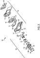
- FIGS. 1 and 2 are perspective and exploded views, respectively, of a fluorometer 100 according to some embodiments of the invention.
- the fluorometer 100 can be useful for measuring fluorescence emitted by certain samples.
- the fluorometer 100 can facilitate determining the concentration of certain samples in a solution based on the measured fluorescence.
- Such embodiments can be useful for measuring intensity of fluorescence emitted by samples such as dipicolinic acid and other chemicals (e.g., found in cleaning products). Based on the measured intensity of emitted fluorescence, the concentration of dipicolinic acid in a solution (e.g., a sanitizer, disinfectant, detergent, and the like) can be determined.
- a solution e.g., a sanitizer, disinfectant, detergent, and the like
- the fluorometer 100 can measure intensity of fluorescent emission from a sample (e.g., a chemical solution, such as an antimicrobial or cleaning product) having a substance of interest (e.g., dipicolinic acid).
- the fluorometer 100 can calculate concentration of the substance in the sample, and display the determined concentration to a user. The user can then perform any desired actions based on the determined concentration, such as, for example, adding more of the substance in order to increase the concentration of the substance. If the fluorometer 100 determines that the concentration is lower or higher than a threshold concentration, the user can dispense more or less of the substance.
- the fluorometer 100 can be operatively coupled to an out-of-product sensor.
- the fluorescence emitted by the substance may be at a lower intensity.
- the out-of-product sensor can alert the user that the concentration of the substance has reached below a pre-determined threshold.
- the signal can be a visual, audio signal, or any other type of signal known in the art. Accordingly, the user can ensure that sufficient quantity and/or concentration of cleaning, antimicrobial, sanitizing and/or disinfecting solution, or other substances of interest is present to achieve the desired effect (cleanliness, reduction in microorganisms, heat resistance, product stability, lubrication, etc.).
- the fluorometer 100 can calculate a concentration of a particular substance in a sample based on fluorescent properties of the substance.
- the fluorometer 100 includes an excitation source 158 that emits electromagnetic radiation at one or more selected wavelengths, or continuously within a wavelength range.
- electromagnetic radiation can be of a different energy (i.e., at another wavelength range) from the electromagnetic radiation emitted by the excitation source 158.
- the electromagnetic radiation emitted by the substance can then be converted into an electrical signal.
- the electrical signal can indicate the intensity of fluorescent emissions.
- the concentration of the substance can then be determined based on a known relationship between the intensity of the fluorescent emissions and the concentration of the substance (e.g., via a calibration).
- the concentration of water treatment products or solutions may be determined.
- the substance of interest may be any chemical solution. Examples include, but are not limited to, biocides such as pesticide and antimicrobial products, anticorrosion, antiscaling, and antifouling products, disinfectants, and other cleaning products, detergents, additives, surfactants, lubricants, antimicrobial agents, solvents, hydrotropes, antiredeposition agents, dyes, corrosion inhibitors, acids, alkaline solutions, salt solutions, and bleaching additives.
- biocides such as pesticide and antimicrobial products, anticorrosion, antiscaling, and antifouling products, disinfectants, and other cleaning products, detergents, additives, surfactants, lubricants, antimicrobial agents, solvents, hydrotropes, antiredeposition agents, dyes, corrosion inhibitors, acids, alkaline solutions, salt solutions, and bleaching additives.
- the fluorometer 100 includes a sensor head 102.
- the sensor head 102 can be made from a plastic and may be molded and/or milled to achieve the desired shape and features.
- the sensor head 102 includes a fluid-tight sensor head housing 104 (e.g., O-ring seals) that facilitates operation of the fluorometer 100 when partially or wholly immersed in a fluid sample of interest, and protects various components of the sensor head 102 from exposure to fluids.
- the sensor head 102 has some features and/or characteristics similar to an immersible dip probe.
- the sensor head 102 has one or more features and/or components similar to those described in commonly-assigned U.S.
- the sensor head 102 can be immersed into a sample container (not shown) to measure fluorescence and/or concentration.
- the fluorometer 100 also includes an electronic display 106 for displaying data (e.g., concentration, intensity), to a user, and an input interface in the form of the keypad 108 that allows the user to interact with the fluorometer 100 (e.g., saving measured concentration or intensity, setting parameters for measurement, viewing previously stored measurement data, etc.).
- data e.g., concentration, intensity
- input interface in the form of the keypad 108 that allows the user to interact with the fluorometer 100 (e.g., saving measured concentration or intensity, setting parameters for measurement, viewing previously stored measurement data, etc.).
- the sensor head 102 can be connected to a controller module 110.
- the controller module 110 has a controller housing 112 which provides a convenient form, similar to a handle or wand, to easily grasp or hold the fluorometer 100 by hand.
- the controller module 110 generally includes those components necessary to determine a concentration of a product based on a signal received from the sensor head 102.
- the controller module 110 includes a controller board 114 that couples with a display board 116 via a display board cable.
- the display board 116 allows the electronic display 106 (e.g., an LCD screen) to display information (e.g., measured concentration, intensity of fluorescence) to a user.
- the controller module 110 also includes an input interface in the form of a keypad 108.
- the controller module 110 also includes a portable power source 120, (e.g., battery) for powering the fluorometer 100.
- the sensor head 102 is connected to (e.g., by fasteners or adhesives) or integral with a bottom surface 122 of the controller housing 112 opposite from the electronic display 106 and positioned proximate a distal end 124 of the controller housing 112.
- the sensor head 102 housing is fixedly attached to the bottom surface 122 of the controller housing 112.
- the sensor head housing 104 may be integrally formed with at least a portion of the controller housing 112. In one example, a user can grasp the controller housing 112 near a proximal end 126 of the controller housing 112 to take measurements from a sample.
- the user can grasp the controller housing 112 near the proximal end 126 of the controller housing 112 to read the electronic display 106, and/or to manipulate the keypad 108.
- a user may dip the sensor head 102 into a sample by holding the controller module 110 above the surface of a sample (e.g., in a reservoir, container, beaker, etc.) with the sensor head 102 partially or completely immersed in the sample.
- a user may grasp the proximal end 126 of the controller module 110 while securing a sample container to the sensor head 102.
- Other configurations of the controller module 110 and the sensor head 102 are also possible.
- the controller board 114 can have a number of discrete components positioned (e.g., soldered) and coupled together on a printed circuit board.
- the controller board 114 includes a controller 128, which calculates a concentration based on an intensity signal from the detector module 150.
- the controller 128 may provide a variety of other functions, including but not limited to, performing a calibration routine, accepting and executing instructions entered at the input interface, and/or formatting data for viewing on the fluorometer's electronic display 106.
- the controller 128 can be any of the controllers known in the art, such as a software driven microprocessor, a microcontroller, a field programmable gate array, an integrated circuit, and the like.
- the controller 128 or the controller board 114 may have on-board memory (not shown) that stores instructions for execution by the controller 128.
- the controller board 114 also includes a power cable 130 for connecting the controller board 114 (e.g., via a connector) to the power source 120 shown in FIG. 2 .
- the controller board 114 also includes one or more power supplies (not shown) for powering the excitation source 158 in the sensor head 102.
- the controller board 114 includes a real-time clock battery, a lock-in amplifier, a reference photodetector amplifier, and connectors for the display board 116, the emitter module 140, and the detector module 150.
- the controller board 114 may also have a USB or other type of connector, connection devices (e.g., Ethernet card, wireless adapter, cellular adapter and the like) for communicating with other computing devices.
- the sensor head 102 has one or more features and/or components similar to those described in commonly-assigned U.S. Pat. No. 7,550,746 and U.S. Pat. No. 8,084,756 , the disclosure of each of which is hereby incorporated herein by reference.
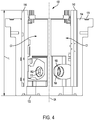
- the sensor head housing 104 houses an emitter module 140 (best seen in FIGS. 6 and 7 ) and a detector module 150 (best seen in FIG. 8 ).
- the components on the emitter module 140 and the detector module 150 can be held in chambers "C1" and "C2" that encloses each board, as seen in FIG. 5 .
- the first chamber "C1" receives the emitter module 140.
- the first chamber “C1” can be of cylindrical shape.
- the second chamber “C2” receives the detector module 150.
- the first chamber C1 and the second chamber C2 may be positioned symmetrically about the longitudinal axis "SA" of the sensor head 102 (e.g., with a vertical orientation).
- Each chamber “C1” and “C2” includes a cutout, and the sensor head housing 104 extending through the housing. These cutouts 156 allow electromagnetic radiation from an excitation source 158 (e.g., from an LED source) positioned on the emitter module 140 and an emission detector 194 (e.g., phototransistor) positioned on the detector module 150 to communicate with an analytical area outside the sensor head housing 104.
- an excitation source 158 e.g., from an LED source
- an emission detector 194 e.g., phototransistor
- the sensor head 102 also includes one or more temperature sensors that are able to measure the temperature of a water sample.
- the emitter module 140 and/or the detector module 150 may include one or more temperature sensors that extend into the sensor head housing 104.
- the excitation window 160 provides a path through a first wall "W1" for the electromagnetic radiation emitted by the excitation source 158.
- a second wall “W2” similarly defines an emission detector window 162 that provides a path through the second wall "W2" for electromagnetic radiation emitted by the sample to reach the emission detector 194.
- the excitation window 160 and/or the emission detector window 162 define a channel 164 extending through the sensor head housing 104.
- a focusing apparatus 166 may be positioned adjacent each window to prevent electromagnetic radiation from the excitation source 158 (e.g., directed toward the sample), or that emitted by the sample (e.g., toward the emission detector 194) from entering the channel 164.
- the focusing apparatus 166 can be a lens, mirror, prism or other optical elements known in the art for redirecting electromagnetic radiation.
- the focusing apparatus 166 e.g., ball lenses
- the focusing apparatus 166 is made of glass.
- a pair of ball lenses 168, 170 is positioned adjacent the excitation and emission detector 194 window.
- the focusing apparatus 166 e.g., ball lenses
- the focusing apparatus 166 is made of sapphire.
- the focusing apparatus 166 can be (e.g., made of suitable materials) to be substantially transparent to the excitation and/or emission wavelengths.
- the first ball lens 168 168 can be substantially transparent to electromagnetic radiation emitted by the excitation source 158 and the second ball lens 170 can be substantially transparent to electromagnetic radiation emitted by the sample.
- both the first and second ball lenses 168, 170 can be substantially transparent to electromagnetic radiation emitted by both the excitation source 158 and the sample.
- the focusing apparatus 166 can direct electromagnetic radiation from the excitation source 158 toward the sample and that from the sample toward the detector module 150. At the same time, the focusing apparatus 166 can prevent any electromagnetic radiation (e.g., from the excitation source 158 and the sample) from entering the channel 164 defined by the excitation window 160 and the emission detector 194 window.
- the excitation and emission detector windows 160, 162 also include a lens, prism or other material optically transparent to the emissions.
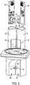
- the sensor head 102 includes a proximal end 172 and a distal end 174, between which extends the longitudinal axis "SA" and a length "L” of the sensor head 102. As shown in FIGS. 1 and 3 , in some embodiments the sensor head 102 is connected to the bottom surface 122 of the controller housing 112 at or near the proximal end 172 of the sensor head 102. The sensor head 102 may be positioned and oriented such that the longitudinal axis "SA" of the sensor head 102 forms an angle "A" with a longitudinal axis "CA” of the controller module 110.
- the sensor head 102 may be removably or fixedly attached to the controller housing 112 with a fastener (not shown).
- the fastener can include, but is not limited to, screws, bolts, and/or pins.
- the sensor head 102 may be fixedly bonded to the controller housing 112 by an adhesive or by welding.
- the sensor head 102 is secured with four screws that compress an O-ring positioned in a groove between the sensor head 102 and the controller module 110.
- the sensor head housing 104 may be integrally formed (e.g., molded) with the controller module 110.
- the sensor head 102 can also include part or all of a fastener that removably fastens a sample container to the sensor head 102.
- the fastener may comprise one or more pins positioned about the sensor head housing 104. Corresponding slots on the sample container receive the pins extending form the sensor head 102 housing. In some embodiments the pins and the slots form a bayonet fastener that secures the sample container about the sensor head 102 and also aligns the sample container in a preferred orientation (e.g., rotation, three-dimensional position) about the sensor head 102.
- Other fasteners e.g., screw threads, opposing pressure elements, etc.
- the sample container may engage with the sensor head 102 by a friction fit.
- the sensor head 102 also includes holes for inserting one or more temperature sensor covers.
- the temperature sensors (not shown) can sense the temperature of the water sample that can be used to correct concentration determination based on errors due to temperature effects.
- the sensor head 102 can be an immersible sensor head. In some cases, the sensor head 102 can be partly or wholly immersed in a sample. Accordingly, the sensor head housing 104, controller housing 112, and other components can be sealed (e.g., fluid resistant seals, O-rings and the like) prior to immersion.
- the excitation window 160 and emission detector window 162 may also be sealed with O-rings and the like. In some embodiments, the excitation window 160 and emission detector window 162 are sealed due to a pressure fit between the windows, channel 164, and the first and second ball lenses 168, 170 placed within the channel 164.
- fluorescence measurements can be taken by a fluorometer 100 by manually lowering the sensor head 102 into a water sample.
- a user can grasp the controller module 110 and temporarily dip the sensor head 102 into a liquid sample such that the sensor head 102 is partially or completely immersed in the sample and the sample occupies an analytical area near the sensor head 102 windows.
- the orientation of the attachment between the sensor head 102 and the controller module 110 can be set to provide the fluorometer 100 with a desired inclined position on the support surface.
- the sensor head 102 is connected to the controller module 110 such that the longitudinal axis "SA" of the sensor head 102 forms an angle "A" in the range between about 60 degrees and about 90 degrees with the longitudinal axis "CA” of the controller module 110.
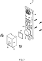
- FIGS. 6 and 7 show various views of an emitter module 140 according to some embodiments of the invention.
- the emitter module 140 (also shown in FIG. 2 as 320) can include a printed circuit board having an excitation source 158 and a reference photodetector 182 (best seen in FIG.13 ).
- the emitter module 140 can include an amplifier 184 and a connector for coupling the emitter module 140 with the controller board 114.
- the excitation source 158 can include a variety of possible elements.
- excitation source 158 may be a gas discharge lamp, a mercury lamp, a deuterium lamp, a metal vapor lamp, a light emitting diode (LED) or a plurality of LED lamps.
- the excitation source 158 may emit electromagnetic radiation in a number of possible spectrums depending upon the excitation element chosen and the spectrum desired.
- the excitation source 158 is an LED lamp, capable of emitting ultraviolet (UV) radiation having a wavelength from about 250 nanometers to about 310 nanometers.
- An excitation filter 188 is positioned in an excitation filter holder 190 to intercept electromagnetic radiation from the excitation source 158.
- the excitation filter 188 can filter the electromagnetic radiation from the excitation source 158 before it leaves the sensor head 102.
- the excitation filter holder 190 can define an aperture 192 for passage of electromagnetic radiation from the excitation source 158, via the excitation filter 188 and toward the sample.
- the shape of aperture 192 may be defined by forming it integrally within the excitation filter holder 190 or it may be defined by forming it via an assembly of components including the excitation filter holder 190.
- the excitation filter 188 can substantially transmit electromagnetic radiation from the excitation source 158. In some embodiments, the excitation filter 188 configured for transmitting electromagnetic radiation within a desired wavelength range toward the sample. Referring now to FIGS. 9 and 10 , the excitation source 158 can emit electromagnetic radiation at a desired wavelength or in a wavelength range. In the embodiment illustrated in FIG. 6 , the excitation source 158 emits electromagnetic radiation in the spectral range between about 250 nanometers and about 300 nanometers. For instance, if fluorescence of dipicolinic acid is to be measured, the excitation source 158 can emit electromagnetic radiation in the spectral range between about 260 nanometers and about 285 nanometers.
- an operator may enter (e.g., via the keypad 108) one or more wavelengths at which electromagnetic radiation is to be emitted by the excitation source 158.
- the controller 128 may then communicate with the emitter module 140 so that the excitation source 158 emits electromagnetic radiation at the wavelengths selected by the operator.
- the excitation filter 188 can substantially transmit at least a portion of the electromagnetic radiation in at least a portion of the excitation spectrum (e.g., excitation peak "e" shown in FIG. 9 ).
- the excitation filter 188 can have a transmittance "t1" of between about 50% and about 100% in the spectral range corresponding to excitation. In the illustrated embodiments shown in FIGS.
- the excitation filter 188 has a transmittance "t1" of about 75% in the spectral range of between about 250 nanometers and about 285 nanometers.
- the excitation filter 188 can have a transmittance "t1" of between about 50% and 100% in the spectral range of between about 150 nanometers and 380 nanometers, for excitation in the spectral range of between about 250 nanometers and about 300 nanometers.
- the filtered electromagnetic radiation can then be directed (e.g., by the focusing apparatus 166 shown in FIGS. 4 and 5 ) toward the sample to induce fluorescent emissions from the sample.
- FIG. 8 is a perspective view of a detector module 150 according to some embodiments of the invention.
- the detector module 150 can be used for detecting (e.g., measuring the intensity of) the fluorescence emitted by the sample.
- the detector module 150 generally includes a number of components, including an emission detector 194 positioned on a printed circuit board.
- the detector module 150 also includes an amplifier 184 and a temperature sensor.
- the emission detector 194 can be a photodiode.
- the emission detector 194 can be a phototransistor.
- the emission detector 194 can sense electromagnetic radiation emitted by the sample at a plurality of wavelengths. In one example, the emission detector 194 can sense electromagnetic radiation at wavelengths between about 400 nanometers and about 1500 nanometers.
- the sample emits fluorescence in the spectral range between about 400 nanometers and about 700 nanometers.
- the sample may emit discretely (e.g., discrete intensity peaks, "f1", “f2", “f3”, and "f4" shown in FIG. 9 ) at selected wavelengths (e.g., about 490 nanometers, about 550 nanometers, about 580 nanometers, and about 620 nanometers).
- the emission detector 194 can be sensitive to fluorescence emitted by the sample at such discrete wavelengths, and have sufficient linearity (e.g., measured signal linearly proportional to intensity of fluorescence.)
- An emission filter holder 196 positioned about the emission detector 194 supports one or more emission filters 198 for filtering undesirable electromagnetic radiation and transmitting the desired electromagnetic radiation to the emission detector 194.
- the emission filter 198 is a polycarbonate filter a thickness between about 1 millimeter and about 10 millimeters. In some embodiments, the thickness of the emission filter 198 can be between about 2 millimeters and about 4 millimeters.
- the emission filter 198 can be of any shape (square, rectangular, elliptical) and in the illustrated embodiment is of circular shape. Alternatively other filters (e.g., interference glass) filters can be used.
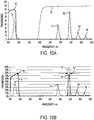
- the emission filter 198 can have a transmittance "t2" of between about 60% and about 100% in the spectral range corresponding to fluorescence emitted by the sample. In the embodiments shown in FIG. 10A , the emission filter 198 has a transmittance "t2" of about 87% in the spectral range between about 400 nanometers and about 650 nanometers, thereby substantially transmitting the fluorescence emitted by the sample toward the emission detector 194.
- the sensitivity of fluorescence measurements can be improved and any background signals from other components in chemical composition can be decreased by providing an interference filter as the emission filter 198.
- a narrow band interference filter is used as emission filter 198
- a short pass interference filter is used as the excitation filter 188.
- the short pass interference filter used as the excitation filter 188 can be FF01-300-SP made by Semrock Inc. (Lake Forest, Illinois) and has a transmittance "t3" as shown in FIG. 10B .
- the narrow band interference filter used as the emission filter 198 can be FF01-543-3 made by Semrock Inc. (Lake Forest, Illinois) and has a transmittance "t4" shown in FIG. 10B .
- the narrow band interference can have a bandwidth "b1".
- the bandwidth "bl" can correspond to the wavelength interval over which the narrow band interference filter substantially transmits (e.g., with a transmittance of at least 60%) the electromagnetic radiation emitted by the sample.
- the bandwidth of the narrow band interference filter can be between about 1 nanometer and 20 nanometers.
- the narrow band interference filter has a bandwidth between about 2 nanometers and about 10 nanometers.
- Such filters can block as much as 20 times any electromagnetic radiation from background components than other filters known in the art enabling an operator to measure concentrations of DPA lower than 0.1 parts per billion.
- the emitter module 140 can be oriented and positioned so that the amount of electromagnetic radiation from the excitation source 158 directed toward the detector module 150 (e.g., via the channel 164 defined by the excitation window 160 and the emission window) is reduced.
- the excitation filter holder 190 can be shaped and oriented to prevent electromagnetic radiation from the excitation source 158 from entering the detector module 150, thereby preventing inaccurate measurement of fluorescence emitted by the sample.
- the excitation filter holder 190 can permit passage of electromagnetic radiation (e.g., filtered by the excitation filter 188) through the aperture 192 and towards the sample such that the first beam path defines a trajectory of electromagnetic radiation from the excitation source 158 to the excitation filter 188, via the aperture 192 and toward the sample.
- the aperture 192 can be positioned asymmetrically relative to the first beam path such that the aperture 192 allows a first asymmetrical portion of the electromagnetic radiation in the first beam path to pass therethrough and the excitation filter holder 190 blocks passage of a corresponding second asymmetrical portion of the electromagnetic radiation in the first beam path.
- the blocked passage of the corresponding second asymmetrical portion of the electromagnetic radiation in the first beam path can reduce the amount of electromagnetic radiation oriented directly from the emitter module 140 to the detector module 150.
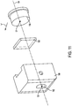
- the aperture 192 defined by the excitation filter holder 190 can be of a truncated circular shape, as shown in FIGS. 11 and 12A-12D .
- the excitation filter holder 190 can be of semi-circular shape.
- the aperture 192 can be of other asymmetric shapes (e.g., truncated ellipse, rectangle, triangular or square).
- the truncated circular shape can substantially direct the filtered electromagnetic radiation from the excitation source 158 toward the sample.
- the truncated circular shape has a first portion "b" and a second portion "c"
- the first beam path is from the excitation source 158 toward the sample, and the trajectory of the beam is from the excitation source 158 to the excitation filter 188.
- the first asymmetrical portion of the electromagnetic radiation corresponds to electromagnetic radiation directed toward the sample by portion "b", and the corresponding second asymmetric portion of the electromagnetic radiation blocked is that portion of the electromagnetic radiation from the excitation source 158 blocked by the portion "c".
- the excitation source 158 can be moved from its optical alignment (e.g., along an optical axis "OA" as seen in FIG. 11 ) with the aperture 192 to an asymmetric position.
- the geometric center "O1" of the excitation source 158, and the geometric center “O2" of the aperture 192 can be laterally offset with respect to each other from their alignment shown in FIG. 11 .
- the excitation source 158 is moved further toward the direction "a"
- nearly all the radiation emitted by the excitation source 158 can be directed toward the portion "b" of the aperture 192 and further toward the sample.
- the radiation directed toward portion "b" of the aperture 192 may then be directed by the focusing apparatus 166 toward the sample. Consequently, the amount of electromagnetic radiation reaching the detector module 150 can be reduced.
- the first asymmetrical portion of the electromagnetic radiation is that which is toward the sample via portion "b"
- the corresponding second asymmetrical portion may refer to any electromagnetic radiation not directed toward the portion "b" of the aperture 192.
- the corresponding second asymmetrical portions may equal zero, corresponding to a state where no electromagnetic radiation is directed in a direction other than a direction toward the sample.
- the sensitivity of the fluorometer 100 can be improved by reducing the intensity of stray electromagnetic radiation.
- One source of such stray electromagnetic radiation can be those that are reflected by internal surfaces of the excitation filter holder 190.
- Electromagnetic radiation from the excitation source 158 may reach the walls of the excitation filter holder 190 (via the excitation filter 188). The walls of the excitation filter holder 190 may reflect the electromagnetic radiation toward areas in the emitter module 140 that lead to reduced measurement sensitivity.
- a reference photodetector 182 may be placed on the emitter module 140 to monitor the intensity of the electromagnetic radiation emitted by the excitation source 158.
- the intensity of the electromagnetic radiation emitted by the excitation source 158 can be useful in determining the concentration of the sample.
- Stray electromagnetic radiation e.g., reflected by the excitation filter holder 190
- an attenuator 200 may be placed on a least a portion of the reference photodetector 182. The attenuator 200 can obstruct at least a portion of the reference photodetector 182.
- the attenuator 200 can provide spatially uniform attenuation of electromagnetic radiation emitted by the excitation source 158 over a surface area of the attenuator 200 such that the attenuator 200 helps prevent the reference photodetector 182 from being saturated with electromagnetic radiation.
- the attenuator 200 can include a layer of polytetrafluoroethylene (Teflon) coupled (e.g., bonded by an adhesive) to the emitter module 140.
- Teflon polytetrafluoroethylene
- the attenuator 200 can be made of stainless steel mesh.
- the attenuator 200 can be coupled to the emitter module 140 in any manner (e.g., with a fastener, adhesive, by welding, soldering, thermally-treating etc.).
- the thickness of the attenuator 200 can be between about 0.1 millimeter and 1 millimeter.
- the attenuator 200 can be a layer of Teflon of thickness of about 0.5 millimeters (20 mil).
- Embodiments of the invention are thus useful in many applications.
- Fluorometers according to some embodiments of the invention are suitable for bacterial spore detection by adding terbium chloride to microbial spore (e.g., bacterial spore, which may comprise dipicolinic acid).
- microbial spore e.g., bacterial spore, which may comprise dipicolinic acid.
- Sufficient dilution of the dipicolinic acid and terbium chloride solution may produce fluorescence intensity linearly proportional to the concentration, thereby enhancing the sensitivity of concentration and/or fluorescent measurement.
- Embodiments of the invention also provide enhanced sensitivity due in part to the immediate proximity of the sample to the excitation source and the emission detector.
- Embodiments of the invention facilitate low cost elimination of stray electromagnetic radiation, and improved measurement sensitivity. Better accuracy in measuring even low intensity fluorescence can facilitate measuring very low concentrations of product (e.g., parts per billion, ppb) and/or for measuring concentration
Applications Claiming Priority (3)
| Application Number | Priority Date | Filing Date | Title |
|---|---|---|---|
| US14/457,573 US9261459B1 (en) | 2014-08-12 | 2014-08-12 | Handheld fluorometer |
| EP15832275.0A EP3180601B1 (de) | 2014-08-12 | 2015-08-03 | Handfluorometer |
| PCT/US2015/043384 WO2016025205A1 (en) | 2014-08-12 | 2015-08-03 | Handheld fluorometer |
Related Parent Applications (1)
| Application Number | Title | Priority Date | Filing Date |
|---|---|---|---|
| EP15832275.0A Division EP3180601B1 (de) | 2014-08-12 | 2015-08-03 | Handfluorometer |
Publications (2)
| Publication Number | Publication Date |
|---|---|
| EP3719480A1 true EP3719480A1 (de) | 2020-10-07 |
| EP3719480B1 EP3719480B1 (de) | 2022-10-05 |
Family
ID=55275374
Family Applications (2)
| Application Number | Title | Priority Date | Filing Date |
|---|---|---|---|
| EP15832275.0A Active EP3180601B1 (de) | 2014-08-12 | 2015-08-03 | Handfluorometer |
| EP20169090.6A Active EP3719480B1 (de) | 2014-08-12 | 2015-08-03 | Ein fluorometer zur messung der fluoreszenz einer probe |
Family Applications Before (1)
| Application Number | Title | Priority Date | Filing Date |
|---|---|---|---|
| EP15832275.0A Active EP3180601B1 (de) | 2014-08-12 | 2015-08-03 | Handfluorometer |
Country Status (9)
| Country | Link |
|---|---|
| US (2) | US9261459B1 (de) |
| EP (2) | EP3180601B1 (de) |
| CN (2) | CN106716110B (de) |
| AU (2) | AU2015302108B2 (de) |
| CA (1) | CA2957685C (de) |
| ES (2) | ES2934968T3 (de) |
| MX (1) | MX369141B (de) |
| NZ (1) | NZ728774A (de) |
| WO (1) | WO2016025205A1 (de) |
Families Citing this family (10)
| Publication number | Priority date | Publication date | Assignee | Title |
|---|---|---|---|---|
| US11199490B2 (en) * | 2016-06-23 | 2021-12-14 | Biocomp Instruments Inc. | Flow cell and system for simultaneous measurement of absorbance and emission in a sample |
| WO2018039624A1 (en) | 2016-08-26 | 2018-03-01 | The Texas A&M University System | Hand-held synchronous scan spectrometer for in situ detection of pathogens and mineral deficiency in blood |
| US20180206475A1 (en) * | 2017-01-20 | 2018-07-26 | Mark A. Carter | Chemical application detection system and mobile visual sensing technology |
| US10630873B2 (en) * | 2017-07-27 | 2020-04-21 | Command Sight, Inc. | Animal-wearable first person view system |
| US11497581B2 (en) | 2018-11-05 | 2022-11-15 | Medivators Inc. | Endoscope cleaning and inspection system and method |
| WO2020096894A1 (en) * | 2018-11-05 | 2020-05-14 | Medivators Inc. | Endoscope fluorescence inspection device |
| EP3940374A4 (de) * | 2019-03-29 | 2022-12-14 | Daikin Industries, Ltd. | Verfahren zur inspektion eines formprodukts und verfahren zur herstellung eines formprodukts |
| EP3726217B1 (de) * | 2019-04-18 | 2023-06-28 | Elionova AG | Optimierung eines evaneszenz-biosensors |
| DE102019114522A1 (de) * | 2019-05-29 | 2020-12-03 | Valeo Siemens Eautomotive Germany Gmbh | Vorrichtung mit einer Stromschienenanordnung, einer Filtervorrichtung und einer Abdeckung, zugehöriges Herstellungsverfahren sowie Stromrichter und Antriebseinrichtung |
| USD897536S1 (en) * | 2019-06-19 | 2020-09-29 | Life Technologies Corporation | Fluorometer |
Citations (10)
| Publication number | Priority date | Publication date | Assignee | Title |
|---|---|---|---|---|
| US4802768A (en) * | 1986-04-11 | 1989-02-07 | Sclavo, Inc. | Two light source reference system for a fluorometer |
| US5208466A (en) * | 1991-10-08 | 1993-05-04 | Beckman Instruments, Inc. | Apparatus and method for aligning capillary column and detection optics |
| US7301158B1 (en) * | 2004-12-15 | 2007-11-27 | Turner Designs, Inc. | Method and apparatus for measuring active fluorescence |
| US20080252954A1 (en) * | 2005-06-02 | 2008-10-16 | Capitalbio Corporation | Laser Confocal Microarray Scanner |
| WO2009007888A1 (en) * | 2007-07-09 | 2009-01-15 | Koninklijke Philips Electronics N. V. | An opto-mechanical arrangement for providing optical access to a sample chamber |
| US20090046756A1 (en) * | 2005-06-03 | 2009-02-19 | Xianhua Wang | Optical Systems for Microarray Scanning |
| US7550746B2 (en) | 2006-06-01 | 2009-06-23 | Ecolab Inc. | UV fluorometric sensor and method for using the same |
| US20110127444A1 (en) * | 2009-11-30 | 2011-06-02 | Masatsugu Ozasa | Particle analyzing apparatus and particle imaging method |
| US20110246118A1 (en) * | 2010-03-31 | 2011-10-06 | Ecolab Usa Inc | Methods for Calibrating a Fluorometer |
| US8269193B2 (en) | 2010-03-31 | 2012-09-18 | Ecolab Usa Inc. | Handheld fluorometer and method of use |
Family Cites Families (27)
| Publication number | Priority date | Publication date | Assignee | Title |
|---|---|---|---|---|
| JPS5492232A (en) * | 1977-12-28 | 1979-07-21 | Canon Inc | Camera |
| US4783314A (en) | 1987-02-26 | 1988-11-08 | Nalco Chemical Company | Fluorescent tracers - chemical treatment monitors |
| US4977325A (en) * | 1989-07-12 | 1990-12-11 | P B Diagnostic Systems, Inc. | Optical read system and immunoassay method |
| ZA984976B (en) | 1997-06-11 | 1999-04-19 | Nalco Chemical Co | Solid-state fluorometer and methods of use therefore |
| US5876960A (en) | 1997-08-11 | 1999-03-02 | The United States Of America As Represented By The Secretary Of The Army | Bacterial spore detection and quantification methods |
| US6402986B1 (en) | 1999-07-16 | 2002-06-11 | The Trustees Of Boston University | Compositions and methods for luminescence lifetime comparison |
| EP2264439A3 (de) * | 1999-11-12 | 2011-01-19 | E.I. Du Pont De Nemours And Company | Fluorometer mit Lichtquelle mit geringer Wärmeerzeugung |
| US6369894B1 (en) | 2000-05-01 | 2002-04-09 | Nalco Chemical Company | Modular fluorometer |
| US6831745B2 (en) | 2001-01-23 | 2004-12-14 | University Of Washington | Optical immersion probe incorporating a spherical lens |
| WO2003023379A1 (en) | 2001-09-12 | 2003-03-20 | Apprise Technologies, Inc. | Multichannel fluorosensor |
| US7306930B2 (en) | 2001-11-30 | 2007-12-11 | California Institute Of Technology | Method bacterial endospore quantification using lanthanide dipicolinate luminescence |
| US6842243B2 (en) | 2001-12-10 | 2005-01-11 | Apprise Technologies, Inc. | Turbidity sensor |
| JP2005516213A (ja) | 2002-02-01 | 2005-06-02 | カリフォルニア インスティチュート オブ テクノロジー | 細菌胞子の分析方法および装置 |
| JP4208232B2 (ja) * | 2002-10-29 | 2009-01-14 | フジノン株式会社 | 投写レンズの異形絞り設置構造およびこれを備えた投写型画像表示装置 |
| US7563615B2 (en) | 2005-04-15 | 2009-07-21 | California Institute Of Technology | Apparatus and method for automated monitoring of airborne bacterial spores |
| US7611862B2 (en) | 2004-11-12 | 2009-11-03 | California Institute Of Technology | Method and apparatus for detecting and quantifying bacterial spores on a surface |
| US7375359B1 (en) * | 2003-05-22 | 2008-05-20 | Thermo Niton Analyzers Llc | Portable X-ray fluorescence instrument with tapered absorption collar |
| US7220382B2 (en) | 2003-07-31 | 2007-05-22 | Nalco Company | Use of disulfonated anthracenes as inert fluorescent tracers |
| US7095500B2 (en) | 2004-01-30 | 2006-08-22 | Nalco Company | Interchangeable tip-open cell fluorometer |
| US7179384B2 (en) | 2004-04-30 | 2007-02-20 | Nalco Company | Control of cooling water system using rate of consumption of fluorescent polymer |
| US20130224850A1 (en) | 2005-04-01 | 2013-08-29 | Ronald E. Meyers | Device and method for detecting bacterial endospores that are suspended in the atmosphere |
| US7916834B2 (en) * | 2007-02-12 | 2011-03-29 | Thermo Niton Analyzers Llc | Small spot X-ray fluorescence (XRF) analyzer |
| US8038947B2 (en) | 2007-04-09 | 2011-10-18 | University Of Maryland, Baltimore | Analyte sensor devices and holders, and methods and systems utilizing the same |
| DE202008009859U1 (de) * | 2007-12-21 | 2009-03-05 | Berthold Technologies Gmbh & Co. Kg | Vorrichtung zur wahlweisen Messung von insbesondere Lumineszenz- und/oder Fluoreszenzstrahlung |
| US8227766B2 (en) * | 2008-05-15 | 2012-07-24 | Navidea Biopharmaceuticals, Inc. | Hand-held probe for intra-operative detection of fluorescence labeled compounds and antibodies |
| GB2482423A (en) | 2010-07-31 | 2012-02-01 | Advanced Biomedical Ltd | A method for determining the effectiveness of a sterilization or disinfection process |
| JP5315381B2 (ja) * | 2011-06-17 | 2013-10-16 | 富士フイルム株式会社 | 蛍光検出装置、蛍光検出用の試料セルおよび蛍光検出方法 |
-
2014
- 2014-08-12 US US14/457,573 patent/US9261459B1/en active Active
-
2015
- 2015-08-03 EP EP15832275.0A patent/EP3180601B1/de active Active
- 2015-08-03 NZ NZ728774A patent/NZ728774A/en unknown
- 2015-08-03 CA CA2957685A patent/CA2957685C/en active Active
- 2015-08-03 MX MX2017001950A patent/MX369141B/es active IP Right Grant
- 2015-08-03 CN CN201580050497.0A patent/CN106716110B/zh active Active
- 2015-08-03 ES ES20169090T patent/ES2934968T3/es active Active
- 2015-08-03 AU AU2015302108A patent/AU2015302108B2/en active Active
- 2015-08-03 EP EP20169090.6A patent/EP3719480B1/de active Active
- 2015-08-03 CN CN202010919117.5A patent/CN112033946B/zh active Active
- 2015-08-03 ES ES15832275T patent/ES2806147T3/es active Active
- 2015-08-03 WO PCT/US2015/043384 patent/WO2016025205A1/en active Application Filing
- 2015-12-16 US US14/970,573 patent/US10254224B2/en active Active
-
2020
- 2020-04-30 AU AU2020202844A patent/AU2020202844B2/en active Active
Patent Citations (14)
| Publication number | Priority date | Publication date | Assignee | Title |
|---|---|---|---|---|
| US4802768A (en) * | 1986-04-11 | 1989-02-07 | Sclavo, Inc. | Two light source reference system for a fluorometer |
| US5208466A (en) * | 1991-10-08 | 1993-05-04 | Beckman Instruments, Inc. | Apparatus and method for aligning capillary column and detection optics |
| US7301158B1 (en) * | 2004-12-15 | 2007-11-27 | Turner Designs, Inc. | Method and apparatus for measuring active fluorescence |
| US20080252954A1 (en) * | 2005-06-02 | 2008-10-16 | Capitalbio Corporation | Laser Confocal Microarray Scanner |
| US20090046756A1 (en) * | 2005-06-03 | 2009-02-19 | Xianhua Wang | Optical Systems for Microarray Scanning |
| US7550746B2 (en) | 2006-06-01 | 2009-06-23 | Ecolab Inc. | UV fluorometric sensor and method for using the same |
| US7652267B2 (en) | 2006-06-01 | 2010-01-26 | Ecolab Inc. | UV fluorometric sensor and method for using the same |
| US7989780B2 (en) | 2006-06-01 | 2011-08-02 | Ecolab Inc. | UV fluorometric sensor and method for using the same |
| US8084756B2 (en) | 2006-06-01 | 2011-12-27 | Ecolab Inc. | UV fluorometric sensor and method for using the same |
| WO2009007888A1 (en) * | 2007-07-09 | 2009-01-15 | Koninklijke Philips Electronics N. V. | An opto-mechanical arrangement for providing optical access to a sample chamber |
| US20110127444A1 (en) * | 2009-11-30 | 2011-06-02 | Masatsugu Ozasa | Particle analyzing apparatus and particle imaging method |
| US20110246118A1 (en) * | 2010-03-31 | 2011-10-06 | Ecolab Usa Inc | Methods for Calibrating a Fluorometer |
| US8269193B2 (en) | 2010-03-31 | 2012-09-18 | Ecolab Usa Inc. | Handheld fluorometer and method of use |
| US8352207B2 (en) | 2010-03-31 | 2013-01-08 | Ecolab Usa Inc. | Methods for calibrating a fluorometer |
Also Published As
| Publication number | Publication date |
|---|---|
| EP3180601B1 (de) | 2020-04-15 |
| EP3719480B1 (de) | 2022-10-05 |
| CN106716110A (zh) | 2017-05-24 |
| US20160047746A1 (en) | 2016-02-18 |
| AU2015302108B2 (en) | 2020-02-06 |
| MX369141B (es) | 2019-10-30 |
| CN112033946A (zh) | 2020-12-04 |
| US20160097721A1 (en) | 2016-04-07 |
| ES2806147T3 (es) | 2021-02-16 |
| ES2934968T3 (es) | 2023-02-28 |
| AU2015302108A1 (en) | 2017-02-23 |
| WO2016025205A1 (en) | 2016-02-18 |
| AU2020202844A1 (en) | 2020-05-21 |
| US9261459B1 (en) | 2016-02-16 |
| EP3180601A4 (de) | 2018-05-02 |
| AU2020202844B2 (en) | 2021-05-27 |
| US10254224B2 (en) | 2019-04-09 |
| NZ728774A (en) | 2021-12-24 |
| EP3180601A1 (de) | 2017-06-21 |
| MX2017001950A (es) | 2017-08-14 |
| CA2957685C (en) | 2021-10-19 |
| CA2957685A1 (en) | 2016-02-18 |
| CN112033946B (zh) | 2023-11-14 |
| CN106716110B (zh) | 2020-09-15 |
Similar Documents
| Publication | Publication Date | Title |
|---|---|---|
| AU2020202844B2 (en) | Handheld fluorometer | |
| US8373140B2 (en) | Fluorometric sensor | |
| US8352207B2 (en) | Methods for calibrating a fluorometer | |
| US8269193B2 (en) | Handheld fluorometer and method of use | |
| CA2789971C (en) | Handheld optical measuring device and method of use |
Legal Events
| Date | Code | Title | Description |
|---|---|---|---|
| PUAI | Public reference made under article 153(3) epc to a published international application that has entered the european phase |
Free format text: ORIGINAL CODE: 0009012 |
|
| STAA | Information on the status of an ep patent application or granted ep patent |
Free format text: STATUS: THE APPLICATION HAS BEEN PUBLISHED |
|
| AC | Divisional application: reference to earlier application |
Ref document number: 3180601 Country of ref document: EP Kind code of ref document: P |
|
| AK | Designated contracting states |
Kind code of ref document: A1 Designated state(s): AL AT BE BG CH CY CZ DE DK EE ES FI FR GB GR HR HU IE IS IT LI LT LU LV MC MK MT NL NO PL PT RO RS SE SI SK SM TR |
|
| AX | Request for extension of the european patent |
Extension state: BA ME |
|
| RIN1 | Information on inventor provided before grant (corrected) |
Inventor name: FAWBUSH, STACY Inventor name: BAKKEN, AMANDA Inventor name: PILIPCHENKO, ANNA Inventor name: TOKHTUEV, EUGENE Inventor name: BOLDUC, JOHN WILHELM Inventor name: VALENSTEIN, JUSTIN SCOTT Inventor name: HUTCHISON, JEFFREY Inventor name: SKIRDA, ANATOLY |
|
| STAA | Information on the status of an ep patent application or granted ep patent |
Free format text: STATUS: REQUEST FOR EXAMINATION WAS MADE |
|
| 17P | Request for examination filed |
Effective date: 20210407 |
|
| RBV | Designated contracting states (corrected) |
Designated state(s): AL AT BE BG CH CY CZ DE DK EE ES FI FR GB GR HR HU IE IS IT LI LT LU LV MC MK MT NL NO PL PT RO RS SE SI SK SM TR |
|
| GRAP | Despatch of communication of intention to grant a patent |
Free format text: ORIGINAL CODE: EPIDOSNIGR1 |
|
| STAA | Information on the status of an ep patent application or granted ep patent |
Free format text: STATUS: GRANT OF PATENT IS INTENDED |
|
| INTG | Intention to grant announced |
Effective date: 20220504 |
|
| GRAS | Grant fee paid |
Free format text: ORIGINAL CODE: EPIDOSNIGR3 |
|
| GRAA | (expected) grant |
Free format text: ORIGINAL CODE: 0009210 |
|
| STAA | Information on the status of an ep patent application or granted ep patent |
Free format text: STATUS: THE PATENT HAS BEEN GRANTED |
|
| AC | Divisional application: reference to earlier application |
Ref document number: 3180601 Country of ref document: EP Kind code of ref document: P |
|
| AK | Designated contracting states |
Kind code of ref document: B1 Designated state(s): AL AT BE BG CH CY CZ DE DK EE ES FI FR GB GR HR HU IE IS IT LI LT LU LV MC MK MT NL NO PL PT RO RS SE SI SK SM TR |
|
| REG | Reference to a national code |
Ref country code: GB Ref legal event code: FG4D |
|
| REG | Reference to a national code |
Ref country code: CH Ref legal event code: EP |
|
| REG | Reference to a national code |
Ref country code: AT Ref legal event code: REF Ref document number: 1523032 Country of ref document: AT Kind code of ref document: T Effective date: 20221015 |
|
| REG | Reference to a national code |
Ref country code: IE Ref legal event code: FG4D |
|
| REG | Reference to a national code |
Ref country code: DE Ref legal event code: R096 Ref document number: 602015081122 Country of ref document: DE |
|
| REG | Reference to a national code |
Ref country code: LT Ref legal event code: MG9D |
|
| REG | Reference to a national code |
Ref country code: NL Ref legal event code: MP Effective date: 20221005 |
|
| REG | Reference to a national code |
Ref country code: ES Ref legal event code: FG2A Ref document number: 2934968 Country of ref document: ES Kind code of ref document: T3 Effective date: 20230228 |
|
| REG | Reference to a national code |
Ref country code: AT Ref legal event code: MK05 Ref document number: 1523032 Country of ref document: AT Kind code of ref document: T Effective date: 20221005 |
|
| PG25 | Lapsed in a contracting state [announced via postgrant information from national office to epo] |
Ref country code: NL Free format text: LAPSE BECAUSE OF FAILURE TO SUBMIT A TRANSLATION OF THE DESCRIPTION OR TO PAY THE FEE WITHIN THE PRESCRIBED TIME-LIMIT Effective date: 20221005 |
|
| PG25 | Lapsed in a contracting state [announced via postgrant information from national office to epo] |
Ref country code: SE Free format text: LAPSE BECAUSE OF FAILURE TO SUBMIT A TRANSLATION OF THE DESCRIPTION OR TO PAY THE FEE WITHIN THE PRESCRIBED TIME-LIMIT Effective date: 20221005 Ref country code: PT Free format text: LAPSE BECAUSE OF FAILURE TO SUBMIT A TRANSLATION OF THE DESCRIPTION OR TO PAY THE FEE WITHIN THE PRESCRIBED TIME-LIMIT Effective date: 20230206 Ref country code: NO Free format text: LAPSE BECAUSE OF FAILURE TO SUBMIT A TRANSLATION OF THE DESCRIPTION OR TO PAY THE FEE WITHIN THE PRESCRIBED TIME-LIMIT Effective date: 20230105 Ref country code: LT Free format text: LAPSE BECAUSE OF FAILURE TO SUBMIT A TRANSLATION OF THE DESCRIPTION OR TO PAY THE FEE WITHIN THE PRESCRIBED TIME-LIMIT Effective date: 20221005 Ref country code: FI Free format text: LAPSE BECAUSE OF FAILURE TO SUBMIT A TRANSLATION OF THE DESCRIPTION OR TO PAY THE FEE WITHIN THE PRESCRIBED TIME-LIMIT Effective date: 20221005 Ref country code: AT Free format text: LAPSE BECAUSE OF FAILURE TO SUBMIT A TRANSLATION OF THE DESCRIPTION OR TO PAY THE FEE WITHIN THE PRESCRIBED TIME-LIMIT Effective date: 20221005 |
|
| PG25 | Lapsed in a contracting state [announced via postgrant information from national office to epo] |
Ref country code: RS Free format text: LAPSE BECAUSE OF FAILURE TO SUBMIT A TRANSLATION OF THE DESCRIPTION OR TO PAY THE FEE WITHIN THE PRESCRIBED TIME-LIMIT Effective date: 20221005 Ref country code: PL Free format text: LAPSE BECAUSE OF FAILURE TO SUBMIT A TRANSLATION OF THE DESCRIPTION OR TO PAY THE FEE WITHIN THE PRESCRIBED TIME-LIMIT Effective date: 20221005 Ref country code: LV Free format text: LAPSE BECAUSE OF FAILURE TO SUBMIT A TRANSLATION OF THE DESCRIPTION OR TO PAY THE FEE WITHIN THE PRESCRIBED TIME-LIMIT Effective date: 20221005 Ref country code: IS Free format text: LAPSE BECAUSE OF FAILURE TO SUBMIT A TRANSLATION OF THE DESCRIPTION OR TO PAY THE FEE WITHIN THE PRESCRIBED TIME-LIMIT Effective date: 20230205 Ref country code: HR Free format text: LAPSE BECAUSE OF FAILURE TO SUBMIT A TRANSLATION OF THE DESCRIPTION OR TO PAY THE FEE WITHIN THE PRESCRIBED TIME-LIMIT Effective date: 20221005 Ref country code: GR Free format text: LAPSE BECAUSE OF FAILURE TO SUBMIT A TRANSLATION OF THE DESCRIPTION OR TO PAY THE FEE WITHIN THE PRESCRIBED TIME-LIMIT Effective date: 20230106 |
|
| REG | Reference to a national code |
Ref country code: DE Ref legal event code: R097 Ref document number: 602015081122 Country of ref document: DE |
|
| PG25 | Lapsed in a contracting state [announced via postgrant information from national office to epo] |
Ref country code: SM Free format text: LAPSE BECAUSE OF FAILURE TO SUBMIT A TRANSLATION OF THE DESCRIPTION OR TO PAY THE FEE WITHIN THE PRESCRIBED TIME-LIMIT Effective date: 20221005 Ref country code: RO Free format text: LAPSE BECAUSE OF FAILURE TO SUBMIT A TRANSLATION OF THE DESCRIPTION OR TO PAY THE FEE WITHIN THE PRESCRIBED TIME-LIMIT Effective date: 20221005 Ref country code: EE Free format text: LAPSE BECAUSE OF FAILURE TO SUBMIT A TRANSLATION OF THE DESCRIPTION OR TO PAY THE FEE WITHIN THE PRESCRIBED TIME-LIMIT Effective date: 20221005 Ref country code: DK Free format text: LAPSE BECAUSE OF FAILURE TO SUBMIT A TRANSLATION OF THE DESCRIPTION OR TO PAY THE FEE WITHIN THE PRESCRIBED TIME-LIMIT Effective date: 20221005 Ref country code: CZ Free format text: LAPSE BECAUSE OF FAILURE TO SUBMIT A TRANSLATION OF THE DESCRIPTION OR TO PAY THE FEE WITHIN THE PRESCRIBED TIME-LIMIT Effective date: 20221005 |
|
| PGFP | Annual fee paid to national office [announced via postgrant information from national office to epo] |
Ref country code: FR Payment date: 20230608 Year of fee payment: 9 |
|
| PLBE | No opposition filed within time limit |
Free format text: ORIGINAL CODE: 0009261 |
|
| STAA | Information on the status of an ep patent application or granted ep patent |
Free format text: STATUS: NO OPPOSITION FILED WITHIN TIME LIMIT |
|
| PG25 | Lapsed in a contracting state [announced via postgrant information from national office to epo] |
Ref country code: SK Free format text: LAPSE BECAUSE OF FAILURE TO SUBMIT A TRANSLATION OF THE DESCRIPTION OR TO PAY THE FEE WITHIN THE PRESCRIBED TIME-LIMIT Effective date: 20221005 Ref country code: AL Free format text: LAPSE BECAUSE OF FAILURE TO SUBMIT A TRANSLATION OF THE DESCRIPTION OR TO PAY THE FEE WITHIN THE PRESCRIBED TIME-LIMIT Effective date: 20221005 |
|
| 26N | No opposition filed |
Effective date: 20230706 |
|
| PGFP | Annual fee paid to national office [announced via postgrant information from national office to epo] |
Ref country code: IT Payment date: 20230711 Year of fee payment: 9 Ref country code: GB Payment date: 20230615 Year of fee payment: 9 Ref country code: ES Payment date: 20230908 Year of fee payment: 9 |
|
| PG25 | Lapsed in a contracting state [announced via postgrant information from national office to epo] |
Ref country code: SI Free format text: LAPSE BECAUSE OF FAILURE TO SUBMIT A TRANSLATION OF THE DESCRIPTION OR TO PAY THE FEE WITHIN THE PRESCRIBED TIME-LIMIT Effective date: 20221005 |
|
| PGFP | Annual fee paid to national office [announced via postgrant information from national office to epo] |
Ref country code: DE Payment date: 20230607 Year of fee payment: 9 |
|
| PG25 | Lapsed in a contracting state [announced via postgrant information from national office to epo] |
Ref country code: MC Free format text: LAPSE BECAUSE OF FAILURE TO SUBMIT A TRANSLATION OF THE DESCRIPTION OR TO PAY THE FEE WITHIN THE PRESCRIBED TIME-LIMIT Effective date: 20221005 |
|
| REG | Reference to a national code |
Ref country code: CH Ref legal event code: PL |
|
| PG25 | Lapsed in a contracting state [announced via postgrant information from national office to epo] |
Ref country code: MC Free format text: LAPSE BECAUSE OF FAILURE TO SUBMIT A TRANSLATION OF THE DESCRIPTION OR TO PAY THE FEE WITHIN THE PRESCRIBED TIME-LIMIT Effective date: 20221005 |
|
| PG25 | Lapsed in a contracting state [announced via postgrant information from national office to epo] |
Ref country code: LU Free format text: LAPSE BECAUSE OF NON-PAYMENT OF DUE FEES Effective date: 20230803 |
|
| PG25 | Lapsed in a contracting state [announced via postgrant information from national office to epo] |
Ref country code: LU Free format text: LAPSE BECAUSE OF NON-PAYMENT OF DUE FEES Effective date: 20230803 Ref country code: CH Free format text: LAPSE BECAUSE OF NON-PAYMENT OF DUE FEES Effective date: 20230831 |