EP3719476B1 - Rohrleitung mit einer messvorrichtung zur erfassung von partikeln und vorrichtung zur übermittlung von daten aus einer rohrleitung - Google Patents
Rohrleitung mit einer messvorrichtung zur erfassung von partikeln und vorrichtung zur übermittlung von daten aus einer rohrleitung Download PDFInfo
- Publication number
- EP3719476B1 EP3719476B1 EP20167758.0A EP20167758A EP3719476B1 EP 3719476 B1 EP3719476 B1 EP 3719476B1 EP 20167758 A EP20167758 A EP 20167758A EP 3719476 B1 EP3719476 B1 EP 3719476B1
- Authority
- EP
- European Patent Office
- Prior art keywords
- detection unit
- pipeline
- particles
- unit
- designed
- Prior art date
- Legal status (The legal status is an assumption and is not a legal conclusion. Google has not performed a legal analysis and makes no representation as to the accuracy of the status listed.)
- Active
Links
Images
Classifications
-
- G—PHYSICS
- G01—MEASURING; TESTING
- G01N—INVESTIGATING OR ANALYSING MATERIALS BY DETERMINING THEIR CHEMICAL OR PHYSICAL PROPERTIES
- G01N15/00—Investigating characteristics of particles; Investigating permeability, pore-volume or surface-area of porous materials
- G01N15/06—Investigating concentration of particle suspensions
-
- G—PHYSICS
- G01—MEASURING; TESTING
- G01N—INVESTIGATING OR ANALYSING MATERIALS BY DETERMINING THEIR CHEMICAL OR PHYSICAL PROPERTIES
- G01N15/00—Investigating characteristics of particles; Investigating permeability, pore-volume or surface-area of porous materials
- G01N15/10—Investigating individual particles
- G01N15/14—Optical investigation techniques, e.g. flow cytometry
- G01N15/1429—Signal processing
- G01N15/1433—Signal processing using image recognition
-
- G—PHYSICS
- G01—MEASURING; TESTING
- G01N—INVESTIGATING OR ANALYSING MATERIALS BY DETERMINING THEIR CHEMICAL OR PHYSICAL PROPERTIES
- G01N15/00—Investigating characteristics of particles; Investigating permeability, pore-volume or surface-area of porous materials
- G01N15/10—Investigating individual particles
- G01N15/14—Optical investigation techniques, e.g. flow cytometry
- G01N15/1456—Optical investigation techniques, e.g. flow cytometry without spatial resolution of the texture or inner structure of the particle, e.g. processing of pulse signals
- G01N15/1459—Optical investigation techniques, e.g. flow cytometry without spatial resolution of the texture or inner structure of the particle, e.g. processing of pulse signals the analysis being performed on a sample stream
-
- G—PHYSICS
- G01—MEASURING; TESTING
- G01N—INVESTIGATING OR ANALYSING MATERIALS BY DETERMINING THEIR CHEMICAL OR PHYSICAL PROPERTIES
- G01N15/00—Investigating characteristics of particles; Investigating permeability, pore-volume or surface-area of porous materials
- G01N15/10—Investigating individual particles
- G01N15/14—Optical investigation techniques, e.g. flow cytometry
- G01N15/1468—Optical investigation techniques, e.g. flow cytometry with spatial resolution of the texture or inner structure of the particle
- G01N15/147—Optical investigation techniques, e.g. flow cytometry with spatial resolution of the texture or inner structure of the particle the analysis being performed on a sample stream
-
- G—PHYSICS
- G01—MEASURING; TESTING
- G01N—INVESTIGATING OR ANALYSING MATERIALS BY DETERMINING THEIR CHEMICAL OR PHYSICAL PROPERTIES
- G01N33/00—Investigating or analysing materials by specific methods not covered by groups G01N1/00 - G01N31/00
- G01N33/18—Water
- G01N33/1826—Organic contamination in water
-
- G—PHYSICS
- G01—MEASURING; TESTING
- G01N—INVESTIGATING OR ANALYSING MATERIALS BY DETERMINING THEIR CHEMICAL OR PHYSICAL PROPERTIES
- G01N15/00—Investigating characteristics of particles; Investigating permeability, pore-volume or surface-area of porous materials
- G01N15/06—Investigating concentration of particle suspensions
- G01N15/075—Investigating concentration of particle suspensions by optical means
-
- G—PHYSICS
- G01—MEASURING; TESTING
- G01N—INVESTIGATING OR ANALYSING MATERIALS BY DETERMINING THEIR CHEMICAL OR PHYSICAL PROPERTIES
- G01N15/00—Investigating characteristics of particles; Investigating permeability, pore-volume or surface-area of porous materials
- G01N15/01—Investigating characteristics of particles; Investigating permeability, pore-volume or surface-area of porous materials specially adapted for biological cells, e.g. blood cells
- G01N2015/019—Biological contaminants; Fouling
-
- G—PHYSICS
- G01—MEASURING; TESTING
- G01N—INVESTIGATING OR ANALYSING MATERIALS BY DETERMINING THEIR CHEMICAL OR PHYSICAL PROPERTIES
- G01N15/00—Investigating characteristics of particles; Investigating permeability, pore-volume or surface-area of porous materials
- G01N15/06—Investigating concentration of particle suspensions
- G01N2015/0687—Investigating concentration of particle suspensions in solutions, e.g. non volatile residue
-
- G—PHYSICS
- G01—MEASURING; TESTING
- G01N—INVESTIGATING OR ANALYSING MATERIALS BY DETERMINING THEIR CHEMICAL OR PHYSICAL PROPERTIES
- G01N15/00—Investigating characteristics of particles; Investigating permeability, pore-volume or surface-area of porous materials
- G01N15/10—Investigating individual particles
- G01N15/14—Optical investigation techniques, e.g. flow cytometry
- G01N2015/1486—Counting the particles
Definitions
- the invention relates to a pipeline with a measuring device, in particular a sensor unit, for detecting particles in a pipeline. Furthermore, the invention relates to a device for transmitting data from a pipeline with such a measuring device.
- Fluid transport systems in particular pipeline systems, such as water supply systems and/or drinking water systems, supply drinking water to a large number of residential units on a daily basis. Depending on different, harmful particles in drinking water, people can become ill.
- Measuring devices are known from the prior art that require sampling to test the water and/or drinking water quality. For sampling, a water supply must be shut off and the pipeline opened at a specific point for sampling. Other measuring devices are provided in verified laboratories (according to the Drinking Water Protection Ordinance), which also require sampling to test the water and/or drinking water quality. The sample is sent to the laboratory, which uses suitable measuring devices to check the water and/or drinking water quality.
- devices and methods for detecting particles in a fluid from the WO 2010/051842 A1 , the WO 2018/001627 A1 , the U.S. 2017/219550 A1 and the U.S. 2017/242234 A1 known.
- the invention is based on the object of specifying a measuring device for detecting particles in a pipeline that is improved over the prior art.
- the object is achieved according to the invention by the features specified in claim 1.
- the object is achieved by the features specified in claim 12.
- the measuring device for detecting particles in a pipeline comprises at least one detection unit, which is arranged in a pipe interior of the pipeline, wherein the pipe interior has a medium, such as water and/or drinking water, and/or a medium can flow through it, the detection unit is designed to detect at least one occurrence of different particles in the medium.
- the interior of the tube is filled with a medium such as water and/or drinking water.
- a medium such as water and/or drinking water, can flow through the interior of the pipe in order to forward the medium.
- the measuring device is partially or completely integrated in the pipeline, in particular fixed in the interior of the pipe.
- the pipeline is part of a fluid transport system, such as a water supply system.
- the water supply system such as a water supply installation, provides water and/or drinking water for at least one residential unit, for example an apartment or house.
- the pipeline itself can be a fluid transport system.
- the detection unit is a measuring device, for example.
- the measuring device is designed to measure the medium, such as water and/or drinking water, continuously and/or at definable time intervals check for harmful particles.
- the medium such as water and/or drinking water
- particles in particular harmful foreign substances, can be detected early in the medium.
- the detection unit includes, for example, a control unit, by means of which the detection unit can be programmed.
- the detection unit can be controlled from the outside, for example adjustable, configurable.
- the registration unit can also be set or configured in the factory.
- the registration unit can also be set or configured after installation in the pipeline.
- the registration unit does not have to be removed from the pipeline to adjust it.
- the detection unit has, for example, a number of interfaces, such as communication interfaces, in particular wireless communication interfaces.
- the registration unit can be connected to a central server via one or more interfaces.
- the detection unit can be connected to a user's mobile device via one or more interfaces.
- the interior of the tube can be checked at any time for particles that are harmful to health or for other particles to be tested, with time-consuming, conventional sampling being no longer necessary.
- the time and cost involved in checking the medium are reduced.
- a tendency towards an increase in a particle concentration of harmful particles can be identified at an early stage.
- the detection unit is detachably fixed in the pipe interior, for example for maintenance work.
- data is transmitted wirelessly.
- the detection unit is designed to communicate with stationary or mobile data processing units and/or data collectors.
- the registration unit has a number of interfaces. By arranging the detection unit directly in the pipe interior, this can be continuously monitored.
- the acquisition unit is designed, for example, to acquire data on the state of the medium at definable time intervals. That in the pipeline of a water supply system Transported medium can be checked for hygiene in an uncomplicated manner, in particular compared to the prior art.
- the measuring device is arranged and mounted, for example screwed, for example as a mounting module at a suitable medium flow point or medium standing point within the pipeline, such as a water pipe.
- the detection unit is a sensor unit, for example. Since the detection unit is arranged and installed within the pipeline, no additional and time-consuming sampling is required.
- the detection unit checks the medium, for example while it is flowing through the pipeline or is in the pipeline, to determine whether dangerous and/or harmful biological particles such as legionella are present in the medium, in particular water.
- the detection unit is designed to classify and quantify biological particles in the water and/or drinking water.
- biological particles are understood to mean fungi and bacteria, such as coliform bacteria (Escherichia coli, also E. coli for short), legionella or other harmful particles and/or pests.
- coliform bacteria Esscherichia coli, also E. coli for short
- legionella other harmful particles and/or pests.
- particles carried along in the medium can be detected by the detection unit.
- the detection unit is designed to classify particle types.
- the detection unit is designed to determine a particle proportion (volume proportion), a particle concentration (volume concentration), a volume ratio, for example in percent by volume in relation to a volume of the medium and/or a particle density and/or a mass proportion.
- the detection unit is configured to use the so-called colony-forming unit (CFU for short) to quantify the particles.
- CFU colony-forming unit
- Limit and reference values for example for microbiological parameters, are listed in the Drinking Water Ordinance (TrinkwV).
- the detection unit is configured to provide a statistical distribution of the particles in the medium detect.
- the detection unit includes an evaluation unit.
- the evaluation unit is embedded in the detection unit in the form of evaluation electronics, comprising software and algorithms.
- conventional steps such as sealing off the pipeline and/or a medium supply, removal of the medium, loading of a test device can be omitted.
- the detection unit which is arranged in the pipeline and is integrated, for example, is designed to check the medium directly when activated to carry out a check. Data about the medium can therefore be continuously recorded and transmitted in real time. This leads to a quick result with little time expenditure compared to conventional measures. "Online monitoring and data transmission" is also possible.
- the detection unit is integrated into a network, such as a communication network, and can communicate with external and/or central servers and devices via at least one communication interface. For example, it is possible to transmit data that has been purely recorded and not yet evaluated and/or data that has already been determined, i.e. evaluated, by the recording unit, in particular the evaluation unit integrated in the recording unit.
- the data is transmitted to a data processing unit, such as a user's mobile device, and/or to a central server, to a cloud and/or to a laboratory.
- the detection unit sends the data when the detection unit receives a request sent by the central server and/or the external device via a wireless communication interface.
- the data is provided with a time stamp for further time-dependent analysis and statistical processing of the data.
- the detection unit is designed so that a liquid medium flows through it.
- the detection unit is designed to stand in the medium.
- the Detection unit essentially circular.
- a dimension, such as a diameter, of the sensing unit corresponds to a cross-section of the pipeline.
- Detachable fixing elements are arranged on the outer circumference of the detection unit. Fixing points corresponding to the detachable fixing elements of the detection unit are formed in the interior of the pipe.
- the detection unit is ring-shaped.
- the detection unit includes one or more openings through which the medium can flow.
- the detection unit is designed to be smaller than the cross section of the pipeline, for example.
- the detection unit is attached to an inner wall section of the pipeline.
- the detection unit is detachably fixed to the inner wall section.
- the detection unit is connected to the interior of the pipe in a material, non-positive and/or positive manner.
- a further possible embodiment provides that the detection unit is arranged in a riser section or a dead pipe section of the pipeline.
- the detection unit includes a filter unit which is designed to provide the particles to be detected with a fluorescent marking.
- the detection unit is designed to detect fluorescent particles.
- the detection unit includes a plurality of particles, for example suitable antibodies, which react with different particles.
- the particles can be excited by the particles, so that the particles fluoresce.
- a chemical reaction between particle and antibody thus causes a fluorescence that can be detected by the detection unit.
- biofluorescence can be detected by the detection unit.
- the detection unit comprises at least one camera unit.
- the camera unit is designed to capture fluorescent particles.
- the camera unit is configured to capture the fluorescent particles in the so-called VIS range.
- the detection unit comprises at least one filter unit which is designed to provide particles to be detected with a fluorescent marking.
- a fluorescent marking For example, special particles such as antibodies are arranged in the filter unit, which cause the particularly harmful particles to fluoresce.
- the filter unit is designed so that the medium flows through it and the harmful particles carried along in the medium are provided with a fluorescent marking.
- the camera unit and the filter unit are designed in the form of a measuring transducer.
- the detection unit includes a measuring transducer and evaluation electronics with software.
- the detection unit is at least partially detachably fixed in the interior of the pipe.
- maintenance work, repair work and an exchange of components integrated in the detection unit can be carried out in a simple manner.
- the filter unit is arranged in a secondary path of the pipeline, in particular a media flow, with the secondary path being able to be sealed off from the medium for the purpose of maintenance work, replacement and/or cleaning of the filter unit.
- the camera unit can be removed at any time for the purpose of maintenance work and/or cleaning.
- the detection unit is designed using pattern recognition and/or pattern matching and/or an algorithm to determine the occurrence of particles and/or a particle concentration and/or a particle density.
- the camera unit includes camera software.
- the camera unit is coupled to an evaluation unit.
- the particles are quantified by determining a surface (determined by integration) that is covered by particles in the camera image. Subsequently, the recorded data on the particle-covered surface area are compared to the total recorded surface area inside the tube.
- the camera software and/or the evaluation unit works, for example, with what is known as pattern matching or a learning and/or analytical algorithm in order to classify and quantify the particles.
- a learning process can be carried out in order to configure the algorithm with regard to a classification.
- an analytical algorithm is used, with dark and non-dark areas in the medium being determined, for example.
- the detection unit is designed to transmit determined data to a data processing unit.
- the recording unit includes interfaces for wireless transmission of the recorded data.
- the detection unit is integrated into a network and continuously supplies data on possible water and/or drinking water contamination, which can then be called up by a customer, for example, using application software or another evaluation platform.
- the customer is the operator of the water supply system. If increased water and/or drinking water contamination by harmful particles is detected, the detection unit can output information that the medium and/or the pipeline should be flushed or cleaned in some other way.
- the data determined can also be transmitted to an accredited laboratory in order, for example, to carry out a correlation between the laboratory result and the data determined using the recording unit.
- the invention relates to a device for transmitting data from a pipeline, comprising at least one measuring device according to the preceding description, and at least one data processing unit coupled and/or capable of being coupled to the measuring device, such as a central server or a mobile terminal device, with the measuring device detecting Data and / or data determined wirelessly transmitted to the data processing unit.
- the measuring device transmits recorded data and/or ascertained data continuously and/or at definable time intervals to the data processing unit.
- the invention relates to a pipeline with a pipe interior and a medium located in the pipe interior, wherein at least one measuring device according to the above description is arranged in the pipe interior.
- the interior of the pipe can be monitored as quickly, effectively and easily as possible.
- figure 1 shows schematically an embodiment of a measuring device 1 for detecting particles P in a pipeline 2, for example a pipeline system, in particular a drinking water system.
- the pipeline 2 is, for example, part of a fluid transport system FT, in particular a water transport system.
- the measuring device 1 comprises at least one detection unit 3, which is arranged in a tube interior 2.1.
- the pipeline section shown is, for example, a riser section or a dead pipe section of the pipeline 2.
- the detection unit 3 is designed, for example, as an electronic measuring device.
- the detection unit 3 is, for example, a stationary measuring device in the pipeline 2 .
- the interior of the tube 2.1 has a medium M.
- the medium M is, for example, water and/or drinking water.
- the medium M flows through the tube interior 2.1.
- the medium M is in pipeline 2.
- the detection unit 3 is designed to detect at least one occurrence of different particles P, in particular particles that are harmful to health, in the medium M.
- the measuring device 1 is designed as a stationary assembly module in the pipeline 2 and includes a housing 3.1 which surrounds and encapsulates the detection unit 3.
- the housing 3.1 can be designed in one or more parts.
- the housing 3.1 is designed to be permeable to the medium.
- the detection unit 3 is designed to classify and quantify biological particles P in the water and/or drinking water.
- biological particles P include fungi and bacteria, such as E. coli (Escherichia coli, E.coli for short), legionella or other harmful particles and/or pests.
- E. coli Erscherichia coli, E.coli for short
- legionella bacterium
- particles P carried along in the medium M can be detected by the detection unit 3 .
- the detection unit 3 is designed to classify particle types.
- the detection unit 3 is designed to record a particle proportion (volume proportion), a particle concentration (volume concentration), a volume ratio, for example in percent by volume (vol%) in relation to a volume of the medium M and/or a particle density and/or a mass proportion (mass -%) to determine.
- the detection unit 3 is designed, for example, for a liquid medium M to flow through. Alternatively or additionally, the detection unit 3 is designed to be in the medium M.
- the detection unit 3 is fastened or detachably fastened to an inner wall section 2.2 of the pipeline 2, for example.
- the housing 3.1 is fixed to the inner wall section 2.2.
- the detection unit 3 is designed to be smaller than the cross section of the pipeline 2, for example.
- a dimension, such as a diameter, of the detection unit 3 corresponds to the cross section of the pipeline 2.
- the housing 3.1 can, for example, be made smaller than the cross section of the pipeline 2 or have a dimension that corresponds to the dimension of the pipeline 2, in particular in cross section .
- the housing 3.1 includes fixing elements 3.2.
- the fixing elements 3.2 are, for example, screw elements, rivet elements, clips or other locking elements.
- the fixing elements 3.2 are materially bonded connection elements.
- the fixing elements 3.2 are welding or soldering elements.
- the detection unit 3 includes a filter unit 6, which is designed to provide the particles P to be detected with a fluorescent marking.
- the detection unit 3 is designed to detect fluorescent particles P.
- the detection unit 3 comprises a plurality of particles, for example suitable antibodies which can react with different particles P.
- the particles P can be excited by the particles, so that the particles P fluoresce.
- a chemical reaction between particle P and particle thus causes a fluorescence that can be detected by the detection unit 3 .
- a biofluorescence can be detected by the detection unit 3 .
- the detection unit 3 comprises, for example, a receiving device, not shown in detail here, through which the medium M can flow.
- the detection unit 3 includes a sensor, for example.
- the detection unit 3 is designed to determine the occurrence of particles P and/or a particle concentration and/or a particle density using pattern recognition and/or a pattern comparison and/or an algorithm.
- the detection unit 3 includes, for example, an evaluation unit 7.
- the evaluation unit 7 is embedded in the detection unit 3 in the form of evaluation electronics, including software and algorithms.
- recorded data is transmitted wirelessly.
- the detection unit 3 is designed to communicate with stationary or mobile data processing units 4 .
- the detection unit 3 has a number of interfaces, in particular communication interfaces KS.
- Data determined and/or recorded by means of the recording unit 3 can be transmitted to customers via the data processing unit 4 .
- the acquisition unit 3 is set up to evaluate acquired data itself and to transmit this as ascertained data.
- the detection unit 3 also transmits data that has been purely detected and not evaluated.
- the detection unit 3 is integrated into a network and continuously supplies data about possible water and/or drinking water contamination, which can then be called up by a customer, for example, using application software or another evaluation platform.
- the customer is the operator of the water supply system.
- the detection unit 3 can output information that flushing or other cleaning of the medium M and/or the pipeline 2 should be initiated.
- the determined and/or recorded data can also be transmitted to an accredited laboratory in order, for example, to carry out a correlation between the laboratory result and the data determined using the recording unit 3 .
- the data processing unit 4 is, for example, a user's mobile terminal device or a central server.
- the data processing unit 4 is a computing unit, for example.
- the data processing unit 4 is a so-called cloud storage space, for example.
- the data processing unit 4 is set up to receive data from the detection unit 3 with the detection unit 3, for example via a wireless network, such as a global network.
- the measuring device 1 is set up to acquire data directly and to transmit this via the communication interface KS.
- the communication interface KS is designed as a radio interface.
- the communication interface KS is designed to connect the detection unit 3 to the data processing unit 4 .
- the data is transmitted to the data processing unit 4 so that a user and/or a customer receives up-to-date information about the medium M in a timely manner.
- the data is transmitted to the data processing unit 4 so that the data can be recorded and checked by a laboratory, for example.
- the detection unit 3 can include a control unit. Alternatively, a separate control unit (not shown in detail) can be provided in the measuring device 1 .
- the detection unit 3 and the control unit are data-related coupled with each other.
- the measuring device 1 and/or the detection unit 3 can include a memory (not shown) for storing detected and/or determined data.
- the detection unit 3 can be controlled via the control unit.
- the detection unit 3 can be configured via the control unit.
- a communication link KV can be set up or set up between the detection unit 3 and the data processing unit 4 for data transmission.
- the communication connection KV takes place via one or more communication interfaces KS.
- the housing 3.1 surrounds and encapsulates the detection unit 3 and the at least one communication interface KS.
- the invention also relates to a pipeline 2 with a pipe interior 2.1 and a medium M located in the pipe interior 2.1, with at least one measuring device 1 according to the above description being arranged in the pipe interior 2.1.
- the detection unit 3 By means of the arrangement of the detection unit 3 directly in the pipe interior 2.1, this can be monitored continuously/permanently and/or at definable time intervals and/or when a command is input in a comparatively uncomplicated manner.
- the acquisition unit 3 is designed, for example, to acquire data on the state of the medium M at definable time intervals.
- the medium M transported and/or located in the pipeline 2 can be checked for hygiene in an uncomplicated manner, in particular compared to the prior art.
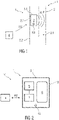
- figure 2 1 schematically shows an embodiment of a measuring device 1 with at least one detection unit 3 for detecting particles P in a pipeline 2 of a fluid transport system FT. Furthermore shows figure 2 a device V for the transmission of data from the pipeline 2.
- the detection unit 3 comprises at least one camera unit 5 for detecting the particles P carried along in the medium M.
- the detection unit 3 comprises at least one filter unit 6.
- the filter unit 6 is provided to provide the particles P to be detected with a fluorescent marking. As soon as the medium M comes into contact with the filter unit 6, the particles P can be provided with the fluorescent marking.
- the filter unit 6 comprises a plurality of particles, in particular antibodies, which trigger a chemical reaction on a particle surface when they come into contact with particles P, which are particularly harmful to health, as a result of which the particles P fluoresce.
- the camera unit 5 is designed to be able to capture the fluorescent particles P.
- the camera unit 5 is configured to capture the fluorescent particles P in the so-called VIS range. Recorded data, such as image data, are then evaluated.
- the camera unit 5 is coupled to an evaluation unit 7 .
- the evaluation unit 7 is designed in the form of evaluation electronics, comprising at least software and algorithms, for evaluating the recorded data.
- the occurrence of the particles P and/or a particle concentration and/or a particle density can be detected using pattern recognition and/or a pattern comparison and/or an algorithm.
- the particles P are quantified by determining a surface (determined by integration) that is covered by particles P in the camera image. Subsequently, recorded data on the particle-covered surface are set in relation to the entire recorded surface in the pipe interior 2.1.
- the evaluation unit 7 works, for example, with what is known as pattern matching or a learning algorithm in order to classify and quantify the particles P. A learning process can be carried out in order to configure the algorithm with regard to a classification.
- the device V includes the measuring device 1 and a data processing unit 4.
- the measuring device 1 and the data processing unit 4 can be connected to one another via a communication link KV, in particular a wireless communication link KV.
Landscapes
- Chemical & Material Sciences (AREA)
- Health & Medical Sciences (AREA)
- Life Sciences & Earth Sciences (AREA)
- General Physics & Mathematics (AREA)
- Physics & Mathematics (AREA)
- Analytical Chemistry (AREA)
- Biochemistry (AREA)
- General Health & Medical Sciences (AREA)
- Immunology (AREA)
- Pathology (AREA)
- Dispersion Chemistry (AREA)
- Engineering & Computer Science (AREA)
- Food Science & Technology (AREA)
- Medicinal Chemistry (AREA)
- Signal Processing (AREA)
- Measuring Or Testing Involving Enzymes Or Micro-Organisms (AREA)
Description
- Die Erfindung betrifft eine Rohrleitung mit einer Messvorrichtung, insbesondere eine Sensoreinheit, zur Erfassung von Partikeln in einer Rohrleitung. Des Weiteren betrifft die Erfindung eine Vorrichtung zur Übermittlung von Daten aus einer Rohrleitung mit einer solchen Messvorrichtung.
- Fluidtransportsysteme, insbesondere Rohrleitungssysteme, wie zum Beispiel Wasserversorgungsanlagen und/oder Trinkwasseranlagen versorgen täglich eine Vielzahl von Wohneinheiten mit Trinkwasser. In Abhängigkeit von unterschiedlichen, gesundheitsschädlichen Partikeln im Trinkwasser können Personen erkranken.
- Aus dem Stand der Technik sind Messvorrichtungen bekannt, die zur Prüfung der Wasser- und/oder Trinkwasserqualität eine Probeentnahme benötigen. Für die Probeentnahme muss eine Wasserzufuhr verriegelt und die Rohrleitung an einer bestimmten Stelle zur Probeentnahme geöffnet werden. Andere Messvorrichtungen werden in verifizierten Laboren (nach Trinkwasserschutzverordnung) bereitgestellt, die zur Prüfung der Wasser- und/oder Trinkwasserqualität ebenfalls eine Probeentnahme benötigen. Die Probe wird an das Labor übermittelt, welche mittels geeigneter Messvorrichtungen die Wasser- und/oder Trinkwasserqualität prüfen.
- Beispielsweise sind Vorrichtungen und Verfahren zur Ermittlung von Partikeln in einem Fluid aus der
WO 2010/051842 A1 , derWO 2018/001627 A1 , derUS 2017/219550 A1 und derUS 2017/242234 A1 bekannt. - Der Erfindung liegt die Aufgabe zu Grunde, eine gegenüber dem Stand der Technik verbesserte Messvorrichtung zur Erfassung von Partikeln in einer Rohrleitung anzugeben.
- Hinsichtlich der Rohrleitung mit einer Messvorrichtung wird die Aufgabe erfindungsgemäß durch die im Anspruch 1 angegebenen Merkmale gelöst. Hinsichtlich der Vorrichtung zur Übermittlung von Daten aus einer Rohrleitung wird die Aufgabe durch die im Anspruch 12 angegebenen Merkmale gelöst.
- Vorteilhafte Ausgestaltungen der Erfindung sind Gegenstand der Unteransprüche.
- Die Messvorrichtung zur Erfassung von Partikeln in einer Rohrleitung umfasst zumindest eine Erfassungseinheit, die in einem Rohrinnenraum der Rohrleitung angeordnet ist, wobei der Rohrinnenraum ein Medium, wie beispielsweise Wasser und/oder Trinkwasser, aufweist und/oder mit einem Medium durchströmbar ist, wobei die Erfassungseinheit ausgebildet ist, zumindest ein Auftreten unterschiedlicher Partikel im Medium zu erfassen. Beispielsweise ist der Rohrinnenraum mit einem Medium, wie beispielsweise Wasser und/oder Trinkwasser, befüllt. Des Weiteren kann der Rohrinnenraum mit einem Medium, wie Wasser und/oder Trinkwasser, zur Weiterleitung des Mediums durchströmt werden.
- Beispielsweise ist die Messvorrichtung teilweise oder vollständig in der Rohrleitung integriert, insbesondere im Rohrinnenraum fixiert. Die Rohrleitung ist beispielsweise Teil eines Fluidtransportsystems, wie beispielsweise eines Wasserversorgungssystems. Das Wasserversorgungssystem, wie beispielsweise eine Wasserversorgungsanlage, stellt Wasser und/oder Trinkwasser für zumindest eine Wohneinheit, beispielsweise Wohnung oder Haus, bereit. Die Rohrleitung kann selbst ein Fluidtransportsystem sein. Die Erfassungseinheit ist beispielsweise ein Messgerät.
- Die Messvorrichtung ist ausgebildet, um das Medium, wie beispielsweise Wasser und/oder Trinkwasser, kontinuierlich und/oder in vorgebbaren Zeitabständen auf gesundheitsschädliche Partikel zu prüfen. Insbesondere können Partikel, insbesondere schädliche Fremdstoffe, im Medium frühzeitig erkannt werden.
- Beispielsweise werden nicht sichtbare, insbesondere für Menschen, gesundheitsschädliche Partikel im Medium mitgeführt, die die Hygiene des Mediums beeinträchtigen. Die Erfassungseinheit umfasst beispielsweise eine Steuereinheit, mittels welche die Erfassungseinheit programmierbar ist. Beispielsweise ist die Erfassungseinheit von außen ansteuerbar, beispielsweise einstellbar, konfigurierbar. Die Erfassungseinheit kann auch bereits im Werk eingestellt bzw. konfiguriert werden. Die Erfassungseinheit kann auch nach Installation in der Rohrleitung eingestellt bzw. konfiguriert werden. Die Erfassungseinheit muss zur Einstellung derselben nicht aus der Rohrleitung demontiert werden. Die Erfassungseinheit weist beispielsweise eine Anzahl von Schnittstellen, wie Kommunikationsschnittstellen, insbesondere drahtlose Kommunikationsschnittstellen auf. Über eine oder mehrere Schnittstellen kann die Erfassungseinheit mit einem zentralen Server verbunden werden. Über eine oder mehrere Schnittstellen kann die Erfassungseinheit mit einem mobilen Gerät eines Nutzers verbunden werden.
- Vorteile der Erfindung bestehen darin, dass der Rohrinnenraum zu jeder Zeit nach gesundheitsschädlichen oder anderen, zu prüfenden Partikeln prüfbar ist, wobei aufwändige, herkömmliche Probeentnahmen entfallen. Insbesondere sind ein Zeitaufwand und ein Kostenaufwand zur Prüfung des Mediums verringert. Zudem ist beispielsweise eine Tendenz zur Zunahme einer Partikelkonzentration gesundheitsschädlicher Partikel frühzeitig erkennbar. Die Erfassungseinheit ist beispielsweise für Wartungsarbeiten lösbar im Rohrinnenraum fixiert. Insbesondere erfolgt eine Datenübertragung drahtlos. Zum Beispiel ist die Erfassungseinheit ausgebildet, mit stationären oder mobilen Datenverarbeitungseinheiten und/oder Datensammlern zu kommunizieren. Beispielsweise weist die Erfassungseinheit eine Anzahl von Schnittstellen auf. Mittels der Anordnung der Erfassungseinheit direkt im Rohrinnenraum ist dieser kontinuierlich überwachbar. Die Erfassungseinheit ist beispielsweise ausgebildet, in vorgebbaren Zeitabständen Daten zum Zustand des Mediums zu erfassen. Das in der Rohrleitung eines Wasserversorgungssystems transportierte Medium kann insbesondere gegenüber dem Stand der Technik in unkomplizierter Weise auf Hygiene geprüft werden.
- Die Messvorrichtung ist beispielsweise als ein Montagemodul an einer geeigneten Mediumdurchflussstelle oder Mediumstehstelle innerhalb der Rohrleitung, wie einer Wasserleitung, angeordnet und montiert, beispielsweise verschraubt. Die Erfassungseinheit ist beispielsweise eine Sensoreinheit. Da die Erfassungseinheit innerhalb der Rohrleitung angeordnet und montiert ist, ist keine zusätzliche und zeitaufwendige Probeentnahme benötigt. Die Erfassungseinheit prüft das Medium beispielsweise während es durch die Rohrleitung durchfließt oder in der Rohrleitung steht, ob gefährliche und/oder gesundheitsschädliche biologische Partikel, wie Legionellen im Medium, insbesondere Wasser vorhanden sind.
- In einer Weiterbildung ist die Erfassungseinheit ausgebildet, biologische Partikel im Wasser und/oder Trinkwasser zu klassifizieren und zu quantifizieren. Zum Beispiel werden unter biologischen Partikeln Pilze und Bakterien, wie Kolibakterien (Escherichia coli, kurz auch E.coli), Legionellen oder andere gesundheitsschädliche Partikel und/oder Schädlinge verstanden. Darüber hinaus ist es möglich, das Medium auf andere Schadstoffe, wie Korrosionsprodukte, zu überprüfen. Insbesondere sind im Medium mitgeführte Partikel mittels der Erfassungseinheit erfassbar. Beispielsweise ist die Erfassungseinheit ausgebildet, Partikelarten zu klassifizieren. Des Weiteren ist die Erfassungseinheit ausgebildet, einen Partikelanteil (Volumenanteil), eine Partikelkonzentration (Volumenkonzentration), ein Volumenverhältnis beispielsweise in Volumenprozent in Bezug auf ein Volumen des Mediums und/oder eine Partikeldichte und/oder einen Massenanteil zu ermitteln.
- Zum Beispiel ist die Erfassungseinheit konfiguriert, zur Quantifizierung der Partikel die so genannte koloniebildende Einheit (kurz: KBE) zu verwenden. Grenz- und Richtwerte, beispielsweise für mikrobiologische Parameter, sind in der Trinkwasserverordnung (TrinkwV) aufgeführt. Weiterhin ist die Erfassungseinheit konfiguriert, eine statistische Verteilung der Partikel im Medium zu ermitteln. Beispielsweise umfasst die Erfassungseinheit eine Auswerteeinheit. Die Auswerteeinheit ist in Form einer Auswerteelektronik, umfassend eine Software und Algorithmen, in die Erfassungseinheit eingebettet. Dadurch können herkömmliche Schritte, wie zum Beispiel Abriegeln der Rohrleitung und/oder einer Mediumzufuhr, Entnahme des Mediums, Bestücken eines Testgeräts, entfallen. Darüber hinaus ist die in der Rohrleitung angeordnete und beispielsweise integrierte Erfassungseinheit ausgebildet, bei Ansteuerung zur Durchführung einer Prüfung das Medium unmittelbar zu prüfen. Daten über das Medium können also in Echtzeit permanent erfasst und übertragen werden. Dies führt zu einem schnellen Ergebnis mit geringem Zeitaufwand gegenüber herkömmlichen Maßnahmen. Zudem ist eine "Online- Überwachung und Datenübertragung" möglich.
- Beispielsweise ist die Erfassungseinheit in einem Netzwerk, wie einem Kommunikationsnetzwerk eingebunden und kann über zumindest eine Kommunikationsschnittstelle mit externen und/oder zentralen Servern und Geräten kommunizieren. Zum Beispiel ist es möglich, rein erfasste und noch nicht ausgewertete Daten und/oder bereits durch die Erfassungseinheit, insbesondere die in der Erfassungseinheit integrierte Auswerteeinheit ermittelte, d.h. ausgewertete Daten zu übermitteln. Beispielsweise werden die Daten an eine Datenverarbeitungseinheit, wie beispielsweise ein mobiles Endgerät eines Nutzers, und/oder an einen zentralen Server, einer Cloud und/oder an ein Labor übermittelt. Zum Beispiel sendet die Erfassungseinheit die Daten, wenn die Erfassungseinheit über eine drahtlose Kommunikationsschnittstelle eine vom zentralen Server und/oder vom externen Gerät ausgesendete Anforderung empfängt.
- In einer weiteren Ausführungsform sind die Daten mit einem Zeitstempel für weitere zeitabhängige Analysen und statistische Verarbeitung der Daten versehen.
- Gemäß einer weiteren Ausführungsform ist die Erfassungseinheit ausgebildet, von einem flüssigen Medium durchströmt zu werden. Alternativ oder zusätzlich ist die Erfassungseinheit ausgebildet, im Medium zu stehen. Beispielsweise ist die Erfassungseinheit im Wesentlichen kreisförmig ausgebildet. Zum Beispiel korrespondiert eine Abmessung, wie ein Durchmesser, der Erfassungseinheit mit einem Querschnitt der Rohrleitung. Am Außenumfang der Erfassungseinheit sind beispielsweise lösbare Fixierungselemente angeordnet. Im Rohrinnenraum sind mit den lösbaren Fixierungselementen der Erfassungseinheit korrespondierende Fixierungspunkte ausgebildet. Zum Beispiel ist die Erfassungseinheit ringförmig ausgebildet. Die Erfassungseinheit umfasst eine oder mehrere Öffnung/en, durch welche das Medium durchströmen kann.
- Die Erfassungseinheit ist beispielsweise gegenüber dem Querschnitt der Rohrleitung kleiner ausgebildet. Beispielsweise ist die Erfassungseinheit an einem Innenwandungsabschnitt der Rohrleitung befestigt. Zum Beispiel ist die Erfassungseinheit am Innenwandungsabschnitt lösbar fixiert.
- In einer Weiterbildung ist die Erfassungseinheit Stoff-, kraft- und/oder formschlüssig mit dem Rohrinnenraum verbunden.
- Eine weitere mögliche Ausgestaltung sieht vor, dass die Erfassungseinheit in einem Steigleitungsabschnitt oder einem Totleitungsabschnitt der Rohrleitung angeordnet ist.
- Die Erfassungeinheit umfasst eine Filtereinheit, die dazu ausgebildet ist, die zu erfassenden Partikel mit einer Fluoreszenzmarkierung zu versehen.
- In einer weiteren Ausgestaltung ist die Erfassungseinheit ausgebildet, fluoreszierende Partikel zu erfassen.
- Beispielsweise umfasst die Erfassungseinheit eine Mehrzahl von Teilchen, beispielsweise geeigneten Antikörpern, die mit unterschiedlichen Partikeln reagieren. Insbesondere sind die Partikel durch die Teilchen anregbar, sodass die Partikel fluoreszieren. Eine chemische Reaktion zwischen Partikel und Antikörper bewirkt also eine von der Erfassungseinheit erfassbare Fluoreszenz. Beispielsweise ist eine Biofluoreszenz mittels der Erfassungseinheit erfassbar.
- Gemäß einer Ausführungsform umfasst die Erfassungseinheit zumindest eine Kameraeinheit. Die Kameraeinheit ist ausgebildet, fluoreszierende Partikel zu erfassen. Beispielsweise ist die Kameraeinheit konfiguriert, die fluoreszierenden Partikel im sogenannten VIS-Bereich zu erfassen.
- Die Erfassungseinheit umfasst zumindest eine Filtereinheit, die ausgebildet ist, zu erfassende Partikel mit einer Fluoreszenzmarkierung zu versehen. Beispielsweise sind in der Filtereinheit spezielle Teilchen, wie Antikörper, angeordnet, die die insbesondere gesundheitsschädlichen Partikel zum Fluoreszieren bringen. Insbesondere ist die Filtereinheit ausgebildet, vom Medium durchströmt zu werden und die im Medium mitgeführten gesundheitsschädlichen Partikel mit einer Fluoreszenzmarkierung zu versehen.
- In einer möglichen weiteren Ausbildung sind die Kameraeinheit und die Filtereinheit in Form eines Messumformers ausgebildet. Beispielsweise umfasst die Erfassungseinheit einen Messumformer sowie einer Auswerteelektronik mit Software.
- In einer möglichen Ausgestaltung ist die Erfassungseinheit zumindest teilweise lösbar im Rohrinnenraum fixiert. Dadurch können Wartungsarbeiten, Reparaturarbeiten sowie ein Austausch von in der Erfassungseinheit integrierten Komponenten in einfacher Weise durchgeführt werden. Beispielsweise ist die Filtereinheit in einem Nebenpfad der Rohrleitung, insbesondere eines Medienflusses, angeordnet, wobei der Nebenpfad zum Zweck von Wartungsarbeiten, Auswechslung und/oder Reinigung der Filtereinheit vom Medium abgeriegelt werden kann. Des Weiteren ist beispielsweise die Kameraeinheit zum Zweck von Wartungsarbeiten und/oder Reinigung jederzeit entfernbar.
- Eine weitere mögliche Ausgestaltung sieht vor, dass die Erfassungseinheit ausgebildet ist, anhand einer Mustererkennung und/oder eines Musterabgleichs und/oder eines Algorithmus das Auftreten von Partikeln und/oder eine Partikelkonzentration und/oder eine Partikeldichte zu ermitteln. Zum Beispiel umfasst die Kameraeinheit eine Kamerasoftware. Beispielsweise ist die Kameraeinheit mit einer Auswerteeinheit gekoppelt. Eine Quantifizierung der Partikel erfolgt durch Ermittlung einer (per Integration ermittelten) Oberfläche, die im Kamerabild von Partikeln bedeckt ist. Anschließend werden erfasste Daten zur partikelbedeckten Oberfläche in Verhältnis zur gesamten erfassten Oberfläche im Rohrinnenraum gesetzt. Insbesondere arbeitet die Kamerasoftware und/oder die Auswerteeinheit beispielsweise mit einem sogenannten Pattern-Matching oder einem lernenden und/oder analytischen Algorithmus, um die Partikel zu klassifizieren und zu quantifizieren. Dabei kann ein Einlernvorgang durchgeführt werden, um den Algorithmus bezüglich einer Klassifizierung zu konfigurieren. Alternativ oder zusätzlich wird ein analytischer Algorithmus eingesetzt, wobei beispielsweise dunkle und nicht dunkle Flächen im Medium ermittelt werden.
- In einer Weiterbildung ist die Erfassungseinheit ausgebildet, ermittelte Daten an eine Datenverarbeitungseinheit zu übertragen. Beispielsweise umfasst die Erfassungseinheit Schnittstellen zur drahtlosen Übermittlung der erfassten Daten. In einer weiteren Ausgestaltung ist die Erfassungseinheit in ein Netzwerk eingebunden und liefert permanent Daten über eine mögliche Wasser- und/oder Trinkwasserverschmutzung, die dann beispielsweise von einem Kunden per Applikationssoftware oder mit einer anderen Auswerteplattform abrufbar ist. Der Kunde ist beispielsweise Betreiber des Wasserversorgungssystems. Bei Erfassung von erhöhter Wasser- und/oder Trinkwasserverschmutzung durch gesundheitsschädliche Partikel kann die Erfassungseinheit eine Information ausgeben, dass eine Spülung oder eine anderweitige Reinigung des Mediums und/oder der Rohrleitung veranlasst werden soll. Die ermittelten Daten können zudem an ein akkreditiertes Labor übermittelt werden, um beispielsweise eine Korrelation zwischen Laborergebnis und den mittels der Erfassungseinheit ermittelten Daten durchzuführen.
- Des Weiteren betrifft die Erfindung eine Vorrichtung zur Übermittlung von Daten aus einer Rohrleitung, umfassend zumindest eine Messvorrichtung gemäß der vorhergehenden Beschreibung, und zumindest eine mit der Messvorrichtung gekoppelte und/oder koppelbare Datenverarbeitungseinheit, wie einem zentralen Server oder eines mobilen Endgeräts, wobei die Messvorrichtung erfasste Daten und/oder ermittelte Daten an die Datenverarbeitungseinheit drahtlos übermittelt. Die Messvorrichtung übermittelt erfasste Daten und/oder ermittelte Daten kontinuierlich und/oder in vorgebbaren Zeitabständen an die Datenverarbeitungseinheit.
- Des Weiteren betrifft die Erfindung eine Rohrleitung mit einem Rohrinnenraum und einem in dem Rohrinnenraum befindlichen Medium, wobei im Rohrinnenraum zumindest eine Messvorrichtung nach obiger Beschreibung angeordnet ist.
- Insbesondere ist eine weitestgehend schnelle, effektive und unkomplizierte Überwachung des Rohrinnenraums möglich.
- Ausführungsbeispiele der Erfindung werden im Folgenden anhand von Zeichnungen näher erläutert.
- Darin zeigen:
- Figur 1
- schematisch eine Ausführungsform einer Messvorrichtung mit zumindest einer Erfassungseinheit zur Erfassung von Partikeln in einer Rohrleitung, wobei die Erfassungseinheit in einem Rohrinnenraum der Rohrleitung angeordnet ist, und
- Figur 2
- schematisch eine Ausführungsform einer Messvorrichtung mit zumindest einer Erfassungseinheit, umfassend zumindest eine Filtereinheit und eine Kameraeinheit.
- Einander entsprechende Teile sind in allen Figuren mit den gleichen Bezugszeichen versehen.
-
Figur 1 zeigt schematisch eine Ausführungsform einer Messvorrichtung 1 zur Erfassung von Partikeln P in einer Rohrleitung 2, beispielsweise eines Rohrleitungssystems, insbesondere einer Trinkwasseranlage. Die Rohrleitung 2 ist beispielsweise Teil eines Fluidtransportsystems FT, insbesondere eines Wassertransportsystems. - Die Messvorrichtung 1 umfasst zumindest eine Erfassungseinheit 3, die in einem Rohrinnenraum 2.1 angeordnet ist. Der gezeigte Rohrleitungsabschnitt ist beispielsweise ein Steigleitungsabschnitt oder ein Totleitungsabschnitt der Rohrleitung 2. Die Erfassungseinheit 3 ist beispielsweise als elektronisches Messgerät ausgebildet. Die Erfassungseinheit 3 ist beispielsweise ein in der Rohrleitung 2 stationäres Messgerät.
- Der Rohrinnenraum 2.1 weist ein Medium M auf. Das Medium M ist beispielsweise Wasser und/oder Trinkwasser. Beispielsweise durchströmt das Medium M den Rohrinnenraum 2.1. Zum Beispiel steht das Medium M in der Rohrleitung 2.
- Die Erfassungseinheit 3 ist ausgebildet, zumindest ein Auftreten unterschiedlicher Partikel P, insbesondere gesundheitsschädlicher Partikel, im Medium M zu erfassen.
- Die Messvorrichtung 1 ist als ein in der Rohrleitung 2 stationäres Montagemodul ausgebildet und umfasst ein Gehäuse 3.1, welches die Erfassungseinheit 3 umgibt und kapselt. Das Gehäuse 3.1 kann ein- oder mehrteilig ausgebildet sein. Das Gehäuse 3.1 ist mediumdurchlässig ausgebildet.
- Die Erfassungseinheit 3 ist ausgebildet, biologische Partikel P im Wasser und/oder Trinkwasser zu klassifizieren und zu quantifizieren. Zum Beispiel werden unter biologischen Partikel P Pilze und Bakterien, wie Kolibakterien (Escherichia coli, kurz auch E.coli), Legionellen oder andere gesundheitsschädliche Partikel und/oder Schädlinge verstanden. Darüber hinaus ist es möglich, das Medium M auf andere Schadstoffe, wie Korrosionsprodukte, zu überprüfen. Insbesondere sind im Medium M mitgeführte Partikel P mittels der Erfassungseinheit 3 erfassbar. Beispielsweise ist die Erfassungseinheit 3 ausgebildet, Partikelarten zu klassifizieren. Des Weiteren ist die Erfassungseinheit 3 ausgebildet, einen Partikelanteil (Volumenanteil), eine Partikelkonzentration (Volumenkonzentration), ein Volumenverhältnis beispielsweise in Volumenprozent (Vol-%) in Bezug auf ein Volumen des Mediums M und/oder eine Partikeldichte und/oder einen Massenanteil (Masse-%) zu ermitteln.
- Die Erfassungseinheit 3 ist beispielsweise ausgebildet, von einem flüssigen Medium M durchströmt zu werden. Alternativ oder zusätzlich ist die Erfassungseinheit 3 ausgebildet, im Medium M zu stehen.
- Die Erfassungseinheit 3 ist beispielsweise an einem Innenwandungsabschnitt 2.2 der Rohrleitung 2 befestigt oder lösbar befestigt. Insbesondere ist das Gehäuse 3.1 am Innenwandungsabschnitt 2.2 fixiert. Die Erfassungseinheit 3 ist beispielsweise gegenüber dem Querschnitt der Rohrleitung 2 kleiner ausgebildet. Alternativ korrespondiert eine Abmessung, wie ein Durchmesser, der Erfassungseinheit 3 mit dem Querschnitt der Rohrleitung 2. Das Gehäuse 3.1 kann beispielsweise gegenüber dem Querschnitt der Rohrleitung 2 kleiner ausgebildet sein oder eine Abmessung aufweisen, die der Abmessung der Rohrleitung 2, insbesondere im Querschnitt, entspricht. Beispielsweise umfasst das Gehäuse 3.1 Fixierungselemente 3.2. Die Fixierungselemente 3.2 sind beispielsweise Schraubelemente, Nietelemente, Clips- oder andere Rastelemente. In einer weiteren Ausführungsform sind die Fixierungselemente 3.2 stoffschlüssige Verbindungselemente. Beispielsweise sind die Fixierungselemente 3.2 Schweiß- oder Lötelemente.
- Des Weiteren umfasst die Erfassungseinheit 3 eine Filtereinheit 6, die ausgebildet ist, die zu erfassenden Partikel P mit einer Fluoreszenzmarkierung zu versehen. Dabei ist die Erfassungseinheit 3 ausgebildet, fluoreszierende Partikel P zu erfassen. Beispielsweise umfasst die Erfassungseinheit 3 eine Mehrzahl von Teilchen, beispielsweise geeigneten Antikörpern, die mit unterschiedlichen Partikeln P reagieren können. Insbesondere sind die Partikel P durch die Teilchen anregbar, sodass die Partikel P fluoreszieren. Eine chemische Reaktion zwischen Partikel P und Teilchen bewirkt also eine von der Erfassungseinheit 3 erfassbare Fluoreszenz. Beispielsweise ist eine Biofluoreszenz mittels der Erfassungseinheit 3 erfassbar.
- Zur Aufnahme der Teilchen umfasst die Erfassungseinheit 3 beispielsweise eine hier nicht näher dargestellte Aufnahmevorrichtung, durch welche das Medium M durchströmen kann.
- Zur Partikelerfassung umfasst die Erfassungseinheit 3 beispielsweise einen Sensor.
- Beispielsweise ist die Erfassungseinheit 3 ausgebildet ist, anhand einer Mustererkennung und/oder eines Musterabgleichs und/oder eines Algorithmus das Auftreten von Partikeln P und/oder eine Partikelkonzentration und/oder eine Partikeldichte zu ermitteln. Hierfür umfasst die Erfassungseinheit 3 beispielsweise eine Auswerteeinheit 7. Die Auswerteeinheit 7 ist in Form einer Auswerteelektronik, umfassend eine Software und Algorithmen, in die Erfassungseinheit 3 eingebettet.
- Des Weiteren erfolgt eine Übertragung erfasster Daten drahtlos. Zum Beispiel ist die Erfassungseinheit 3 ausgebildet, mit stationären oder mobilen Datenverarbeitungseinheiten 4 zu kommunizieren. Beispielsweise weist die Erfassungseinheit 3 eine Anzahl von Schnittstellen, insbesondere Kommunikationsschnittstellen KS, auf. Über die Datenverarbeitungseinheit 4 können mittels der Erfassungseinheit 3 ermittelte und/oder erfasste Daten an Kunden übermittelt werden. Zum Beispiel ist die Erfassungseinheit 3 eingerichtet, erfasste Daten selbst auszuwerten und diese als ermittelte Daten zu übermitteln. Alternativ zusätzlich übermittelt die Erfassungseinheit 3 rein erfasste, nicht ausgewertete Daten.
- In einer Weiterbildung ist die Erfassungseinheit 3 in ein Netzwerk eingebunden und liefert permanent Daten über eine mögliche Wasser- und/oder Trinkwasserverschmutzung, die dann beispielsweise von einem Kunden per Applikationssoftware oder mit einer anderen Auswerteplattform abrufbar ist. Der Kunde ist beispielsweise Betreiber des Wasserversorgungssystems. Bei Erfassung von erhöhter Wasser- und/oder Trinkwasserverschmutzung durch gesundheitsschädliche Partikeln P kann die Erfassungseinheit 3 eine Information ausgeben, dass eine Spülung oder eine anderweitige Reinigung des Mediums M und/oder der Rohrleitung 2 veranlasst werden soll. Die ermittelten und/oder erfassten Daten können zudem an ein akkreditiertes Labor übermittelt werden, um beispielsweise eine Korrelation zwischen Laborergebnis und den mittels der Erfassungseinheit 3 ermittelten Daten durchzuführen. Die Datenverarbeitungseinheit 4 ist beispielsweise ein mobiles Endgerät eines Nutzers oder ein zentraler Server. Die Datenverarbeitungseinheit 4 ist beispielsweise eine Recheneinheit. Die Datenverarbeitungseinheit 4 ist beispielsweise ein so genannter Cloud-Speicherplatz. Zum Beispiel ist die Datenverarbeitungseinheit 4 eingerichtet, mit der Erfassungseinheit 3 beispielsweise über ein drahtloses Netzwerk, wie ein globales Netzwerk, Daten der Erfassungseinheit 3 zu empfangen.
- Die Messvorrichtung 1 ist eingerichtet, direkt Daten zu erfassen und diese über die Kommunikationsschnittstelle KS zu übertragen. Zum Beispiel ist die Kommunikationsschnittstelle KS als Funkschnittstelle ausgebildet. Die Kommunikationsschnittstelle KS ist ausgebildet, die Erfassungseinheit 3 mit der Datenverarbeitungseinheit 4 zu verbinden. Zum Beispiel werden die Daten an die Datenverarbeitungseinheit 4 übertragen, damit ein Nutzer und/oder ein Kunde zeitnah aktuelle Informationen über das Medium M erhält. Des Weiteren werden die Daten an die Datenverarbeitungseinheit 4 übertragen, damit die Daten beispielsweise von einem Labor erfasst und überprüft werden können.
- Die Erfassungseinheit 3 kann eine Steuereinheit umfassen. Alternativ kann eine separate Steuereinheit (nicht näher dargestellt) in der Messvorrichtung 1 vorgesehen sein. Die Erfassungseinheit 3 und die Steuereinheit sind datentechnisch miteinander gekoppelt. Darüber hinaus können/kann die Messvorrichtung 1 und/oder die Erfassungseinheit 3 einen nicht näher dargestellten Speicher zur Speicherung erfasster und/oder ermittelter Daten umfassen. Über die Steuereinheit ist die Erfassungseinheit 3 ansteuerbar. Zudem kann die Erfassungseinheit 3 über die Steuereinheit konfiguriert werden.
- Zum Beispiel ist eine Kommunikationsverbindung KV zwischen der Erfassungseinheit 3 und der Datenverarbeitungseinheit 4 zur Datenübertragung herstellbar oder hergestellt. Die Kommunikationsverbindung KV erfolgt über eine oder mehrere Kommunikationsschnittstellen KS. Beispielsweise umgibt und kapselt das Gehäuse 3.1 die Erfassungseinheit 3 und die zumindest eine Kommunikationsschnittstelle KS.
- Des Weiteren betrifft die Erfindung eine Rohrleitung 2 mit einem Rohrinnenraum 2.1 und einem in dem Rohrinnenraum 2.1 befindlichen Medium M, wobei im Rohrinnenraum 2.1 zumindest eine Messvorrichtung 1 nach obiger Beschreibung angeordnet ist.
- Mittels der Anordnung der Erfassungseinheit 3 direkt im Rohrinnenraum 2.1 ist dieser kontinuierlich/permanent und/oder in vorgebbaren Zeitabständen und/oder bei einer Befehlseingabe vergleichsweise unkompliziert überwachbar. Die Erfassungseinheit 3 ist beispielsweise ausgebildet, in vorgebbaren Zeitabständen Daten zum Zustand des Mediums M zu erfassen. Das in der Rohrleitung 2 transportierte und/oder befindliche Medium M kann insbesondere gegenüber dem Stand der Technik in unkomplizierter Weise auf dessen Hygiene geprüft werden.
-
Figur 2 zeigt schematisch eine Ausführungsform einer Messvorrichtung 1 mit zumindest einer Erfassungseinheit 3 zur Erfassung von Partikeln P in einer Rohrleitung 2 eines Fluidtransportsystems FT. Des Weiteren zeigtFigur 2 eine Vorrichtung V zur Übermittlung von Daten aus der Rohrleitung 2. - Die Erfassungseinheit 3 umfasst zumindest eine Kameraeinheit 5 zur Erfassung der im Medium M mitgeführten Partikel P.
- Des Weiteren umfasst die Erfassungseinheit 3 zumindest eine Filtereinheit 6. Die Filtereinheit 6 ist vorgesehen, die zu erfassenden Partikel P mit einer Fluoreszenzmarkierung zu versehen. Sobald das Medium M mit der Filtereinheit 6 in Berührung kommt, können die Partikel P mit der Fluoreszenzmarkierung versehen werden. Beispielsweise umfasst die Filtereinheit 6 eine Mehrzahl von Teilchen, insbesondere Antikörpern, die bei Berührung mit insbesondere gesundheitsschädlichen Partikeln P eine chemische Reaktion an einer Partikeloberfläche auslösen, wodurch die Partikel P fluoreszieren.
- Die Kameraeinheit 5 ist ausgebildet, die fluoreszierenden Partikel P erfassen zu können. Insbesondere ist die Kameraeinheit 5 konfiguriert, die fluoreszierenden Partikel P im sogenannten VIS-Bereich zu erfassen. Erfasste Daten, wie Bilddaten, werden anschließend ausgewertet. Zum Beispiel ist die Kameraeinheit 5 mit einer Auswerteeinheit 7 gekoppelt.
- Die Auswerteeinheit 7 ist in Form einer Auswerteelektronik, umfassend zumindest eine Software und Algorithmen, zur Auswertung der erfassten Daten ausgebildet. Anhand einer Mustererkennung und/oder eines Musterabgleichs und/oder eines Algorithmus sind/ist das Auftreten der Partikel P und/oder eine Partikelkonzentration und/oder eine Partikeldichte erfassbar. Eine Quantifizierung der Partikel P erfolgt durch Ermittlung einer (per Integration ermittelten) Oberfläche, die im Kamerabild von Partikeln P bedeckt ist. Anschließend werden erfasste Daten zur partikelbedeckten Oberfläche in Verhältnis zur gesamten erfassten Oberfläche im Rohrinnenraum 2.1 gesetzt. Insbesondere arbeitet die Auswerteeinheit 7 beispielsweise mit einem sogenannten Pattern-Matching oder einem lernenden Algorithmus, um die Partikel P zu klassifizieren und zu quantifizieren. Dabei kann ein Einlernvorgang durchgeführt werden, um den Algorithmus bezüglich einer Klassifizierung zu konfigurieren.
- Die Vorrichtung V umfasst die Messvorrichtung 1 und eine Datenverarbeitungseinheit 4. Die Messvorrichtung 1 und die Datenverarbeitungseinheit 4 sind über eine Kommunikationsverbindung KV, insbesondere einer drahtlosen Kommunikationsverbindung KV, miteinander verbindbar oder verbunden.
-
- 1
- Messvorrichtung
- 2
- Rohrleitung
- 2.1
- Rohrinnenraum
- 2.2
- Innenwandungsabschnitt
- 3
- Erfassungseinheit
- 3.1
- Gehäuse
- 3.2
- Fixierungselement
- 4
- Datenverarbeitungseinheit
- 5
- Kameraeinheit
- 6
- Filtereinheit
- 7
- Auswerteeinheit
- FT
- Fluidtransportsystem
- KS
- Kommunikationsschnittstelle
- KV
- Kommunikationsverbindung
- M
- Medium
- P
- Partikel
- V
- Vorrichtung
Claims (13)
- Rohrleitung (2) mit einer Messvorrichtung (1) zur Erfassung von Partikeln (P), wobei die Messvorrichtung (1)- zumindest eine Erfassungseinheit (3) umfasst, die in einem Rohrinnenraum (2.1) der Rohrleitung (2) angeordnet ist, wobei der Rohrinnenraum (2.1) ein Medium (M) aufweist und/oder mit einem Medium (M) durchströmbar ist, und- wobei die Erfassungseinheit (3) ausgebildet ist, zumindest ein Auftreten unterschiedlicher Partikel (P) im Medium (M) zu erfassen, und- wobei die Erfassungseinheit (3) zumindest eine Filtereinheit (6) umfasst, die ausgebildet ist, zu erfassende Partikel (P) mit einer Fluoreszenzmarkierung zu versehen.
- Rohrleitung (2) nach Anspruch 1, wobei die Erfassungseinheit (3) ausgebildet ist, biologische Partikel (P) im Wasser und/oder Trinkwasser zu klassifizieren und zu quantifizieren.
- Rohrleitung (2) nach Anspruch 1 oder 2, wobei die Erfassungseinheit (3) in einem Steigleitungsabschnitt oder einem Totleitungsabschnitt der Rohrleitung (2) angeordnet ist.
- Rohrleitung (2) nach einem der vorhergehenden Ansprüche, wobei die Erfassungseinheit (3) ausgebildet ist, fluoreszierende Partikel (P) zu erfassen.
- Rohrleitung (2) nach einem der vorhergehenden Ansprüche, wobei die Erfassungseinheit (3) zumindest eine Kameraeinheit (5) umfasst.
- Rohrleitung (2) nach einem der vorhergehenden Ansprüche, wobei die Erfassungseinheit (3) zumindest teilweise lösbar im Rohrinnenraum (2.1) fixiert ist.
- Rohrleitung (2) nach einem der vorhergehenden Ansprüche, wobei die Erfassungseinheit (3) ausgebildet ist, anhand einer Mustererkennung und/oder eines Algorithmus das Auftreten von Partikeln (P) und/oder eine Partikelkonzentration und/oder eine Partikeldichte zu ermitteln.
- Rohrleitung (2) nach einem der vorhergehenden Ansprüche, wobei die Erfassungseinheit (3) ausgebildet ist, zumindest ermittelte Daten an eine Datenverarbeitungseinheit (4) zu übertragen.
- Rohrleitung (2) nach einem der vorhergehenden Ansprüche, wobei die Erfassungseinheit (3) zumindest eine Auswerteeinheit (7) umfasst.
- Rohrleitung (2) nach einem der vorhergehenden Ansprüche, wobei die Erfassungseinheit (3) eingestellt ist, das Medium (M) kontinuierlich und/oder in vorgebbaren Zeitabständen auf gesundheitsschädliche Partikel (P) zu prüfen.
- Rohrleitung (2) nach einem der vorhergehenden Ansprüche, wobei die Erfassungseinheit (3) zumindest eine Kommunikationsschnittstelle (KS) aufweist, mittels welcher die Erfassungseinheit (3) zumindest ermittelte Daten überträgt.
- Vorrichtung (V) zur Übermittlung von Daten aus einer Rohrleitung (2), umfassend- zumindest eine Messvorrichtung (1) nach einem der vorhergehenden Ansprüche 1 bis 11, und- zumindest eine mit der Messvorrichtung (1) gekoppelte und/oder koppelbare Datenverarbeitungseinheit (4), wobei die Messvorrichtung (1) erfasste Daten und/oder ermittelte Daten an die Datenverarbeitungseinheit (4) drahtlos übermittelt.
- Vorrichtung (V) nach Anspruch 12, wobei die Messvorrichtung (1) erfasste Daten und/oder ermittelte Daten kontinuierlich und/oder in vorgebbaren Zeitabständen an die Datenverarbeitungseinheit (4) übermittelt.
Applications Claiming Priority (1)
| Application Number | Priority Date | Filing Date | Title |
|---|---|---|---|
| DE102019204668.1A DE102019204668A1 (de) | 2019-04-02 | 2019-04-02 | Messvorrichtung zur Erfassung von Partikeln in einer Rohrleitung und Rohrleitung |
Publications (2)
| Publication Number | Publication Date |
|---|---|
| EP3719476A1 EP3719476A1 (de) | 2020-10-07 |
| EP3719476B1 true EP3719476B1 (de) | 2023-01-11 |
Family
ID=70165848
Family Applications (1)
| Application Number | Title | Priority Date | Filing Date |
|---|---|---|---|
| EP20167758.0A Active EP3719476B1 (de) | 2019-04-02 | 2020-04-02 | Rohrleitung mit einer messvorrichtung zur erfassung von partikeln und vorrichtung zur übermittlung von daten aus einer rohrleitung |
Country Status (2)
| Country | Link |
|---|---|
| EP (1) | EP3719476B1 (de) |
| DE (1) | DE102019204668A1 (de) |
Families Citing this family (2)
| Publication number | Priority date | Publication date | Assignee | Title |
|---|---|---|---|---|
| EP4012381B1 (de) * | 2020-12-09 | 2025-11-26 | Wilde, Axel | Vorrichtung und verfahren zum erfassen von partikeln in flüssigkeiten & gasen |
| CN113960970A (zh) * | 2021-10-27 | 2022-01-21 | 西安热工研究院有限公司 | 一种树脂输送过程智能监控系统及方法 |
Family Cites Families (10)
| Publication number | Priority date | Publication date | Assignee | Title |
|---|---|---|---|---|
| DE2632556C2 (de) * | 1976-07-20 | 1984-09-20 | Max Planck Gesellschaft zur Förderung der Wissenschaften e.V., 3400 Göttingen | Lichtzuführung für eine Vorrichtung zur optischen Messung von Stoffkonzentrationen |
| GB8408529D0 (en) * | 1984-04-03 | 1984-05-16 | Health Lab Service Board | Concentration of biological particles |
| EP0774112B1 (de) * | 1994-08-01 | 2002-07-03 | Abbott Laboratories | Pseudo-telezentrischer optischer aufbau für ein durchflusszytometrisches analysegerät für blutzellen |
| US5948684A (en) * | 1997-03-31 | 1999-09-07 | University Of Washington | Simultaneous analyte determination and reference balancing in reference T-sensor devices |
| AT407802B (de) * | 1998-02-26 | 2001-06-25 | Staudinger Gernot | Vorrichtung zur messung der zeitlichen entwicklung der transparenz eines in einer küvette sedimentierenden klärschlammes |
| WO2010051842A1 (en) * | 2008-11-05 | 2010-05-14 | Age Sa | Sensor arrangement and method for water quality monitoring |
| DE102012108989B3 (de) * | 2012-09-24 | 2014-01-23 | Eads Deutschland Gmbh | Detektionsvorrichtung sowie Verfahren zur automatischen Detektion von Partikeln |
| FR3024545B1 (fr) * | 2014-07-30 | 2018-05-18 | Suez Environnement | Systeme de mesure intelligent au point de livraison d'un fluide |
| CA3014099A1 (en) * | 2016-02-18 | 2017-08-24 | Optofluidics, Inc. | System and method for characterizing particulates in a fluid sample |
| FR3053359B1 (fr) * | 2016-06-30 | 2021-01-08 | Suez Groupe | Procede de controle de la concentration de bacteries dans un reseau de distribution d'eau |
-
2019
- 2019-04-02 DE DE102019204668.1A patent/DE102019204668A1/de not_active Ceased
-
2020
- 2020-04-02 EP EP20167758.0A patent/EP3719476B1/de active Active
Also Published As
| Publication number | Publication date |
|---|---|
| DE102019204668A1 (de) | 2020-10-08 |
| EP3719476A1 (de) | 2020-10-07 |
Similar Documents
| Publication | Publication Date | Title |
|---|---|---|
| DE102012108989B3 (de) | Detektionsvorrichtung sowie Verfahren zur automatischen Detektion von Partikeln | |
| DE102009029305A1 (de) | Analysegerät zur automatisierten Bestimmung einer Messgröße einer Flüssigkeitsprobe | |
| EP3719476B1 (de) | Rohrleitung mit einer messvorrichtung zur erfassung von partikeln und vorrichtung zur übermittlung von daten aus einer rohrleitung | |
| WO2016192966A1 (de) | Verfahren zur diagnose eines membranventils, sowie diagnosesystem für ein membranventil | |
| DE102017126612A1 (de) | Messeinrichtung zur Analyse eines Messmediums | |
| DE102012102296A1 (de) | Messanordnung umfassend mindestens ein erstes Analysegerät zur automatisierten Bestimmung einer Messgröße einer Flüssigkeit und eine Probenvorbereitungseinrichtung | |
| EP4118039B1 (de) | System zur analyse von wasser | |
| EP3130926B1 (de) | Verfahren zur bereitstellung eines reaktionsansatzes und automatisches analysegerät | |
| EP1743227B1 (de) | Elektrisches feldgerät für die prozessautomatisierung | |
| DE102008016763A1 (de) | Vorrichtung und Verfahren zum chromatographischen Nachweis einer Substanz | |
| EP2539688B1 (de) | Verfahren und vorrichtung zur bestimmung der qualität der messergebnisse eines streulichtmessgerätes | |
| EP4150311A1 (de) | Automatische probennahmevorrichtung und verfahren zum automatisierten bereitstellen einer probe für eine qualitative und/oder quantitative bestimmung eines analyten | |
| DE102020100237A1 (de) | Verfahren zur qualitätskontrolle an in einer fluidleitung strömendem fluid | |
| WO2017114592A1 (de) | Verfahren zur überprüfung der reagierfähigkeit eines sensors unter berücksichtigung des neuzustands | |
| DE19610475C1 (de) | Vorrichtung zur Auffindung von Leckagen in Rohren, insbesondere Kanalisationsrohren | |
| WO2018054686A1 (de) | Tragbare vorrichtung zum diagnostizieren eines prozessfluidführenden stellgeräts und verfahren zur diagnose des zustands eines prozessfluidführenden stellgeräts | |
| DE102015102289A1 (de) | Vorrichtung zur Entnahme von Proben aus einer in einer Leitung fließenden Prozessflüssigkeit | |
| DE112021003438T5 (de) | Optisches Analysesystem und Steuerungsverfahren von optischem Analysesystem | |
| DE102015015150B4 (de) | Gasmesssystem mit einer Gasmessvorrichtung und einer Kontrolleinrichtung und Verfahren zum Betrieb einer Gasmessvorrichtung mittels einer Kontrolleinrichtung | |
| EP1775032B1 (de) | Oberflächenreinigungsvorrichtung | |
| DE102006030310B3 (de) | Verfahren zur Analyse einer Flüssigkeit aus einem Flüssigkeitsstrom oder -vorrat, sowie Vorrichtung zur Durchführung dieses Verfahrens | |
| DE4416203C2 (de) | Einrichtung zum Bestimmen von Schadstoffen in einem flüssigen Brennstoff | |
| DE102005062003A1 (de) | Vorrichtung und Verfahren zur Detektion und/oder quantitativen Messung eines Zielmediums | |
| DE102024130814A1 (de) | Messvorrichtung, Fluidversorgungssystem und Verfahren zum Analysieren einer Probe | |
| WO2026037562A1 (de) | Vorrichtung und verfahren zur bestimmung eines zustands einer anlagenkomponente einer schüttgut-förderanlage |
Legal Events
| Date | Code | Title | Description |
|---|---|---|---|
| PUAI | Public reference made under article 153(3) epc to a published international application that has entered the european phase |
Free format text: ORIGINAL CODE: 0009012 |
|
| STAA | Information on the status of an ep patent application or granted ep patent |
Free format text: STATUS: THE APPLICATION HAS BEEN PUBLISHED |
|
| AK | Designated contracting states |
Kind code of ref document: A1 Designated state(s): AL AT BE BG CH CY CZ DE DK EE ES FI FR GB GR HR HU IE IS IT LI LT LU LV MC MK MT NL NO PL PT RO RS SE SI SK SM TR |
|
| AX | Request for extension of the european patent |
Extension state: BA ME |
|
| STAA | Information on the status of an ep patent application or granted ep patent |
Free format text: STATUS: REQUEST FOR EXAMINATION WAS MADE |
|
| 17P | Request for examination filed |
Effective date: 20210407 |
|
| RBV | Designated contracting states (corrected) |
Designated state(s): AL AT BE BG CH CY CZ DE DK EE ES FI FR GB GR HR HU IE IS IT LI LT LU LV MC MK MT NL NO PL PT RO RS SE SI SK SM TR |
|
| GRAP | Despatch of communication of intention to grant a patent |
Free format text: ORIGINAL CODE: EPIDOSNIGR1 |
|
| STAA | Information on the status of an ep patent application or granted ep patent |
Free format text: STATUS: GRANT OF PATENT IS INTENDED |
|
| INTG | Intention to grant announced |
Effective date: 20220817 |
|
| GRAS | Grant fee paid |
Free format text: ORIGINAL CODE: EPIDOSNIGR3 |
|
| GRAA | (expected) grant |
Free format text: ORIGINAL CODE: 0009210 |
|
| STAA | Information on the status of an ep patent application or granted ep patent |
Free format text: STATUS: THE PATENT HAS BEEN GRANTED |
|
| AK | Designated contracting states |
Kind code of ref document: B1 Designated state(s): AL AT BE BG CH CY CZ DE DK EE ES FI FR GB GR HR HU IE IS IT LI LT LU LV MC MK MT NL NO PL PT RO RS SE SI SK SM TR |
|
| REG | Reference to a national code |
Ref country code: GB Ref legal event code: FG4D Free format text: NOT ENGLISH |
|
| REG | Reference to a national code |
Ref country code: CH Ref legal event code: EP |
|
| REG | Reference to a national code |
Ref country code: DE Ref legal event code: R096 Ref document number: 502020002332 Country of ref document: DE |
|
| REG | Reference to a national code |
Ref country code: IE Ref legal event code: FG4D Free format text: LANGUAGE OF EP DOCUMENT: GERMAN |
|
| REG | Reference to a national code |
Ref country code: AT Ref legal event code: REF Ref document number: 1543704 Country of ref document: AT Kind code of ref document: T Effective date: 20230215 |
|
| REG | Reference to a national code |
Ref country code: LT Ref legal event code: MG9D |
|
| REG | Reference to a national code |
Ref country code: NL Ref legal event code: MP Effective date: 20230111 |
|
| PG25 | Lapsed in a contracting state [announced via postgrant information from national office to epo] |
Ref country code: NL Free format text: LAPSE BECAUSE OF FAILURE TO SUBMIT A TRANSLATION OF THE DESCRIPTION OR TO PAY THE FEE WITHIN THE PRESCRIBED TIME-LIMIT Effective date: 20230111 |
|
| PG25 | Lapsed in a contracting state [announced via postgrant information from national office to epo] |
Ref country code: RS Free format text: LAPSE BECAUSE OF FAILURE TO SUBMIT A TRANSLATION OF THE DESCRIPTION OR TO PAY THE FEE WITHIN THE PRESCRIBED TIME-LIMIT Effective date: 20230111 Ref country code: PT Free format text: LAPSE BECAUSE OF FAILURE TO SUBMIT A TRANSLATION OF THE DESCRIPTION OR TO PAY THE FEE WITHIN THE PRESCRIBED TIME-LIMIT Effective date: 20230511 Ref country code: NO Free format text: LAPSE BECAUSE OF FAILURE TO SUBMIT A TRANSLATION OF THE DESCRIPTION OR TO PAY THE FEE WITHIN THE PRESCRIBED TIME-LIMIT Effective date: 20230411 Ref country code: LV Free format text: LAPSE BECAUSE OF FAILURE TO SUBMIT A TRANSLATION OF THE DESCRIPTION OR TO PAY THE FEE WITHIN THE PRESCRIBED TIME-LIMIT Effective date: 20230111 Ref country code: LT Free format text: LAPSE BECAUSE OF FAILURE TO SUBMIT A TRANSLATION OF THE DESCRIPTION OR TO PAY THE FEE WITHIN THE PRESCRIBED TIME-LIMIT Effective date: 20230111 Ref country code: HR Free format text: LAPSE BECAUSE OF FAILURE TO SUBMIT A TRANSLATION OF THE DESCRIPTION OR TO PAY THE FEE WITHIN THE PRESCRIBED TIME-LIMIT Effective date: 20230111 Ref country code: ES Free format text: LAPSE BECAUSE OF FAILURE TO SUBMIT A TRANSLATION OF THE DESCRIPTION OR TO PAY THE FEE WITHIN THE PRESCRIBED TIME-LIMIT Effective date: 20230111 |
|
| PG25 | Lapsed in a contracting state [announced via postgrant information from national office to epo] |
Ref country code: SE Free format text: LAPSE BECAUSE OF FAILURE TO SUBMIT A TRANSLATION OF THE DESCRIPTION OR TO PAY THE FEE WITHIN THE PRESCRIBED TIME-LIMIT Effective date: 20230111 Ref country code: PL Free format text: LAPSE BECAUSE OF FAILURE TO SUBMIT A TRANSLATION OF THE DESCRIPTION OR TO PAY THE FEE WITHIN THE PRESCRIBED TIME-LIMIT Effective date: 20230111 Ref country code: IS Free format text: LAPSE BECAUSE OF FAILURE TO SUBMIT A TRANSLATION OF THE DESCRIPTION OR TO PAY THE FEE WITHIN THE PRESCRIBED TIME-LIMIT Effective date: 20230511 Ref country code: GR Free format text: LAPSE BECAUSE OF FAILURE TO SUBMIT A TRANSLATION OF THE DESCRIPTION OR TO PAY THE FEE WITHIN THE PRESCRIBED TIME-LIMIT Effective date: 20230412 Ref country code: FI Free format text: LAPSE BECAUSE OF FAILURE TO SUBMIT A TRANSLATION OF THE DESCRIPTION OR TO PAY THE FEE WITHIN THE PRESCRIBED TIME-LIMIT Effective date: 20230111 |
|
| REG | Reference to a national code |
Ref country code: DE Ref legal event code: R097 Ref document number: 502020002332 Country of ref document: DE |
|
| PG25 | Lapsed in a contracting state [announced via postgrant information from national office to epo] |
Ref country code: SM Free format text: LAPSE BECAUSE OF FAILURE TO SUBMIT A TRANSLATION OF THE DESCRIPTION OR TO PAY THE FEE WITHIN THE PRESCRIBED TIME-LIMIT Effective date: 20230111 Ref country code: RO Free format text: LAPSE BECAUSE OF FAILURE TO SUBMIT A TRANSLATION OF THE DESCRIPTION OR TO PAY THE FEE WITHIN THE PRESCRIBED TIME-LIMIT Effective date: 20230111 Ref country code: EE Free format text: LAPSE BECAUSE OF FAILURE TO SUBMIT A TRANSLATION OF THE DESCRIPTION OR TO PAY THE FEE WITHIN THE PRESCRIBED TIME-LIMIT Effective date: 20230111 Ref country code: DK Free format text: LAPSE BECAUSE OF FAILURE TO SUBMIT A TRANSLATION OF THE DESCRIPTION OR TO PAY THE FEE WITHIN THE PRESCRIBED TIME-LIMIT Effective date: 20230111 Ref country code: CZ Free format text: LAPSE BECAUSE OF FAILURE TO SUBMIT A TRANSLATION OF THE DESCRIPTION OR TO PAY THE FEE WITHIN THE PRESCRIBED TIME-LIMIT Effective date: 20230111 |
|
| REG | Reference to a national code |
Ref country code: DE Ref legal event code: R119 Ref document number: 502020002332 Country of ref document: DE |
|
| PLBE | No opposition filed within time limit |
Free format text: ORIGINAL CODE: 0009261 |
|
| STAA | Information on the status of an ep patent application or granted ep patent |
Free format text: STATUS: NO OPPOSITION FILED WITHIN TIME LIMIT |
|
| PG25 | Lapsed in a contracting state [announced via postgrant information from national office to epo] |
Ref country code: SK Free format text: LAPSE BECAUSE OF FAILURE TO SUBMIT A TRANSLATION OF THE DESCRIPTION OR TO PAY THE FEE WITHIN THE PRESCRIBED TIME-LIMIT Effective date: 20230111 |
|
| REG | Reference to a national code |
Ref country code: CH Ref legal event code: PL |
|
| 26N | No opposition filed |
Effective date: 20231012 |
|
| PG25 | Lapsed in a contracting state [announced via postgrant information from national office to epo] |
Ref country code: LU Free format text: LAPSE BECAUSE OF NON-PAYMENT OF DUE FEES Effective date: 20230402 |
|
| REG | Reference to a national code |
Ref country code: BE Ref legal event code: MM Effective date: 20230430 |
|
| PG25 | Lapsed in a contracting state [announced via postgrant information from national office to epo] |
Ref country code: MC Free format text: LAPSE BECAUSE OF FAILURE TO SUBMIT A TRANSLATION OF THE DESCRIPTION OR TO PAY THE FEE WITHIN THE PRESCRIBED TIME-LIMIT Effective date: 20230111 |
|
| PG25 | Lapsed in a contracting state [announced via postgrant information from national office to epo] |
Ref country code: SI Free format text: LAPSE BECAUSE OF FAILURE TO SUBMIT A TRANSLATION OF THE DESCRIPTION OR TO PAY THE FEE WITHIN THE PRESCRIBED TIME-LIMIT Effective date: 20230111 Ref country code: MC Free format text: LAPSE BECAUSE OF FAILURE TO SUBMIT A TRANSLATION OF THE DESCRIPTION OR TO PAY THE FEE WITHIN THE PRESCRIBED TIME-LIMIT Effective date: 20230111 Ref country code: LI Free format text: LAPSE BECAUSE OF NON-PAYMENT OF DUE FEES Effective date: 20230430 Ref country code: FR Free format text: LAPSE BECAUSE OF NON-PAYMENT OF DUE FEES Effective date: 20230430 Ref country code: DE Free format text: LAPSE BECAUSE OF NON-PAYMENT OF DUE FEES Effective date: 20231103 Ref country code: CH Free format text: LAPSE BECAUSE OF NON-PAYMENT OF DUE FEES Effective date: 20230430 |
|
| REG | Reference to a national code |
Ref country code: IE Ref legal event code: MM4A |
|
| PG25 | Lapsed in a contracting state [announced via postgrant information from national office to epo] |
Ref country code: BE Free format text: LAPSE BECAUSE OF NON-PAYMENT OF DUE FEES Effective date: 20230430 |
|
| PG25 | Lapsed in a contracting state [announced via postgrant information from national office to epo] |
Ref country code: IE Free format text: LAPSE BECAUSE OF NON-PAYMENT OF DUE FEES Effective date: 20230402 |
|
| PG25 | Lapsed in a contracting state [announced via postgrant information from national office to epo] |
Ref country code: IE Free format text: LAPSE BECAUSE OF NON-PAYMENT OF DUE FEES Effective date: 20230402 |
|
| PG25 | Lapsed in a contracting state [announced via postgrant information from national office to epo] |
Ref country code: IT Free format text: LAPSE BECAUSE OF FAILURE TO SUBMIT A TRANSLATION OF THE DESCRIPTION OR TO PAY THE FEE WITHIN THE PRESCRIBED TIME-LIMIT Effective date: 20230111 |
|
| PG25 | Lapsed in a contracting state [announced via postgrant information from national office to epo] |
Ref country code: BG Free format text: LAPSE BECAUSE OF FAILURE TO SUBMIT A TRANSLATION OF THE DESCRIPTION OR TO PAY THE FEE WITHIN THE PRESCRIBED TIME-LIMIT Effective date: 20230111 |
|
| PG25 | Lapsed in a contracting state [announced via postgrant information from national office to epo] |
Ref country code: BG Free format text: LAPSE BECAUSE OF FAILURE TO SUBMIT A TRANSLATION OF THE DESCRIPTION OR TO PAY THE FEE WITHIN THE PRESCRIBED TIME-LIMIT Effective date: 20230111 |
|
| GBPC | Gb: european patent ceased through non-payment of renewal fee |
Effective date: 20240402 |
|
| PG25 | Lapsed in a contracting state [announced via postgrant information from national office to epo] |
Ref country code: GB Free format text: LAPSE BECAUSE OF NON-PAYMENT OF DUE FEES Effective date: 20240402 |
|
| PG25 | Lapsed in a contracting state [announced via postgrant information from national office to epo] |
Ref country code: GB Free format text: LAPSE BECAUSE OF NON-PAYMENT OF DUE FEES Effective date: 20240402 |
|
| PGFP | Annual fee paid to national office [announced via postgrant information from national office to epo] |
Ref country code: AT Payment date: 20250721 Year of fee payment: 5 |
|
| PG25 | Lapsed in a contracting state [announced via postgrant information from national office to epo] |
Ref country code: CY Free format text: LAPSE BECAUSE OF FAILURE TO SUBMIT A TRANSLATION OF THE DESCRIPTION OR TO PAY THE FEE WITHIN THE PRESCRIBED TIME-LIMIT; INVALID AB INITIO Effective date: 20200402 |
|
| PG25 | Lapsed in a contracting state [announced via postgrant information from national office to epo] |
Ref country code: HU Free format text: LAPSE BECAUSE OF FAILURE TO SUBMIT A TRANSLATION OF THE DESCRIPTION OR TO PAY THE FEE WITHIN THE PRESCRIBED TIME-LIMIT; INVALID AB INITIO Effective date: 20200402 |
|
| PG25 | Lapsed in a contracting state [announced via postgrant information from national office to epo] |
Ref country code: TR Free format text: LAPSE BECAUSE OF FAILURE TO SUBMIT A TRANSLATION OF THE DESCRIPTION OR TO PAY THE FEE WITHIN THE PRESCRIBED TIME-LIMIT Effective date: 20230111 |