EP3719226A1 - Flush valve - Google Patents
Flush valve Download PDFInfo
- Publication number
- EP3719226A1 EP3719226A1 EP19167022.3A EP19167022A EP3719226A1 EP 3719226 A1 EP3719226 A1 EP 3719226A1 EP 19167022 A EP19167022 A EP 19167022A EP 3719226 A1 EP3719226 A1 EP 3719226A1
- Authority
- EP
- European Patent Office
- Prior art keywords
- valve
- section
- axis
- urinal
- flushing
- Prior art date
- Legal status (The legal status is an assumption and is not a legal conclusion. Google has not performed a legal analysis and makes no representation as to the accuracy of the status listed.)
- Granted
Links
- XLYOFNOQVPJJNP-UHFFFAOYSA-N water Substances O XLYOFNOQVPJJNP-UHFFFAOYSA-N 0.000 claims abstract description 56
- 230000000903 blocking effect Effects 0.000 claims abstract description 3
- 238000011010 flushing procedure Methods 0.000 claims description 47
- 239000007921 spray Substances 0.000 claims description 8
- 239000012528 membrane Substances 0.000 claims description 7
- 238000000034 method Methods 0.000 claims description 6
- 238000011144 upstream manufacturing Methods 0.000 claims 1
- 238000009434 installation Methods 0.000 description 9
- 238000007789 sealing Methods 0.000 description 6
- 238000012423 maintenance Methods 0.000 description 3
- 239000008237 rinsing water Substances 0.000 description 3
- 230000001419 dependent effect Effects 0.000 description 1
- 238000007689 inspection Methods 0.000 description 1
- 230000007704 transition Effects 0.000 description 1
Images


Classifications
-
- E—FIXED CONSTRUCTIONS
- E03—WATER SUPPLY; SEWERAGE
- E03D—WATER-CLOSETS OR URINALS WITH FLUSHING DEVICES; FLUSHING VALVES THEREFOR
- E03D1/00—Water flushing devices with cisterns ; Setting up a range of flushing devices or water-closets; Combinations of several flushing devices
- E03D1/30—Valves for high or low level cisterns; Their arrangement ; Flushing mechanisms in the cistern, optionally with provisions for a pre-or a post- flushing and for cutting off the flushing mechanism in case of leakage
- E03D1/32—Arrangement of inlet valves
-
- E—FIXED CONSTRUCTIONS
- E03—WATER SUPPLY; SEWERAGE
- E03D—WATER-CLOSETS OR URINALS WITH FLUSHING DEVICES; FLUSHING VALVES THEREFOR
- E03D13/00—Urinals ; Means for connecting the urinal to the flushing pipe and the wastepipe; Splashing shields for urinals
Definitions
- the present invention relates to a flush valve, in particular a urinal flush valve, according to the preamble of claim 1 and a urinal arrangement according to claims 13 and 16, respectively.
- urinals with flush valves have become known.
- the flushing valves are connected to the building-side supply line and to outlet pieces on the urinal via water hoses, which are typically designed as armored hoses.
- the installation spaces given by the urinals are typically narrow and the use of such water hoses has the advantage that solutions for different shapes of urinals can be created.
- the invention is based on an object of specifying a flush valve which overcomes the disadvantages of the prior art.
- a particularly preferred object is to specify a flush valve which reduces the assembly effort.
- Another particularly preferred object is to specify a flush valve which can be used as versatile as possible.
- a flush valve in particular a urinal flush valve, comprises a housing with a water guide channel with an inlet opening and an outlet opening, and a valve which blocks or releases the water guide channel between the inlet opening and the outlet opening.
- the valve assumes the releasing position, so that flushing water can be guided through the water duct to the outlet opening.
- the water guide channel extends from the inlet opening with an inlet-side channel section along a first axis.
- the water guiding channel further extends to the outlet opening with an outlet-side channel section along a second axis.
- the water guiding channel has a deflection section between the inlet-side channel section and the outlet-side channel section, which extends at an angle at an angle to the first axis and / or to the second axis, such that the deflection section is deflected with respect to the orientation of the inlet-side channel section or the outlet-side channel section is.
- the valve is arranged in said deflection section.
- the arrangement of the deflection section which is deflected from the first channel section or from the second channel section, has the advantage that the valve can be placed at a location where there is more space in a urinal or other sanitary article when installed.
- the flush valve can be installed in such a way that the valve, viewed from the upper flushing rim or from the upper flushing nozzle, comes to lie in a lower spatial area behind the general receiving space of the urinal. Due to the shape of the urinals, these lower spatial areas are designed with larger volumes, which creates more space for the valve.
- valve is located outside the inlet-side channel section or the outlet-side channel section, as a result of which the valve can be placed in an area on the sanitary article which offers a larger installation space.
- the first axis and the second axis are essentially in the Horizontal.
- the deflection section preferably extends vertically.
- the deflection section preferably extends at an angle of 90 ° to the first axis or to the second axis.
- the first axis and the second axis preferably lie in a common plane and, in particular, run collinear to one another.
- the flush valve can first be connected to a building-side water pipe and then the urinal can be connected to the flush valve.
- the deflection section preferably has a first section and a second section adjoining the first section, the first section leading away from the inlet-side channel section and the second section leading to the outlet-side channel section, the two subsections running parallel to one another.
- the two subsections preferably run at right angles to the two channel sections.
- the deflection section is essentially U-shaped.
- the valve is a solenoid valve, in particular with an electrically controllable membrane.
- the solenoid valve or the membrane can be brought from a closed state into an open state. In the latter state, the water channel is released.
- the solenoid valve or the membrane is preferably located as far away as possible from the two channel sections.
- valve has a valve stem, which with an im Deflection section lying valve seat cooperates.
- the valve seat is preferably provided by side walls of the deflection section.
- the valve seat is preferably located as far away as possible from both channel sections.
- the valve seat is particularly preferably located in the first section or in the second section, the valve stem being oriented parallel to the central axis of the respective section.
- valve stem When the valve seat is arranged in the first section, the valve stem protrudes into the first section against the direction of flow. When the valve seat is arranged in the second subsection, the valve stem protrudes into the second subsection in the direction of flow.
- valve stem is preferably moved along a longitudinal movement relative to the valve seat.
- a rotary movement is also conceivable.
- the valve is preferably located in the deflection section with the greatest possible distance between the valve and the first axis and / or the second axis.
- flush valve can be used for as many forms of urinals as possible, because the valve comes to rest in areas of the urinals which are typically designed as free cavities.
- the valve is preferably at a distance transverse to the first axis and / or to the second axis of at least 8 centimeters, in particular of at least 12 centimeters, from the first axis and / or the second axis.
- the housing preferably has a main housing section in which the deflecting section extends, an inlet-side connection piece with the inlet opening and an outlet-side connection piece with the outlet opening extending transversely to the main housing section.
- the main housing section is preferably elongated, the two connecting pieces being arranged at one end of the elongated main housing section. In this way, the limited space can also be taken into account.
- the main housing section preferably has a receptacle, in which the valve is inserted, on an end face opposite the connection piece.
- the receptacle preferably has a cylindrical cross section.
- the valve has a cylindrical bearing section which protrudes into the receptacle.
- the main housing section preferably has a cross section which is tapered in relation to the area in which the valve is located, the two connecting pieces extending away from the tapered cross section.
- the tapered cross-section has the advantage that the main housing between the connecting piece and the valve is designed to be as slim as possible, which makes it versatile.
- the flushing valve preferably also has a shut-off valve, which is arranged in the deflecting section in front of the valve in the direction of flow.
- the shut-off valve can be closed, whereby the valve becomes "waterless” and can therefore be removed from the housing without uncontrolled water leakage.
- the shut-off valve can also be used to restrict the flow. For example, with the aim of feeding the rinsing water to the sanitary article with appropriate flow conditions so that the rinsing water cannot overflow.
- the flushing valve preferably also has a connection element which is formed separately from the flushing valve and which can be connected to the outlet-side connection piece, wherein the outlet-side connection piece preferably has an external thread and the connection element preferably has an internal thread, via which thread the connection between the connection element and the housing is established.
- connection element has the advantage that the connection piece on the outlet side can be extended.
- the length of the connecting element is particularly preferably designed to be changeable, so that the connecting element can be shortened to the correspondingly desired length.
- connection element preferably furthermore has a seal with which the connection element can be sealed off from a flushing water outlet opening on the sanitary article.
- a urinal arrangement comprises a flush valve as described above and a urinal with a receiving space which has a drain opening and a flush water outlet opening located above the drain opening, the flush valve with the outlet opening protruding directly into the flush water outlet opening.
- the flushing valve is also located in a cavity opposite the receiving space.
- the urinal preferably has a mounting plane located on the rear and delimiting the receiving space on the rear, the valve being arranged in such a way that only the inlet opening lies outside the receiving space delimited by the mounting plane.
- the remaining elements or areas of the flush valve are accordingly located in the interior of the receiving space.
- Another urinal arrangement comprises a flush valve as described above and a urinal with a receiving space which has a drain opening and a flush water outlet opening located above the drain opening, a separate spray head being inserted into the flush water outlet opening, which is connected to the outlet opening by a hose.
- the flushing valve is also located in a cavity opposite the receiving space.
- a method for assembling a urinal arrangement according to the second embodiment characterized in that, in a first step, the flushing valve is connected to the inlet opening with a building-side water connection point, and that a second spray head is inserted into the flushing water outlet opening, which is then connected to a hose with the Outlet opening of the flush valve is connected.
- the flush valve 1 is preferably a urinal flush valve.
- the flush valve 1 can, however, also be used in other sanitary articles or sanitary applications.
- the flushing valve 1 comprises a housing 2 with a water duct 3 with an inlet opening 4 and an outlet opening 5. Furthermore, a valve 6 blocking or releasing the water duct 3 between the inlet opening 4 and the outlet opening 5 is arranged in the water duct 3. In the water guide channel 3, the flushing water thus flows from the inlet opening to the outlet opening 5 and the valve 6 interrupts the water guide channel 3 or accordingly releases the water guide channel 3 during a flushing process.
- the water guiding channel 3 extends, viewed from the inlet opening 4, with an inlet-side channel section 7 along a first axis A7. Towards the outlet opening 5, the water guiding channel 3 extends with an outlet-side channel section 8 along a second axis A8.
- the water guiding channel 3 further has a deflecting section 9 between the inlet-side channel section 7 and the outlet-side channel section 8. The deflection section 9 extends at an angle inclined at an angle to the first axis A7 and / or to the second axis A8.
- the deflection section 9 extends to the first axis A7 or to the second axis A8 in such a way that the deflection section 9 is deflected with respect to the orientation of the inlet-side channel section 7 or the outlet-side channel section 8. This deflection is shown in the sectional view of Figure 3 well shown.
- the deflecting section 9 extends here essentially at right angles to the first axis A7 and to the second axis A8.
- the valve 6 is arranged in said deflection section 9.
- the arrangement of the valve 6 in the deflection section 9 has the advantage that the valve 6 comes to lie in an area in which, in typical installation situations, there is sufficient installation space for the valve. Typically, the installation space in the areas close to the two axes A7, A8 is rather limited.
- first axis A7 and the second axis A8 lie in a common plane E and here run collinear to one another.
- the deflection section 9 is deflected accordingly to the two axes A7, A8.
- the deflecting section 6 has a first section 20 and a second section 21 adjoining the first section 20.
- the first section 20 leads away from the duct section 7 on the inlet side.
- the second sub-section 21 leads to the duct section 8 on the outlet side.
- the two subsections 20, 21 run parallel to one another.
- the two subsections 20, 21 are oriented at an angle to the inlet-side channel section 7 and to the outlet-side channel section 8. Here the subsections 20, 21 run at a right angle to the channel sections 7, 8.
- the valve 6 is arranged in the region of the transition from the first section 20 to the second section 21.
- the valve 6 is here at the greatest possible distance from the inlet-side channel section 7 or from the outlet-side channel section 8.
- the valve is a solenoid valve.
- the solenoid valve preferably has an electrically controllable membrane that blocks or opens the flushing water channel.
- the solenoid valve protrudes with a pipe extension 22 into a receptacle 23 on the deflection section 9.
- the membrane itself is not shown.
- the membrane is located inside the solenoid valve below the pipe socket 22.
- the valve 6 has a valve stem which cooperates with a valve seat located in the deflection section 9.
- the valve seat is preferably located in the second subsection 21.
- the valve stem protrudes into the second subsection 21 in the direction of the central axis M21 of the second subsection 21 and works there with the valve seat which is arranged on the walls of the second subsection 21.
- the valve stem is accordingly arranged parallel to the central axis M21 of the second subsection 21 and can preferably be moved in the direction of the central axis M21.
- valve seat lies in the first deflection section 20.
- the valve 6, regardless of its design, is arranged in the deflection section 9 with the provision of the greatest possible distance A between the valve 6 and the first axis A7 or the second axis A8.
- the distance bears the reference symbol Z and is in the Figure 3 drawn accordingly.
- Arranging the valve 6 at the greatest possible distance Z from the first axis A7 or from the second axis A8 has the advantage that the freedom of design in the arrangement of the valve can be optimized accordingly.
- the flush valve 1 can be designed in such a way that the valve 6 comes to lie in areas of a sanitary article in which a corresponding installation space is present.
- the distance Z across the first axis A7 or the second axis A8 is at least 8 centimeters, in particular at least 12 centimeters. This means that the valve 6 is at a corresponding distance from the first axis A7 or from the second axis A8.
- the housing 2 has a main housing section 10.
- the deflection section 9 extends transversely to the main housing section 10, an inlet-side connection piece 11 with the inlet opening 4 and the inlet-side channel section 7.
- An outlet-side connection piece 12 with the outlet opening 7 and the outlet-side channel section 8 also extends across the main housing section 10.
- the inlet-side connector 11 is used to connect the flush valve 1 to a water pipe.
- the outlet-side connection piece 12 is used to connect the flush valve 1 to a sanitary article.
- the connecting pieces 10, 11 can be provided with threads for this purpose.
- the main housing section 10 also has a receptacle 14 on an end face 13 lying opposite the abutment bolts 11, 12.
- the valve 6 is inserted into the receptacle 14.
- the receptacle 14 has a cylindrical cross section.
- the valve 6 has further on a cylindrical bearing section 35 which protrudes into the receptacle 14 accordingly.
- the receptacle 14 for the valve 6 is designed as an interruption in the housing wall in the deflection section 9.
- the valve 6 is inserted into the receptacle as part of the wall surrounding the deflection section 9.
- the main housing section 10 also has a cross-section 15 that is tapered in relation to the area in which the valve 6 is located.
- the tapered cross section 15 forms a corresponding thinner cross section so that the flush valve 1 is better adapted to the installation situation.
- the taper of the tapered cross-section 15 is shown in FIG Figure 3 shown particularly clearly.
- the two connecting pieces 11, 12 extend away from the tapered cross section 15.
- the area of the main housing section 10 in which the valve 6 is located is correspondingly designed with a larger cross section than the cross section 15.
- the flushing valve 1 also has a shut-off valve 16.
- the shut-off valve 16 protrudes into the first section 20 into the deflection section 9 and can shut off the first section 20 accordingly so that no water is fed to the valve 6.
- the shut-off valve 16 can be blocked accordingly during maintenance work, so that the valve 6 becomes waterless and can be replaced during inspection work.
- the shut-off valve 6 can also be used to throttle the flow of flushing water.
- the flushing valve 1 also has a connection element 17, which is embodied separately from the flushing valve 1 and which can be connected to the connection piece 12 on the outlet side.
- the outlet-side connection piece 12 has an external thread 18.
- the connection element 17 also has an internal thread 19. A connection between the closing element 17 and the housing 2 can be established via the threads 18, 19.
- connection element 17 comprises a sealing collar 30.
- the connection element 17 can be connected to a sanitary article via the sealing collar 30 be sealed accordingly.
- connection element 17 can also be designed to be shortened.
- the sealing collar 30 is to be removed accordingly before the connection element 17 is shortened accordingly, so that the area in which the sealing collar 30 is located can be shortened.
- the sealing collar 30 can then be reassembled.
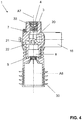
- the Figure 4 shows a sectional view through the first axis A7 and the second axis A8. It is easy to see here how the two axes A7 and A8 run collinear to one another.
- the deflection section 9 is oriented in this view in the direction of the smooth surface extending away from the same.
- a backflow preventer 33 is arranged in the inlet-side channel section 7.
- the flushing valve 1 here also has control cables 34 via which the valve 6 can be activated.
- the Figure 6 shows a first embodiment of a urinal arrangement with a flush valve 1 according to Figures 1 to 5 and a urinal 24.
- the urinal 24 has a receiving space 25 which has a drain opening 26 and a flushing water outlet opening 27 located above the closing opening 26. Opposite the receiving space 25, the urinal 24 has a cavity 32.
- the valve 7 protrudes with the outlet opening 5, here via the connection element 17, into the flushing water outlet opening 27.
- the urinals typically have an edge region 31 in the region of the flushing water outlet opening 27 which extends into the cavity 32 located behind the receiving space 25. Because of the deflection section 9, this edge area 31 can now be bypassed or the valve 6 is located in such a way that it does not collide with the edge area 31. That is, the valve 6 comes to rest in a position in the cavity 32, which is correspondingly free to accommodate the valve.
- the urinal 24 is correspondingly limited by an assembly level ME.
- the flushing valve is arranged in such a way that only the inlet opening 4 or the inlet-side connector 11 lies outside the rear space 32 delimited by the assembly plane ME.
- the mounting level ME is typically specified by a wall.
- the flush valve according to the invention has the advantage that the valve 6, which requires a comparatively large installation space, lies in the cavity 32 in such a way that the flush valve 1 as a whole lies essentially completely in the cavity 32.
- the valve 6 which requires a comparatively large installation space, lies in the cavity 32 in such a way that the flush valve 1 as a whole lies essentially completely in the cavity 32.
- the flush valve 1 as a whole lies essentially completely in the cavity 32.
- a method for assembling a urinal arrangement according to the first embodiment is characterized in that, in a first step, the flush valve is connected to the inlet opening 4 with a building-side water connection point, and that in a second step the urinal is assembled, with the urinal being assembled during assembly Outlet opening 5 comes to rest in the flushing water outlet opening 27.
- FIG. 7 another embodiment of the urinal assembly is shown.
- the urinal arrangement according to Figure 7 comprises a flushing valve as described above and a urinal 24 also as described above.
- a separate spray head 28 is also inserted into the flushing water outlet opening 27.
- the spray head 28 is connected to the outlet opening 5 of the flushing valve 1 by a hose 29.
- the flushing valve 1 is at a different location compared to the first embodiment, namely in the lower region.
- this arrangement has slight disadvantages compared to the arrangement of claim 1.
- this arrangement is used in corresponding urinals to be operated with a spray head.
- the main advantage is that for both arrangements according to the Figures 6 and 7th the same flush valve 1 can be used.
Abstract
Ein Spülventil (1), insbesondere ein Urinalspülventil, umfasstein Gehäuse (2) mit einem Wasserführungskanal (3) mit einer Einlassöffnung (4) und einer Auslassöffnung (5), undein den Wasserführungskanal (3) zwischen Einlassöffnung (4) und Auslassöffnung (5) sperrendes bzw. freigebendes Ventil (6),wobei sich der Wasserführungskanal (3) von der Einlassöffnung (4) mit einem einlassseitigen Kanalabschnitt (7) entlang einer ersten Achse (A7) erstreckt und zur Auslassöffnung (5) mit einem auslassseitigen Kanalabschnitt (8) entlang einer zweiten Achse (A8) erstreckt,wobei der Wasserführungskanal (3) zwischen dem einlassseitigen Kanalabschnitt (7) und dem auslassseitigen Kanalabschnitt (8) einen Umlenkabschnitt (9) aufweist, der sich in einem Winkel winklig geneigt zur ersten Achse (A7) und/oder zur zweiten Achse (A8) erstreckt, derart, dass der Umlenkabschnitt (9) bezüglich der Orientierung des einlassseitigen Kanalabschnitts (7) bzw. des auslassseitigen Kanalabschnitts (8) ausgelenkt ist, undwobei das Ventil (6) im besagten Umlenkabschnitt (9) angeordnet ist.A flush valve (1), in particular a urinal flush valve, comprises a housing (2) with a water duct (3) with an inlet opening (4) and an outlet opening (5), and into the water duct (3) between the inlet opening (4) and the outlet opening (5) blocking or releasing valve (6), the water guide channel (3) extending from the inlet opening (4) with an inlet-side channel section (7) along a first axis (A7) and to the outlet opening (5) with an outlet-side channel section (8) extends along a second axis (A8), wherein the water guide channel (3) between the inlet-side channel section (7) and the outlet-side channel section (8) has a deflection section (9) which is inclined at an angle to the first axis (A7) and / or extends to the second axis (A8) in such a way that the deflection section (9) is deflected with respect to the orientation of the inlet-side channel section (7) or the outlet-side channel section (8), and the valve (6) being arranged in said deflecting section (9).
Description
Die vorliegende Erfindung betrifft eine Spülventil, insbesondere ein Urinalspülventil, nach dem Oberbegriff von Anspruch 1 sowie eine Urinalanordnung nach den Ansprüchen 13 bzw. 16.The present invention relates to a flush valve, in particular a urinal flush valve, according to the preamble of
Aus der
Nachteilig an dieser Ausbildung ist der sehr hohe Montageaufwand, welcher im Wesentlichen durch das Anschliessen der Wasserschläuche motiviert ist. Die Kosten für derartige Anordnung sind demnach vergleichsweise hoch Zudem ist die Zahl der eigentlichen Anschlussstellen vergleichsweise hoch, was das Risiko von Leckage entsprechend erhöht.The disadvantage of this design is the very high installation effort, which is essentially motivated by the connection of the water hoses. The costs for such an arrangement are accordingly comparatively high. In addition, the number of actual connection points is comparatively high, which increases the risk of leakage accordingly.
Ausgehend von diesem Stand der Technik liegt der Erfindung eine Aufgabe zugrunde, ein Spülventil anzugeben, welches die Nachteile des Standes der Technik überwindet. Eine besonders bevorzugte Aufgabe ist es, ein Spülventil anzugeben, welches den Montageaufwand reduziert. Eine weitere besonders bevorzugte Aufgabe ist es, ein Spülventil anzugeben, welches möglichst vielseitig einsetzbar ist.Based on this prior art, the invention is based on an object of specifying a flush valve which overcomes the disadvantages of the prior art. A particularly preferred object is to specify a flush valve which reduces the assembly effort. Another particularly preferred object is to specify a flush valve which can be used as versatile as possible.
Diese Aufgabe wird durch das Spülventil von Anspruch 1 gelöst. Demgemäss umfasst ein Spülventil, insbesondere ein Urinalspülventil, ein Gehäuse mit einem Wasserführungskanal mit einer Einlassöffnung und einer Auslassöffnung, und ein den Wasserführungskanal zwischen Einlassöffnung und Auslassöffnung sperrendes bzw. freigebendes Ventil. Bei einer Spülung nimmt das Ventil die freigebende Stellung ein, so dass Spülwasser durch den Wasserführungskanal zur Auslassöffnung geführt werden kann. Der Wasserführungskanal erstreckt sich von der Einlassöffnung mit einem einlassseitigen Kanalabschnitt entlang einer ersten Achse. Weiter erstreckt sich der Wasserführungskanal zur Auslassöffnung mit einem auslassseitigen Kanalabschnitt entlang einer zweiten Achse. Der Wasserführungskanal weist zwischen dem einlassseitigen Kanalabschnitt und dem auslassseitigen Kanalabschnitt einen Umlenkabschnitt auf, der sich in einem Winkel winklig geneigt zur ersten Achse und/oder zur zweiten Achse erstreckt, derart, dass der Umlenkabschnitt bezüglich der Orientierung des einlassseitigen Kanalabschnitts bzw. des auslassseitigen Kanalabschnitts ausgelenkt ist. Das Ventil ist im besagten Umlenkabschnitt angeordnet.This object is achieved by the flush valve of
Durch die Anordnung des Umlenkabschnittes, welcher sich vom ersten Kanalabschnitt bzw. vom zweiten Kanalabschnitt auslenkt, ergeht der Vorteil, dass das Ventil an einem Ort platziert werden kann, an welchem im eingebauten Zustand in einem Urinal oder einem anderen Sanitärartikel mehr Raum besteht. Insbesondere kann bei einem Urinal das Spülventil derart eingebaut werden, dass das Ventil vom oberen Spülrand oder von der oberen Spüldüse gesehen, in einem unteren Raumbereich hinter dem allgemeinen Aufnahmeraum des Urinals zu liegen kommt. Diese unteren Raumbereiche sind aufgrund der Formgebung der Urinale mit grösseren Volumina ausgebildet, was mehr Raum für das Ventil schafft.The arrangement of the deflection section, which is deflected from the first channel section or from the second channel section, has the advantage that the valve can be placed at a location where there is more space in a urinal or other sanitary article when installed. In particular, in a urinal, the flush valve can be installed in such a way that the valve, viewed from the upper flushing rim or from the upper flushing nozzle, comes to lie in a lower spatial area behind the general receiving space of the urinal. Due to the shape of the urinals, these lower spatial areas are designed with larger volumes, which creates more space for the valve.
Das Ventil liegt, mit anderen Worten ausgedrückt, ausserhalb des einlassseitigen Kanalabschnitts bzw. des auslassseitigen Kanalabschnitts, wodurch das Ventil in einem Bereich am Sanitärartikel platziert werden kann, welcher einen grösseren Einbauraum bietet.In other words, the valve is located outside the inlet-side channel section or the outlet-side channel section, as a result of which the valve can be placed in an area on the sanitary article which offers a larger installation space.
In Einbaulage liegen die erste Achse und die zweite Achse im Wesentlichen in der Horizontalen. Der Umlenkabschnitt erstreckt sich vorzugweise in der Vertikalen.In the installed position, the first axis and the second axis are essentially in the Horizontal. The deflection section preferably extends vertically.
Der Umlenkabschnitt erstreckt sich vorzugsweise in einem Winkel von 90° zur ersten Achse bzw. zur zweiten Achse.The deflection section preferably extends at an angle of 90 ° to the first axis or to the second axis.
Vorzugsweise liegen die erste Achse und die zweite Achse in einer gemeinsamen Ebene und verlaufen insbesondere kollinear zueinander.The first axis and the second axis preferably lie in a common plane and, in particular, run collinear to one another.
Dies hat den Vorteil, dass der Einlassöffnung und die Auslassöffnung in Einbaulage auf der gleichen Höhe angeordnet werden können, was bei der Montage eines Urinals von Vorteil ist. Insbesondere kann zuerst das Spülventil mit einer gebäudeseitigen Wasserleitung verbunden werden und anschliessend kann das Urinal mit dem Spülventil verbunden werden.This has the advantage that the inlet opening and the outlet opening can be arranged at the same height in the installed position, which is advantageous when installing a urinal. In particular, the flush valve can first be connected to a building-side water pipe and then the urinal can be connected to the flush valve.
Vorzugsweise weist der Umlenkabschnitt einen ersten Teilabschnitt und einen sich dem ersten Teilabschnitt anschliessenden zweiten Teilabschnitt auf, wobei der erste Teilabschnitt vom einlassseitigen Kanalabschnitt wegführt und der zweite Teilabschnitt zum auslassseitigen Kanalabschnitt hinführt, wobei die beiden Teilabschnitte parallel zueinander verlaufen. Die beiden Teilabschnitte verlaufen vorzugsweise rechtwinklig zu den beiden Kanalabschnitten.The deflection section preferably has a first section and a second section adjoining the first section, the first section leading away from the inlet-side channel section and the second section leading to the outlet-side channel section, the two subsections running parallel to one another. The two subsections preferably run at right angles to the two channel sections.
Mit anderen Worten kann gesagt werden, dass der Umlenkabschnitt im Wesentlichen U-förmig ausgebildet ist.In other words, it can be said that the deflection section is essentially U-shaped.
In einer Variante ist das Ventil ein Magnetventil, insbesondere mit einer elektrisch ansteuerbaren Membran. Das Magnetventil bzw. die Membran kann dabei von einem geschlossenen Zustand in einen offenen Zustand gebracht werden. Im letzteren Zustand wird der Wasserführungskanal freigegeben.In one variant, the valve is a solenoid valve, in particular with an electrically controllable membrane. The solenoid valve or the membrane can be brought from a closed state into an open state. In the latter state, the water channel is released.
Vorzugsweise liegt das Magnetventil bzw. die Membran möglichst weit von den beiden Kanalabschnitten entfernt.The solenoid valve or the membrane is preferably located as far away as possible from the two channel sections.
In einer anderen Variante weist das Ventil einen Ventilstössel auf, welcher mit einem im Umlenkabschnitt liegenden Ventilsitz zusammenarbeitet. Der Ventilsitz wird vorzugsweise durch Seitenwände des Umlenkabschnittes bereitgestellt.In another variant, the valve has a valve stem, which with an im Deflection section lying valve seat cooperates. The valve seat is preferably provided by side walls of the deflection section.
Vorzugsweise liegt der Ventilsitz möglichst weit von beiden Kanalabschnitten entfernt.The valve seat is preferably located as far away as possible from both channel sections.
Besonders bevorzugt liegt der Ventilsitz im ersten Teilabschnitt oder im zweiten Teilabschnitt, wobei der Ventilstössel parallel zur Mittelachse des jeweiligen Teilabschnittes orientiert ist.The valve seat is particularly preferably located in the first section or in the second section, the valve stem being oriented parallel to the central axis of the respective section.
Bei einer Anordnung des Ventilsitzes im ersten Teilabschnitt ragt der Ventilstössel gegen die Fliessrichtung in den ersten Teilabschnitt ein. Bei einer Anordnung des Ventilsitzes im zweiten Teilabschnitt ragt der Ventilstössel in die Fliessrichtung in den zweiten Teilabschnitt ein.When the valve seat is arranged in the first section, the valve stem protrudes into the first section against the direction of flow. When the valve seat is arranged in the second subsection, the valve stem protrudes into the second subsection in the direction of flow.
Vorzugsweise wird der Ventilstössel entlang einer Längsbewegung relativ zum Ventilsitz bewegt. Eine Drehbewegung ist aber auch denkbar.The valve stem is preferably moved along a longitudinal movement relative to the valve seat. However, a rotary movement is also conceivable.
Vorzugsweise liegt das Ventil mit der Massgabe eines grösstmöglichen Abstandes zwischen dem Ventil und der ersten Achse und/oder der zweiten Achse im Umlenkabschnitt.The valve is preferably located in the deflection section with the greatest possible distance between the valve and the first axis and / or the second axis.
Dadurch ergeht der Vorteil, dass das Spülventil für möglichst viele Urinalformen einsetzbar ist, weil das Ventil so in Bereiche der Urinale zu liegen kommt, welche typischerweise als freie Hohlräume ausgebildet sind.This has the advantage that the flush valve can be used for as many forms of urinals as possible, because the valve comes to rest in areas of the urinals which are typically designed as free cavities.
Vorzugsweise liegt das Ventil in einem Abstand quer zur ersten Achse und/oder zur zweiten Achse von mindestens 8 Zentimetern, insbesondere von mindestens 12 Zentimetern, von der ersten Achse und/oder der zweiten Achse entfernt.The valve is preferably at a distance transverse to the first axis and / or to the second axis of at least 8 centimeters, in particular of at least 12 centimeters, from the first axis and / or the second axis.
Vorzugsweise weist das Gehäuse einen Hauptgehäuseabschnitt auf, in welchem sich der Umlenkabschnitt erstreckt, wobei sich quer zum Hauptgehäuseabschnitt ein einlassseitiger Anschlussstutzen mit der Einlassöffnung und ein auslassseitiger Anschlussstutzen mit der Auslassöffnung erstreckt.The housing preferably has a main housing section in which the deflecting section extends, an inlet-side connection piece with the inlet opening and an outlet-side connection piece with the outlet opening extending transversely to the main housing section.
Der Hauptgehäuseabschnitt ist vorzugsweise länglich ausgebildet, wobei die beiden Anschlussstutzen an einem Ende des länglich ausgebildeten Hauptgehäuseabschnitts angeordnet sind. Hierdurch kann ebenfalls den knappen Platzverhältnissen Rechnung getragen werden.The main housing section is preferably elongated, the two connecting pieces being arranged at one end of the elongated main housing section. In this way, the limited space can also be taken into account.
Vorzugsweise weist der Hauptgehäuseabschnitt an einer gegenüber dem Anschlussstutzen liegenden Stirnseite eine Aufnahme auf, in welche das Ventil eingesetzt ist.The main housing section preferably has a receptacle, in which the valve is inserted, on an end face opposite the connection piece.
Vorzugsweise weist die Aufnahme einen zylindrischen Querschnitt auf. Das Ventil weist einen zylindrischen Lagerabschnitt auf, welcher in die Aufnahme einragt. Durch diese Ausbildung kann das Ventil vergleichsweise einfach mit dem Gehäuse verbunden bzw. im Wartungsfall vom Gehäuse getrennt werden.The receptacle preferably has a cylindrical cross section. The valve has a cylindrical bearing section which protrudes into the receptacle. As a result of this design, the valve can be connected to the housing in a comparatively simple manner or separated from the housing in the event of maintenance.
Vorzugsweise weist der Hauptgehäuseabschnitt einen gegenüber dem Bereich, in welchem das Ventil liegt, verjüngten Querschnitt auf, wobei sich die beiden Anschlussstutzen vom verjüngten Querschnitt weg erstrecken.The main housing section preferably has a cross section which is tapered in relation to the area in which the valve is located, the two connecting pieces extending away from the tapered cross section.
Durch den verjüngten Querschnitt ergeht der Vorteil, dass Hauptgehäuse zwischen den Anschlussstutzen und dem Ventil möglichst schlank ausgebildet ist, wodurch es vielseitig einsetzbar wird.The tapered cross-section has the advantage that the main housing between the connecting piece and the valve is designed to be as slim as possible, which makes it versatile.
Vorzugsweise weist das Spülventil weiterhin ein Absperrventil auf, welches im Umlenkabschnitt in Fliessrichtung vor dem Ventil gesehen, angeordnet ist. Im Wartungsfall kann das Absperrventil geschlossen werden, wodurch das Ventil "wasserlos" wird und daher ohne unkontrollierten Wasseraustritt aus dem Gehäuse entfernt werden kann. Das Absperrventil kann auch zur Drosselung des Durchflusses eingesetzt werden. Beispielsweise mit dem Ziel, das Spülwasser mit entsprechenden Strömungsverhältnissen dem Sanitärartikel zuzuführen, so dass es nicht zu einem Überschiessen des Spülwassers kommen kann.The flushing valve preferably also has a shut-off valve, which is arranged in the deflecting section in front of the valve in the direction of flow. In the event of maintenance, the shut-off valve can be closed, whereby the valve becomes "waterless" and can therefore be removed from the housing without uncontrolled water leakage. The shut-off valve can also be used to restrict the flow. For example, with the aim of feeding the rinsing water to the sanitary article with appropriate flow conditions so that the rinsing water cannot overflow.
Vorzugsweise weist das Spülventil weiterhin ein separat zum Spülventil ausgebildetes Anschlusselement aus, welches mit dem auslassseitigen Anschlussstutzen verbindbar ist, wobei der auslassseitige Anschlussstutzen vorzugsweise ein Aussengewinde und das Anschlusselement vorzugsweise ein Innengewinde aufweist, über welche Gewinde die Verbindung zwischen dem Anschlusselement und dem Gehäuse hergestellt wird.The flushing valve preferably also has a connection element which is formed separately from the flushing valve and which can be connected to the outlet-side connection piece, wherein the outlet-side connection piece preferably has an external thread and the connection element preferably has an internal thread, via which thread the connection between the connection element and the housing is established.
Das Anschlusselement weist den Vorteil auf, dass der auslassseitige Anschlussstutzen verlängert werden kann.The connection element has the advantage that the connection piece on the outlet side can be extended.
Besonders bevorzugt ist das Anschlusselement in seiner Länge veränderbar ausgebildet, so dass das Anschlusselement auf die entsprechend gewünschte Länge gekürzt werden kann.The length of the connecting element is particularly preferably designed to be changeable, so that the connecting element can be shortened to the correspondingly desired length.
Vorzugsweise weist das Anschlusselement weiterhin eine Dichtung auf, mit welcher das Anschlusselement gegenüber einer Spülwasseraustrittsöffnung am Sanitärartikel abgedichtet werden kann.The connection element preferably furthermore has a seal with which the connection element can be sealed off from a flushing water outlet opening on the sanitary article.
Eine Urinalanordnung umfasst ein Spülventil nach obiger Beschreibung und ein Urinal mit einem Aufnahmeraum, der eine Abflussöffnung und eine oberhalb der Abflussöffnung liegende Spülwasseraustrittsöffnung aufweist, wobei das Spülventil mit der Auslassöffnung direkt in die Spülwasseraustrittsöffnung einragt. Weiter liegt das Spülventil in einem Hohlraum gegenüber dem Aufnahmeraum.A urinal arrangement comprises a flush valve as described above and a urinal with a receiving space which has a drain opening and a flush water outlet opening located above the drain opening, the flush valve with the outlet opening protruding directly into the flush water outlet opening. The flushing valve is also located in a cavity opposite the receiving space.
Vorzugsweise weist das Urinal eine rückseitig liegende und den Aufnahmeraum rückseitig begrenzende Montageebene auf, wobei das Ventil derart angeordnet ist, dass ausschliesslich die Einlassöffnung ausserhalb des durch die Montageebene begrenzten Aufnahmeraums liegt. Die restlichen Elemente bzw. Bereiche des Spülventils liegen demnach im inneren des Aufnahmeraums.The urinal preferably has a mounting plane located on the rear and delimiting the receiving space on the rear, the valve being arranged in such a way that only the inlet opening lies outside the receiving space delimited by the mounting plane. The remaining elements or areas of the flush valve are accordingly located in the interior of the receiving space.
Ein Verfahren zur Montage einer Urinalanordnung nach obiger Beschreibung ist dadurch charakterisiert,
- dass in einem ersten Schritt, das Spülventil mit der Einlassöffnung mit einer gebäudeseitigen Wasseranschlussstelle verbunden wird, und
- dass in einem zweiten Schritt das Urinal montiert, wobei während der Montage des Urinals die Auslassöffnung in die Spülwasseraustrittsöffnung zu liegen kommt.
- that in a first step, the flush valve is connected to the inlet opening with a building-side water connection point, and
- that in a second step the urinal is assembled, the outlet opening coming to lie in the flushing water outlet opening during the assembly of the urinal.
Eine weitere Urinalanordnung umfasst ein Spülventil nach obiger Beschreibung und ein Urinal mit einem Aufnahmeraum, der eine Abflussöffnung und eine oberhalb der Abflussöffnung liegende Spülwasseraustrittsöffnung aufweist, wobei ein separater Sprühkopf in die Spülwasseraustrittsöffnung eingesetzt ist, welcher mit einem Schlauch mit der Auslassöffnung verbunden ist. Weiter liegt das Spülventil in einem Hohlraum gegenüber des Aufnahmeraums.Another urinal arrangement comprises a flush valve as described above and a urinal with a receiving space which has a drain opening and a flush water outlet opening located above the drain opening, a separate spray head being inserted into the flush water outlet opening, which is connected to the outlet opening by a hose. The flushing valve is also located in a cavity opposite the receiving space.
Ein Verfahren zur Montage einer Urinalanordnung nach der zweiten Ausführungsform, dadurch charakterisiert, dass in einem ersten Schritt, die Spülventil mit der Einlassöffnung mit einer gebäudeseitigen Wasseranschlussstelle verbunden wird, und dass in einem zweiten Sprühkopf in die Spülwasseraustrittsöffnung eingesetzt wird, welcher anschliessend mit einem Schlauchmit der Auslassöffnung des Spülventils verbunden wird.A method for assembling a urinal arrangement according to the second embodiment, characterized in that, in a first step, the flushing valve is connected to the inlet opening with a building-side water connection point, and that a second spray head is inserted into the flushing water outlet opening, which is then connected to a hose with the Outlet opening of the flush valve is connected.
Weitere Ausführungsformen sind in den abhängigen Ansprüchen angegeben.Further embodiments are given in the dependent claims.
Bevorzugte Ausführungsformen der Erfindung werden im Folgenden anhand der Zeichnungen beschrieben, die lediglich zur Erläuterung dienen und nicht einschränkend auszulegen sind. In den Zeichnungen zeigen:
- Fig. 1
- eine perspektivische Ansicht einer Ausführungsform des erfindungsgemässen Spülventils;
- Fig. 2
- eine Explosionsdarstellung des Spülventils nach
Figur 1 ; - Fig. 3
- eine Schnittdarstellung des Spülventils nach
Figur 1 ; - Fig. 4
- eine weitere Schnittdarstellung des Spülventils nach
Figur 1 ; - Fig. 5
- eine weitere Schnittdarstellung des Spülventils nach
Figur 1 ; - Fig. 6
- eine Schnittdarstellung durch eine Urinalanordnung nach einer ersten Ausführung mit einem Urinal und einem Spülventil nach den vorhergehenden Figuren; und
- Fig. 7
- eine Schnittdarstellung durch eine Urinalanordnung nach einer zweiten Ausführung mit einem Urinal und einem Spülventil nach den vorhergehenden Figuren.
- Fig. 1
- a perspective view of an embodiment of the flush valve according to the invention;
- Fig. 2
- an exploded view of the flush valve according to
Figure 1 ; - Fig. 3
- a sectional view of the flush valve according to
Figure 1 ; - Fig. 4
- a further sectional view of the flush valve according to
Figure 1 ; - Fig. 5
- a further sectional view of the flush valve according to
Figure 1 ; - Fig. 6
- a sectional view through a urinal arrangement according to a first embodiment with a urinal and a flush valve according to the preceding figures; and
- Fig. 7
- a sectional view through a urinal arrangement according to a second embodiment with a urinal and a flush valve according to the preceding figures.
In den
Das Spülventil 1 umfasst ein Gehäuse 2 mit einem Wasserführungskanal 3 mit einer Einlassöffnung 4 und einer Auslassöffnung 5. Weiter ist im Wasserführungskanal 3 ein den Wasserführungskanal 3 zwischen Einlassöffnung 4 und Auslassöffnung 5 sperrendes bzw. freigebendes Ventil 6 angeordnet. Im Wasserführungskanal 3 strömt das Spülwasser somit von der Einlassöffnung zu der Auslassöffnung 5 und das Ventil 6 unterbricht den Wasserführungskanal 3 bzw. gibt den Wasserführungskanal 3 bei einem Spülvorgang entsprechend frei.The flushing
Der Wasserführungskanal 3 erstreckt sich von der Einlassöffnung 4 her gesehen mit einem einlassseitigen Kanalabschnitt 7 entlang einer ersten Achse A7. Zur Auslassöffnung 5 hin erstreckt sich der Wasserführungskanal 3 mit einem auslassseitigen Kanalabschnitt 8 entlang einer zweiten Ache A8. Der Wasserführungskanal 3 weist weiter zwischen dem einlassseitigen Kanalabschnitt 7 und dem auslassseitigen Kanalabschnitt 8 einen Umlenkabschnitt 9 auf. Der Umlenkabschnitt 9 erstreckt sich in einem Winkel winklig geneigt zur ersten Achse A7 und/oder zur zweiten Achse A8. Dabei erstreckt sich der Umlenkabschnitt 9 derart zur ersten Achse A7 bzw. zur zweiten Achse A8, dass der Umlenkabschnitt 9 bezüglich der Orientierung des einlassseitigen Kanalabschnitts 7 bzw. des auslassseitigen Kanalabschnitts 8 ausgelenkt wird. Diese Auslenkung wird in der Schnittdarstellung der
In der gezeigten Ausführungsform liegen die erste Achse A7 und die zweiten Achse A8 in einer gemeinsamen Ebene E und verlaufen hier kollinear zueinander. Der Umlenkabschnitt 9 ist dabei zu den beiden Achsen A7, A8 entsprechend ausgelenkt.In the embodiment shown, the first axis A7 and the second axis A8 lie in a common plane E and here run collinear to one another. The
Der Umlenkabschnitt 6 weist einen ersten Teilabschnitt 20 und einen sich dem ersten Teilabschnitt 20 anschliessenden zweiten Teilabschnitt 21 auf. Der erste Teilabschnitt 20 führt vom einlassseitigen Kanalabschnitt 7 weg. Der zweite Teilabschnitt 21 führt zum auslassseitigen Kanalabschnitt 8 hin. Die beiden Teilabschnitte 20, 21 verlaufen parallel zueinander. Die beiden Teilabschnitte 20, 21 sind dabei zu dem einlassseitigen Kanalabschnitt 7 bzw. zu dem auslassseitigen Kanalabschnitt 8 winklig geneigt orientiert. Hier verlaufen die Teilabschnitte 20, 21 in einem rechten Winkel zu den Kanalabschnitten 7, 8.The deflecting
Im Bereich des Übergangs vom ersten Teilabschnitt 20 zum zweiten Teilabschnitt 21 ist das Ventil 6 angeordnet. Das Ventil 6 befindet sich hier in einem grösstmöglichen Abstand zum einlassseitigen Kanalabschnitt 7 bzw. zum auslassseitigen Kanalabschnitt 8.The
Das Ventil ist in der gezeigten Ausführungsform ein Magnetventil. Das Magnetventil weist vorzugsweise eine elektrisch ansteuerbare Membran auf, welche den Spülwasserkanal sperrt bzw. frei gibt. Das Magnetventil ragt in der gezeigten Ausführungsform mit einem Rohransatz 22 in eine Aufnahme 23 am Umlenkabschnitt 9 ein. Die Membran selbst ist nicht gezeigt. Die Membran befindet sich im Inneren des Magnetventils unterhalb des Rohransatzes 22.In the embodiment shown, the valve is a solenoid valve. The solenoid valve preferably has an electrically controllable membrane that blocks or opens the flushing water channel. In the embodiment shown, the solenoid valve protrudes with a
In einer nicht gezeigten Ausführungsform weist das Ventil 6 weist einen Ventilstössel auf, welcher mit einem im Umlenkabschnitt 9 liegenden Ventilsitz zusammenarbeitet. Der Ventilsitz liegt vorzugsweise im zweiten Teilabschnitt 21. Beispielsweise ragt der Ventilstössel in Richtung der Mittelachse M21 des zweiten Teilabschnittes 21 in den zweiten Teilabschnitt 21 ein und arbeitet dort mit dem Ventilsitz, der an den Wänden des zweiten Teilabschnittes 21 angeordnet ist, zusammen. Der Ventilstössel ist demnach parallel zur Mittelachse M21 des zweiten Teilabschnittes 21 angeordnet und lässt sich vorzugsweise in Richtung der Mittelachse M21 bewegen.In an embodiment not shown, the
In alternativen Ausführungsformen wäre es auch denkbar, dass der Ventilsitz im ersten Umlenkabschnitt 20 liegt.In alternative embodiments it would also be conceivable that the valve seat lies in the
Grundsätzlich ist das Ventil 6, unabhängig von seiner Bauart, mit der Massgabe eines grösstmöglichen Abstand A zwischen dem Ventil 6 und der ersten Achse A7 bzw. der zweiten Achse A8 im Umlenkabschnitt 9 angeordnet. Der Abstand trägt das Bezugszeichen Z und ist in der
Vorzugsweise ist der Abstand Z quer zur ersten Achse A7 bzw. zur zweiten Achse A8 mindestens 8 Zentimetern, insbesondere mindestens 12 Zentimeter. Das heisst, das Ventil 6 liegt in einem entsprechenden Abstand von der ersten Achse A7 bzw. von der zweiten Achse A8 entfernt.Preferably, the distance Z across the first axis A7 or the second axis A8 is at least 8 centimeters, in particular at least 12 centimeters. This means that the
Das Gehäuse 2 weist, wie in den Figuren gezeigt, einen Hauptgehäuseabschnitt 10 auf. Im Hauptgehäuseabschnitt 10 erstreckt sich der Umlenkabschnitt 9. Quer zum Hauptgehäuseabschnitt 10 erstreckt sich ein einlassseitiger Anschlussstutzen 11 mit der Einlassöffnung 4 und dem einlassseitigen Kanalabschnitt 7. Ebenfalls quer zum Hauptgehäuseabschnitt 10 erstreckt sich ein auslassseitiger Anschlussstutzen 12 mit der Auslassöffnung 7 sowie dem auslassseitigen Kanalabschnitt 8.As shown in the figures, the
Der einlassseitige Anschlussstutzen 11 dient dem Anschluss des Spülventiles 1 an eine Wasserleitung. Der auslassseitige Anschlussstutzen 12 dient dem Anschluss des Spülventils 1 an einen Sanitärartikel. Beispielsweise können hierzu die Anschlussstutzen 10, 11 mit Gewinden versehen sein.The inlet-
Weiter weist der Hauptgehäuseabschnitt 10 an einer gegenüber den Anstossstolzen 11, 12 liegenden Stirnseite 13 eine Aufnahme 14 auf. In die Aufnahme 14 ist das Ventil 6 eingesetzt. Die Aufnahme 14 weist einen zylindrischen Querschnitt auf. Das Ventil 6 weist weiter einen zylindrischen Lagerabschnitt 35 auf, welcher in die Aufnahme 14 entsprechend einragt. Weiter ist in der gezeigten Ausführungsform die Aufnahme 14 für das Ventil 6 als Unterbruch der Gehäusewand im Umlenkabschnitt 9 ausgebildet. Das Ventil 6 wird dabei als Teil der den Umlenkabschnitt 9 umgebenden Wandung in die Aufnahme eingesetzt.The
Weiter weist der Hauptgehäuseabschnitt 10 einen gegenüber dem Bereich, in welchem das Ventil 6 liegt, verjüngten Querschnitt 15 auf. Der verjüngte Querschnitt 15 bildet einen entsprechenden dünneren Querschnitt, so dass das Spülventil 1 an die Einbausituation besser angepasst ist. Die Verjüngung des verjüngten Querschnitts 15 ist in der
Von den
Weiter weist das Spülventil 1 ein separat zum Spülventil 1 ausgebildetes Anschlusselement 17 auf, welches mit dem auslassseitigen Anschlussstutzen 12 verbindbar ist. Der auslassseitige Anschlussstutzen 12 weist in der gezeigten Ausführungsform ein Aussengewinde 18 auf. Das Anschlusselement 17 weist weiterhin ein Innengewinde 19 auf. Über die Gewinde 18, 19 lässt sich eine Verbindung zwischen dem Abschlusselement 17 und dem Gehäuse 2 herstellen.The flushing
Aussenseitig umfasst das Anschlusselement 17 eine Dichtmanschette 30. Über die Dichtmanschette 30 kann das Anschlusselement 17 gegenüber einem Sanitärartikel entsprechend abgedichtet werden.On the outside, the
Das Anschlusselement 17 kann weiterhin kürzbar ausgebildet sein. In diesem Fall ist die Dichtmanschette 30 vor einer entsprechenden Kürzung des Anschlusselementes 17 entsprechend zu entfernen, sodass der Bereich, in welchem die Dichtmanschette 30 liegt, gekürzt werden kann. Anschliessend kann die Dichtmanschette 30 erneut montiert werden.The
Die
Von der
Das Spülventil 1 weist hier weiter Steuerkabel 34 auf, über welche das Ventil 6 angesteuert werden kann.The flushing
Die
Das Ventil 7 ragt mit der Auslassöffnung 5, hier über das Anschlusselement 17, in die Spülwasseraustrittsöffnung 27 ein. In der gezeigten Ausführungsform kann gut erkannt werden, dass die Urinale typischerweise im Bereich der Spülwasseraustrittsöffnung 27 einen Randbereich 31 aufweisen, welche sich in den hinter den Aufnahmeraum 25 liegenden Hohlraum 32 erstreckt. Aufgrund des Umlenkabschnittes 9 kann nun dieser Randbereich 31 umgangen werden bzw. das Ventil 6 liegt dabei derart, dass dieses nicht mit dem Randbereich 31 kollidiert. Das heisst, das Ventil 6 kommt an einer Lage im Hohlraum 32 zu liegen, welche entsprechend frei ist, um das Ventil aufzunehmen. Rückseitig wird das Urinal 24 durch eine Montageebene ME entsprechend begrenzt. Das Spülventil ist dabei derart angeordnet, dass ausschliesslich die Einlassöffnung 4 beziehungsweise der einlassseitige Anschlussstutzen 11 ausserhalb des durch die Montageebene ME begrenzten Rückraums 32 liegt. Die Montageebene ME wird typischerweise durch eine Wand vorgegeben.The
Mit Blick auf die
Ein Verfahren zur Montage einer Urinalanordnung nach der ersten Ausführungsform ist dadurch charakterisiert, dass in einem ersten Schritt, die Spülventil mit der Einlassöffnung 4 mit einer gebäudeseitigen Wasseranschlussstelle verbunden wird, und dass in einem zweiten Schritt das Urinal montiert, wobei während der Montage des Urinals die Auslassöffnung 5 in die Spülwasseraustrittsöffnung 27 zu liegen kommt.A method for assembling a urinal arrangement according to the first embodiment is characterized in that, in a first step, the flush valve is connected to the
In der
Claims (17)
ein Gehäuse (2) mit einem Wasserführungskanal (3) mit einer Einlassöffnung (4) und einer Auslassöffnung (5), und
ein den Wasserführungskanal (3) zwischen Einlassöffnung (4) und Auslassöffnung (5) sperrendes bzw. freigebendes Ventil (6),
wobei sich der Wasserführungskanal (3) von der Einlassöffnung (4) mit einem einlassseitigen Kanalabschnitt (7) entlang einer ersten Achse (A7) erstreckt und zur Auslassöffnung (5) mit einem auslassseitigen Kanalabschnitt (8) entlang einer zweiten Achse (A8) erstreckt,
wobei der Wasserführungskanal (3) zwischen dem einlassseitigen Kanalabschnitt (7) und dem auslassseitigen Kanalabschnitt (8) einen Umlenkabschnitt (9) aufweist, der sich in einem Winkel winklig geneigt zur ersten Achse (A7) und/oder zur zweiten Achse (A8) erstreckt, derart, dass der Umlenkabschnitt (9) bezüglich der Orientierung des einlassseitigen Kanalabschnitts (7) bzw. des auslassseitigen Kanalabschnitts (8) ausgelenkt ist, und
wobei das Ventil (6) im besagten Umlenkabschnitt (9) angeordnet ist.Flush valve (1), in particular a urinal flush valve, comprising
a housing (2) with a water guiding channel (3) with an inlet opening (4) and an outlet opening (5), and
a valve (6) blocking or releasing the water duct (3) between inlet opening (4) and outlet opening (5),
wherein the water guiding channel (3) extends from the inlet opening (4) with an inlet-side channel section (7) along a first axis (A7) and to the outlet opening (5) with an outlet-side channel section (8) along a second axis (A8),
wherein the water guide channel (3) between the inlet-side channel section (7) and the outlet-side channel section (8) has a deflection section (9) which extends at an angle inclined at an angle to the first axis (A7) and / or to the second axis (A8) , in such a way that the deflecting section (9) is deflected with respect to the orientation of the inlet-side channel section (7) or the outlet-side channel section (8), and
the valve (6) being arranged in said deflecting section (9).
Priority Applications (2)
| Application Number | Priority Date | Filing Date | Title |
|---|---|---|---|
| EP19167022.3A EP3719226B1 (en) | 2019-04-03 | 2019-04-03 | Flush valve |
| CH01621/19A CH715567B1 (en) | 2019-04-03 | 2019-12-13 | Flush valve. |
Applications Claiming Priority (1)
| Application Number | Priority Date | Filing Date | Title |
|---|---|---|---|
| EP19167022.3A EP3719226B1 (en) | 2019-04-03 | 2019-04-03 | Flush valve |
Publications (2)
| Publication Number | Publication Date |
|---|---|
| EP3719226A1 true EP3719226A1 (en) | 2020-10-07 |
| EP3719226B1 EP3719226B1 (en) | 2022-10-05 |
Family
ID=66092048
Family Applications (1)
| Application Number | Title | Priority Date | Filing Date |
|---|---|---|---|
| EP19167022.3A Active EP3719226B1 (en) | 2019-04-03 | 2019-04-03 | Flush valve |
Country Status (2)
| Country | Link |
|---|---|
| EP (1) | EP3719226B1 (en) |
| CH (1) | CH715567B1 (en) |
Citations (5)
| Publication number | Priority date | Publication date | Assignee | Title |
|---|---|---|---|---|
| GB2201699A (en) * | 1987-02-23 | 1988-09-07 | John Lloyd Parry Jones | Automatically flushing urinal |
| EP0348864A1 (en) * | 1988-06-25 | 1990-01-03 | Toto Ltd. | Water urinal |
| DE4120768A1 (en) | 1991-06-24 | 1993-01-14 | Duravit Ag | Wall urinal with rearwards flushing water inlet and outlet connections - has water input and/or outlet connection adjustable in height |
| DE202006008667U1 (en) | 2006-05-30 | 2006-08-10 | Dallmer Gmbh & Co. Kg | Urinal is fitted with water connection and drain for a modular assembly onto the selected site |
| US20170284075A1 (en) * | 2016-04-01 | 2017-10-05 | Transcendent Holdings LLC | Flush System for a Toilet |
-
2019
- 2019-04-03 EP EP19167022.3A patent/EP3719226B1/en active Active
- 2019-12-13 CH CH01621/19A patent/CH715567B1/en unknown
Patent Citations (5)
| Publication number | Priority date | Publication date | Assignee | Title |
|---|---|---|---|---|
| GB2201699A (en) * | 1987-02-23 | 1988-09-07 | John Lloyd Parry Jones | Automatically flushing urinal |
| EP0348864A1 (en) * | 1988-06-25 | 1990-01-03 | Toto Ltd. | Water urinal |
| DE4120768A1 (en) | 1991-06-24 | 1993-01-14 | Duravit Ag | Wall urinal with rearwards flushing water inlet and outlet connections - has water input and/or outlet connection adjustable in height |
| DE202006008667U1 (en) | 2006-05-30 | 2006-08-10 | Dallmer Gmbh & Co. Kg | Urinal is fitted with water connection and drain for a modular assembly onto the selected site |
| US20170284075A1 (en) * | 2016-04-01 | 2017-10-05 | Transcendent Holdings LLC | Flush System for a Toilet |
Also Published As
| Publication number | Publication date |
|---|---|
| EP3719226B1 (en) | 2022-10-05 |
| CH715567B1 (en) | 2020-05-29 |
Similar Documents
| Publication | Publication Date | Title |
|---|---|---|
| EP2525126B1 (en) | Connector for a heatable fluid conduit and heatable fluid conduit | |
| EP3690155B1 (en) | Fitting assembly | |
| DE202011100879U1 (en) | Transition piece | |
| EP3064663B1 (en) | Sanitary device | |
| DE102008032687B4 (en) | Fastening arrangement for sanitary components through which water flows | |
| DE602004001438T2 (en) | Outlet channel, in particular for support strut of jet engines | |
| EP3719226B1 (en) | Flush valve | |
| DE102018113818B9 (en) | Extractor system | |
| EP3263782A1 (en) | Inlet fitting | |
| AT503638B1 (en) | HOLLOW BODY FOR CONCRETE CONSTRUCTION INSTALLATION | |
| EP3199715B1 (en) | Overflow for a basin, in particular rinsing basin | |
| EP2284068A2 (en) | Hydraulic telescope seat post | |
| EP3364119B1 (en) | Deviating element | |
| WO2021009093A1 (en) | Discharge connection for the separated discharge of fluids of different densities | |
| EP3919792B1 (en) | Valve body | |
| DE102018106334A1 (en) | Nozzle arrangement for a field sprayer | |
| EP2921596B1 (en) | Drain valve | |
| EP3896234A1 (en) | Fitting assembly | |
| EP3647504B1 (en) | Sanitary item arrangement | |
| CH568505A5 (en) | Water distribution valve with inclined seat - has seat centre between planes enclosing thickened portion of housing | |
| EP3910118A1 (en) | Drain assembly | |
| DE202020102705U1 (en) | Cable outlet element for electrical installation as well as assembly system for electrical installation consisting of a cable outlet element and a terminating element | |
| EP4043652A1 (en) | Pipe interrupter and flushing system equipped therewith | |
| EP0859094A1 (en) | Manhole shaft system and introducing guide | |
| EP4253674A1 (en) | Pipe interrupter and flushing system equipped therewith |
Legal Events
| Date | Code | Title | Description |
|---|---|---|---|
| PUAI | Public reference made under article 153(3) epc to a published international application that has entered the european phase |
Free format text: ORIGINAL CODE: 0009012 |
|
| STAA | Information on the status of an ep patent application or granted ep patent |
Free format text: STATUS: THE APPLICATION HAS BEEN PUBLISHED |
|
| AK | Designated contracting states |
Kind code of ref document: A1 Designated state(s): AL AT BE BG CH CY CZ DE DK EE ES FI FR GB GR HR HU IE IS IT LI LT LU LV MC MK MT NL NO PL PT RO RS SE SI SK SM TR |
|
| AX | Request for extension of the european patent |
Extension state: BA ME |
|
| STAA | Information on the status of an ep patent application or granted ep patent |
Free format text: STATUS: REQUEST FOR EXAMINATION WAS MADE |
|
| 17P | Request for examination filed |
Effective date: 20210209 |
|
| RBV | Designated contracting states (corrected) |
Designated state(s): AL AT BE BG CH CY CZ DE DK EE ES FI FR GB GR HR HU IE IS IT LI LT LU LV MC MK MT NL NO PL PT RO RS SE SI SK SM TR |
|
| GRAP | Despatch of communication of intention to grant a patent |
Free format text: ORIGINAL CODE: EPIDOSNIGR1 |
|
| STAA | Information on the status of an ep patent application or granted ep patent |
Free format text: STATUS: GRANT OF PATENT IS INTENDED |
|
| INTG | Intention to grant announced |
Effective date: 20220502 |
|
| GRAS | Grant fee paid |
Free format text: ORIGINAL CODE: EPIDOSNIGR3 |
|
| GRAA | (expected) grant |
Free format text: ORIGINAL CODE: 0009210 |
|
| STAA | Information on the status of an ep patent application or granted ep patent |
Free format text: STATUS: THE PATENT HAS BEEN GRANTED |
|
| AK | Designated contracting states |
Kind code of ref document: B1 Designated state(s): AL AT BE BG CH CY CZ DE DK EE ES FI FR GB GR HR HU IE IS IT LI LT LU LV MC MK MT NL NO PL PT RO RS SE SI SK SM TR |
|
| REG | Reference to a national code |
Ref country code: GB Ref legal event code: FG4D Free format text: NOT ENGLISH |
|
| REG | Reference to a national code |
Ref country code: CH Ref legal event code: EP |
|
| REG | Reference to a national code |
Ref country code: AT Ref legal event code: REF Ref document number: 1522843 Country of ref document: AT Kind code of ref document: T Effective date: 20221015 |
|
| REG | Reference to a national code |
Ref country code: DE Ref legal event code: R096 Ref document number: 502019005801 Country of ref document: DE |
|
| REG | Reference to a national code |
Ref country code: IE Ref legal event code: FG4D Free format text: LANGUAGE OF EP DOCUMENT: GERMAN |
|
| REG | Reference to a national code |
Ref country code: LT Ref legal event code: MG9D |
|
| REG | Reference to a national code |
Ref country code: NL Ref legal event code: MP Effective date: 20221005 |
|
| PG25 | Lapsed in a contracting state [announced via postgrant information from national office to epo] |
Ref country code: NL Free format text: LAPSE BECAUSE OF FAILURE TO SUBMIT A TRANSLATION OF THE DESCRIPTION OR TO PAY THE FEE WITHIN THE PRESCRIBED TIME-LIMIT Effective date: 20221005 |
|
| PG25 | Lapsed in a contracting state [announced via postgrant information from national office to epo] |
Ref country code: SE Free format text: LAPSE BECAUSE OF FAILURE TO SUBMIT A TRANSLATION OF THE DESCRIPTION OR TO PAY THE FEE WITHIN THE PRESCRIBED TIME-LIMIT Effective date: 20221005 Ref country code: PT Free format text: LAPSE BECAUSE OF FAILURE TO SUBMIT A TRANSLATION OF THE DESCRIPTION OR TO PAY THE FEE WITHIN THE PRESCRIBED TIME-LIMIT Effective date: 20230206 Ref country code: NO Free format text: LAPSE BECAUSE OF FAILURE TO SUBMIT A TRANSLATION OF THE DESCRIPTION OR TO PAY THE FEE WITHIN THE PRESCRIBED TIME-LIMIT Effective date: 20230105 Ref country code: LT Free format text: LAPSE BECAUSE OF FAILURE TO SUBMIT A TRANSLATION OF THE DESCRIPTION OR TO PAY THE FEE WITHIN THE PRESCRIBED TIME-LIMIT Effective date: 20221005 Ref country code: FI Free format text: LAPSE BECAUSE OF FAILURE TO SUBMIT A TRANSLATION OF THE DESCRIPTION OR TO PAY THE FEE WITHIN THE PRESCRIBED TIME-LIMIT Effective date: 20221005 Ref country code: ES Free format text: LAPSE BECAUSE OF FAILURE TO SUBMIT A TRANSLATION OF THE DESCRIPTION OR TO PAY THE FEE WITHIN THE PRESCRIBED TIME-LIMIT Effective date: 20221005 |
|
| PG25 | Lapsed in a contracting state [announced via postgrant information from national office to epo] |
Ref country code: RS Free format text: LAPSE BECAUSE OF FAILURE TO SUBMIT A TRANSLATION OF THE DESCRIPTION OR TO PAY THE FEE WITHIN THE PRESCRIBED TIME-LIMIT Effective date: 20221005 Ref country code: PL Free format text: LAPSE BECAUSE OF FAILURE TO SUBMIT A TRANSLATION OF THE DESCRIPTION OR TO PAY THE FEE WITHIN THE PRESCRIBED TIME-LIMIT Effective date: 20221005 Ref country code: LV Free format text: LAPSE BECAUSE OF FAILURE TO SUBMIT A TRANSLATION OF THE DESCRIPTION OR TO PAY THE FEE WITHIN THE PRESCRIBED TIME-LIMIT Effective date: 20221005 Ref country code: IS Free format text: LAPSE BECAUSE OF FAILURE TO SUBMIT A TRANSLATION OF THE DESCRIPTION OR TO PAY THE FEE WITHIN THE PRESCRIBED TIME-LIMIT Effective date: 20230205 Ref country code: HR Free format text: LAPSE BECAUSE OF FAILURE TO SUBMIT A TRANSLATION OF THE DESCRIPTION OR TO PAY THE FEE WITHIN THE PRESCRIBED TIME-LIMIT Effective date: 20221005 Ref country code: GR Free format text: LAPSE BECAUSE OF FAILURE TO SUBMIT A TRANSLATION OF THE DESCRIPTION OR TO PAY THE FEE WITHIN THE PRESCRIBED TIME-LIMIT Effective date: 20230106 |
|
| P01 | Opt-out of the competence of the unified patent court (upc) registered |
Effective date: 20230523 |
|
| REG | Reference to a national code |
Ref country code: DE Ref legal event code: R097 Ref document number: 502019005801 Country of ref document: DE |
|
| PG25 | Lapsed in a contracting state [announced via postgrant information from national office to epo] |
Ref country code: SM Free format text: LAPSE BECAUSE OF FAILURE TO SUBMIT A TRANSLATION OF THE DESCRIPTION OR TO PAY THE FEE WITHIN THE PRESCRIBED TIME-LIMIT Effective date: 20221005 Ref country code: RO Free format text: LAPSE BECAUSE OF FAILURE TO SUBMIT A TRANSLATION OF THE DESCRIPTION OR TO PAY THE FEE WITHIN THE PRESCRIBED TIME-LIMIT Effective date: 20221005 Ref country code: EE Free format text: LAPSE BECAUSE OF FAILURE TO SUBMIT A TRANSLATION OF THE DESCRIPTION OR TO PAY THE FEE WITHIN THE PRESCRIBED TIME-LIMIT Effective date: 20221005 Ref country code: DK Free format text: LAPSE BECAUSE OF FAILURE TO SUBMIT A TRANSLATION OF THE DESCRIPTION OR TO PAY THE FEE WITHIN THE PRESCRIBED TIME-LIMIT Effective date: 20221005 Ref country code: CZ Free format text: LAPSE BECAUSE OF FAILURE TO SUBMIT A TRANSLATION OF THE DESCRIPTION OR TO PAY THE FEE WITHIN THE PRESCRIBED TIME-LIMIT Effective date: 20221005 |
|
| PGFP | Annual fee paid to national office [announced via postgrant information from national office to epo] |
Ref country code: FR Payment date: 20230424 Year of fee payment: 5 Ref country code: DE Payment date: 20230420 Year of fee payment: 5 Ref country code: CH Payment date: 20230502 Year of fee payment: 5 |
|
| PLBE | No opposition filed within time limit |
Free format text: ORIGINAL CODE: 0009261 |
|
| STAA | Information on the status of an ep patent application or granted ep patent |
Free format text: STATUS: NO OPPOSITION FILED WITHIN TIME LIMIT |
|
| PG25 | Lapsed in a contracting state [announced via postgrant information from national office to epo] |
Ref country code: SK Free format text: LAPSE BECAUSE OF FAILURE TO SUBMIT A TRANSLATION OF THE DESCRIPTION OR TO PAY THE FEE WITHIN THE PRESCRIBED TIME-LIMIT Effective date: 20221005 Ref country code: AL Free format text: LAPSE BECAUSE OF FAILURE TO SUBMIT A TRANSLATION OF THE DESCRIPTION OR TO PAY THE FEE WITHIN THE PRESCRIBED TIME-LIMIT Effective date: 20221005 |
|
| 26N | No opposition filed |
Effective date: 20230706 |
|
| PG25 | Lapsed in a contracting state [announced via postgrant information from national office to epo] |
Ref country code: SI Free format text: LAPSE BECAUSE OF FAILURE TO SUBMIT A TRANSLATION OF THE DESCRIPTION OR TO PAY THE FEE WITHIN THE PRESCRIBED TIME-LIMIT Effective date: 20221005 |
|
| GBPC | Gb: european patent ceased through non-payment of renewal fee |
Effective date: 20230403 |
|
| PG25 | Lapsed in a contracting state [announced via postgrant information from national office to epo] |
Ref country code: LU Free format text: LAPSE BECAUSE OF NON-PAYMENT OF DUE FEES Effective date: 20230403 |
|
| REG | Reference to a national code |
Ref country code: BE Ref legal event code: MM Effective date: 20230430 |
|
| PG25 | Lapsed in a contracting state [announced via postgrant information from national office to epo] |
Ref country code: MC Free format text: LAPSE BECAUSE OF FAILURE TO SUBMIT A TRANSLATION OF THE DESCRIPTION OR TO PAY THE FEE WITHIN THE PRESCRIBED TIME-LIMIT Effective date: 20221005 |
|
| PG25 | Lapsed in a contracting state [announced via postgrant information from national office to epo] |
Ref country code: GB Free format text: LAPSE BECAUSE OF NON-PAYMENT OF DUE FEES Effective date: 20230403 |
|
| PG25 | Lapsed in a contracting state [announced via postgrant information from national office to epo] |
Ref country code: MC Free format text: LAPSE BECAUSE OF FAILURE TO SUBMIT A TRANSLATION OF THE DESCRIPTION OR TO PAY THE FEE WITHIN THE PRESCRIBED TIME-LIMIT Effective date: 20221005 Ref country code: GB Free format text: LAPSE BECAUSE OF NON-PAYMENT OF DUE FEES Effective date: 20230403 |
|
| REG | Reference to a national code |
Ref country code: IE Ref legal event code: MM4A |
|
| PG25 | Lapsed in a contracting state [announced via postgrant information from national office to epo] |
Ref country code: BE Free format text: LAPSE BECAUSE OF NON-PAYMENT OF DUE FEES Effective date: 20230430 |
|
| PG25 | Lapsed in a contracting state [announced via postgrant information from national office to epo] |
Ref country code: IE Free format text: LAPSE BECAUSE OF NON-PAYMENT OF DUE FEES Effective date: 20230403 |
|
| PG25 | Lapsed in a contracting state [announced via postgrant information from national office to epo] |
Ref country code: IE Free format text: LAPSE BECAUSE OF NON-PAYMENT OF DUE FEES Effective date: 20230403 |