EP3719191A1 - Flat knitting machine - Google Patents
Flat knitting machine Download PDFInfo
- Publication number
- EP3719191A1 EP3719191A1 EP20167838.0A EP20167838A EP3719191A1 EP 3719191 A1 EP3719191 A1 EP 3719191A1 EP 20167838 A EP20167838 A EP 20167838A EP 3719191 A1 EP3719191 A1 EP 3719191A1
- Authority
- EP
- European Patent Office
- Prior art keywords
- selector
- needle
- cam
- selection
- select jack
- Prior art date
- Legal status (The legal status is an assumption and is not a legal conclusion. Google has not performed a legal analysis and makes no representation as to the accuracy of the status listed.)
- Granted
Links
- 238000009940 knitting Methods 0.000 title claims abstract description 58
- 230000008878 coupling Effects 0.000 claims description 14
- 238000010168 coupling process Methods 0.000 claims description 14
- 238000005859 coupling reaction Methods 0.000 claims description 14
- 230000009471 action Effects 0.000 claims description 3
- 230000008859 change Effects 0.000 claims description 2
- 238000010586 diagram Methods 0.000 description 11
- 230000009467 reduction Effects 0.000 description 4
- 230000006872 improvement Effects 0.000 description 3
- 230000002452 interceptive effect Effects 0.000 description 3
- 230000000694 effects Effects 0.000 description 2
- 238000012423 maintenance Methods 0.000 description 2
- 229910000831 Steel Inorganic materials 0.000 description 1
- 238000009963 fulling Methods 0.000 description 1
- 238000000926 separation method Methods 0.000 description 1
- 239000010959 steel Substances 0.000 description 1
Images


Classifications
-
- D—TEXTILES; PAPER
- D04—BRAIDING; LACE-MAKING; KNITTING; TRIMMINGS; NON-WOVEN FABRICS
- D04B—KNITTING
- D04B15/00—Details of, or auxiliary devices incorporated in, weft knitting machines, restricted to machines of this kind
- D04B15/66—Devices for determining or controlling patterns ; Programme-control arrangements
- D04B15/82—Devices for determining or controlling patterns ; Programme-control arrangements characterised by the needle cams used
-
- D—TEXTILES; PAPER
- D04—BRAIDING; LACE-MAKING; KNITTING; TRIMMINGS; NON-WOVEN FABRICS
- D04B—KNITTING
- D04B15/00—Details of, or auxiliary devices incorporated in, weft knitting machines, restricted to machines of this kind
- D04B15/32—Cam systems or assemblies for operating knitting instruments
- D04B15/36—Cam systems or assemblies for operating knitting instruments for flat-bed knitting machines
-
- D—TEXTILES; PAPER
- D04—BRAIDING; LACE-MAKING; KNITTING; TRIMMINGS; NON-WOVEN FABRICS
- D04B—KNITTING
- D04B15/00—Details of, or auxiliary devices incorporated in, weft knitting machines, restricted to machines of this kind
- D04B15/10—Needle beds
-
- D—TEXTILES; PAPER
- D04—BRAIDING; LACE-MAKING; KNITTING; TRIMMINGS; NON-WOVEN FABRICS
- D04B—KNITTING
- D04B15/00—Details of, or auxiliary devices incorporated in, weft knitting machines, restricted to machines of this kind
- D04B15/14—Needle cylinders
- D04B15/16—Driving devices for reciprocatory action
-
- D—TEXTILES; PAPER
- D04—BRAIDING; LACE-MAKING; KNITTING; TRIMMINGS; NON-WOVEN FABRICS
- D04B—KNITTING
- D04B15/00—Details of, or auxiliary devices incorporated in, weft knitting machines, restricted to machines of this kind
- D04B15/66—Devices for determining or controlling patterns ; Programme-control arrangements
- D04B15/68—Devices for determining or controlling patterns ; Programme-control arrangements characterised by the knitting instruments used
- D04B15/70—Devices for determining or controlling patterns ; Programme-control arrangements characterised by the knitting instruments used in flat-bed knitting machines
Definitions
- the present invention relates to a flat knitting machine that is superior in knitting efficiency to conventional ones.
- Flat knitting machines are provided with: at least a front and a back needle bed; needles respectively arranged in multiple needle grooves formed side by side in the needle beds; and a carriage that reciprocates in the longitudinal direction of the needle beds (see, for example, Patent Literature 1 and the like).
- the carriage includes a cam system, and uses the cam system to move the needles forward and backward along the needle grooves, so that the needles perform a knitting operation for knitwear or the like.
- FIG. 8 is a schematic diagram showing a layout in which a needle 1 of a conventional flat knitting machine is arranged in a needle groove 2g formed in a needle bed 2.
- FIG. 9 is a schematic diagram showing cam systems 100 of the conventional flat knitting machine.
- FIG. 9 shows travel routes drawn on the cam systems 100 by some butts of a needle, when the cam systems 100 are moved leftward.
- the needle groove 2g in which the needle 1 is arranged is formed between a plurality of needle plates 2p arranged side by side on the needle bed 2.
- the needle 1 is prevented from quickly disengaging from the needle groove 2g by wires 2w and a steel band 2b that penetrate the needle plates 2p in the direction in which the needle plates 2p are arranged side by side.
- the needle 1 in this example includes a needle body 10, a needle jack 20, a select jack 30, and a selector 40.
- the needle body 10 has, at its leading end, a hook 11.
- the needle jack 20 is a member for moving the needle body 10 forward and backward in the direction in which the needle groove 2g extends, and has two knitting butts 21 and 22.
- the select jack 30 is a member for controlling the needle jack 20 to move forward or backward, and has, at its leading end, a selection butt 31.
- the selector 40 is a member for changing the position of the select jack 30 in the direction in which the needle groove 2g extends, and has a lowering butt 41, a raising butt 42, a needle selecting butt 43, and a tail 44.
- FIG. 9 shows a double-cam system in which two cam systems 100 are provided on a single cam plate 101.
- the cam systems 100 protrude forward with respect to the paper plane, that is, orthogonally to the cam plate 101, and the needle 1 shown in FIG. 8 advances toward a needle bed gap in the upper direction (gap side) with respect to the paper plane.
- the forward direction of the cam systems 100 with respect to the paper plane is referred to as a "protruding direction”
- the upper direction with respect to the paper plane is referred to as a "gap direction”.
- Each cam system 100 includes a knitting cam 80 and a transfer cam 81.
- the knitting cam 80 includes a needle raising cam, a stitch cam, and the like, and acts on the knitting butt 22 mainly when knitting and tucking.
- the transfer cam 81 acts on the knitting butt 21 when transferring stitches.
- the cam system 100 further includes a select jack lowering cam 82, an upper selector guiding cam 83, a lower selector guiding cam 84, a fixing pressor 85, a tuck pressor 86, a half pressor 87, a selector raising cam 88, a return cam 89, and the like.
- the cam plate 101 includes four needle selection actuators 91, 92, 93, and 94.
- the needle 1 shown in FIG. 8 is subjected to two-stage needle selection performed by the needle selection actuators 91, 92, 93, and 94 shown in FIG. 9 , and performs a knitting operation based on the result of the needle selection and the state of the cam system 100.
- the needle selection for the needle 1 is performed by the selector 40 selected by the needle selection actuators 91, 92, 93, and 94 changing the position of the select jack 30 in the direction in which the needle groove 2g extends.
- the positions of the select jack 30 include three positions, namely, a B position, an H position located closer to the needle bed gap than the B position, and an A position located closer to the needle bed gap than the H position. In FIG.
- the respective positions are denoted by "B”, “H", and “A” enclosed by a square.
- the selector 40 can move to any one of three positions, namely, a bottom position, which corresponds to the B position of the select jack 30, an intermediate position, which corresponds to the H position, and an advanced position, which corresponds to the A position.
- a bottom position which corresponds to the B position of the select jack 30, an intermediate position, which corresponds to the H position
- an advanced position which corresponds to the A position.
- the bottom position, the intermediate position, and the advanced position of the selector 40 are denoted by "B", "H", and "A" enclosed by a square.
- FIG. 9 shows, the route of the selection butt 31 of the select jack 30 ( FIG. 8 ), and the routes of the lowering butt 41, the raising butt 42, and the needle selecting butt 43 of the selector 40 ( FIG. 8 ), from among the butts associated with needle selection.
- the selector 40 at the B position is subjected to the first-stage needle selection performed by the needle selection actuator 92.
- the actuator cam of the needle selection actuator 92 acts on the needle selecting butt 43
- the tail 44 shown in FIG. 8 rotates toward the needle groove 2g
- the raising butt 42 is sunk into the needle groove 2g.
- the lower selector guiding cam 84 can no longer act on the raising butt 42, and thus the selector 40 remains at the bottom position and the select jack 30 remains at the B position.
- the selection butt 31 still remaining at the B position is sunk into the needle groove 2g by the fixing pressor 85 located on the route of the selection butt 31.
- the leading end portion of the select jack 30 curves the intermediate part of the needle jack 20, so that the knitting butt 22 is sunk into the needle groove 2g. Since the knitting cam 80 can no longer act on the knitting butt 22, the knitting operation is missing.
- the tail 44 shown in FIG. 8 is returned to the state shown in FIG. 8 by the return cam 89 before being subjected to needle selection performed by the needle selection actuator 94.
- the needle selection actuator 92 does not act on the needle selecting butt 43, the raising butt 42 remains protruding from the needle groove 2g, and is subjected to the action of the lower selector guiding cam 84.
- the lower selector guiding cam 84 is provided with two raising portions 84a, and the selector 40 is raised to the intermediate position by the raising portions 84a. Also, the leading end portion of the selector 40 pushes up the selection butt 31 of the select jack 30 to bring the selection butt 31 to the H position.
- the selection butt 31 raised by the second raising portions 84a remains at the H position, but the selector 40 is lowered to the bottom position by the upper selector guiding cam 83.
- the needle selecting butt 43 can be subjected to needle selection performed by the second needle selection actuator 93.
- the selector 40 is subjected to the second-stage needle selection performed by the needle selection actuator 93.
- the needle selection actuator 93 acts on the needle selecting butt 43
- the selector 40 remains at the bottom position.
- the select jack 30 remains at the H position because it is not pushed up by the selector 40.
- the half pressor 87 and the tuck pressor 86 are provided on the route of the selection butt 31 at the H position.
- the needle selection actuator 93 acts on the needle selecting butt 43
- the raising butt 42 remains protruding from the needle groove 2g, and is pushed up by the selector raising cam 88.
- the selector 40 is raised to the advanced position, and the select jack 30 is raised to the A position by being pushed up by the selector 40.
- the selector 40 is immediately lowered to the bottom position by the upper selector guiding cam 83.
- the selection butt 31 is lowered to the B position by the select jack lowering cam 82 located on the right side with respect to the paper plane.
- Patent Literature 1 WO 2007/074944A
- the present invention was made in view of the aforementioned circumstances, and it is an object thereof to provide a flat knitting machine that can further improve the knitting efficiency relative to conventional ones.
- the inventors of the present invention focused their attention on the fact that the selector is raised to the intermediate position after having been subjected to the first-stage needle selection, and is then lowered once to the bottom position.
- the selector that has been subjected to the second-stage needle selection is raised from the bottom position to the advanced position, there is an idle state in which the selector does not push up the select jack at all, during the movement of the selector from the bottom position to the intermediate position.
- the selector raising cam has a large height in the gap direction (upper direction with respect to the paper plane).
- the present inventors arrived at the idea that reducing the distance for which the selector idles can reduce the height, in the gap direction, of the selector raising cam, and accomplished the flat knitting machine of the present invention.
- a flat knitting machine includes:
- the select jack may include a protruding portion that protrudes to a back end side of the needle from a base portion, on the back end side, of the selection butt, the first engaging portion is constituted by an end surface, on the back end side, of the selection butt, and the second engaging portion is constituted by an end surface, on the back end side, of the protruding portion.
- the flat knitting machine may further includes a coupling portion provided at an end, in an extending direction, of the fixing pressor, and is configured to come close to the switching cam, wherein a height, in a protruding direction, of the coupling portion conforms to the height, in the protruding direction, of the switching cam.
- the selector engages with the select jack at different positions between when the selector moves from the bottom position to the intermediate position, and when the selector moves from the bottom position to the advanced position. Accordingly, it is possible to reduce the idle distance of the selector when the selector moves from the bottom position to the advanced position. As a result, the distance for which the selector moves from the bottom position to the advanced position can be reduced.
- the fact that the moving distance of the selector can be reduced means that the height, in the gap direction, of the selector raising cam that pushes up the selector to the advanced position can be reduced, making it possible to also reduce the length, in the moving direction, of the cam system.
- the reciprocating stroke of the carriage can be reduced, leading to an improvement in the knitting efficiency. Also, due to the reduction in the length, in the moving direction, of the cam system, downsizing and a reduction in the weight of the carriage can be realized, leading to an improvement in the knitting speed.
- the select jack that has been pushed up by the selector and brought to the H position is sunk into the needle groove by the switching cam provided in the vicinity of the select jack lowering cam, so that the selector and the select jack are separated from each other in the depth direction of the needle groove.
- the selector moving to the bottom position at this timing, and advancing again to the gap side, the engagement of the selector with the first engaging portion of the select jack is shifted to the engagement with the second engaging portion at an appropriate timing.
- the selector pushes up the select jack in a reliable manner. If the selector pushes up the select jack at a position close to the selection butt, it is possible to suppress the select jack from rotating in the direction in which the selection butt is sunk into the needle groove.
- the flat knitting machine of the present invention differs from the conventional flat knitting machine in a part of the needles and a part of the cam systems.
- the configurations having the same functions as those of the conventional flat knitting machines are denoted by the same reference signs as those in FIGS. 8 and 9 , and detailed description thereof is omitted.
- the needle 1 arranged in the needle groove 2g shown in FIG. 1 differs from the conventional needle in the configuration of a select jack 3.
- the select jack 3 has a protruding portion 3P that protrudes from the base portion of a selection butt 31 formed at the leading end of the select jack 3 toward the back end of the needle 1 (lower side with respect to the paper plane).
- an end surface of the selection butt 31 on the back end side of the needle 1 functions as a first engaging portion 3A for engaging with a leading end portion 4F of the selector 4.
- the first engaging portion 3A is a portion with which the leading end portion 4F of the selector 4 engages when the selector 4 moves from a bottom position to an intermediate position.
- the select jack 3 moves from a B position to an H position.
- an end surface of the protruding portion 3P on the back end side of the needle 1 functions as a second engaging portion 3B for engaging with the leading end portion 4F of the selector 4.
- the second engaging portion 3B is located at a position that is closer to the back end side of the needle 1 than the first engaging portion 3A is, and is shifted to the bottom side of the needle groove 2g.
- the second engaging portion 3B is a portion with which the leading end portion 4F of the selector 4 engages when the selector 4 moves from the bottom position to an advanced position.
- the select jack 3 moves from the H position to an A position.
- the distance between the first engaging portion 3A and the second engaging portion 3B in the longitudinal direction of the needle 1 is slightly smaller (by about 1 mm or smaller) than the distance from the bottom position to the intermediate position of the selector 4. Therefore, the selector 4 can move between the first engaging portion 3A and the second engaging portion 3B smoothly.
- the selector 4 of this example has the same configuration as that of the conventional selector 40 shown in FIG. 8 .
- FIG. 2 shows only the portion of the cam system 100 that is involved in needle selection. Furthermore, FIG. 2 is used to describe an example in which the select jack 3 moves to the H position due to first-stage needle selection, and moves to the A position due to second-stage needle selection. FIG. 2 only shows the routes of the selection butt 31 and the raising butt 42 in this example.
- the configurations of a fixing pressor 5 and a selector raising cam 8 of the cam system 100 of this example are different from those of the conventional flat knitting machine. Furthermore, the cam system 100 of this example includes a switching cam 6 that is not provided in the conventional flat knitting machine.
- the switching cam 6 is provided along the lower-side edge portion of a select jack lowering cam 82.
- the switching cam 6 is separated from the select jack lowering cam 82, but may be formed as one piece therewith.
- the switching cam 6 is provided with a body portion 60 that is parallel to a cam plate 101 (see FIG. 9 ), and slope portions 61 formed at both ends of the body portion 60.
- the height, in the protruding direction (forward direction with respect to the paper plane), of the body portion 60 of the switching cam 6 is uniform, and is smaller than the height, in the protruding direction, of the fixing pressor 5.
- the slope portions 61 have a surface that is gradually inclined upward from the cam plate 101 toward the body portion 60.
- the width of the body portion 60 is set to be equal to that of an area in which two raising portions 84a are formed, or slightly larger or smaller than this area. With this configuration, the body portion 60 can act on the selection butt 31 such that the leading end portion 4F of the selector 4 that is raised by the raising portions 84a does not engage with the second engaging portion 3B.
- the area in which the raising portions 84a are formed refers to the distance area between the position at which the raising butt 42 comes into contact with the left raising portion 84a, and the position at which the raising butt 42 comes into contact with the right raising portion 84a when the carriage moves in the direction opposite to that in this example.
- This switching cam 6 is configured to sink the selection butt 31 of the select jack 3 ( FIG. 1 ) pushed up by the selector 4 and moved to the H position into the needle groove 2g. With the switching cam 6, the selection butt 31 is sunk into the needle groove 2g to the extent such that part of the selection butt 31 protrudes from the needle groove 2g. As a result, the switching cam 6 separates the select jack 3 and the selector 4 from each other in the depth direction of the needle groove 2g. Details thereof will be described later with reference to FIG. 3 .
- the fixing pressor 5 includes intermediate portions 50 that are parallel to the cam plate 101, and coupling portions 51 formed at both ends, in the extending direction, of the intermediate portions 50.
- the coupling portions 51 are shorter in height than the intermediate portions 50.
- the height, in the protruding direction, of the coupling portions 51 conforms to the height, in the protruding direction, of the switching cam 6 (body portion 60).
- Each intermediate portion 50 is coupled to the coupling portions 51 by inclined portions 52 that each have a slope surface (indicated by "x" in the figure) inclined downward from the intermediate portion 50 toward the corresponding coupling portion 51.
- the coupling portions 51 and the inclined portions 52 may also be separated from the fixing pressor 5.
- the height, in the protruding direction, of the coupling portions 51 conforms to the height, in the protruding direction, of the switching cam 6 such that the selection butt 31 can smoothly move without interfering with the boundary between the fixing pressor 5 and the switching cam 6.
- the difference in the height in the protruding direction between the coupling portions 51 and the switching cam 6 is preferably 1 mm or smaller (including 0 mm).
- the height, in the gap direction (upper direction with respect to the paper plane), of the selector raising cam 8 is smaller than that of the conventional selector raising cam 88 shown in FIG. 9 .
- the knitting cam 80 FIG. 9
- the weight of the carriage can be reduced, which increases the moving speed of the carriage. As a result, the knitting time is reduced, and the knitting efficiency is improved.
- the height, in the gap direction, of the selector raising cam 8 can be set to be, for example, 1 to 1.6 times inclusive as large as the height, in the gap direction, of the raising portions 84a of the lower selector guiding cam 84.
- the height, in the gap direction, of the selector raising cam 8 (raising portions 84a) refers to the distance from a reference position to the top of the selector raising cam 8 (raising portions 84a), the reference position being the position at which the raising butt 42 at the bottom position first comes into contact.
- FIGS. 3(A) to 3(F) respectively correspond to the vertical dashed lines denoted by capital letters A to F shown in FIG. 2 .
- the select jack 3 is at the B position, and the selection butt 31 of the select jack 3 is sunk into the needle groove 2g by the intermediate portion 50 of the fixing pressor 5.
- the selector 4 is at the bottom position, and the leading end portion 4F of the selector 4 is not pushing up the selection butt 31.
- the selection butt 31 abuts against the inclined portion 52 of the fixing pressor 5, and is slightly raised from the needle groove 2g relative to the state shown in FIG. 3(A) .
- the body portion 60 of the switching cam 6 is present on the gap side (upper side with respect to the paper plane) of the inclined portion 52.
- the selector 4 is once returned to the bottom position. At this time, since the select jack 3 and the selector 4 are separated from each other in the depth direction of the needle groove 2g, the selector 4 is not likely to interfere with the select jack 3 when moving. Accordingly, the select jack 3 does not move in an unintended manner, and the select jack 3 remains at the H position. In the zones between FIGS. 3(B) to 3(D) , that is, the zone in which the select jack 3 moves to the H position due to the first-stage needle selection, the selection butt 31 moves while being sunk by the body portion 60.
- the selection butt 31 has passed by the switching cam 6, and is raised from the needle groove 2g. Therefore, the portion of the select jack 3 on its leading end side and the selector 4 come close to each other in the depth direction of the needle groove 2g so that the leading end portion 4F of the selector 4 faces and is close to the second engaging portion 3B of the select jack 3.
- FIG. 3(F) As a result of the selector 4 moving to the advanced position, the leading end portion 4F of the selector 4 pushes up the second engaging portion 3B, and the select jack 3 is moved to the A position.
- the leading end portion 4F of the selector 4 is already close to the second engaging portion 3B of the select jack 3 at the H position. Accordingly, in FIG. 3(F) , the distance for which the selector 4 idles is significantly reduced, and the distance for which the selector 4 is moved from the bottom position to the advanced position is also reduced.
- FIG. 4 only shows the routes of the selection butt 31 and the raising butt 42 during the first-stage needle selection.
- the switching cam 6 is also provided along the edge portion of the select jack lowering cam 82. Also with this switching cam 6, shifting of engagement between the select jack 3 and the selector 4 as described with reference to FIG. 3 can also be performed, and thus the height, in the gap direction, of the selector raising cam 8 can be reduced relative to that in the conventional configuration.
- the selector 4 subjected to the first-stage needle selection remains at the intermediate position.
- the selector 4 at the intermediate position is supported by the wires 2w, as shown in FIG. 3(C) , for example. Therefore, even if, after completion of the first-stage needle selection, an operator stops the carriage for maintenance and touches the selector 4, the selector 4 will not be sunk into the needle groove 2g. Accordingly, even if the running of the carriage is restarted after the maintenance, no trouble will occur in the second-stage needle selection.
- the first-stage needle selection is performed in a state in which the selection butt 31 is at the H position or the A position.
- the selection butt 31 runs over the body portion 60 via the slope portion 61.
- the selection butt 31 is lowered by the select jack lowering cam 82 to the B position.
- the body portion 60 of the switching cam 6 sinks the selection butt 31, and the second engaging portion 3B and the leading end portion 4F are shifted from each other in the depth direction of the needle groove 2g. This can prevent the second engaging portion 3B from colliding and engaging with the leading end portion 4F of the selector 4 when the select jack 3 is lowered to the B position.
- Embodiment 2 will describe an example in which the shapes of the select jack 3 and the selector 4 are different from those of Embodiment 1, with reference to FIGS. 5.
- FIGS. 5(B) to 5(F) respectively correspond to the vertical dashed lines denoted by capital letters B to F shown in FIG. 2 .
- one of the bifurcated back ends that is located on the opening side of the needle groove 2g serves as a first engaging portion 3A.
- the end surface of the protruding portion 3P on the back end side of the needle 1 serves as a second engaging portion 3B, similar to Embodiment 1.
- the selector 4 is moved to the intermediate position.
- the first engaging portion 3A of the select jack 3 is pushed up by an engaging projection 45 of the selector 4 that projects to the side (bottom side of the needle groove 2g) opposite to the raising butt 42.
- the select jack 3 is also moved to the H position.
- the selection butt 31 of the select jack 3 is arranged on the switching cam 6.
- FIG. 5(D) the selector 4 returns to the bottom position.
- FIG. 5(E) the selection butt 31 is moved to a position at which the switching cam 6 is not present (see the vertical dashed line E in FIG. 2 ), and thus the selection butt 31 is raised from the needle groove 2g.
- the leading end portion 4F of the selector 4 engages with the second engaging portion 3B.
- the first engaging portion 3A is separated from the engaging projection 45.
- Embodiment 3 will describe an example in which the shapes of the select jack 3 and the selector 4 are different from those of Embodiments 1 and 2, with reference to FIGS. 6.
- FIGS. 6(B) to 6(F) respectively correspond to the vertical dashed lines denoted by capital letters B to F shown in FIG. 2 .
- the end surface of the selection butt 31 on the back end side of the needle 1 serves as the first engaging portion 3A.
- the protruding second engaging portion 3B is formed at a position in an intermediate part of the select jack 3 that is only slightly on the A position side.
- the second engaging portion 3B protrudes to the selector 4 side (opening side of the needle groove 2g).
- the selector 4 has an engaging projection 4p at a position in an intermediate part of the selector 4 that is only slightly on the advanced position side.
- the engaging projection 4p is arranged on the A position side of the second engaging portion 3B.
- the engaging projection 4p and the second engaging portion 3B are separated from each other in the depth direction of the needle groove 2g.
- the selector 4 is moved to the intermediate position.
- the first engaging portion 3A of the select jack 3 is pushed up by the leading end portion 4F of the selector 4.
- the select jack 3 is also moved to the H position.
- the selection butt 31 of the select jack 3 is arranged on the switching cam 6.
- the selector 4 returns to the bottom position.
- the positions, in the gap direction, of the engaging projection 4p and the second engaging portion 3B are replaced by each other, and the engaging projection 4p is arranged further on the back side of the needle 1 than the second engaging portion 3B.
- the engaging projection 4p and the second engaging portion 3B are prevented from interfering with each other.
- the selection butt 31 is disengaged from the switching cam 6, and the selection butt 31 is raised from the needle groove 2g.
- the engaging projection 4p and the second engaging portion 3B are arranged at positions at which they can engage with each other in the depth direction of the needle groove 2g. Accordingly, the engaging projection 4p of the selector 4 engages with the second engaging portion 3B.
- the first engaging portion 3A is separated from the leading end portion 4F.
- Embodiment 4 will describe an example in which the shapes of the upper selector guiding cam 83, the lower selector guiding cam 84, and the select jack lowering cam 82 are different from those of Embodiment 1, with reference to FIG. 7 .
- the functions of the cams 82, 83, and 84 are the same as those of Embodiment 1.
- the lower selector guiding cam 84 of this example includes only one raising portion 84a. Conforming to this shape of the lower selector guiding cam 84, the upper selector guiding cam 83 is shaped so as to be able to return the lowering butt 41 to the B position.
- the select jack lowering cam 82 is shaped such that an intermediate part thereof is recessed in the gap direction (upper direction with respect to the paper plane). Both end portions of the recessed portion respectively have slope surfaces that are raised in the protruding direction (forward direction with respect to the paper plane) from the intermediate part toward the two ends.
- the width of the recessed portion excluding the slope surfaces is set to be equal to that of an area in which the raising portion 84a is formed, or slightly larger or smaller than this area, so that the selection butt 31 moving from the B position to the H position does not interfere with the slope surfaces. Therefore, the selection butt 31 at the H position can pass by the select jack lowering cam 82 while remaining at the H position.
- the above-described configuration may also employ the switching cam 6 described in Embodiment 1. Similar to Embodiment 1, the switching cam 6 is arranged along the edge portion of the select jack lowering cam 82, and contributes to shifting of the engagement position between the select jack 3 and the selector 4.
- Embodiments 1 to 4 have described examples in which the mechanical needle selection actuators 91, 92, 93, and 94 each having an actuator cam are used, the needle selection actuators 91, 92, 93, and 94 may also be of an electromagnetic absorbing type as disclosed in JP 3459514B .
Landscapes
- Engineering & Computer Science (AREA)
- Textile Engineering (AREA)
- Knitting Machines (AREA)
Abstract
Description
- The present invention relates to a flat knitting machine that is superior in knitting efficiency to conventional ones.
- Flat knitting machines are provided with: at least a front and a back needle bed; needles respectively arranged in multiple needle grooves formed side by side in the needle beds; and a carriage that reciprocates in the longitudinal direction of the needle beds (see, for example,
Patent Literature 1 and the like). The carriage includes a cam system, and uses the cam system to move the needles forward and backward along the needle grooves, so that the needles perform a knitting operation for knitwear or the like. - The knitting operation is performed by controlling the movement of the needles using needle selection actuators, which are provided in the carriage together with the cam system.
FIG. 8 is a schematic diagram showing a layout in which aneedle 1 of a conventional flat knitting machine is arranged in aneedle groove 2g formed in aneedle bed 2.FIG. 9 is a schematic diagram showingcam systems 100 of the conventional flat knitting machine.FIG. 9 shows travel routes drawn on thecam systems 100 by some butts of a needle, when thecam systems 100 are moved leftward. - As shown in
FIG. 8 , theneedle groove 2g in which theneedle 1 is arranged is formed between a plurality ofneedle plates 2p arranged side by side on theneedle bed 2. Theneedle 1 is prevented from quickly disengaging from theneedle groove 2g bywires 2w and asteel band 2b that penetrate theneedle plates 2p in the direction in which theneedle plates 2p are arranged side by side. Theneedle 1 in this example includes aneedle body 10, aneedle jack 20, aselect jack 30, and aselector 40. Theneedle body 10 has, at its leading end, ahook 11. Theneedle jack 20 is a member for moving theneedle body 10 forward and backward in the direction in which theneedle groove 2g extends, and has twoknitting butts select jack 30 is a member for controlling theneedle jack 20 to move forward or backward, and has, at its leading end, aselection butt 31. Theselector 40 is a member for changing the position of theselect jack 30 in the direction in which theneedle groove 2g extends, and has a loweringbutt 41, a raisingbutt 42, aneedle selecting butt 43, and atail 44. - On the other hand, as shown in
FIG. 9 , thecam systems 100 are provided protruding from acam plate 101.FIG. 9 shows a double-cam system in which twocam systems 100 are provided on asingle cam plate 101. Thecam systems 100 protrude forward with respect to the paper plane, that is, orthogonally to thecam plate 101, and theneedle 1 shown inFIG. 8 advances toward a needle bed gap in the upper direction (gap side) with respect to the paper plane. Hereinafter, the forward direction of thecam systems 100 with respect to the paper plane is referred to as a "protruding direction", and the upper direction with respect to the paper plane is referred to as a "gap direction". - Each
cam system 100 includes aknitting cam 80 and atransfer cam 81. The knittingcam 80 includes a needle raising cam, a stitch cam, and the like, and acts on the knittingbutt 22 mainly when knitting and tucking. Thetransfer cam 81 acts on the knittingbutt 21 when transferring stitches. Thecam system 100 further includes a selectjack lowering cam 82, an upperselector guiding cam 83, a lowerselector guiding cam 84, a fixing pressor 85, a tuck pressor 86, a half pressor 87, aselector raising cam 88, areturn cam 89, and the like. Also, thecam plate 101 includes fourneedle selection actuators - The
needle 1 shown inFIG. 8 is subjected to two-stage needle selection performed by theneedle selection actuators FIG. 9 , and performs a knitting operation based on the result of the needle selection and the state of thecam system 100. The needle selection for theneedle 1 is performed by theselector 40 selected by theneedle selection actuators select jack 30 in the direction in which theneedle groove 2g extends. The positions of theselect jack 30 include three positions, namely, a B position, an H position located closer to the needle bed gap than the B position, and an A position located closer to the needle bed gap than the H position. InFIG. 9 , the respective positions are denoted by "B", "H", and "A" enclosed by a square. On the other hand, theselector 40 can move to any one of three positions, namely, a bottom position, which corresponds to the B position of theselect jack 30, an intermediate position, which corresponds to the H position, and an advanced position, which corresponds to the A position. InFIG. 9 , for convenience, the bottom position, the intermediate position, and the advanced position of theselector 40 are denoted by "B", "H", and "A" enclosed by a square. - Changes in the positions of the
select jack 30 and theselector 40 will be described with reference toFIG. 9 . Here, a case is described as an example in which thecam systems 100 move leftward with respect to the paper plane, and needle selection is performed by twoneedle selection actuators cam plate 101.FIG. 9 shows, the route of theselection butt 31 of the select jack 30 (FIG. 8 ), and the routes of the loweringbutt 41, the raisingbutt 42, and theneedle selecting butt 43 of the selector 40 (FIG. 8 ), from among the butts associated with needle selection. - First, the
selector 40 at the B position is subjected to the first-stage needle selection performed by theneedle selection actuator 92. When the actuator cam of theneedle selection actuator 92 acts on theneedle selecting butt 43, thetail 44 shown inFIG. 8 rotates toward theneedle groove 2g, and the raisingbutt 42 is sunk into theneedle groove 2g. Thereafter, the lowerselector guiding cam 84 can no longer act on the raisingbutt 42, and thus theselector 40 remains at the bottom position and theselect jack 30 remains at the B position. Theselection butt 31 still remaining at the B position is sunk into theneedle groove 2g by thefixing pressor 85 located on the route of theselection butt 31. Then, the leading end portion of theselect jack 30 curves the intermediate part of theneedle jack 20, so that the knittingbutt 22 is sunk into theneedle groove 2g. Since theknitting cam 80 can no longer act on the knittingbutt 22, the knitting operation is missing. Thetail 44 shown inFIG. 8 is returned to the state shown inFIG. 8 by thereturn cam 89 before being subjected to needle selection performed by theneedle selection actuator 94. - If the
needle selection actuator 92 does not act on theneedle selecting butt 43, the raisingbutt 42 remains protruding from theneedle groove 2g, and is subjected to the action of the lowerselector guiding cam 84. The lowerselector guiding cam 84 is provided with two raisingportions 84a, and theselector 40 is raised to the intermediate position by the raisingportions 84a. Also, the leading end portion of theselector 40 pushes up theselection butt 31 of theselect jack 30 to bring theselection butt 31 to the H position. Theselection butt 31 raised by the second raisingportions 84a remains at the H position, but theselector 40 is lowered to the bottom position by the upperselector guiding cam 83. As a result of theselector 40 being lowered to the bottom position, theneedle selecting butt 43 can be subjected to needle selection performed by the secondneedle selection actuator 93. - Then, the
selector 40 is subjected to the second-stage needle selection performed by theneedle selection actuator 93. When theneedle selection actuator 93 acts on theneedle selecting butt 43, theselector 40 remains at the bottom position. Theselect jack 30 remains at the H position because it is not pushed up by theselector 40. The half pressor 87 and the tuck pressor 86 are provided on the route of theselection butt 31 at the H position. - On the other hand, unless the
needle selection actuator 93 acts on theneedle selecting butt 43, the raisingbutt 42 remains protruding from theneedle groove 2g, and is pushed up by theselector raising cam 88. Theselector 40 is raised to the advanced position, and theselect jack 30 is raised to the A position by being pushed up by theselector 40. Theselector 40 is immediately lowered to the bottom position by the upperselector guiding cam 83. After the knitting, theselection butt 31 is lowered to the B position by the selectjack lowering cam 82 located on the right side with respect to the paper plane. - Patent Literature 1:
WO 2007/074944A - Recently, there is a demand for a further improvement in efficiency of knitting using flat knitting machines, and review of the shapes of existing needles and cam systems, and the like has been considered.
- The present invention was made in view of the aforementioned circumstances, and it is an object thereof to provide a flat knitting machine that can further improve the knitting efficiency relative to conventional ones.
- As a result of studying the aforementioned problems, the inventors of the present invention focused their attention on the fact that the selector is raised to the intermediate position after having been subjected to the first-stage needle selection, and is then lowered once to the bottom position. In such a configuration, when the selector that has been subjected to the second-stage needle selection is raised from the bottom position to the advanced position, there is an idle state in which the selector does not push up the select jack at all, during the movement of the selector from the bottom position to the intermediate position. In other words, when the selector is in the idle state, the selector unnecessarily moves, and due to the unnecessary movement, the selector raising cam has a large height in the gap direction (upper direction with respect to the paper plane). In view thereof, the present inventors arrived at the idea that reducing the distance for which the selector idles can reduce the height, in the gap direction, of the selector raising cam, and accomplished the flat knitting machine of the present invention.
- According to an aspect of the present invention, a flat knitting machine includes:
- at least a front and a back needle bed;
- a plurality of needles respectively arranged in a plurality of needle grooves formed in the needle beds;
- a cam system configured to move the needles forward and backward in a direction along the needle grooves, so that the needles perform a knitting operation; and
- needle selection actuators configured to perform needle selection on the needles to,
- each of the needles including:
- a select jack having a selection butt that is subjected to the action of the cam system, the select jack being configured to cause the needle to perform different knitting operations; and
- a selector configured to change the position of the select jack along the needle groove,
- the select jack being configured to move to any of a B position, an H position, and an A position, based on a result of the needle selection performed by the needle selection actuators,
- the selector being configured to move to any of a bottom position that corresponds to the B position, an intermediate position that corresponds to the H position, and an advanced position that corresponds to the A position,
- the cam system including:
- a fixing pressor configured to sink the selection butt at the B position into the needle groove; and
- a select jack lowering cam configured to bring the selection butt at the H position or the A position to the B position,
- wherein the select jack includes:
- a first engaging portion with which part of the selector engages when the selector moves from the bottom position to the intermediate position; and
- a second engaging portion with which part of the selector engages when the selector moves from the bottom position to the advanced position,
- the cam system includes
a switching cam that is provided along an edge portion of the select jack lowering cam, and is configured to sink the selection butt into the needle groove when switching the selector from engaging with the first engaging portion to engaging with the second engaging portion, and - the switching cam has a height in a protruding direction that is smaller than the height, in a protruding direction, of the fixing pressor.
- As an aspect of the flat knitting machine of the present invention, the select jack may include a protruding portion that protrudes to a back end side of the needle from a base portion, on the back end side, of the selection butt,
the first engaging portion is constituted by an end surface, on the back end side, of the selection butt, and
the second engaging portion is constituted by an end surface, on the back end side, of the protruding portion. - As an aspect of the flat knitting machine of the present invention, the flat knitting machine may further includes a coupling portion provided at an end, in an extending direction, of the fixing pressor, and is configured to come close to the switching cam,
wherein a height, in a protruding direction, of the coupling portion conforms to the height, in the protruding direction, of the switching cam. - In the select jack of the flat knitting machine according to the present invention, the selector engages with the select jack at different positions between when the selector moves from the bottom position to the intermediate position, and when the selector moves from the bottom position to the advanced position. Accordingly, it is possible to reduce the idle distance of the selector when the selector moves from the bottom position to the advanced position. As a result, the distance for which the selector moves from the bottom position to the advanced position can be reduced. The fact that the moving distance of the selector can be reduced means that the height, in the gap direction, of the selector raising cam that pushes up the selector to the advanced position can be reduced, making it possible to also reduce the length, in the moving direction, of the cam system. Therefore, the reciprocating stroke of the carriage can be reduced, leading to an improvement in the knitting efficiency. Also, due to the reduction in the length, in the moving direction, of the cam system, downsizing and a reduction in the weight of the carriage can be realized, leading to an improvement in the knitting speed.
- Furthermore, in the flat knitting machine of the present invention, the select jack that has been pushed up by the selector and brought to the H position is sunk into the needle groove by the switching cam provided in the vicinity of the select jack lowering cam, so that the selector and the select jack are separated from each other in the depth direction of the needle groove. As a result of the selector moving to the bottom position at this timing, and advancing again to the gap side, the engagement of the selector with the first engaging portion of the select jack is shifted to the engagement with the second engaging portion at an appropriate timing. Also, it is possible to prevent the selector and the select jack from interfering with each other when the engagement is shifted, and thus the shift of engagement is highly unlikely to fail.
- By providing the protruding portion at the base of the selection butt of the select jack, and providing both the first engaging portion and the second engaging portion in the vicinity of the selection butt, the selector pushes up the select jack in a reliable manner. If the selector pushes up the select jack at a position close to the selection butt, it is possible to suppress the select jack from rotating in the direction in which the selection butt is sunk into the needle groove.
- By providing the coupling portion at an end, in the extending direction, of the fixing pressor, and setting the height, in the protruding direction, of the coupling portion so as to conform to the height, in the protruding direction, of the switching cam, it is possible to smoothly move the selection butt from the fixing pressor to the switching cam when the select jack moves from the B position to the H position.
-
-
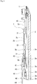
FIG. 1 is a schematic diagram illustrating a state in which a select jack and a selector of a needle a flat knitting machine according toEmbodiment 1 are arranged in a needle groove. -
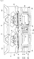
FIG. 2 is a schematic diagram illustrating part of central portion of a double-cam system included in the flat knitting machine according toEmbodiment 1. -
FIGS. 3 are schematic diagrams illustrating positional relationships between the select jack and the selector in the main portion shown inFIG. 2 . -
FIG. 4 is a schematic diagram illustrating part of an end portion of the double-cam system included in the flat knitting machine ofEmbodiment 1. -
FIGS. 5 are schematic diagrams illustrating positional relationships between a select jack and a selector of a flat knitting machine according toEmbodiment 2. -
FIGS. 6 are schematic diagrams illustrating positional relationships between a select jack and a selector of a flat knitting machine according toEmbodiment 3. -
FIG. 7 is a schematic diagram illustrating part of a cam system included in a flat knitting machine according toEmbodiment 4. -
FIG. 8 is a schematic diagram illustrating a state in which a needle is arranged in a needle groove formed in a needle bed of a conventional flat knitting machine. -
FIG. 9 is a schematic diagram illustrating a cam system of the conventional flat knitting machine. - Hereinafter, embodiments of the present invention will be described with reference to the drawings. The flat knitting machine of the present invention differs from the conventional flat knitting machine in a part of the needles and a part of the cam systems. The configurations having the same functions as those of the conventional flat knitting machines are denoted by the same reference signs as those in
FIGS. 8 and9 , and detailed description thereof is omitted. - The
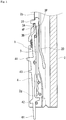
needle 1 arranged in theneedle groove 2g shown inFIG. 1 differs from the conventional needle in the configuration of aselect jack 3. Theselect jack 3 has a protrudingportion 3P that protrudes from the base portion of aselection butt 31 formed at the leading end of theselect jack 3 toward the back end of the needle 1 (lower side with respect to the paper plane). In theselect jack 3, an end surface of theselection butt 31 on the back end side of theneedle 1 functions as a first engagingportion 3A for engaging with aleading end portion 4F of theselector 4. The firstengaging portion 3A is a portion with which theleading end portion 4F of theselector 4 engages when theselector 4 moves from a bottom position to an intermediate position. As a result of the first engagingportion 3A being pushed up by theselector 4, theselect jack 3 moves from a B position to an H position. - Furthermore, in the
select jack 3 of this example, an end surface of the protrudingportion 3P on the back end side of theneedle 1 functions as a secondengaging portion 3B for engaging with theleading end portion 4F of theselector 4. In other words, the secondengaging portion 3B is located at a position that is closer to the back end side of theneedle 1 than the first engagingportion 3A is, and is shifted to the bottom side of theneedle groove 2g. The secondengaging portion 3B is a portion with which theleading end portion 4F of theselector 4 engages when theselector 4 moves from the bottom position to an advanced position. As a result of the secondengaging portion 3B being pushed up by theselector 4, theselect jack 3 moves from the H position to an A position. The distance between the first engagingportion 3A and the secondengaging portion 3B in the longitudinal direction of theneedle 1 is slightly smaller (by about 1 mm or smaller) than the distance from the bottom position to the intermediate position of theselector 4. Therefore, theselector 4 can move between the first engagingportion 3A and the secondengaging portion 3B smoothly. - On the other hand, the
selector 4 of this example has the same configuration as that of theconventional selector 40 shown inFIG. 8 . - The following will describe the
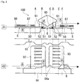
cam system 100 of this example with reference toFIG. 2. FIG. 2 shows only the portion of thecam system 100 that is involved in needle selection. Furthermore,FIG. 2 is used to describe an example in which theselect jack 3 moves to the H position due to first-stage needle selection, and moves to the A position due to second-stage needle selection.FIG. 2 only shows the routes of theselection butt 31 and the raisingbutt 42 in this example. The configurations of a fixing pressor 5 and aselector raising cam 8 of thecam system 100 of this example are different from those of the conventional flat knitting machine. Furthermore, thecam system 100 of this example includes aswitching cam 6 that is not provided in the conventional flat knitting machine. - The switching
cam 6 is provided along the lower-side edge portion of a selectjack lowering cam 82. In this example, the switchingcam 6 is separated from the selectjack lowering cam 82, but may be formed as one piece therewith. The switchingcam 6 is provided with abody portion 60 that is parallel to a cam plate 101 (seeFIG. 9 ), andslope portions 61 formed at both ends of thebody portion 60. The height, in the protruding direction (forward direction with respect to the paper plane), of thebody portion 60 of theswitching cam 6 is uniform, and is smaller than the height, in the protruding direction, of the fixing pressor 5. Theslope portions 61 have a surface that is gradually inclined upward from thecam plate 101 toward thebody portion 60. The width of thebody portion 60 is set to be equal to that of an area in which two raisingportions 84a are formed, or slightly larger or smaller than this area. With this configuration, thebody portion 60 can act on theselection butt 31 such that theleading end portion 4F of theselector 4 that is raised by the raisingportions 84a does not engage with the secondengaging portion 3B. The area in which the raisingportions 84a are formed refers to the distance area between the position at which the raisingbutt 42 comes into contact with theleft raising portion 84a, and the position at which the raisingbutt 42 comes into contact with theright raising portion 84a when the carriage moves in the direction opposite to that in this example. - This
switching cam 6 is configured to sink theselection butt 31 of the select jack 3 (FIG. 1 ) pushed up by theselector 4 and moved to the H position into theneedle groove 2g. With theswitching cam 6, theselection butt 31 is sunk into theneedle groove 2g to the extent such that part of theselection butt 31 protrudes from theneedle groove 2g. As a result, the switchingcam 6 separates theselect jack 3 and theselector 4 from each other in the depth direction of theneedle groove 2g. Details thereof will be described later with reference toFIG. 3 . - The fixing pressor 5 includes
intermediate portions 50 that are parallel to thecam plate 101, andcoupling portions 51 formed at both ends, in the extending direction, of theintermediate portions 50. Thecoupling portions 51 are shorter in height than theintermediate portions 50. The height, in the protruding direction, of thecoupling portions 51 conforms to the height, in the protruding direction, of the switching cam 6 (body portion 60). Eachintermediate portion 50 is coupled to thecoupling portions 51 byinclined portions 52 that each have a slope surface (indicated by "x" in the figure) inclined downward from theintermediate portion 50 toward the correspondingcoupling portion 51. Thecoupling portions 51 and theinclined portions 52 may also be separated from the fixing pressor 5. It is sufficient that the height, in the protruding direction, of thecoupling portions 51 conforms to the height, in the protruding direction, of theswitching cam 6 such that theselection butt 31 can smoothly move without interfering with the boundary between the fixing pressor 5 and theswitching cam 6. For example, the difference in the height in the protruding direction between thecoupling portions 51 and theswitching cam 6 is preferably 1 mm or smaller (including 0 mm). - The height, in the gap direction (upper direction with respect to the paper plane), of the
selector raising cam 8 is smaller than that of the conventionalselector raising cam 88 shown inFIG. 9 . This is the effect obtained by theselect jack 3 shown inFIG. 1 including the first engagingportion 3A and the secondengaging portion 3B. With a small height in the gap direction of theselector raising cam 8, the knitting cam 80 (FIG. 9 ) can be provided closer to the selectjack lowering cam 82. This can realize a reduction in the length, in the moving direction, of thecam system 100, and a reduction in the reciprocating stroke of the carriage. Also, with a reduced length in the moving direction of the carriage, the weight of the carriage can be reduced, which increases the moving speed of the carriage. As a result, the knitting time is reduced, and the knitting efficiency is improved. - Here, the height, in the gap direction, of the
selector raising cam 8 can be set to be, for example, 1 to 1.6 times inclusive as large as the height, in the gap direction, of the raisingportions 84a of the lowerselector guiding cam 84. The height, in the gap direction, of the selector raising cam 8 (raisingportions 84a) refers to the distance from a reference position to the top of the selector raising cam 8 (raisingportions 84a), the reference position being the position at which the raisingbutt 42 at the bottom position first comes into contact. In contrast, it is not possible to set the height, in the gap direction, of the conventionalselector raising cam 88 shown inFIG. 9 to be 1.6 times or less as large as the height in the gap direction of the raisingportion 84a. - The following will describe, with reference to
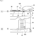
FIGS. 3 , the positional relationship between theselect jack 3 and theselector 4 when theselect jack 3 moves to the H position due to the first-stage needle selection, and to the A position due to the second-stage needle selection.FIGS. 3(A) to 3(F) respectively correspond to the vertical dashed lines denoted by capital letters A to F shown inFIG. 2 . - In
FIG. 3(A) , theselect jack 3 is at the B position, and theselection butt 31 of theselect jack 3 is sunk into theneedle groove 2g by theintermediate portion 50 of the fixing pressor 5. On the other hand, theselector 4 is at the bottom position, and theleading end portion 4F of theselector 4 is not pushing up theselection butt 31. - In
FIG. 3(B) , theselection butt 31 abuts against theinclined portion 52 of the fixing pressor 5, and is slightly raised from theneedle groove 2g relative to the state shown inFIG. 3(A) . Thebody portion 60 of theswitching cam 6 is present on the gap side (upper side with respect to the paper plane) of theinclined portion 52. - In
FIG. 3(C) , as a result of theselector 4 moving to the intermediate position, theleading end portion 4F of theselector 4 pushes up the first engagingportion 3A of theselect jack 3, and theselect jack 3 is moved to the H position and is arranged on thebody portion 60 of theswitching cam 6. Theselection butt 31 of theselect jack 3 is pushed by the switchingcam 6 so that almost half of theselection butt 31 is sunk in theneedle groove 2g. Accordingly, theselect jack 3 and theselector 4 are separated from each other in the depth direction (left-right direction with respect to the paper plane) of theneedle groove 2g. - In
FIG. 3(D) , theselector 4 is once returned to the bottom position. At this time, since theselect jack 3 and theselector 4 are separated from each other in the depth direction of theneedle groove 2g, theselector 4 is not likely to interfere with theselect jack 3 when moving. Accordingly, theselect jack 3 does not move in an unintended manner, and theselect jack 3 remains at the H position. In the zones betweenFIGS. 3(B) to 3(D) , that is, the zone in which theselect jack 3 moves to the H position due to the first-stage needle selection, theselection butt 31 moves while being sunk by thebody portion 60. - In
FIG. 3(E) , theselection butt 31 has passed by the switchingcam 6, and is raised from theneedle groove 2g. Therefore, the portion of theselect jack 3 on its leading end side and theselector 4 come close to each other in the depth direction of theneedle groove 2g so that theleading end portion 4F of theselector 4 faces and is close to the secondengaging portion 3B of theselect jack 3. - In
FIG. 3(F) , as a result of theselector 4 moving to the advanced position, theleading end portion 4F of theselector 4 pushes up the secondengaging portion 3B, and theselect jack 3 is moved to the A position. Here, as shown inFIG. 3(E) , at a point in time at which theselector 4 is at the bottom position, theleading end portion 4F of theselector 4 is already close to the secondengaging portion 3B of theselect jack 3 at the H position. Accordingly, inFIG. 3(F) , the distance for which theselector 4 idles is significantly reduced, and the distance for which theselector 4 is moved from the bottom position to the advanced position is also reduced. - The following will describe a configuration of a
switching cam 6 that corresponds to theneedle selection actuator 94 located at an end of the carriage, with reference toFIG. 4 . At the end of the carriage, when the carriage moves leftward with respect to the paper plane, the first-stage needle selection is performed by theneedle selection actuator 94. Then, when the carriage is returned and moved rightward with respect to the paper plane, the second-stage needle selection is performed by theneedle selection actuator 94. When the carriage is returned after the first-stage needle selection, the selector is lowered to the bottom position by the upperselector guiding cam 83, is raised to the intermediate position by the raisingportion 84a on the left side of the paper plane, and then is subjected to the second-stage needle selection.FIG. 4 only shows the routes of theselection butt 31 and the raisingbutt 42 during the first-stage needle selection. - At the end of the carriage shown in
FIG. 4 , the switchingcam 6 is also provided along the edge portion of the selectjack lowering cam 82. Also with thisswitching cam 6, shifting of engagement between theselect jack 3 and theselector 4 as described with reference toFIG. 3 can also be performed, and thus the height, in the gap direction, of theselector raising cam 8 can be reduced relative to that in the conventional configuration. - Note however that, at the end of the carriage, the
selector 4 subjected to the first-stage needle selection remains at the intermediate position. Theselector 4 at the intermediate position is supported by thewires 2w, as shown inFIG. 3(C) , for example. Therefore, even if, after completion of the first-stage needle selection, an operator stops the carriage for maintenance and touches theselector 4, theselector 4 will not be sunk into theneedle groove 2g. Accordingly, even if the running of the carriage is restarted after the maintenance, no trouble will occur in the second-stage needle selection. - Here, in contrast to
FIGS. 2 and4 , there are also cases where the first-stage needle selection is performed in a state in which theselection butt 31 is at the H position or the A position. In this case, theselection butt 31 runs over thebody portion 60 via theslope portion 61. Then, theselection butt 31 is lowered by the selectjack lowering cam 82 to the B position. At this time, thebody portion 60 of theswitching cam 6 sinks theselection butt 31, and the secondengaging portion 3B and theleading end portion 4F are shifted from each other in the depth direction of theneedle groove 2g. This can prevent the secondengaging portion 3B from colliding and engaging with theleading end portion 4F of theselector 4 when theselect jack 3 is lowered to the B position. -
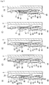
Embodiment 2 will describe an example in which the shapes of theselect jack 3 and theselector 4 are different from those ofEmbodiment 1, with reference toFIGS. 5. FIGS. 5(B) to 5(F) respectively correspond to the vertical dashed lines denoted by capital letters B to F shown inFIG. 2 . - As shown in
FIG. 5(B) , in theselect jack 3 of this example, one of the bifurcated back ends that is located on the opening side of theneedle groove 2g serves as a first engagingportion 3A. Furthermore, in theselect jack 3 of this example, the end surface of the protrudingportion 3P on the back end side of theneedle 1 serves as a secondengaging portion 3B, similar toEmbodiment 1. - In
FIG. 5(C) , theselector 4 is moved to the intermediate position. At this time, the first engagingportion 3A of theselect jack 3 is pushed up by an engagingprojection 45 of theselector 4 that projects to the side (bottom side of theneedle groove 2g) opposite to the raisingbutt 42. As a result, theselect jack 3 is also moved to the H position. Theselection butt 31 of theselect jack 3 is arranged on theswitching cam 6. - In
FIG. 5(D) , theselector 4 returns to the bottom position. InFIG. 5(E) , theselection butt 31 is moved to a position at which theswitching cam 6 is not present (see the vertical dashed line E inFIG. 2 ), and thus theselection butt 31 is raised from theneedle groove 2g. As a result, theleading end portion 4F of theselector 4 engages with the secondengaging portion 3B. The firstengaging portion 3A is separated from the engagingprojection 45. - In
FIG. 5(F) , theselector 4 is moved from the bottom position to the advanced position, and theselect jack 3 pushed up by theleading end portion 4F is also moved to the A position. Referring toFIGS. 5(E) and 5(F) , it is clear that, also with the configuration of this example, there is hardly any idle distance for which theselector 4 idles. -
Embodiment 3 will describe an example in which the shapes of theselect jack 3 and theselector 4 are different from those ofEmbodiments FIGS. 6. FIGS. 6(B) to 6(F) respectively correspond to the vertical dashed lines denoted by capital letters B to F shown inFIG. 2 . - As shown in
FIG. 6(B) , similar toEmbodiment 1, in theselect jack 3 of this example, the end surface of theselection butt 31 on the back end side of theneedle 1 serves as the first engagingportion 3A. Furthermore, in theselect jack 3 of this example, the protruding second engagingportion 3B is formed at a position in an intermediate part of theselect jack 3 that is only slightly on the A position side. The secondengaging portion 3B protrudes to theselector 4 side (opening side of theneedle groove 2g). On the other hand, theselector 4 has an engagingprojection 4p at a position in an intermediate part of theselector 4 that is only slightly on the advanced position side. When theselect jack 3 is at the B position and theselector 4 is at the bottom position, the engagingprojection 4p is arranged on the A position side of the secondengaging portion 3B. The engagingprojection 4p and the secondengaging portion 3B are separated from each other in the depth direction of theneedle groove 2g. - In
FIG. 6(C) , theselector 4 is moved to the intermediate position. At this time, the first engagingportion 3A of theselect jack 3 is pushed up by theleading end portion 4F of theselector 4. As a result, theselect jack 3 is also moved to the H position. Theselection butt 31 of theselect jack 3 is arranged on theswitching cam 6. - In
FIG. 6(D) , theselector 4 returns to the bottom position. As a result of theselector 4 returning to the bottom position, the positions, in the gap direction, of the engagingprojection 4p and the secondengaging portion 3B are replaced by each other, and the engagingprojection 4p is arranged further on the back side of theneedle 1 than the secondengaging portion 3B. At this time, since theselection butt 31 is pushed by the switchingcam 6, and the separation distance between theselect jack 3 and theselector 4 is kept as is, the engagingprojection 4p and the secondengaging portion 3B are prevented from interfering with each other. - In
FIG. 6(E) , theselection butt 31 is disengaged from the switchingcam 6, and theselection butt 31 is raised from theneedle groove 2g. At this time, the engagingprojection 4p and the secondengaging portion 3B are arranged at positions at which they can engage with each other in the depth direction of theneedle groove 2g. Accordingly, the engagingprojection 4p of theselector 4 engages with the secondengaging portion 3B. The firstengaging portion 3A is separated from theleading end portion 4F. - In
FIG. 6(F) , theselector 4 is moved from the bottom position to the advanced position, and theselect jack 3 pushed up by the engagingprojection 4p is moved to the A position. Referring toFIGS. 6(E) and 6(F) , it is clear that, also with the configuration of this example, there is hardly any idle distance for which theselector 4 idles. -
Embodiment 4 will describe an example in which the shapes of the upperselector guiding cam 83, the lowerselector guiding cam 84, and the selectjack lowering cam 82 are different from those ofEmbodiment 1, with reference toFIG. 7 . The functions of thecams Embodiment 1. - The lower
selector guiding cam 84 of this example includes only one raisingportion 84a. Conforming to this shape of the lowerselector guiding cam 84, the upperselector guiding cam 83 is shaped so as to be able to return the loweringbutt 41 to the B position. - On the other hand, the select
jack lowering cam 82 is shaped such that an intermediate part thereof is recessed in the gap direction (upper direction with respect to the paper plane). Both end portions of the recessed portion respectively have slope surfaces that are raised in the protruding direction (forward direction with respect to the paper plane) from the intermediate part toward the two ends. The width of the recessed portion excluding the slope surfaces is set to be equal to that of an area in which the raisingportion 84a is formed, or slightly larger or smaller than this area, so that theselection butt 31 moving from the B position to the H position does not interfere with the slope surfaces. Therefore, theselection butt 31 at the H position can pass by the selectjack lowering cam 82 while remaining at the H position. - The above-described configuration may also employ the
switching cam 6 described inEmbodiment 1. Similar toEmbodiment 1, the switchingcam 6 is arranged along the edge portion of the selectjack lowering cam 82, and contributes to shifting of the engagement position between theselect jack 3 and theselector 4. - Although,
Embodiments 1 to 4 have described examples in which the mechanicalneedle selection actuators needle selection actuators JP 3459514B
Claims (3)
- A flat knitting machine comprising:at least a front and a back needle bed (2);a plurality of needles (1) respectively arranged in a plurality of needle grooves (2g) formed in the needle beds (2);a cam system (100) configured to move the needles (1) forward and backward in a direction along the needle grooves (2g), so that the needles (1) perform a knitting operation; andneedle selection actuators (91, 92, 93, 94) configured to perform needle selection on the needles (1),each of the needles (1) including:a select jack (3) having a selection butt (31) that is subjected to the action of the cam system (100), the select jack (3) being configured to cause the needle (1) to perform different knitting operations; anda selector (4) configured to change the position of the select jack (3) along the needle groove (2g),the select jack (3) being configured to move to any of a B position, an H position, and an A position, based on a result of the needle selection performed by the needle selection actuators (91, 92, 93, 94),the selector (4) being configured to move to any of a bottom position that corresponds to the B position, an intermediate position that corresponds to the H position, and an advanced position that corresponds to the A position,the cam system (100) including:a fixing pressor (5) configured to sink the selection butt (31) at the B position into the needle groove (2g); anda select jack lowering cam (82) configured to bring the selection butt (31) at the H position or the A position to the B position,wherein the select jack (3) includes:a first engaging portion (3A) with which part of the selector (4) engages when the selector (4) moves from the bottom position to the intermediate position; anda second engaging portion (3B) with which part of the selector (4) engages when the selector (4) moves from the bottom position to the advanced position,the cam system (100) includes
a switching cam (6) that is provided along an edge portion of the select jack lowering cam (82), and is configured to sink the selection butt (31) into the needle groove (2g) when switching the selector (4) from engaging with the first engaging portion (3A) to engaging with the second engaging portion (3B), andthe switching cam (6) has a height in a protruding direction that is smaller than the height, in a protruding direction, of the fixing pressor (5). - The flat knitting machine according to claim 1,
wherein the select jack (3) includes a protruding portion (3P) that protrudes to a back end side of the needle (1) from a base portion, on the back end side, of the selection butt (31),
the first engaging portion (3A) is constituted by an end surface, on the back end side, of the selection butt (31), and
the second engaging portion (3B) is constituted by an end surface, on the back end side, of the protruding portion (3P). - The flat knitting machine according to claim 1 or 2, further comprising
a coupling portion (51) provided at an end, in an extending direction, of the fixing pressor (5), and is configured to come close to the switching cam (6),
wherein a height, in a protruding direction, of the coupling portion (51) conforms to the height, in the protruding direction, of the switching cam (6).
Applications Claiming Priority (1)
| Application Number | Priority Date | Filing Date | Title |
|---|---|---|---|
| JP2019073176A JP7307580B2 (en) | 2019-04-05 | 2019-04-05 | flat knitting machine |
Publications (2)
| Publication Number | Publication Date |
|---|---|
| EP3719191A1 true EP3719191A1 (en) | 2020-10-07 |
| EP3719191B1 EP3719191B1 (en) | 2023-12-06 |
Family
ID=70165896
Family Applications (1)
| Application Number | Title | Priority Date | Filing Date |
|---|---|---|---|
| EP20167838.0A Active EP3719191B1 (en) | 2019-04-05 | 2020-04-02 | Flat knitting machine |
Country Status (4)
| Country | Link |
|---|---|
| EP (1) | EP3719191B1 (en) |
| JP (1) | JP7307580B2 (en) |
| KR (1) | KR102366041B1 (en) |
| CN (1) | CN111793889B (en) |
Cited By (1)
| Publication number | Priority date | Publication date | Assignee | Title |
|---|---|---|---|---|
| EP4253625A1 (en) * | 2022-04-01 | 2023-10-04 | Shima Seiki Mfg., Ltd. | Flatbed knitting machine and its needle selection mechanism |
Citations (3)
| Publication number | Priority date | Publication date | Assignee | Title |
|---|---|---|---|---|
| JPH06200455A (en) * | 1992-12-26 | 1994-07-19 | Shima Seiki Mfg Ltd | Needle selector of flat knitting machine |
| JP3459514B2 (en) | 1995-06-15 | 2003-10-20 | 株式会社島精機製作所 | Needle selection device in flat knitting machine |
| WO2007074944A1 (en) | 2005-12-27 | 2007-07-05 | Shima Seiki Mfg., Ltd. | Needle selecting device for weft knitting machine |
Family Cites Families (6)
| Publication number | Priority date | Publication date | Assignee | Title |
|---|---|---|---|---|
| US7213422B2 (en) * | 2002-06-26 | 2007-05-08 | Shima Seiki Manufacturing Limited | Needle selection device for weft knitting machine |
| CN101314888B (en) * | 2008-07-16 | 2011-04-06 | 冯加林 | Triangular knitting control system employing electromagnetic needle selection |
| CN201268764Y (en) * | 2008-09-11 | 2009-07-08 | 钱福海 | Three-system computer flat knitting machine |
| JP5286249B2 (en) * | 2009-12-29 | 2013-09-11 | 株式会社島精機製作所 | Deshan cam device |
| JP5844586B2 (en) * | 2011-09-16 | 2016-01-20 | 株式会社島精機製作所 | Needle selection system of flat knitting machine, selector, and flat knitting machine |
| CN104328594B (en) * | 2014-11-24 | 2016-07-27 | 西安工程大学 | Adopt five merit position Computerized flat knitting machine knitting mechanisms of electromagnetic needle selection |
-
2019
- 2019-04-05 JP JP2019073176A patent/JP7307580B2/en active Active
-
2020
- 2020-04-02 EP EP20167838.0A patent/EP3719191B1/en active Active
- 2020-04-02 KR KR1020200040256A patent/KR102366041B1/en active IP Right Grant
- 2020-04-02 CN CN202010254838.9A patent/CN111793889B/en active Active
Patent Citations (4)
| Publication number | Priority date | Publication date | Assignee | Title |
|---|---|---|---|---|
| JPH06200455A (en) * | 1992-12-26 | 1994-07-19 | Shima Seiki Mfg Ltd | Needle selector of flat knitting machine |
| JP3459514B2 (en) | 1995-06-15 | 2003-10-20 | 株式会社島精機製作所 | Needle selection device in flat knitting machine |
| WO2007074944A1 (en) | 2005-12-27 | 2007-07-05 | Shima Seiki Mfg., Ltd. | Needle selecting device for weft knitting machine |
| EP1975295A1 (en) * | 2005-12-27 | 2008-10-01 | Shima Seiki Manufacturing., Ltd. | Needle selecting device for weft knitting machine |
Cited By (1)
| Publication number | Priority date | Publication date | Assignee | Title |
|---|---|---|---|---|
| EP4253625A1 (en) * | 2022-04-01 | 2023-10-04 | Shima Seiki Mfg., Ltd. | Flatbed knitting machine and its needle selection mechanism |
Also Published As
| Publication number | Publication date |
|---|---|
| JP7307580B2 (en) | 2023-07-12 |
| KR102366041B1 (en) | 2022-02-21 |
| CN111793889B (en) | 2022-01-07 |
| KR20200117891A (en) | 2020-10-14 |
| EP3719191B1 (en) | 2023-12-06 |
| JP2020169431A (en) | 2020-10-15 |
| CN111793889A (en) | 2020-10-20 |
Similar Documents
| Publication | Publication Date | Title |
|---|---|---|
| EP2196569B1 (en) | Weft knitting machine | |
| US5398527A (en) | Flat knitting machine having a transferring mechanism | |
| EP2894245B1 (en) | Flatbed knitting machine equipped with sinker device | |
| JP2007231447A (en) | Knitting cam device of flat knitting machine | |
| EP2942428B1 (en) | Method for split-knitting | |
| US20070289338A1 (en) | Complex Cam System | |
| EP3719191A1 (en) | Flat knitting machine | |
| EP2471984B1 (en) | Flat knitting machine | |
| EP2397589B1 (en) | Compound needle for flatbed knitting machine | |
| EP3608461B1 (en) | Plating knitting method used in flat knitting machine | |
| JP5844586B2 (en) | Needle selection system of flat knitting machine, selector, and flat knitting machine | |
| EP3978669B1 (en) | Flatbed knitting machine | |
| EP2570535B1 (en) | Flatbed knitting machine provided with compound needle, and slider control method for flatbed knitting machine | |
| JP5632277B2 (en) | Compound needle of flat knitting machine | |
| US20030159473A1 (en) | Weft knitting machine with transfer mechanism and transferring method | |
| JP2012082531A (en) | Needle selector | |
| JP5414674B2 (en) | Knitting needle driving cam and flat knitting machine | |
| EP4253625A1 (en) | Flatbed knitting machine and its needle selection mechanism | |
| CN216514444U (en) | Needle selector of circular knitting machine | |
| US6668595B2 (en) | Weft knitting machine with transfer mechanism | |
| CN115142183A (en) | Needle selection device and method of flat knitting machine |
Legal Events
| Date | Code | Title | Description |
|---|---|---|---|
| PUAI | Public reference made under article 153(3) epc to a published international application that has entered the european phase |
Free format text: ORIGINAL CODE: 0009012 |
|
| STAA | Information on the status of an ep patent application or granted ep patent |
Free format text: STATUS: THE APPLICATION HAS BEEN PUBLISHED |
|
| AK | Designated contracting states |
Kind code of ref document: A1 Designated state(s): AL AT BE BG CH CY CZ DE DK EE ES FI FR GB GR HR HU IE IS IT LI LT LU LV MC MK MT NL NO PL PT RO RS SE SI SK SM TR |
|
| AX | Request for extension of the european patent |
Extension state: BA ME |
|
| STAA | Information on the status of an ep patent application or granted ep patent |
Free format text: STATUS: REQUEST FOR EXAMINATION WAS MADE |
|
| 17P | Request for examination filed |
Effective date: 20210407 |
|
| RBV | Designated contracting states (corrected) |
Designated state(s): AL AT BE BG CH CY CZ DE DK EE ES FI FR GB GR HR HU IE IS IT LI LT LU LV MC MK MT NL NO PL PT RO RS SE SI SK SM TR |
|
| STAA | Information on the status of an ep patent application or granted ep patent |
Free format text: STATUS: EXAMINATION IS IN PROGRESS |
|
| 17Q | First examination report despatched |
Effective date: 20220323 |
|
| GRAP | Despatch of communication of intention to grant a patent |
Free format text: ORIGINAL CODE: EPIDOSNIGR1 |
|
| STAA | Information on the status of an ep patent application or granted ep patent |
Free format text: STATUS: GRANT OF PATENT IS INTENDED |
|
| INTG | Intention to grant announced |
Effective date: 20230629 |
|
| GRAS | Grant fee paid |
Free format text: ORIGINAL CODE: EPIDOSNIGR3 |
|
| GRAA | (expected) grant |
Free format text: ORIGINAL CODE: 0009210 |
|
| STAA | Information on the status of an ep patent application or granted ep patent |
Free format text: STATUS: THE PATENT HAS BEEN GRANTED |
|
| AK | Designated contracting states |
Kind code of ref document: B1 Designated state(s): AL AT BE BG CH CY CZ DE DK EE ES FI FR GB GR HR HU IE IS IT LI LT LU LV MC MK MT NL NO PL PT RO RS SE SI SK SM TR |
|
| REG | Reference to a national code |
Ref country code: GB Ref legal event code: FG4D |
|
| REG | Reference to a national code |
Ref country code: CH Ref legal event code: EP |
|
| REG | Reference to a national code |
Ref country code: DE Ref legal event code: R096 Ref document number: 602020022167 Country of ref document: DE |
|
| REG | Reference to a national code |
Ref country code: IE Ref legal event code: FG4D |
|
| REG | Reference to a national code |
Ref country code: LT Ref legal event code: MG9D |
|
| PG25 | Lapsed in a contracting state [announced via postgrant information from national office to epo] |
Ref country code: GR Free format text: LAPSE BECAUSE OF FAILURE TO SUBMIT A TRANSLATION OF THE DESCRIPTION OR TO PAY THE FEE WITHIN THE PRESCRIBED TIME-LIMIT Effective date: 20240307 |
|
| REG | Reference to a national code |
Ref country code: NL Ref legal event code: MP Effective date: 20231206 |
|
| PG25 | Lapsed in a contracting state [announced via postgrant information from national office to epo] |
Ref country code: LT Free format text: LAPSE BECAUSE OF FAILURE TO SUBMIT A TRANSLATION OF THE DESCRIPTION OR TO PAY THE FEE WITHIN THE PRESCRIBED TIME-LIMIT Effective date: 20231206 |
|
| PG25 | Lapsed in a contracting state [announced via postgrant information from national office to epo] |
Ref country code: ES Free format text: LAPSE BECAUSE OF FAILURE TO SUBMIT A TRANSLATION OF THE DESCRIPTION OR TO PAY THE FEE WITHIN THE PRESCRIBED TIME-LIMIT Effective date: 20231206 |
|
| PG25 | Lapsed in a contracting state [announced via postgrant information from national office to epo] |
Ref country code: LT Free format text: LAPSE BECAUSE OF FAILURE TO SUBMIT A TRANSLATION OF THE DESCRIPTION OR TO PAY THE FEE WITHIN THE PRESCRIBED TIME-LIMIT Effective date: 20231206 Ref country code: GR Free format text: LAPSE BECAUSE OF FAILURE TO SUBMIT A TRANSLATION OF THE DESCRIPTION OR TO PAY THE FEE WITHIN THE PRESCRIBED TIME-LIMIT Effective date: 20240307 Ref country code: ES Free format text: LAPSE BECAUSE OF FAILURE TO SUBMIT A TRANSLATION OF THE DESCRIPTION OR TO PAY THE FEE WITHIN THE PRESCRIBED TIME-LIMIT Effective date: 20231206 Ref country code: BG Free format text: LAPSE BECAUSE OF FAILURE TO SUBMIT A TRANSLATION OF THE DESCRIPTION OR TO PAY THE FEE WITHIN THE PRESCRIBED TIME-LIMIT Effective date: 20240306 |
|
| REG | Reference to a national code |
Ref country code: AT Ref legal event code: MK05 Ref document number: 1638493 Country of ref document: AT Kind code of ref document: T Effective date: 20231206 |
|
| PG25 | Lapsed in a contracting state [announced via postgrant information from national office to epo] |
Ref country code: NL Free format text: LAPSE BECAUSE OF FAILURE TO SUBMIT A TRANSLATION OF THE DESCRIPTION OR TO PAY THE FEE WITHIN THE PRESCRIBED TIME-LIMIT Effective date: 20231206 |