EP2471984B1 - Flat knitting machine - Google Patents
Flat knitting machine Download PDFInfo
- Publication number
- EP2471984B1 EP2471984B1 EP11010256.3A EP11010256A EP2471984B1 EP 2471984 B1 EP2471984 B1 EP 2471984B1 EP 11010256 A EP11010256 A EP 11010256A EP 2471984 B1 EP2471984 B1 EP 2471984B1
- Authority
- EP
- European Patent Office
- Prior art keywords
- butt
- needle
- presser
- raising
- knitting
- Prior art date
- Legal status (The legal status is an assumption and is not a legal conclusion. Google has not performed a legal analysis and makes no representation as to the accuracy of the status listed.)
- Active
Links
- 238000009940 knitting Methods 0.000 title claims description 133
- 230000007246 mechanism Effects 0.000 claims description 8
- 230000007704 transition Effects 0.000 claims description 5
- 230000009471 action Effects 0.000 claims description 2
- 239000004744 fabric Substances 0.000 claims description 2
- 238000010586 diagram Methods 0.000 description 3
- 238000012552 review Methods 0.000 description 3
- 230000008859 change Effects 0.000 description 1
- 230000002708 enhancing effect Effects 0.000 description 1
- 238000000034 method Methods 0.000 description 1
- 230000008569 process Effects 0.000 description 1
- 230000004044 response Effects 0.000 description 1
Images


Classifications
-
- D—TEXTILES; PAPER
- D04—BRAIDING; LACE-MAKING; KNITTING; TRIMMINGS; NON-WOVEN FABRICS
- D04B—KNITTING
- D04B15/00—Details of, or auxiliary devices incorporated in, weft knitting machines, restricted to machines of this kind
- D04B15/32—Cam systems or assemblies for operating knitting instruments
- D04B15/36—Cam systems or assemblies for operating knitting instruments for flat-bed knitting machines
- D04B15/362—Cam systems or assemblies for operating knitting instruments for flat-bed knitting machines with two needle beds in V-formation
- D04B15/365—Cam systems or assemblies for operating knitting instruments for flat-bed knitting machines with two needle beds in V-formation with provision for loop transfer from one needle bed to the other
-
- D—TEXTILES; PAPER
- D04—BRAIDING; LACE-MAKING; KNITTING; TRIMMINGS; NON-WOVEN FABRICS
- D04B—KNITTING
- D04B7/00—Flat-bed knitting machines with independently-movable needles
-
- D—TEXTILES; PAPER
- D04—BRAIDING; LACE-MAKING; KNITTING; TRIMMINGS; NON-WOVEN FABRICS
- D04B—KNITTING
- D04B15/00—Details of, or auxiliary devices incorporated in, weft knitting machines, restricted to machines of this kind
- D04B15/28—Needle pressers
-
- D—TEXTILES; PAPER
- D04—BRAIDING; LACE-MAKING; KNITTING; TRIMMINGS; NON-WOVEN FABRICS
- D04B—KNITTING
- D04B15/00—Details of, or auxiliary devices incorporated in, weft knitting machines, restricted to machines of this kind
- D04B15/32—Cam systems or assemblies for operating knitting instruments
- D04B15/36—Cam systems or assemblies for operating knitting instruments for flat-bed knitting machines
-
- D—TEXTILES; PAPER
- D04—BRAIDING; LACE-MAKING; KNITTING; TRIMMINGS; NON-WOVEN FABRICS
- D04B—KNITTING
- D04B15/00—Details of, or auxiliary devices incorporated in, weft knitting machines, restricted to machines of this kind
- D04B15/66—Devices for determining or controlling patterns ; Programme-control arrangements
- D04B15/68—Devices for determining or controlling patterns ; Programme-control arrangements characterised by the knitting instruments used
- D04B15/70—Devices for determining or controlling patterns ; Programme-control arrangements characterised by the knitting instruments used in flat-bed knitting machines
Definitions
- the present invention relates to a flat knitting machine excelling in knitting efficiency than the related art.
- a flat knitting machine includes at least a pair of front and back needle beds, a knitting needle arranged in each of a large number of needle grooves arranged side by side in each needle bed, and a carriage that reciprocates along a longitudinal direction of the needle beds (refer to Patent Documents 1 and 2, for example).
- a cam system is mounted on the carriage, which cam system causes the knitting needles to perform knitting operations (knit, tuck, miss, and transfer of stitches between the front and back needle beds).
- FIG. 5 is a schematic explanatory view showing a corresponding state of a knitting needle 100 and a cam system 200. Only part of the cam system 200 is shown in Fig. 5 for the sake of convenience of the explanation. In the figure, a travel path formed on the cam system 200 by some of butts arranged on the knitting needle when transferring the stitches is shown.
- the knitting needle 100 of the flat knitting machine shown in Patent Documents 1, 2 includes a needle main body 1 with a hook, a needle jack 2 for advancing and retreating the needle main body 1 in a longitudinal direction of the needle groove, a select jack 3 for controlling whether or not to advance or retreat the needle jack 2, and a selector 4 for changing the position of the select jack 3 in the longitudinal direction of the needle groove.
- the knitting needle 100 In response to the needle selection of two stages by a needle selection actuator 99 of an oscillating type or a direct acting type, the knitting needle 100 carries out the knitting operation corresponding to the result of the needle selection and the state of the cam system 200.
- the needle selection of the knitting needle 100 is carried out by changing the position of the select jack 3 in the longitudinal direction of the needle groove by means of the selector 4 in which the needle is selected by the needle selection actuator 99.
- the needle jack 2 for moving the needle main body 1 along the needle groove according to the position of the select jack 3 includes a knitting butt 21 and a transferring butt 22.
- the cam system 200 acts on the butts 21, 22, the needle jack 2 advances or retreats along the needle groove thus carrying out the knitting operation.
- the operation of receiving the stitch from the opposing knitting needle and the operation of transferring the stitch to the opposing knitting needle will be representatively described.
- the select jack 3 When carrying out the receiving operation of the stitch, the select jack 3 is at the H position (first position) after the needle selection of the first stage, where a movable needle raising cam 83 of the cam system 200 is in an in-state, transfer cams 88, 89 are in an out-state (the cam 89 is always in the out-state and will not be in the in-state), half pressers (selection pressers) 91, 92 are arranged on a travel path of a selecting butt 31 formed at a distal end of the select jack 3, and a tuck presser 90 is retracted from the travel path.
- the selecting butt 31 is sunk into the needle groove by the half presser 91 of the cam system 200, so that the distal end of the select jack 3 curves the intermediate portion of the needle jack 2 and sinks the knitting butt 21 of the needle jack 2 into the needle groove.
- a fixed needle raising cam 80 does not act on the knitting butt 21 of the needle jack 2, and the needle jack 2 does not move along the needle groove.
- the select jack 3 When carrying out the transferring operation of the stitch, the select jack 3 is at the A position (second position) by the needle selection of the second stage after being at the H position by the needle selection of the first stage, where the movable needle raising cam 83 is in the in-state, and the transfer cams 88, 89 are in the out-state.
- the half pressers 91, 92 and the tuck presser 90 do not overlap with the travel path of the A position even when retracted from the travel path of the H position, and thus the arrangement of the pressers 90, 91, 92 is not an issue.
- the selecting butt 31 is not sunk into the needle groove even once, and the butts 21, 22 draw the travel path along the cam system 200 so that the transferring operation of the stitch is carried out, as shown in the figure.
- the present inventor focused on the configuration of the half pressers after carrying out the following review.
- a plurality of knitting needles 100 reaching the H position after the needle selection of the first stage is sometimes sorted into the knitting needle 100 remaining at the H position and the knitting needle 100 changed from the H position to the A position in the needle selection of the second stage.
- the knitting needle 100 that transfers the stitch is at the A position and the knitting needle 100 that receives the stitch is at the H position.
- the selecting butt 31 needs to be pushed up to the A position where the half presser 91 does not act before the selecting butt 31 is sunk into the needle groove by the half presser 91 in order to raise the select jack 3 from the H position to the A position.
- the branched point BP where the selecting butt 31 transitions from the H position (first position) to the A position (second position) needs to be positioned on the outer side of the half presser 91 (side away from the center line of the cam system 200 shown with a chain dashed line in Fig. 5 ).
- a selector raising cam (raising butt raising cam) 87 for pushing up the raising butt 41 of the selector 4 to the needle bed gap side, and the position of the needle selection actuator 99 are also defined by the half presser 91.
- Fig. 5 shows the position (dotted line on right side) where the half presser 91 starts to act on the selecting butt 31, and the position (dotted line on left side) where the selector raising cam 87 for causing the select jack 3 to be in the A position starts to act on the raising butt 41.
- the half presser 91 on the preceding side sinks the selecting butt 31 in the needle groove far before the knitting butt 21 makes contact with the fixed needle raising cam 80. That is, the half presser 91 is longer than the length necessary as the half presser on the preceding side. This is because, when the knitting direction is interchanged and the half presser 91 becomes the half presser on the following side, the half presser 91 needs to have a length necessary as the half presser on the following side.
- the half presser 92 on the following side in the knitting is used to avoid the draw-in of the knitting needle 100 by the stitch cam 86, in which case, a length that the knitting butt 21 can reliably pass the stitch cam 86 becomes necessary. Therefore, the half presser 91 is designed such that a length the knitting butt 21 can reliably pass the stitch cam 85 is realized when the half presser 91 becomes the half presser on the following side.
- the present inventor again reviewed the configuration of the half presser based on the reviews described above, and completed the flat knitting machine of the present invention.
- the flat knitting machine of the present invention is as defined below.
- a flat knitting machine of the present invention includes at least a pair of front and back needle beds, a knitting needle arranged in each of a plurality of needle grooves arranged side by side in a longitudinal direction of each needle bed, and a cam system for causing the knitting needle to carry out a knitting operation by acting on a plurality of butts arranged on the knitting needle to advance and retreat the knitting needle in the longitudinal direction of the needle groove, the cam system reciprocating along the longitudinal direction of the needle bed when knitting a knitted fabric.
- the knitting needle of the flat knitting machine includes a knitting butt, a selecting butt, and a raising butt.
- the knitting butt advances and retreats the knitting needle when acted upon by the cam system.
- the selecting butt may sequentially take at least two positions, a first position and a second position, towards the needle bed gap side in the longitudinal direction of the knitting needle, and change the knitting operation to be carried out by the knitting needle according to the position.
- the raising butt changes the position of the selecting butt.
- the cam system of the flat knitting machine includes a needle raising cam, stitch cams arranged in a pair on the left and the right of the needle raising cam, a pair of left and right selection pressers, and a pair of left and right raising butt raising cams.
- the needle raising cam acts on the knitting butt to advance the knitting needle when the selecting butt is at the second position.
- the stitch cam retreats the knitting needle advanced by the action of the needle raising cam.
- the selection pressers may take two states, an acting state of projecting out on a travel path of the selecting butt to sink the selecting butt in the needle groove and a non-acting state of not projecting out on the travel path and not acting on the selecting butt when the selecting butt is at the first position.
- the raising butt raising cam pushes up the raising butt towards the needle bed gap to move the selecting butt from the first position to the second position.
- the selection pressers are formed to a length capable of sinking the selecting butt in the needle groove to sink the knitting butt in the needle groove so that the knitting butt does not act on the stitch cam when on the following side in the advancing direction of the cam system.
- the raising butt raising cam is positioned such that a branched point where the selecting butt transitions from the first position to the second position overlaps with the selection presser on the preceding side as the raising butt raising cam acts on the raising butt on the preceding side in the advancing direction.
- the flat knitting machine of the present invention has a characteristic in including a retraction mechanism for retracting part or all of the selection presser from the position overlapping with the branched point.
- the selection pressers may be each divided into two, an outer side divided presser at a position away from a center line of the cam system and an inner side divided presser at a position close to the center line.
- the retraction mechanism is configured to switch each divided presser to the acting state and the non-acting state independent from each other.
- the raising butt raising cam is positioned so that the raising butt raising cam acts on the raising butt between (1) and (2) below.
- the position where the selection presser on the preceding side acts on the selecting butt at the first position can be brought closer towards the center line of the cam system than the related art. That is, the positions of the raising butt raising cam and the needle selection actuator for moving the selecting butt from the first position to the second position can be brought closer towards the center line of the cam system than the related art.
- the pitch from one cam system to the next cam system can be reduced by the amount that these components are brought closer towards the center line of the cam system, and consequently, the reciprocating stroke of the carriage can be reduced so that the knitting efficiency can be enhanced.
- the carriage becomes smaller and lighter as the pitch between the cam systems is reduced, and hence the knitting speed can be enhanced.
- a flat knitting machine of the present invention has a characteristic in the configuration of a half presser (selection presser) and a selector raising cam (raising butt raising cam) of the cam system, and the other configurations are the same as the conventional flat knitting machine described with reference to Fig. 5 . Therefore, in the following embodiments, the difference with the conventional flat knitting machine will be mainly described.
- the chain dashed line in Figs. 1 and 3 is the center line of the cam system.
- Half pressers 7, 8 of the present embodiment shown in Fig. 1 have the same length in the left and right direction in the plane of drawing as the conventional half pressers 91, 92 shown in Fig. 5 .
- the arrangement is also the same as in the related art.
- the difference with the related art lies in that the half pressers 7, 8 are each divided into two, outer side divided presser 7A (8A) and inner side divided presser 7B (8B), in a direction along a travel path of the selecting butt 31 of the H position (first position).
- the inner side divided presser 7B arranged on the center line side of the cam system 200 is formed to a length capable of sinking the selecting butt 31 in the needle groove thus sinking the knitting needle butt 21 in the needle groove before the knitting butt 21 makes contact with the fixed needle raising cam 80.
- the outer side divided presser 7A (8A) can be oscillated in the up and down direction in the plane of drawing independent from the inner side divided presser 7B (8B) by a retraction mechanism configured by an appropriate actuator such as a solenoid. However, an acting state in which only the outer side presser 7A (8A) remains on the travel path is not obtained.
- the half pressers 7, 8 have a shape symmetric to each other, and hence only the half presser 7 is illustrated in Fig. 2 .
- the outer side divided presser 7A as well as the inner side divided presser 7B are flat plate-like members, and are arranged on a cam plate in a direction the lower end face projects out from the cam plate shown in Figs. 2B and 2D (see also Fig. 1 ).
- the outer side divided presser 7A includes a recess 71 comprising a through-hole that is bored through the outer side divided presser 7A in a plate thickness direction, and a thin thickness portion (second thin thickness portion) 72 formed from an edge on the inner side divided presser 7B side of the recess 71 towards an edge on the right side in the plane of drawing of the outer side divided presser 7A.
- the recess 71 may not be a through-hole and may be merely a depression since it simply needs to be formed so that a distal end 75 of the inner side divided presser 7B, to be described later, can be fitted in.
- the portion from an intermediate portion in the width direction of the outer side divided presser 7A to the edge on the side opposite to the thin thickness portion 72 of the lower end face of the outer side divided presser 7A is inclined in the longitudinal direction of the outer side divided presser 7A, that is, towards the far direction in the plane of drawing of Fig. 1 . Because of the inclination of an inclined surface 70, the selecting butt 31 can be smoothly sunk into the needle groove without being damaged.
- the inner side divided presser 7B is formed with a bulging-out portion 73 bulging out towards the outer side divided presser 7A side.
- a thin thickness portion (first thin thickness portion) 74 thinner than other portions is formed at the intermediate portion of the bulging-out portion 73.
- the thin thickness portions 72, 74 overlap with each other when the outer side divided presser 7A and the inner side divided presser 7B are overlapped to become one half presser 7.
- the distal end 75 at the distal end of the thin thickness portion 74 in the bulging-out portion 73 is arranged in the recess 71 of the outer side divided presser 7A, and the thickness and the strength are ensured in the entire half presser 7.
- the engagement of the divided pressers 7A, 7B can be strengthened by the configuration of the bulging-out portion 73 of the inner side divided presser 7B, and of the outer side divided presser 7A. Furthermore, even if the bulging-out portion 73 is overlapping with the outer side divided presser 7A, a step height formed in between can be reduced when the inner side divided presser 7B and the outer side divided presser 7A are combined. If the step height becomes large, either one of the divided pressers may not act on the selecting butt 31 when the divided pressers 7A, 7B are combined to configure the half presser 7.
- Both sides of the lower end face of the inner side divided presser 7B are inclined to the upper end side of the inner side divided presser 7B towards the edge in the width direction of the inner side divided presser 7B.
- Inclined surfaces 78, 79 formed by such an inclination are also provided to smoothly sink the selecting butt 31 into the needle bed, similar to the inclined surface 70 of the outer side divided presser 7A.
- the inclined surface 78 includes the distal end 75 having a predetermined thickness, and thus has sufficient strength.
- the selector raising cam 87 of the present embodiment has the same shape as the related art, but the position in the cam system 200 is closer to the center line side of the cam system 200 than the related art (see Fig. 1 ). The position is determined so that the selector raising cam 87 starts to act on the raising butt 41 between (1) and (2) below. This position is the position of the dotted line at the middle of the three dotted lines extending in the up and down direction in the figure, and is the position of a branched point BP where the selecting butt 31 transitions from the H position to the A position.
- the tuck presser 90 is in the non-acting state, the divided pressers 8A, 8B of the half presser 8 on the following side are both in the acting state, the movable needle raising cam 83 is in the in-state, and the transfer cam 88 is in the out-state.
- the selecting butt 31 is sunk into the needle groove by the inner side divided presser 7B.
- the position (hereinafter referred to as an in-position) where the selecting butt 31 is sunk is closer to the center line side of the cam system 200 compared to the half presser 7 in which the divided pressers 7A, 7B are integrated.
- the in-position is closer to the center line side of the cam system 200 so that the position of pushing up the select jack 3 from the H position to the A position can also be brought closer to the center line side of the cam system 200.
- the length and the position of the half presser 7 are the same as the conventional half presser 91 described with reference to Fig. 5 , and thus the selector raising cam 87 and the needle selection actuator 99 for pushing up the selector 4 to the needle bed gap side are brought closer to the center line side of the cam system 200 than with the related art in the flat knitting machine of the present embodiment.
- the pitch of the cam system 200 in the carriage and the cam system (not shown) adjacent to the relevant cam system 200 can be reduced, and the reciprocating stroke of the carriage can be reduced, whereby the knitting efficiency can be enhanced as a result.
- the carriage, on which the cam system is mounted can be miniaturized since the pitch between the adjacent cam systems can be reduced.
- the knitting butt 21 can reliably pass the stitch cam 86 without being pulled down by the stitch cam 86 since the outer side divided presser 8A is in the acting state in the half presser 8 on the following side. Thus, the knitting needle 100 that has received the stitch will not be pulled down by the stitch cam 86 in the receiving operation of the stitches.
- the flat knitting machine of the second embodiment is similar to the first embodiment other than the configuration of the half presser.
- the two half pressers 6, 6 arranged in the flat knitting machine have a similar configuration, and are made of one member similar to the related art.
- the half pressers 6, 6 are shorter in the width direction than the conventional half presser 91 shown in Fig. 5 , but are configured to be able to oscillate so as to switch to the acting state and the non-acting state similar to the half presser 91.
- the oscillating direction is the up and down direction in the plane of drawing in Figs. 3 and 4B , and is the depth direction in the plane of drawing in Fig. 4A .
- the half presser 6, 6 includes an retraction mechanism configured by an appropriate actuator for sliding the same along the travel path of the selecting butt 31 at the H position.
- the half pressers 6, 6 are in the same arrangement as the conventional half pressers 91, 92 shown in Fig. 5 when slid to the farthest position from the center line of the cam system 200.
- the half pressers 6, 6 sink the selecting butt 31 in the needle groove before the knitting butt 21 comes into contact with the fixed needle raising cam 80 even when slid to the nearest position from the center line.
- the configuration of oscillating or sliding the half presser may appropriately adopt the actuator such as the solenoid.
- the position of the selector raising cam 87 of the present embodiment is determined such that the selector raising cam 87 starts to act on the raising butt 41 between (3) and (4) below.
- This position is the position of the dotted line at the middle of the three dotted lines extending in the up and down direction in the figure, and is the position of the branched point BP where the selecting butt 31 transitions from the H position to the A position.
- the positions of (3) and (4) described above do not correspond to the left end of the half presser 6 because an inclined surface 60 (see Fig. 4 ) is formed at the left end of the half presser 6.
- the inclined surface 61 is an inclined surface for gradually emerging the selecting butt 31 from the needle groove.
- the position (hereinafter referred to as an in-position) where the selecting butt 31 is sunk can be brought closer towards the center line of the cam system 200 compared to the conventional flat knitting machine described with reference to Fig. 5 , similar to the first embodiment.
- the in-position is closer to the center line side of the cam system 200, the position of pushing up the select jack 3 from the H position to the A position can also be brought closer to the center line side of the cam system 200.
- the knitting efficiency can be enhanced and the miniaturization of the carriage mounted with the cam system can be achieved due to reasons similar to the first embodiment.
- the knitting needle 100 is configured by four members, but such a configuration is not the sole case.
- the knitting needle may be configured by two members or three members.
- the knitting needle is configured by the needle main body 1 and another member.
- the knitting needle merely needs to include the knitting butt 21, the selecting butt 31, and the raising butt 41.
- the selecting butt 31 is allocated to three positions after the needle selection of two stages, but the configuration of the present invention can also be applied to the flat knitting machine in which the selecting butt 31 is allocated to three positions after the needle selection of one stage (refer to WO 2004/003275 , for example).
- the H position at the middle of the three positions is the first position in the present invention
- the A position is the second position in the present invention.
- the configuration in which the selecting butt 31 can take three positions is adopted, but the configuration of the present invention can also be applied to the flat knitting machine in which the selecting butt can only take two positions. In this case, one of the two positions is the first position and the other is the second position.
- the embodiments of the present invention are not limited to the embodiments described above, and may be appropriately changed within a scope not deviating from the gist of the present invention.
- the half presser may be configured to go in and out in a direction perpendicular to the cam plate so as to be in the non-acting state with respect to the selecting butt when the half presser is in the in-state.
- the needle selection actuator may be an electromagnetic type as shown in Japanese Patent No. 3459514 .
Landscapes
- Engineering & Computer Science (AREA)
- Textile Engineering (AREA)
- Knitting Machines (AREA)
Description
- The present invention relates to a flat knitting machine excelling in knitting efficiency than the related art.
- A flat knitting machine includes at least a pair of front and back needle beds, a knitting needle arranged in each of a large number of needle grooves arranged side by side in each needle bed, and a carriage that reciprocates along a longitudinal direction of the needle beds (refer to
Patent Documents 1 and 2, for example). A cam system is mounted on the carriage, which cam system causes the knitting needles to perform knitting operations (knit, tuck, miss, and transfer of stitches between the front and back needle beds). - Such knitting operations are carried out by controlling the operation of the knitting needles by a needle selection actuator arranged in the carriage along with the cam system.
Fig. 5 is a schematic explanatory view showing a corresponding state of a knittingneedle 100 and acam system 200. Only part of thecam system 200 is shown inFig. 5 for the sake of convenience of the explanation. In the figure, a travel path formed on thecam system 200 by some of butts arranged on the knitting needle when transferring the stitches is shown. - The knitting
needle 100 of the flat knitting machine shown inPatent Documents 1, 2 includes a needle main body 1 with a hook, aneedle jack 2 for advancing and retreating the needle main body 1 in a longitudinal direction of the needle groove, aselect jack 3 for controlling whether or not to advance or retreat theneedle jack 2, and a selector 4 for changing the position of theselect jack 3 in the longitudinal direction of the needle groove. In response to the needle selection of two stages by aneedle selection actuator 99 of an oscillating type or a direct acting type, theknitting needle 100 carries out the knitting operation corresponding to the result of the needle selection and the state of thecam system 200. The needle selection of the knittingneedle 100 is carried out by changing the position of theselect jack 3 in the longitudinal direction of the needle groove by means of the selector 4 in which the needle is selected by theneedle selection actuator 99. There are three positions for theselect jack 3, B position, H position that is on a needle bed gap side (needle main body 1 side) closer than the B position, and A position on the needle bed gap side higher than the H position. - The
needle jack 2 for moving the needle main body 1 along the needle groove according to the position of theselect jack 3 includes aknitting butt 21 and a transferringbutt 22. When thecam system 200 acts on thebutts needle jack 2 advances or retreats along the needle groove thus carrying out the knitting operation. The operation of receiving the stitch from the opposing knitting needle and the operation of transferring the stitch to the opposing knitting needle will be representatively described. - First, the receiving operation of the stitch will be described. When carrying out the receiving operation of the stitch, the
select jack 3 is at the H position (first position) after the needle selection of the first stage, where a movableneedle raising cam 83 of thecam system 200 is in an in-state,transfer cams cam 89 is always in the out-state and will not be in the in-state), half pressers (selection pressers) 91, 92 are arranged on a travel path of a selectingbutt 31 formed at a distal end of theselect jack 3, and atuck presser 90 is retracted from the travel path. - When the carriage travels in this arrangement, the
selecting butt 31 is sunk into the needle groove by thehalf presser 91 of thecam system 200, so that the distal end of theselect jack 3 curves the intermediate portion of theneedle jack 2 and sinks the knittingbutt 21 of theneedle jack 2 into the needle groove. As a result, a fixedneedle raising cam 80 does not act on the knittingbutt 21 of theneedle jack 2, and theneedle jack 2 does not move along the needle groove. - Then, when the selecting
butt 31 finishes passing thehalf presser 91 on the travel path, the selectingbutt 31 emerges from the needle groove, and bothbutts needle jack 2 also emerge from the needle gap therewith. As a result, areceiving transfer cam 81 formed at the intermediate portion of the fixedneedle raising cam 80 acts on the knittingbutt 21, the needle main body 1 is pushed up towards the needle bed gap side, and thereafter, the lower end face of thetransfer cam 88 acts on the transferringbutt 22 so that the needle main body 1 is pulled down in the direction of moving away from the needle bed gap thus completing the receiving operation of the stitch. Thereafter, the selectingbutt 31 is sunk into the needle groove by thehalf presser 92, whereby the knittingbutt 21 passes astitch cam 86 without being acted upon by thestitch cam 86. - The transferring operation of the stitch will now be described. When carrying out the transferring operation of the stitch, the
select jack 3 is at the A position (second position) by the needle selection of the second stage after being at the H position by the needle selection of the first stage, where the movableneedle raising cam 83 is in the in-state, and thetransfer cams half pressers pressers - When the carriage travels in the arrangement described above, the selecting
butt 31 is not sunk into the needle groove even once, and thebutts cam system 200 so that the transferring operation of the stitch is carried out, as shown in the figure. -
- [Patent Document 1]
JP-B-2-010262 - [Patent Document 2]
WO 2007/074944 - In recent years, further enhancement of the knitting efficiency in the flat knitting machine is desired, and consideration is being made to review the arrangement and the shape of each cam arranged in the existing cam system.
- In view of the above situations, it is an object of the present invention to provide a flat knitting machine capable of further enhancing the knitting efficiency than the related art.
- This and other objects are solved by a flat knitting machine having the features as set forth in claim 1. Preferred embodiments of the flat knitting machine are stated in the subclaims.
- To achieve the above object, the present inventor focused on the configuration of the half pressers after carrying out the following review.
- In the knitting process, a plurality of knitting
needles 100 reaching the H position after the needle selection of the first stage is sometimes sorted into the knittingneedle 100 remaining at the H position and the knittingneedle 100 changed from the H position to the A position in the needle selection of the second stage. This is a case in which the stitches are bidirectionally transferred between the front and back needle beds in the same knitting course. As previously described, the knittingneedle 100 that transfers the stitch is at the A position and the knittingneedle 100 that receives the stitch is at the H position. - The selecting
butt 31 needs to be pushed up to the A position where thehalf presser 91 does not act before the selectingbutt 31 is sunk into the needle groove by thehalf presser 91 in order to raise theselect jack 3 from the H position to the A position. Thus, the branched point BP where the selectingbutt 31 transitions from the H position (first position) to the A position (second position) needs to be positioned on the outer side of the half presser 91 (side away from the center line of thecam system 200 shown with a chain dashed line inFig. 5 ). That is, the position of a selector raising cam (raising butt raising cam) 87 for pushing up the raisingbutt 41 of the selector 4 to the needle bed gap side, and the position of theneedle selection actuator 99 are also defined by thehalf presser 91. For reference,Fig. 5 shows the position (dotted line on right side) where thehalf presser 91 starts to act on the selectingbutt 31, and the position (dotted line on left side) where theselector raising cam 87 for causing theselect jack 3 to be in the A position starts to act on the raisingbutt 41. - As apparent from
Fig. 5 , the half presser 91 on the preceding side sinks the selectingbutt 31 in the needle groove far before the knittingbutt 21 makes contact with the fixedneedle raising cam 80. That is, thehalf presser 91 is longer than the length necessary as the half presser on the preceding side. This is because, when the knitting direction is interchanged and thehalf presser 91 becomes the half presser on the following side, thehalf presser 91 needs to have a length necessary as the half presser on the following side. Thehalf presser 92 on the following side in the knitting is used to avoid the draw-in of the knittingneedle 100 by thestitch cam 86, in which case, a length that theknitting butt 21 can reliably pass thestitch cam 86 becomes necessary. Therefore, thehalf presser 91 is designed such that a length the knittingbutt 21 can reliably pass thestitch cam 85 is realized when thehalf presser 91 becomes the half presser on the following side. - The present inventor again reviewed the configuration of the half presser based on the reviews described above, and completed the flat knitting machine of the present invention. The flat knitting machine of the present invention is as defined below.
- A flat knitting machine of the present invention includes at least a pair of front and back needle beds, a knitting needle arranged in each of a plurality of needle grooves arranged side by side in a longitudinal direction of each needle bed, and a cam system for causing the knitting needle to carry out a knitting operation by acting on a plurality of butts arranged on the knitting needle to advance and retreat the knitting needle in the longitudinal direction of the needle groove, the cam system reciprocating along the longitudinal direction of the needle bed when knitting a knitted fabric.
- The knitting needle of the flat knitting machine includes a knitting butt, a selecting butt, and a raising butt. The knitting butt advances and retreats the knitting needle when acted upon by the cam system. The selecting butt may sequentially take at least two positions, a first position and a second position, towards the needle bed gap side in the longitudinal direction of the knitting needle, and change the knitting operation to be carried out by the knitting needle according to the position. The raising butt changes the position of the selecting butt.
- The cam system of the flat knitting machine includes a needle raising cam, stitch cams arranged in a pair on the left and the right of the needle raising cam, a pair of left and right selection pressers, and a pair of left and right raising butt raising cams. The needle raising cam acts on the knitting butt to advance the knitting needle when the selecting butt is at the second position. The stitch cam retreats the knitting needle advanced by the action of the needle raising cam. The selection pressers may take two states, an acting state of projecting out on a travel path of the selecting butt to sink the selecting butt in the needle groove and a non-acting state of not projecting out on the travel path and not acting on the selecting butt when the selecting butt is at the first position. The raising butt raising cam pushes up the raising butt towards the needle bed gap to move the selecting butt from the first position to the second position.
- In the flat knitting machine of the present invention having the above configuration, the selection pressers are formed to a length capable of sinking the selecting butt in the needle groove to sink the knitting butt in the needle groove so that the knitting butt does not act on the stitch cam when on the following side in the advancing direction of the cam system. Furthermore, in the flat knitting machine of the present invention, the raising butt raising cam is positioned such that a branched point where the selecting butt transitions from the first position to the second position overlaps with the selection presser on the preceding side as the raising butt raising cam acts on the raising butt on the preceding side in the advancing direction. The flat knitting machine of the present invention has a characteristic in including a retraction mechanism for retracting part or all of the selection presser from the position overlapping with the branched point.
- In accordance with one aspect of the flat knitting machine of the present invention, the selection pressers may be each divided into two, an outer side divided presser at a position away from a center line of the cam system and an inner side divided presser at a position close to the center line. In this case, the retraction mechanism is configured to switch each divided presser to the acting state and the non-acting state independent from each other. In this flat knitting machine, the raising butt raising cam is positioned so that the raising butt raising cam acts on the raising butt between (1) and (2) below.
- (1) A position where the outer side divided presser acts on the selecting butt when the outer side divided presser is in the acting state.
- (2) A position where the inner side divided presser acts on the selecting butt when only the inner side divided presser is in the acting state.
In accordance with one aspect of the flat knitting machine of the present invention including the divided pressers, the inner side divided presser may include a bulging-out portion that bulges out towards the outer side divided presser and overlaps with the outer side divided presser. In this case, the bulging-out portion preferably has an inclined surface gradually inclined towards its edge.
In the case of the inner side divided presser including the bulging-out portion, the bulging-out portion preferably has a distal end and a first thin thickness portion formed thinner than the distal end, and the outer side divided presser preferably has a second thin thickness portion formed thin in correspondence with the first thin thickness portion, and a recess for receiving the distal end.
In accordance with another aspect of the flat knitting machine of the present invention, the retraction mechanism may be configured to slide the selection pressers in the direction along the travel path towards the center line of the cam system from the position overlapping with the branched point. In this flat knitting machine, the raising butt raising cam is positioned so that the raising butt raising cam acts on the raising butt between (3) and (4) below. - (3) A position where the selection presser acts on the selecting butt when the selection presser slides away from the center line of the cam system on the travel path.
- (4) A position where the selection presser acts on the selecting butt when the selection presser slides towards the center line of the cam system on the travel path.
- According to the flat knitting machine of the present invention, the position where the selection presser on the preceding side acts on the selecting butt at the first position can be brought closer towards the center line of the cam system than the related art. That is, the positions of the raising butt raising cam and the needle selection actuator for moving the selecting butt from the first position to the second position can be brought closer towards the center line of the cam system than the related art. The pitch from one cam system to the next cam system can be reduced by the amount that these components are brought closer towards the center line of the cam system, and consequently, the reciprocating stroke of the carriage can be reduced so that the knitting efficiency can be enhanced. Furthermore, the carriage becomes smaller and lighter as the pitch between the cam systems is reduced, and hence the knitting speed can be enhanced.
-
-
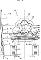
Fig. 1 is a schematic explanatory view showing a corresponding state of a knitting needle and a cam system in a flat knitting machine according to a first embodiment; -
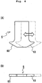
Figs. 2A to 2E are schematic configuration diagrams showing a selection presser comprising two divided pressers used inFig. 1 , whereFig. 2A is a front view of an outer side divided presser,Fig. 2B is a bottom view ofFig. 2A, Fig. 2C is a front view of an inner side divided presser,Fig. 2D is a bottom view ofFig. 2C, and Fig. 2E is a front view in a case where the outer side divided presser and the inner side divided presser are combined; -
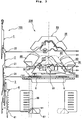
Fig. 3 is a schematic explanatory view showing a corresponding state of a knitting needle and a cam system in a flat knitting machine according to a second embodiment; -
Figs. 4A and 4B are schematic configuration diagrams showing a selection presser configured to be slidable in a moving direction of a carriage used inFig. 3 , whereFig. 4A is a front view of the selection presser andFig. 4B is a bottom view ofFig. 4A ; and -
Fig. 5 is a schematic configuration diagram showing a corresponding state of a knitting needle and a cam system in a conventional flat knitting machine. - Hereinafter, embodiments of the present invention will be described with reference to the drawings. A flat knitting machine of the present invention has a characteristic in the configuration of a half presser (selection presser) and a selector raising cam (raising butt raising cam) of the cam system, and the other configurations are the same as the conventional flat knitting machine described with reference to
Fig. 5 . Therefore, in the following embodiments, the difference with the conventional flat knitting machine will be mainly described. The chain dashed line inFigs. 1 and3 is the center line of the cam system. -
Half pressers Fig. 1 have the same length in the left and right direction in the plane of drawing as theconventional half pressers Fig. 5 . The arrangement is also the same as in the related art. The difference with the related art lies in that thehalf pressers presser 7A (8A) and inner side dividedpresser 7B (8B), in a direction along a travel path of the selectingbutt 31 of the H position (first position). The inner side dividedpresser 7B arranged on the center line side of thecam system 200 is formed to a length capable of sinking the selectingbutt 31 in the needle groove thus sinking theknitting needle butt 21 in the needle groove before theknitting butt 21 makes contact with the fixedneedle raising cam 80. The outer side dividedpresser 7A (8A) can be oscillated in the up and down direction in the plane of drawing independent from the inner side dividedpresser 7B (8B) by a retraction mechanism configured by an appropriate actuator such as a solenoid. However, an acting state in which only theouter side presser 7A (8A) remains on the travel path is not obtained. - First, the detailed configuration of the
half pressers Fig. 2 . Thehalf pressers half presser 7 is illustrated inFig. 2 . - As shown in
Figs. 2A and 2C , the outer side dividedpresser 7A as well as the inner side dividedpresser 7B are flat plate-like members, and are arranged on a cam plate in a direction the lower end face projects out from the cam plate shown inFigs. 2B and 2D (see alsoFig. 1 ). - The outer side divided
presser 7A includes arecess 71 comprising a through-hole that is bored through the outer side dividedpresser 7A in a plate thickness direction, and a thin thickness portion (second thin thickness portion) 72 formed from an edge on the inner side dividedpresser 7B side of therecess 71 towards an edge on the right side in the plane of drawing of the outer side dividedpresser 7A. Therecess 71 may not be a through-hole and may be merely a depression since it simply needs to be formed so that adistal end 75 of the inner side dividedpresser 7B, to be described later, can be fitted in. - The portion from an intermediate portion in the width direction of the outer side divided
presser 7A to the edge on the side opposite to thethin thickness portion 72 of the lower end face of the outer side dividedpresser 7A is inclined in the longitudinal direction of the outer side dividedpresser 7A, that is, towards the far direction in the plane of drawing ofFig. 1 . Because of the inclination of aninclined surface 70, the selectingbutt 31 can be smoothly sunk into the needle groove without being damaged. - The inner side divided
presser 7B is formed with a bulging-out portion 73 bulging out towards the outer side dividedpresser 7A side. A thin thickness portion (first thin thickness portion) 74 thinner than other portions is formed at the intermediate portion of the bulging-out portion 73. Thus, as shown inFig. 2E , thethin thickness portions presser 7A and the inner side dividedpresser 7B are overlapped to become onehalf presser 7. In this case, thedistal end 75 at the distal end of thethin thickness portion 74 in the bulging-out portion 73 is arranged in therecess 71 of the outer side dividedpresser 7A, and the thickness and the strength are ensured in theentire half presser 7. The engagement of the dividedpressers out portion 73 of the inner side dividedpresser 7B, and of the outer side dividedpresser 7A. Furthermore, even if the bulging-out portion 73 is overlapping with the outer side dividedpresser 7A, a step height formed in between can be reduced when the inner side dividedpresser 7B and the outer side dividedpresser 7A are combined. If the step height becomes large, either one of the divided pressers may not act on the selectingbutt 31 when the dividedpressers half presser 7. - Both sides of the lower end face of the inner side divided
presser 7B are inclined to the upper end side of the inner side dividedpresser 7B towards the edge in the width direction of the inner side dividedpresser 7B.Inclined surfaces butt 31 into the needle bed, similar to theinclined surface 70 of the outer side dividedpresser 7A. Theinclined surface 78 includes thedistal end 75 having a predetermined thickness, and thus has sufficient strength. - The
selector raising cam 87 of the present embodiment has the same shape as the related art, but the position in thecam system 200 is closer to the center line side of thecam system 200 than the related art (seeFig. 1 ). The position is determined so that theselector raising cam 87 starts to act on the raisingbutt 41 between (1) and (2) below. This position is the position of the dotted line at the middle of the three dotted lines extending in the up and down direction in the figure, and is the position of a branched point BP where the selectingbutt 31 transitions from the H position to the A position. - (1) In the figure, a position of the dotted line on the left side. This position is the position where the outer side divided
presser 7A acts on the selectingbutt 31 when the outer side dividedpresser 7A is in the acting state. - (2) In the figure, a position of the dotted line on the right side. This position is the position where the inner side divided
presser 7B acts on the selectingbutt 31 when only the inner side dividedpresser 7B is in the acting state. - The positions of (1) and (2) described above do not correspond to the left end of each divided
presser 7A (7B) because the inclined surface 70 (78) (seeFig. 2 ) is formed at the left end of each dividedpresser 7A (7B). - With reference to
Fig. 1 , a description will now be given of the travel path of each butt arranged in the knitting needle in a case where the stitches are transferred bidirectionally between the front and back needle beds. In this case, the outer side dividedpresser 7A of thehalf presser 7 on the preceding side is in the non-acting state of being arranged at a position deviated from the travel path of the selectingbutt 31, and the inner side dividedpresser 7B is in the acting state of being arranged on the travel path. Thetuck presser 90 is in the non-acting state, the dividedpressers half presser 8 on the following side are both in the acting state, the movableneedle raising cam 83 is in the in-state, and thetransfer cam 88 is in the out-state. - In the
knitting needle 100 in which theselect jack 3 is remained at the H position with respect to thecam system 200 in the above-described state, the selectingbutt 31 is sunk into the needle groove by the inner side dividedpresser 7B. The position (hereinafter referred to as an in-position) where the selectingbutt 31 is sunk is closer to the center line side of thecam system 200 compared to thehalf presser 7 in which the dividedpressers cam system 200 so that the position of pushing up theselect jack 3 from the H position to the A position can also be brought closer to the center line side of thecam system 200. The length and the position of thehalf presser 7 are the same as theconventional half presser 91 described with reference toFig. 5 , and thus theselector raising cam 87 and theneedle selection actuator 99 for pushing up the selector 4 to the needle bed gap side are brought closer to the center line side of thecam system 200 than with the related art in the flat knitting machine of the present embodiment. As a result, the pitch of thecam system 200 in the carriage and the cam system (not shown) adjacent to therelevant cam system 200 can be reduced, and the reciprocating stroke of the carriage can be reduced, whereby the knitting efficiency can be enhanced as a result. The carriage, on which the cam system is mounted, can be miniaturized since the pitch between the adjacent cam systems can be reduced. - The
knitting butt 21 can reliably pass thestitch cam 86 without being pulled down by thestitch cam 86 since the outer side dividedpresser 8A is in the acting state in thehalf presser 8 on the following side. Thus, theknitting needle 100 that has received the stitch will not be pulled down by thestitch cam 86 in the receiving operation of the stitches. - In a second embodiment, with reference to
Figs. 3 ,4A and 4B , a description will be given of a flat knitting machine including a half presser different from the first embodiment. The flat knitting machine of the second embodiment is similar to the first embodiment other than the configuration of the half presser. - The two
half pressers half pressers conventional half presser 91 shown inFig. 5 , but are configured to be able to oscillate so as to switch to the acting state and the non-acting state similar to thehalf presser 91. The oscillating direction is the up and down direction in the plane of drawing inFigs. 3 and4B , and is the depth direction in the plane of drawing inFig. 4A . In addition to the conventional configuration, thehalf presser butt 31 at the H position. Thehalf pressers conventional half pressers Fig. 5 when slid to the farthest position from the center line of thecam system 200. Thehalf pressers butt 31 in the needle groove before theknitting butt 21 comes into contact with the fixedneedle raising cam 80 even when slid to the nearest position from the center line. The configuration of oscillating or sliding the half presser may appropriately adopt the actuator such as the solenoid. - The position of the
selector raising cam 87 of the present embodiment is determined such that theselector raising cam 87 starts to act on the raisingbutt 41 between (3) and (4) below. This position is the position of the dotted line at the middle of the three dotted lines extending in the up and down direction in the figure, and is the position of the branched point BP where the selectingbutt 31 transitions from the H position to the A position. - (3) In the figure, a position of dotted line on the left side. This position is the position where the
half presser 6 is in the acting state and acts on the selectingbutt 31 when slid to the farthest position from the center line of thecam system 200. - (4) In the figure, a position of dotted line on the right side. This position is the position where the
half presser 6 is in the acting state and acts on the selectingbutt 31 when slid to the nearest position from the center line of thecam system 200. - The positions of (3) and (4) described above do not correspond to the left end of the
half presser 6 because an inclined surface 60 (seeFig. 4 ) is formed at the left end of thehalf presser 6. Theinclined surface 61 is an inclined surface for gradually emerging the selectingbutt 31 from the needle groove. - With reference to
Fig. 3 , a description will now be given of the travel path of each butt arranged in the knitting needle in a case where the stitches are transferred bidirectionally between the front and back needle beds. In this case, thehalf presser 6 on the preceding side is slid towards the center line side of thecam system 200 while being arranged on the travel path of the selectingbutt 31, and the half presser 9 on the following side is slid towards the side of moving away from the center line of thecam system 200 while being arranged on the travel path. Thetuck presser 90 is in the non-acting state, the movableneedle raising cam 83 is in the in-state, and thetransfer cam 88 is in the out-state. - In the
cam system 200 in the state described above as well, the position (hereinafter referred to as an in-position) where the selectingbutt 31 is sunk can be brought closer towards the center line of thecam system 200 compared to the conventional flat knitting machine described with reference toFig. 5 , similar to the first embodiment. As the in-position is closer to the center line side of thecam system 200, the position of pushing up theselect jack 3 from the H position to the A position can also be brought closer to the center line side of thecam system 200. As a result, the knitting efficiency can be enhanced and the miniaturization of the carriage mounted with the cam system can be achieved due to reasons similar to the first embodiment. - In the first and second embodiments, the
knitting needle 100 is configured by four members, but such a configuration is not the sole case. For example, the knitting needle may be configured by two members or three members. In this case, the knitting needle is configured by the needle main body 1 and another member. In either case, the knitting needle merely needs to include theknitting butt 21, the selectingbutt 31, and the raisingbutt 41. - In the flat knitting machine of the first and second embodiments, the selecting
butt 31 is allocated to three positions after the needle selection of two stages, but the configuration of the present invention can also be applied to the flat knitting machine in which the selectingbutt 31 is allocated to three positions after the needle selection of one stage (refer toWO 2004/003275 , for example). In this case as well, the H position at the middle of the three positions is the first position in the present invention, and the A position is the second position in the present invention. - In the flat knitting machine of the first to fourth embodiments, the configuration in which the selecting
butt 31 can take three positions is adopted, but the configuration of the present invention can also be applied to the flat knitting machine in which the selecting butt can only take two positions. In this case, one of the two positions is the first position and the other is the second position. - The embodiments of the present invention are not limited to the embodiments described above, and may be appropriately changed within a scope not deviating from the gist of the present invention. For example, in the configuration of the first embodiment, the half presser may be configured to go in and out in a direction perpendicular to the cam plate so as to be in the non-acting state with respect to the selecting butt when the half presser is in the in-state. The needle selection actuator may be an electromagnetic type as shown in Japanese Patent No.
3459514
Claims (5)
- A flat knitting machine comprising:at least a pair of front and back needle beds;a knitting needle (100) arranged in each of a plurality of needle grooves arranged side by side in a longitudinal direction of each needle bed; anda cam system (200) for causing the knitting needle (100) to carry out a knitting operation by acting on a plurality of butts arranged on the knitting needle (100) to advance and retreat the knitting needle (100) in the longitudinal direction of the needle groove;the knitting needle including,a knitting butt (21) for advancing and retreating the knitting needle (100) when acted upon by the cam system (200),a selecting butt (31) that sequentially takes at least two positions, a first position and a second position, towards a needle bed gap side in a longitudinal direction of the knitting needle (100), and changes the knitting operation to be carried out by the knitting needle (100) according to the position, anda raising butt (41) for changing the position of the selecting butt (31);the cam system (200) including,a needle raising cam (80) that acts on the knitting butt (21) to advance the knitting needle (100) when the selecting butt (31) is at the second position,stitch cams (85, 86), arranged in a pair on left and right of the needle raising cam (80), for retreating the knitting needle (100) advanced by the action of the needle raising cam (80),a pair of left and right selection pressers (7, 8; 6, 6) that take two states, an acting state of projecting out on a travel path of the selecting butt (31) to sink the selecting butt (31) in the needle groove and a non-acting state of not projecting out on the travel path and not acting on the selecting butt (31) when the selecting butt (31) is at the first position, anda pair of left and right raising butt raising cams (87, 87) for pushing up the raising butt (41) towards the needle bed gap to move the selecting butt (31) from the first position to the second position,wherein the cam system (200) reciprocates along the longitudinal direction of the needle beds when knitting a knitted fabric; andthe selection pressers (7, 8; 6, 6) are formed to a length capable of sinking the selecting butt (31) in the needle groove to sink the knitting butt (21) in the needle groove so that the knitting butt (21) does not act on the stitch cam (85, 86) when on a following side in an advancing direction of the cam system (200);the flat knitting machine characterized in thatthe raising butt raising cam (87, 87) is positioned such that a branched point (BP)where the selecting butt (31) transitions from the first position to the second position overlaps with the selection presser (7, 8; 6, 6) on the preceding side as the raising butt raising cam (87, 87) acts on the raising butt (41) on the preceding side in the advancing direction; anda retraction mechanism for retracting part or all of the selection presser (7, 8; 6, 6) from the acting state at the position overlapping with the branched point (BP) is arranged.
- The flat knitting machine according to claim 1, characterized in that
the selection pressers (7, 8) may be each divided into two, an outer side divided presser (7A, 8A) at a position away from a center line of the cam system (200) and an inner side divided presser (7B, 8B) at a position close to the center line;
the retraction mechanism is configured to switch each of the divided pressers (7A, 8A, 7B, 8B) to the acting state and the non-acting state independent from each other; and
the raising butt raising cam (87, 87) is positioned so that the raising butt raising cam (87, 87) acts on the raising butt (41) between
a position where the outer side divided presser (7A, 8A) acts on the selecting butt (31) when the outer side divided presser (7A, 8A) is in the acting state, and
a position where the inner side divided presser (7B, 8B) acts on the selecting butt (31) when only the inner side
divided presser (7A, 8B) is in the acting state. - The flat knitting machine according to claim 2, characterized in that
the inner side divided presser (7B, 8B) includes a bulging-out portion (73) that bulges out towards the outer side divided presser (7A, 8A) and overlaps with the outer side divided presser (7A, 8A), the bulging-out portion (73) having an inclined surface (78) gradually inclined towards its edge. - The flat knitting machine according to claim 3, characterized in that
the bulging-out portion (73) has a distal end (75) and a first thin thickness portion (74) formed thinner than the distal end (75); and
the outer side divided presser (7A, 8A) has a second thin thickness portion (72) formed thin in correspondence with the first thin thickness portion (74), and a recess (71) for receiving the distal end (75). - The flat knitting machine according to claim 1, characterized in that
the retraction mechanism is configured to slide the selection presser (6, 6) in a direction along the travel path towards the center line of the cam system (200) from the position overlapping with the branched point (BP); and
the raising butt raising cam (87, 87) is positioned so that the raising butt raising cam (87, 87) acts on the raising butt (41) between,
a position where the selection presser (6, 6) acts on the selecting butt (31) when the selection presser (6, 6) slides away from the center line of the cam system (200) on the travel path, and
a position where the selection presser (6, 6) acts on the selecting butt (31) when the selection presser (6, 6) slides towards the center line of the cam system (200) on the travel path.
Applications Claiming Priority (1)
| Application Number | Priority Date | Filing Date | Title |
|---|---|---|---|
| JP2010292528A JP5788675B2 (en) | 2010-12-28 | 2010-12-28 | Flat knitting machine |
Publications (2)
| Publication Number | Publication Date |
|---|---|
| EP2471984A1 EP2471984A1 (en) | 2012-07-04 |
| EP2471984B1 true EP2471984B1 (en) | 2017-06-14 |
Family
ID=45445737
Family Applications (1)
| Application Number | Title | Priority Date | Filing Date |
|---|---|---|---|
| EP11010256.3A Active EP2471984B1 (en) | 2010-12-28 | 2011-12-28 | Flat knitting machine |
Country Status (4)
| Country | Link |
|---|---|
| EP (1) | EP2471984B1 (en) |
| JP (1) | JP5788675B2 (en) |
| KR (1) | KR101537941B1 (en) |
| CN (1) | CN102560857B (en) |
Families Citing this family (5)
| Publication number | Priority date | Publication date | Assignee | Title |
|---|---|---|---|---|
| CN102787439B (en) * | 2012-09-04 | 2014-04-09 | 东莞市金贝诺软件技术有限公司 | Improved head cam system for computerized flat knitting machine |
| CN103409925A (en) * | 2013-08-08 | 2013-11-27 | 浙江嘉普控制技术有限公司 | Cam bottom plate of fully-automatic computer multifunctional flat knitting machine |
| CN108374231B (en) * | 2018-04-04 | 2024-03-22 | 浙江睿丰智能科技有限公司 | Knitting system for flat knitting machine |
| CN111733512B (en) * | 2020-07-13 | 2024-04-09 | 桐乡市强隆机械有限公司 | Single-groove double-needle plate device |
| CN112030334B (en) * | 2020-09-02 | 2021-08-17 | 浙江海森纺机科技有限公司 | Triangle control mechanism and rapid knitting method |
Family Cites Families (7)
| Publication number | Priority date | Publication date | Assignee | Title |
|---|---|---|---|---|
| JPH01104863A (en) * | 1987-10-12 | 1989-04-21 | Shima Seiki Mfg Ltd | Knitting cam |
| JP3459514B2 (en) * | 1995-06-15 | 2003-10-20 | 株式会社島精機製作所 | Needle selection device in flat knitting machine |
| AU2003242017A1 (en) * | 2002-06-26 | 2004-01-19 | Shima Seiki Manufacturing Limited | Needle selection device of weft knitting machine |
| JP4015982B2 (en) * | 2003-10-10 | 2007-11-28 | 株式会社島精機製作所 | Cam apparatus for knitting fabric |
| JP4336305B2 (en) * | 2004-12-27 | 2009-09-30 | 株式会社島精機製作所 | Combined cam system |
| JP5057996B2 (en) * | 2005-12-27 | 2012-10-24 | 株式会社島精機製作所 | Needle selector of flat knitting machine |
| CN101796233B (en) * | 2007-09-05 | 2011-11-16 | 株式会社岛精机制作所 | Weft knitting machine |
-
2010
- 2010-12-28 JP JP2010292528A patent/JP5788675B2/en active Active
-
2011
- 2011-12-12 KR KR1020110132625A patent/KR101537941B1/en active IP Right Grant
- 2011-12-16 CN CN201110421810.0A patent/CN102560857B/en active Active
- 2011-12-28 EP EP11010256.3A patent/EP2471984B1/en active Active
Also Published As
| Publication number | Publication date |
|---|---|
| KR101537941B1 (en) | 2015-07-20 |
| JP2012140715A (en) | 2012-07-26 |
| KR20120075364A (en) | 2012-07-06 |
| JP5788675B2 (en) | 2015-10-07 |
| EP2471984A1 (en) | 2012-07-04 |
| CN102560857A (en) | 2012-07-11 |
| CN102560857B (en) | 2015-06-24 |
Similar Documents
| Publication | Publication Date | Title |
|---|---|---|
| EP2471984B1 (en) | Flat knitting machine | |
| EP1835059B1 (en) | Complex cam system | |
| US5398527A (en) | Flat knitting machine having a transferring mechanism | |
| JP5913427B2 (en) | How to increase | |
| EP2196569A1 (en) | Weft knitting machine | |
| JP2007231447A (en) | Knitting cam device of flat knitting machine | |
| EP2025785A1 (en) | Knitting method of intersia pattern fabric and weft knitting machine | |
| EP2390395B1 (en) | Weft knitting machine and stitch transfer method for same | |
| KR102366041B1 (en) | Flat knitting machine | |
| US6688140B2 (en) | Weft knitting machine with transfer mechanism and transferring method | |
| EP3978669B1 (en) | Flatbed knitting machine | |
| JP5719557B2 (en) | Needle selector | |
| EP2392710B1 (en) | Flat knitting machine | |
| JP5632277B2 (en) | Compound needle of flat knitting machine | |
| EP4253625A1 (en) | Flatbed knitting machine and its needle selection mechanism | |
| EP4306698A1 (en) | Method for knitting punch-lace knitted fabric produced by flat-knitting machine | |
| CN115142183B (en) | Needle selecting device and method of flat knitting machine | |
| JP2020169432A (en) | Flat-knitting machine | |
| KR20020094055A (en) | Weft knitting machine with transfer mechanism |
Legal Events
| Date | Code | Title | Description |
|---|---|---|---|
| AK | Designated contracting states |
Kind code of ref document: A1 Designated state(s): AL AT BE BG CH CY CZ DE DK EE ES FI FR GB GR HR HU IE IS IT LI LT LU LV MC MK MT NL NO PL PT RO RS SE SI SK SM TR |
|
| AX | Request for extension of the european patent |
Extension state: BA ME |
|
| PUAI | Public reference made under article 153(3) epc to a published international application that has entered the european phase |
Free format text: ORIGINAL CODE: 0009012 |
|
| 17P | Request for examination filed |
Effective date: 20130103 |
|
| GRAP | Despatch of communication of intention to grant a patent |
Free format text: ORIGINAL CODE: EPIDOSNIGR1 |
|
| RIC1 | Information provided on ipc code assigned before grant |
Ipc: D04B 15/36 20060101AFI20161128BHEP |
|
| INTG | Intention to grant announced |
Effective date: 20161223 |
|
| GRAS | Grant fee paid |
Free format text: ORIGINAL CODE: EPIDOSNIGR3 |
|
| GRAA | (expected) grant |
Free format text: ORIGINAL CODE: 0009210 |
|
| AK | Designated contracting states |
Kind code of ref document: B1 Designated state(s): AL AT BE BG CH CY CZ DE DK EE ES FI FR GB GR HR HU IE IS IT LI LT LU LV MC MK MT NL NO PL PT RO RS SE SI SK SM TR |
|
| REG | Reference to a national code |
Ref country code: GB Ref legal event code: FG4D |
|
| REG | Reference to a national code |
Ref country code: CH Ref legal event code: EP Ref country code: AT Ref legal event code: REF Ref document number: 901045 Country of ref document: AT Kind code of ref document: T Effective date: 20170615 |
|
| REG | Reference to a national code |
Ref country code: IE Ref legal event code: FG4D |
|
| REG | Reference to a national code |
Ref country code: DE Ref legal event code: R096 Ref document number: 602011038633 Country of ref document: DE |
|
| REG | Reference to a national code |
Ref country code: NL Ref legal event code: MP Effective date: 20170614 |
|
| REG | Reference to a national code |
Ref country code: LT Ref legal event code: MG4D |
|
| PG25 | Lapsed in a contracting state [announced via postgrant information from national office to epo] |
Ref country code: LT Free format text: LAPSE BECAUSE OF FAILURE TO SUBMIT A TRANSLATION OF THE DESCRIPTION OR TO PAY THE FEE WITHIN THE PRESCRIBED TIME-LIMIT Effective date: 20170614 Ref country code: GR Free format text: LAPSE BECAUSE OF FAILURE TO SUBMIT A TRANSLATION OF THE DESCRIPTION OR TO PAY THE FEE WITHIN THE PRESCRIBED TIME-LIMIT Effective date: 20170915 Ref country code: ES Free format text: LAPSE BECAUSE OF FAILURE TO SUBMIT A TRANSLATION OF THE DESCRIPTION OR TO PAY THE FEE WITHIN THE PRESCRIBED TIME-LIMIT Effective date: 20170614 Ref country code: NO Free format text: LAPSE BECAUSE OF FAILURE TO SUBMIT A TRANSLATION OF THE DESCRIPTION OR TO PAY THE FEE WITHIN THE PRESCRIBED TIME-LIMIT Effective date: 20170914 Ref country code: FI Free format text: LAPSE BECAUSE OF FAILURE TO SUBMIT A TRANSLATION OF THE DESCRIPTION OR TO PAY THE FEE WITHIN THE PRESCRIBED TIME-LIMIT Effective date: 20170614 Ref country code: HR Free format text: LAPSE BECAUSE OF FAILURE TO SUBMIT A TRANSLATION OF THE DESCRIPTION OR TO PAY THE FEE WITHIN THE PRESCRIBED TIME-LIMIT Effective date: 20170614 |
|
| REG | Reference to a national code |
Ref country code: AT Ref legal event code: MK05 Ref document number: 901045 Country of ref document: AT Kind code of ref document: T Effective date: 20170614 |
|
| PG25 | Lapsed in a contracting state [announced via postgrant information from national office to epo] |
Ref country code: NL Free format text: LAPSE BECAUSE OF FAILURE TO SUBMIT A TRANSLATION OF THE DESCRIPTION OR TO PAY THE FEE WITHIN THE PRESCRIBED TIME-LIMIT Effective date: 20170614 Ref country code: LV Free format text: LAPSE BECAUSE OF FAILURE TO SUBMIT A TRANSLATION OF THE DESCRIPTION OR TO PAY THE FEE WITHIN THE PRESCRIBED TIME-LIMIT Effective date: 20170614 Ref country code: RS Free format text: LAPSE BECAUSE OF FAILURE TO SUBMIT A TRANSLATION OF THE DESCRIPTION OR TO PAY THE FEE WITHIN THE PRESCRIBED TIME-LIMIT Effective date: 20170614 Ref country code: BG Free format text: LAPSE BECAUSE OF FAILURE TO SUBMIT A TRANSLATION OF THE DESCRIPTION OR TO PAY THE FEE WITHIN THE PRESCRIBED TIME-LIMIT Effective date: 20170914 Ref country code: SE Free format text: LAPSE BECAUSE OF FAILURE TO SUBMIT A TRANSLATION OF THE DESCRIPTION OR TO PAY THE FEE WITHIN THE PRESCRIBED TIME-LIMIT Effective date: 20170614 |
|
| PG25 | Lapsed in a contracting state [announced via postgrant information from national office to epo] |
Ref country code: RO Free format text: LAPSE BECAUSE OF FAILURE TO SUBMIT A TRANSLATION OF THE DESCRIPTION OR TO PAY THE FEE WITHIN THE PRESCRIBED TIME-LIMIT Effective date: 20170614 Ref country code: SK Free format text: LAPSE BECAUSE OF FAILURE TO SUBMIT A TRANSLATION OF THE DESCRIPTION OR TO PAY THE FEE WITHIN THE PRESCRIBED TIME-LIMIT Effective date: 20170614 Ref country code: CZ Free format text: LAPSE BECAUSE OF FAILURE TO SUBMIT A TRANSLATION OF THE DESCRIPTION OR TO PAY THE FEE WITHIN THE PRESCRIBED TIME-LIMIT Effective date: 20170614 Ref country code: EE Free format text: LAPSE BECAUSE OF FAILURE TO SUBMIT A TRANSLATION OF THE DESCRIPTION OR TO PAY THE FEE WITHIN THE PRESCRIBED TIME-LIMIT Effective date: 20170614 Ref country code: AT Free format text: LAPSE BECAUSE OF FAILURE TO SUBMIT A TRANSLATION OF THE DESCRIPTION OR TO PAY THE FEE WITHIN THE PRESCRIBED TIME-LIMIT Effective date: 20170614 |
|
| PG25 | Lapsed in a contracting state [announced via postgrant information from national office to epo] |
Ref country code: IS Free format text: LAPSE BECAUSE OF FAILURE TO SUBMIT A TRANSLATION OF THE DESCRIPTION OR TO PAY THE FEE WITHIN THE PRESCRIBED TIME-LIMIT Effective date: 20171014 Ref country code: PL Free format text: LAPSE BECAUSE OF FAILURE TO SUBMIT A TRANSLATION OF THE DESCRIPTION OR TO PAY THE FEE WITHIN THE PRESCRIBED TIME-LIMIT Effective date: 20170614 Ref country code: SM Free format text: LAPSE BECAUSE OF FAILURE TO SUBMIT A TRANSLATION OF THE DESCRIPTION OR TO PAY THE FEE WITHIN THE PRESCRIBED TIME-LIMIT Effective date: 20170614 |
|
| REG | Reference to a national code |
Ref country code: DE Ref legal event code: R097 Ref document number: 602011038633 Country of ref document: DE |
|
| PLBE | No opposition filed within time limit |
Free format text: ORIGINAL CODE: 0009261 |
|
| STAA | Information on the status of an ep patent application or granted ep patent |
Free format text: STATUS: NO OPPOSITION FILED WITHIN TIME LIMIT |
|
| PG25 | Lapsed in a contracting state [announced via postgrant information from national office to epo] |
Ref country code: DK Free format text: LAPSE BECAUSE OF FAILURE TO SUBMIT A TRANSLATION OF THE DESCRIPTION OR TO PAY THE FEE WITHIN THE PRESCRIBED TIME-LIMIT Effective date: 20170614 |
|
| 26N | No opposition filed |
Effective date: 20180315 |
|
| REG | Reference to a national code |
Ref country code: CH Ref legal event code: PL |
|
| GBPC | Gb: european patent ceased through non-payment of renewal fee |
Effective date: 20171228 |
|
| PG25 | Lapsed in a contracting state [announced via postgrant information from national office to epo] |
Ref country code: SI Free format text: LAPSE BECAUSE OF FAILURE TO SUBMIT A TRANSLATION OF THE DESCRIPTION OR TO PAY THE FEE WITHIN THE PRESCRIBED TIME-LIMIT Effective date: 20170614 |
|
| REG | Reference to a national code |
Ref country code: IE Ref legal event code: MM4A |
|
| PG25 | Lapsed in a contracting state [announced via postgrant information from national office to epo] |
Ref country code: LU Free format text: LAPSE BECAUSE OF NON-PAYMENT OF DUE FEES Effective date: 20171228 Ref country code: MT Free format text: LAPSE BECAUSE OF NON-PAYMENT OF DUE FEES Effective date: 20171228 |
|
| REG | Reference to a national code |
Ref country code: FR Ref legal event code: ST Effective date: 20180831 |
|
| REG | Reference to a national code |
Ref country code: BE Ref legal event code: MM Effective date: 20171231 |
|
| PG25 | Lapsed in a contracting state [announced via postgrant information from national office to epo] |
Ref country code: IE Free format text: LAPSE BECAUSE OF NON-PAYMENT OF DUE FEES Effective date: 20171228 Ref country code: FR Free format text: LAPSE BECAUSE OF NON-PAYMENT OF DUE FEES Effective date: 20180102 |
|
| PG25 | Lapsed in a contracting state [announced via postgrant information from national office to epo] |
Ref country code: LI Free format text: LAPSE BECAUSE OF NON-PAYMENT OF DUE FEES Effective date: 20171231 Ref country code: CH Free format text: LAPSE BECAUSE OF NON-PAYMENT OF DUE FEES Effective date: 20171231 Ref country code: GB Free format text: LAPSE BECAUSE OF NON-PAYMENT OF DUE FEES Effective date: 20171228 Ref country code: BE Free format text: LAPSE BECAUSE OF NON-PAYMENT OF DUE FEES Effective date: 20171231 |
|
| PG25 | Lapsed in a contracting state [announced via postgrant information from national office to epo] |
Ref country code: MC Free format text: LAPSE BECAUSE OF FAILURE TO SUBMIT A TRANSLATION OF THE DESCRIPTION OR TO PAY THE FEE WITHIN THE PRESCRIBED TIME-LIMIT Effective date: 20170614 Ref country code: HU Free format text: LAPSE BECAUSE OF FAILURE TO SUBMIT A TRANSLATION OF THE DESCRIPTION OR TO PAY THE FEE WITHIN THE PRESCRIBED TIME-LIMIT; INVALID AB INITIO Effective date: 20111228 |
|
| PG25 | Lapsed in a contracting state [announced via postgrant information from national office to epo] |
Ref country code: CY Free format text: LAPSE BECAUSE OF NON-PAYMENT OF DUE FEES Effective date: 20170614 |
|
| PG25 | Lapsed in a contracting state [announced via postgrant information from national office to epo] |
Ref country code: MK Free format text: LAPSE BECAUSE OF FAILURE TO SUBMIT A TRANSLATION OF THE DESCRIPTION OR TO PAY THE FEE WITHIN THE PRESCRIBED TIME-LIMIT Effective date: 20170614 |
|
| PG25 | Lapsed in a contracting state [announced via postgrant information from national office to epo] |
Ref country code: TR Free format text: LAPSE BECAUSE OF FAILURE TO SUBMIT A TRANSLATION OF THE DESCRIPTION OR TO PAY THE FEE WITHIN THE PRESCRIBED TIME-LIMIT Effective date: 20170614 |
|
| PG25 | Lapsed in a contracting state [announced via postgrant information from national office to epo] |
Ref country code: PT Free format text: LAPSE BECAUSE OF FAILURE TO SUBMIT A TRANSLATION OF THE DESCRIPTION OR TO PAY THE FEE WITHIN THE PRESCRIBED TIME-LIMIT Effective date: 20170614 |
|
| PG25 | Lapsed in a contracting state [announced via postgrant information from national office to epo] |
Ref country code: AL Free format text: LAPSE BECAUSE OF FAILURE TO SUBMIT A TRANSLATION OF THE DESCRIPTION OR TO PAY THE FEE WITHIN THE PRESCRIBED TIME-LIMIT Effective date: 20170614 |
|
| PGFP | Annual fee paid to national office [announced via postgrant information from national office to epo] |
Ref country code: IT Payment date: 20231110 Year of fee payment: 13 Ref country code: DE Payment date: 20231031 Year of fee payment: 13 |