JP2012140715A - Flat-knitting machine - Google Patents
Flat-knitting machine Download PDFInfo
- Publication number
- JP2012140715A JP2012140715A JP2010292528A JP2010292528A JP2012140715A JP 2012140715 A JP2012140715 A JP 2012140715A JP 2010292528 A JP2010292528 A JP 2010292528A JP 2010292528 A JP2010292528 A JP 2010292528A JP 2012140715 A JP2012140715 A JP 2012140715A
- Authority
- JP
- Japan
- Prior art keywords
- presser
- selection
- needle
- bat
- knitting
- Prior art date
- Legal status (The legal status is an assumption and is not a legal conclusion. Google has not performed a legal analysis and makes no representation as to the accuracy of the status listed.)
- Granted
Links
Images


Classifications
-
- D—TEXTILES; PAPER
- D04—BRAIDING; LACE-MAKING; KNITTING; TRIMMINGS; NON-WOVEN FABRICS
- D04B—KNITTING
- D04B7/00—Flat-bed knitting machines with independently-movable needles
-
- D—TEXTILES; PAPER
- D04—BRAIDING; LACE-MAKING; KNITTING; TRIMMINGS; NON-WOVEN FABRICS
- D04B—KNITTING
- D04B15/00—Details of, or auxiliary devices incorporated in, weft knitting machines, restricted to machines of this kind
- D04B15/32—Cam systems or assemblies for operating knitting instruments
- D04B15/36—Cam systems or assemblies for operating knitting instruments for flat-bed knitting machines
- D04B15/362—Cam systems or assemblies for operating knitting instruments for flat-bed knitting machines with two needle beds in V-formation
- D04B15/365—Cam systems or assemblies for operating knitting instruments for flat-bed knitting machines with two needle beds in V-formation with provision for loop transfer from one needle bed to the other
-
- D—TEXTILES; PAPER
- D04—BRAIDING; LACE-MAKING; KNITTING; TRIMMINGS; NON-WOVEN FABRICS
- D04B—KNITTING
- D04B15/00—Details of, or auxiliary devices incorporated in, weft knitting machines, restricted to machines of this kind
- D04B15/28—Needle pressers
-
- D—TEXTILES; PAPER
- D04—BRAIDING; LACE-MAKING; KNITTING; TRIMMINGS; NON-WOVEN FABRICS
- D04B—KNITTING
- D04B15/00—Details of, or auxiliary devices incorporated in, weft knitting machines, restricted to machines of this kind
- D04B15/32—Cam systems or assemblies for operating knitting instruments
- D04B15/36—Cam systems or assemblies for operating knitting instruments for flat-bed knitting machines
-
- D—TEXTILES; PAPER
- D04—BRAIDING; LACE-MAKING; KNITTING; TRIMMINGS; NON-WOVEN FABRICS
- D04B—KNITTING
- D04B15/00—Details of, or auxiliary devices incorporated in, weft knitting machines, restricted to machines of this kind
- D04B15/66—Devices for determining or controlling patterns ; Programme-control arrangements
- D04B15/68—Devices for determining or controlling patterns ; Programme-control arrangements characterised by the knitting instruments used
- D04B15/70—Devices for determining or controlling patterns ; Programme-control arrangements characterised by the knitting instruments used in flat-bed knitting machines
Abstract
Description
本発明は、従来よりも編成効率に優れる横編機に関する。 The present invention relates to a flat knitting machine that is more excellent in knitting efficiency than conventional ones.
横編機は、少なくとも前後一対の針床と、各針床に並設される多数の針溝のそれぞれに配置される編針と、針床の長手方向に沿って往復運動するキャリッジとを備える(例えば、特許文献1や2を参照)。キャリッジにはカムシステムが搭載されており、このカムシステムにより編針に編成動作(ニット、タック、ミス、および前後の針床間での編目の受け渡し)を行なわせる。
The flat knitting machine includes at least a pair of front and rear needle beds, a knitting needle disposed in each of a large number of needle grooves arranged in parallel to each needle bed, and a carriage that reciprocates along the longitudinal direction of the needle bed ( For example, see
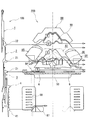
これらの編成動作は、カムシステムと共にキャリッジに備わる選針アクチュエーターにより編針の動作を制御することにより行われる。図5は、編針100とカムシステム200との対応状態を示す概略説明図である。この図5では、説明の便宜上、カムシステム200の一部のみを示す。また、図中には、編目の目移しを行う際、編針に備わる一部のバットがカムシステム200上に描く走行軌道を示す。
These knitting operations are performed by controlling the operation of the knitting needles with a needle selection actuator provided on the carriage together with the cam system. FIG. 5 is a schematic explanatory view showing a correspondence state between the knitting
特許文献1,2に示す横編機の編針100は、フックを有するニードル本体1と、ニードル本体1を針溝の長手方向に進退させるニードルジャック2と、ニードルジャック2を進退させるか否かを制御するセレクトジャック3と、針溝の長手方向におけるセレクトジャック3のポジションを変化させるセレクタ4とを有する。このような編針100は、揺動式あるいは直動式の選針アクチュエーター99による二段階の選針を受けて、その選針の結果とカムシステム200の状態に応じた編成動作を行う。編針100の選針は、選針アクチュエーター99により選針されたセレクタ4により、針溝の長手方向におけるセレクトジャック3のポジションを変えることで行われる。セレクトジャック3のポジションには、Bポジション、Bポジションよりも歯口側(ニードル本体1側)のHポジション、Hポジションよりも歯口側のAポジションの三つがある。
The knitting
上記セレクトジャック3のポジションに応じてニードル本体1を針溝沿いに移動させるニードルジャック2には、編成用バット21および目移し用バット22が設けられている。これらバット21,22にカムシステム200が作用することで、ニードルジャック2が針溝に沿って進退し、編成動作が行われる。代表して、対向する編針から編目を受ける動作と、対向する編針に編目を渡す動作について説明する。
The
まず、編目の受け動作について説明する。編目の受け動作を行うにあたって、セレクトジャック3は、一段階目の選針を経てHポジション(第1ポジション)となっており、カムシステム200の可動ニードルレイジングカム83は没状態、トランスファーカム88,89は出状態(カム89は常に出状態で没状態とはならない)、ハーフプレッサ91,92は、セレクトジャック3の先端部に形成される選択用バット31の走行軌道上に配置され、タックプレッサ(選択プレッサ)90は当該走行軌道上から退避している。
First, the stitch receiving operation will be described. In performing the stitch receiving operation, the
このような配置でキャリッジが走行すると、選択用バット31が、カムシステム200のハーフプレッサ91により針溝内に沈み込まされ、それによってセレクトジャック3の先端部が、ニードルジャック2の中間部を湾曲させ、ニードルジャック2の編成用バット21を針溝に沈ませる。その結果、ニードルジャック2の編成用バット21に固定ニードルレイジングカム80が作用せず、ニードルジャック2は針溝に沿って移動しない。
When the carriage travels in such an arrangement, the
次に、選択用バット31が走行軌道上にあるハーフプレッサ91を通過し終わると、選択用バット31は針溝から浮上し、それに伴ってニードルジャック2に備わる両バット21,22も針溝から浮上する。その結果、編成用バット21に、固定ニードルレイジングカム80の中間部に形成される受け用トランスファーカム81が作用し、ニードル本体1が歯口側に突き上げられた後、目移し用バット22に、トランスファーカム88の下端面が作用し、ニードル本体1が歯口から離れる方向に引き下げられ、編目の受け動作が完了する。以降は、選択用バット31がハーフプレッサ92により針溝に沈み込まされ、それによって編成用バット21が度山カム86に接触することなく度山カム86を通過する。
Next, when the
次に、編目の渡し動作について説明する。編目の渡し動作を行うにあたって、セレクトジャック3は、一段階目の選針を経てHポジションとなった後、二段階目の選針を経てAポジション(第2ポジション)となっており、可動ニードルレイジングカム83は没状態、トランスファーカム88,89は出状態となっている。なお、ハーフプレッサ91,92、およびタックプレッサ90は、Hポジションの走行軌道から退避した状態であってもAポジションの走行軌道に重複しないので、これらプレッサ90,91,92の配置は問われない。
Next, the stitch transfer operation will be described. When performing the stitch transfer operation, the
上述した配置でキャリッジが走行すると、選択用バット31は一度も針溝内に沈み込まされることはなく、図示するように、バット21,22はカムシステム200に沿った走行軌道を描いて編目の渡し動作が行われる。
When the carriage travels in the above-described arrangement, the
近年では、横編機における更なる編成効率の向上が望まれており、既存のカムシステムに備わる各カムの配置や形状を見直すことが検討されている。 In recent years, further improvement in knitting efficiency in flat knitting machines has been desired, and it has been considered to review the arrangement and shape of each cam provided in an existing cam system.
本発明は、上記事情に鑑みてなされたものであり、その目的の一つは、従来よりも更に編成効率を向上させることができる横編機を提供することを目的とする。 The present invention has been made in view of the above circumstances, and an object of the present invention is to provide a flat knitting machine capable of further improving the knitting efficiency as compared with the conventional art.
本発明者は上記課題を解決するにあたり、以下の検討を行った結果、ハーフプレッサの構成に着目した。 In order to solve the above problems, the present inventor paid attention to the configuration of the half presser as a result of the following investigation.
編成過程において、1段階目の選針を経てHポジションとなった複数の編針100を、更に2段階目の選針でHポジションのままの編針100と、HポジションからAポジションに変更された編針100とに振り分ける場合がある。同一の編成コースで前後の針床間で双方向に編目の受け渡しをする場合がそれに該当する。既に説明したように、編目を渡す編針100はAポジション、編目を受ける編針100はHポジションとなる。
In the knitting process, a plurality of knitting
セレクトジャック3をHポジションからAポジションに上昇させるには、ハーフプレッサ91により選択用バット31が針溝に沈み込まされる前に、ハーフプレッサ91が作用しないAポジションに選択用バット31を突き上げる必要がある。そのため、選択用バット31がHポジション(第1ポジション)からAポジション(第2ポジション)に遷移する分岐点BPは、ハーフプレッサ91の外側(図5中に一点鎖線で示すカムシステム200の中心線から離れる側)に位置させる必要がある。つまり、セレクタ4の上げバット41を歯口側に突き上げるセレクタレイジングカム(上げバットレイジングカム)87の位置も、選針アクチュエーター99の位置も、ハーフプレッサ91により規定されることになる。参考までに図5中に、ハーフプレッサ91が選択用バット31に作用し始める位置(右側点線)と、セレクトジャック3をAポジションにするセレクタレイジングカム87が上げバット41に作用し始める位置(左側点線)とを示す。
In order to raise the
ここで、図5を見ると分かるように、先行側のハーフプレッサ91は、編成用バット21が固定ニードルレイジングカム80に接触するかなり前から選択用バット31を針溝内に沈み込ませている。つまり、ハーフプレッサ91は、先行側のハーフプレッサとして必要な長さよりも長いといえる。これは、編成方向が入れ替わってハーフプレッサ91が後行側のハーフプレッサとなったときに、ハーフプレッサ91が後行側のハーフプレッサとして必要な長さを有している必要があるからである。編成の後行側にあるハーフプレッサ92は、度山カム86による編針100の引き込みを避けることに用いられ、その際、編成用バット21が度山カム86を確実に通過できる長さが必要になる。従って、ハーフプレッサ91が後行側のハーフプレッサとなったときに、編成用バット21が度山カム85を確実に通過できる長さとなるようにハーフプレッサ91が設計されている。
Here, as can be seen from FIG. 5, the leading
以上説明した検討に基づいて、本発明者は、ハーフプレッサの構成を再検討し、本発明横編機を完成させた。その本発明横編機を以下に規定する。 Based on the examination described above, the present inventor has reviewed the configuration of the half presser and completed the flat knitting machine of the present invention. The flat knitting machine of the present invention is defined below.
本発明横編機は、少なくとも前後一対の針床と、各針床の長手方向に並列される複数の針溝のそれぞれに配置される編針と、編針に備わる複数のバットに作用して、編針を針溝の長手方向に進退させることで編針に編成動作を行わせるカムシステムと、を備え、編地の編成にあたってカムシステムが針床の長手方向に沿って往復する横編機である。 The flat knitting machine of the present invention acts on at least a pair of front and back needle beds, a knitting needle disposed in each of a plurality of needle grooves juxtaposed in the longitudinal direction of each needle bed, and a plurality of bats provided on the knitting needle, thereby And a cam system that causes the knitting needle to perform a knitting operation by advancing and retreating the needle in the longitudinal direction of the needle groove, and the cam system reciprocates along the longitudinal direction of the needle bed when knitting the knitted fabric.
横編機の編針は、編成用バットと選択用バットと上げバットとを備える。編成用バットは、カムシステムが作用することで編針を進退させる。選択用バットは、編針の長手方向に歯口側に向かって順次第1ポジションと第2ポジションの少なくとも二つのポジションを取り得、そのポジションに応じて編針に行わせる編成動作を異ならせる。上げバットは、選択用バットのポジションを変更させる。 The knitting needle of the flat knitting machine includes a knitting bat, a selection bat, and a raising bat. The knitting bat advances and retracts the knitting needle by the action of the cam system. The selection bat can sequentially take at least two positions of the first position and the second position in the longitudinal direction of the knitting needle toward the tooth mouth side, and varies the knitting operation performed on the knitting needle according to the position. The raising bat changes the position of the selection bat.
また、横編機のカムシステムは、ニードルレイジングカムと、ニードルレイジングカムの左右に一対設けられる度山カムと、左右一対の選択プレッサと、左右一対の上げバットレイジングカムとを備える。ニードルレイジングカムは、選択用バットが第2ポジションにあるときに編成用バットに作用して編針を進出させる。度山カムは、ニードルレイジングカムの作用により進出した編針を後退させる。両選択プレッサは、選択用バットが第1ポジションにあるときに、その選択用バットの走行軌道上に突出して選択用バットを針溝内に沈み込ませる作用状態、および走行軌道上に突出せずに選択用バットに作用しない不作用状態の二つの状態を取り得る。上げバットレイジングカムは、上げバットを歯口に向かって突き上げることで、選択用バットを第1ポジションから第2ポジションに移動させる。 The cam system of the flat knitting machine includes a needle raising cam, a pair of mountain cams provided on the left and right sides of the needle raising cam, a pair of left and right selection pressers, and a pair of left and right raised butt raising cams. The needle raising cam acts on the knitting bat to advance the knitting needle when the selection bat is in the second position. The Washiyama cam retracts the advanced knitting needle by the action of the needle raising cam. Both the selection pressers are in an operating state in which when the selection bat is in the first position, the selection bat protrudes on the traveling track of the selection bat and sinks the selection bat into the needle groove, and does not protrude on the traveling track. It is possible to take two states of non-acting that do not act on the selection bat. The raising bat raising cam moves the selection butt from the first position to the second position by pushing the raising butt toward the mouth.
上記構成を備える本発明横編機では、両選択プレッサは、カムシステムの進行方向の後行側となったときに、編成用バットが度山カムに作用しないように編成用バットを針溝内に沈み込ませるために、選択用バットを針溝内に沈み込ませる長さに形成されている。また、本発明横編機では、進行方向の先行側で上げバットに上げバットレイジングカムが作用するに伴い、選択用バットが第1ポジションから第2ポジションに遷移する分岐点が、先行側の選択プレッサに重複するように、上げバットレイジングカムが位置決めされている。そして、本発明横編機は、上記分岐点に重複する位置から選択プレッサの一部あるいは全部を退避させる退避機構を備えることを特徴とする。 In the flat knitting machine of the present invention having the above-described configuration, the both selection pressers are arranged so that the knitting bat is placed in the needle groove so that the knitting butt does not act on the mountain cam when the cam system is in the trailing direction of the cam system. In order to sink into the needle groove, the length of the selection bat is set into the needle groove. Further, in the flat knitting machine of the present invention, the branching point at which the selection butt transitions from the first position to the second position as the butt raising cam acts on the raising bat on the preceding side in the traveling direction is selected on the leading side. The raising butt raising cam is positioned so as to overlap the presser. The flat knitting machine of the present invention includes a retraction mechanism that retreats part or all of the selected presser from a position overlapping with the branch point.
本発明横編機の一形態として、両選択プレッサが、カムシステムの中心線から離れた位置にある外側分割プレッサと、中心線から近い位置にある内側分割プレッサとに二分割されていても良い。その場合、退避機構は、各分割プレッサをそれぞれ独立して作用状態と不作用状態に切り替える構成とする。そして、この横編機では、次の(1)と(2)の間で、上げバットに上げバットレイジングカムが作用するように上げバットレイジングカムが位置決めされている。
(1)外側分割プレッサが作用状態にあるときに外側分割プレッサが選択用バットに作用する位置。
(2)内側分割プレッサのみが作用状態にあるときに内側分割プレッサが選択用バットに作用する位置。
As one form of the flat knitting machine of the present invention, both selection pressers may be divided into two parts, an outer divided presser located at a position away from the center line of the cam system and an inner divided presser located at a position near the center line. . In that case, the retracting mechanism is configured to switch each divided presser independently between an operating state and a non-operating state. In this flat knitting machine, the raised butt-raising cam is positioned so that the raised butt-raising cam acts on the raised bat between the following (1) and (2).
(1) A position at which the outer divided presser acts on the selection bat when the outer divided presser is in the operating state.
(2) A position at which the inner divided presser acts on the selection bat when only the inner divided presser is in an operating state.
分割プレッサを備える本発明横編機の一形態として、内側分割プレッサは、外側分割プレッサに向かって張り出し、外側分割プレッサと重複する張出部を備えていても良い。その場合、張出部は、その縁部に向かうに従って緩やかに傾斜した傾斜面を備えることが好ましい。 As one form of this invention flat knitting machine provided with a division | segmentation presser, the inner side division presser may be provided with the overhang | projection part which protrudes toward the outer side division presser and overlaps with an outer side division presser. In that case, it is preferable that the overhang portion has an inclined surface that is gently inclined toward the edge.
また、張出部を備える内側分割プレッサとした場合、張出部は、先端部と、先端部よりも薄く形成された第一薄肉部と、を有し、外側分割プレッサは、第一薄肉部に対応して薄く形成された第二薄肉部と、先端部を受け入れる凹部と、を有することが好ましい。 Moreover, when it is set as the inner side division presser provided with an overhang | projection part, an overhang | projection part has a front-end | tip part and the 1st thin part formed thinner than the front-end | tip part, and an outer side division presser is a 1st thin-wall part. It is preferable to have the 2nd thin part thinly formed corresponding to, and the recessed part which receives a front-end | tip part.
また、本発明横編機の一形態として、退避機構は、両選択プレッサを分岐点に重複する位置からカムシステムの中心線に向かう走行軌道に沿った方向にスライドさせる構成であっても良い。そして、この横編機では、次の(3)と(4)の間で、上げバットに上げバットレイジングカムが作用するように上げバットレイジングカムが位置決めされている。
(3)選択プレッサが走行軌道上でカムシステムの中心線から遠ざかってスライドしたときに、選択プレッサが選択用バットに作用する位置。
(4)選択プレッサが走行軌道上でカムシステムの中心線に向かってスライドしたときに、選択プレッサが選択用バットに作用する位置。
Further, as one form of the flat knitting machine of the present invention, the retraction mechanism may be configured to slide both the selection pressers in a direction along the traveling track from the position overlapping the branch point toward the center line of the cam system. In this flat knitting machine, between the following (3) and (4), the raising bat raising cam is positioned so that the raising bat raising cam acts on the raising butt.
(3) A position where the selection presser acts on the selection bat when the selection presser slides away from the center line of the cam system on the traveling track.
(4) A position where the selection presser acts on the selection bat when the selection presser slides on the traveling track toward the center line of the cam system.
本発明横編機によれば、第1ポジションにある選択用バットに先行側の選択プレッサが作用する位置を、従来よりもカムシステムの中心線側に寄せることができる。つまり、選択用バットを第1ポジションから第2ポジションにする上げバットレイジングカム、および選針アクチュエーターの位置を、従来よりもカムシステムの中心線側に寄せることができる。そして、これらの構成を寄せた分だけ、一つのカムシステムから次のカムシステムまでのピッチを詰めることができ、その結果、キャリッジの往復ストロークを短くできるので、編成効率を向上させることができる。また、カムシステム間のピッチが詰まることにより、キャリッジを小型化・軽量化できるので、編成速度も向上させることができる。 According to the flat knitting machine of the present invention, the position where the selection presser on the preceding side acts on the selection bat in the first position can be brought closer to the center line side of the cam system than before. That is, the position of the raising bat-raising cam that changes the selection bat from the first position to the second position and the needle selection actuator can be brought closer to the center line side of the cam system than before. Then, the pitch from one cam system to the next cam system can be reduced by the amount corresponding to these arrangements. As a result, the reciprocating stroke of the carriage can be shortened, so that the knitting efficiency can be improved. Further, since the pitch between the cam systems is clogged, the carriage can be reduced in size and weight, so that the knitting speed can also be improved.
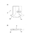
以下、本発明の実施形態を図に基づいて説明する。本発明の横編機は、カムシステムのうち、ハーフプレッサ(選択プレッサ)とセレクタレイジングカム(上げバットレイジングカム)の構成に特徴があり、これら以外の構成は、図5を参照する従来の横編機と同一である。従って、以下の実施形態では、主として従来の横編機との相違点を説明する。なお、図1,3における一点鎖線は、カムシステムの中心線である。 Hereinafter, embodiments of the present invention will be described with reference to the drawings. The flat knitting machine of the present invention is characterized by the configuration of a half presser (selection presser) and a selector raising cam (raised bat raising cam) in the cam system, and other configurations are the same as the conventional flat knitting machine shown in FIG. Same as knitting machine. Accordingly, in the following embodiment, differences from the conventional flat knitting machine will be mainly described. 1 and 3 is a center line of the cam system.
<実施形態1>
図1に示す本実施形態のハーフプレッサ7,8は、図5に示す従来のハーフプレッサ91,92と紙面左右方向に同じ長さを有する。また、その配置も従来と同じである。従来との相違点は、これらハーフプレッサ7,8が、Hポジション(第1ポジション)の選択用バット31の走行軌道に沿った方向に、外側分割プレッサ7A(8A)と内側分割プレッサ7B(8B)とに二分割されていることである。カムシステム200の中心線側に配される内側分割プレッサ7Bは、編成用バット21が固定ニードルレイジングカム80に接触する前に、選択用バット31を針溝内に沈み込ませ、それによって編成用バット21を針溝内に沈み込ませることができる長さに形成されている。これら外側分割プレッサ7A,(8A)は、ソレノイドなどの適宜なアクチュエーターで構成された退避機構により、内側分割プレッサ7B(8B)と独立して紙面上下方向に揺動させることができるようになっている。但し、外側プレッサ7A(8A)のみが走行軌道上に残る作用状態となることはない。
<Embodiment 1>
The
まず、ハーフプレッサ7,8の詳細な構成を図2に基づいて説明する。なお、ハーフプレッサ7,8は互いに左右対称な形状であるため、図2ではハーフプレッサ7のみ図示する。
First, a detailed configuration of the
図2(A),(C)に示すように、外側分割プレッサ7Aも内側分割プレッサ7Bも平板状の部材であって、図2(B),(D)に示す下端面がカムプレートから突出する方向にカムプレートに配置される(図1を合わせて参照)。
2A and 2C, both the outer divided
外側分割プレッサ7Aには、板厚方向に外側分割プレッサ7Aを貫通する貫通孔からなる凹部71と、凹部71の内側分割プレッサ7B側の縁部から外側分割プレッサ7Aの紙面右側の縁部に向かって形成される薄肉部(第二薄肉部)72とを有する。なお、凹部71は、後述する内側分割プレッサ7Bの先端部75が嵌め込むことができるように形成されていれば良いので、貫通孔ではなく単なる窪みであっても良い。
The outer divided
また、外側分割プレッサ7Aの下端面のうち、外側分割プレッサ7Aの幅方向の中間部から薄肉部72とは反対側の縁部までの部分は、外側分割プレッサ7Aの長手方向、即ち、図1の紙面奥方向に向かって傾斜している。この傾斜面70の傾斜によって選択用バット31を損傷することなく滑らかに針溝に沈み込ませることができる。
Further, of the lower end surface of the outer divided
一方、内側分割プレッサ7Bには、外側分割プレッサ7A側に張り出した張出部73が形成されている。張出部73の中間部分には、他の部分よりも薄い薄肉部(第一薄肉部)74が形成されている。そのため、図2(E)に示すように、外側分割プレッサ7Aと内側分割プレッサ7Bとが重なって一つのハーフプレッサ7となったとき、薄肉部72,74同士が重なる。その際、張出部73における薄肉部74よりも先端にある先端部75は、外側分割プレッサ7Aの凹部71に配置され、ハーフプレッサ7全体で厚みと強度が確保される。このような内側分割プレッサ7Bの張出部73と、外側分割プレッサ7Aの構成により、両分割プレッサ7A,7Bの係合を強固にできる。また、張出部73が外側分割プレッサ7Aに重複していても、内側分割プレッサ7Bと外側分割プレッサ7Aとを組み合わせたときに、両者の間に形成される段差を小さくすることができる。仮に段差が大きくなると、両分割プレッサ7A,7Bを組み合わせてハーフプレッサ7としたときに、いずれかの分割プレッサが選択用バット31に作用しなくなる恐れがある。
On the other hand, the
また、内側分割プレッサ7Bの下端面の両側は、内側分割プレッサ7Bの幅方向縁部に向かって内側分割プレッサ7Bの上端側に傾斜している。この傾斜により形成される傾斜面78,79も、外側分割プレッサ7Aの傾斜面70と同様に、選択用バット31を滑らかに針床に沈み込ませるためのものである。なお、傾斜面78は、所定の厚みを有する先端部75を含むので、十分な強度を備える。
Further, both sides of the lower end surface of the inner divided
一方、本実施形態のセレクタレイジングカム87は、その形状は、従来と同じであるが、カムシステム200おける位置が従来よりもカムシステム200の中心線側に寄っている(図1参照)。その位置は、次の(1)および(2)の間で、上げバット41にセレクタレイジングカム87が作用し始めるように決定されている。この位置は、図中の上下方向に伸びる三本の点線のうち、中央の点線の位置であり、選択用バット31がHポジションからAポジションに遷移する分岐点BPの位置である。
(1)図中、左側の点線の位置。この位置は、外側分割プレッサ7Aが作用状態にあるときに外側分割プレッサ7Aが選択用バット31に作用する位置である。
(2)図中、右側の点線の位置。この位置は、内側分割プレッサ7Bのみが作用状態にあるときに内側分割プレッサ7Bが選択用バット31に作用する位置である。
なお、上記(1)、(2)の位置が各分割プレッサ7A(7B)の左端に一致しないのは、各分割プレッサ7Aの左端に傾斜面70(78)(図2を参照)が形成されているからである。
On the other hand, the
(1) The position of the dotted line on the left side in the figure. This position is a position at which the outer divided
(2) The position of the dotted line on the right side in the figure. This position is a position at which the inner divided
The reason why the positions (1) and (2) do not coincide with the left end of each divided
次に、図1を参照して、前後の針床で双方向に編目の受け渡しを行ったときの編針に備わる各バットの走行軌道を説明する。その場合、先行側のハーフプレッサ7の外側分割プレッサ7Aは、選択用バット31の走行軌道から外れる位置に配置された不作用状態、内側分割プレッサ7Bは、当該走行軌道上に配置される作用状態となる。タックプレッサ90は不作用状態、後行側のハーフプレッサ8の両分割プレッサ8A,8Bは共に作用状態、可動ニードルレイジングカム83は没状態、トランスファーカム88は出状態となっている。
Next, with reference to FIG. 1, the travel trajectory of each bat provided on the knitting needle when the stitch is transferred bi-directionally between the front and back needle beds will be described. In that case, the outer divided
上述した状態のカムシステム200に対して、セレクトジャック3をHポジションのままとした編針100では、選択用バット31は内側分割プレッサ7Bにより針溝内に沈み込まされる。選択用バット31が沈み込まされる位置(以下、没位置)は、分割プレッサ7A,7Bが一体となったハーフプレッサ7に比べて、カムシステム200の中心線側に寄せられる。また、没位置が、カムシステム200の中心線側に寄っていることで、セレクトジャック3をHポジションからAポジションに突き上げる位置も、カムシステム200の中心線側に寄せることができる。ハーフプレッサ7の長さと位置は、図5を参照した従来のハーフプレッサ91と同じであるから、本実施形態の横編機では、セレクタ4を歯口側に突き上げるセレクタレイジングカム87と選針アクチュエーター99とが、従来よりもカムシステム200の中心線側に寄せられていることになる。その結果、キャリッジにおけるカムシステム200と、このカムシステム200に隣接するカムシステム(図示せず)とのピッチを詰め、キャリッジの往復ストロークを短くすることができ、その結果として編成効率を向上させることができる。また、隣接するカムシステム間のピッチが詰まることで、カムシステムを搭載するキャリッジをコンパクト化することができる。
In the
なお、後行側のハーフプレッサ8では外側分割プレッサ8Aが作用状態にあるため、編成用バット21は度山カム86により引き下げられることなく、度山カム86を確実に通過できる。そのため、編目の受け動作において、編目を受け取った編針100が度山カム86により引き下げられることがない。
Since the outer divided
<実施形態2>
実施形態2では、図3,4に基づいて実施形態1とは異なるハーフプレッサを備える横編機を説明する。この実施形態2の横編機では、ハーフプレッサの構成と、このハーフプレッサに対応したセレクタガイドカムの位置以外は実施形態1と同様である。
<
In the second embodiment, a flat knitting machine including a half presser different from the first embodiment will be described based on FIGS. The flat knitting machine of the second embodiment is the same as the first embodiment except for the configuration of the half presser and the position of the selector guide cam corresponding to the half presser.
この横編機に備わる二つのハーフプレッサ6,6は、同様の構成を備え、従来と同様に一枚の部材からなる。このハーフプレッサ6,6は、図5に示す従来のハーフプレッサ91よりも幅方向に短いが、当該ハーフプレッサ91と同様に作用状態、不作用状態を切り替えられるように揺動可能に構成されている。揺動方向は、図3、図4(B)においては紙面上下方向、図4(A)においては紙面奥行き方向である。このような従来の構成に加えてこのハーフプレッサ6,6は、Hポジションの選択用バッド31の走行軌道に沿ってスライドさせる適宜なアクチュエーターで構成された退避機構を備える。ハーフプレッサ6,6は、カムシステム200の中心線から最も遠い位置にスライドしたときに、図5に示す従来のハーフプレッサ91,92と同じ配置になる。また、ハーフプレッサ6,6は、当該中心線から最も近い位置にスライドしたときでも、編成用バット21が固定ニードルレイジングカム80に接触する前に、選択用バット31を針溝内に沈み込ませるようになっている。ハーフプレッサを揺動、あるいはスライドさせる構成についてはソレノイド等のアクチュエーターを適宜採用すればすれば良い。
The two
一方、本実施形態のセレクタレイジングカム87の位置は、次の(3)および(4)の間で、上げバット41にセレクタレイジングカム87が作用し始めるように決定されている。この位置は、図中の上下方向に伸びる三本の点線のうち、中央の点線の位置であり、選択用バット31がHポジションからAポジションに遷移する分岐点BPの位置である。
(3)図中、左側の点線の位置。この位置は、ハーフプレッサ6が作用状態で、かつカムシステム200の中心線から最も遠い位置にスライドしたときにハーフプレッサ6が選択用バット31に作用する位置である。
(4)図中、右側の点線の位置。この位置は、ハーフプレッサ6が作用状態で、かつカムシステム200の中心線から最も近い位置にスライドしたときにハーフプレッサ6が選択用バット31に作用する位置である。
なお、上記(3)、(4)の位置がハーフプレッサ6の左端に一致しないのは、ハーフプレッサ6の左端に傾斜面60(図4を参照)が形成されているからである。ここで、傾斜面61は、選択用バット31を徐々に針溝から浮上させるための傾斜面である。
On the other hand, the position of the
(3) The position of the dotted line on the left side in the figure. This position is a position at which the
(4) The position of the dotted line on the right side in the figure. This position is a position at which the
The reason why the positions (3) and (4) do not coincide with the left end of the
次に、図3を参照して、前後の針床で双方向に編目の受け渡しを行ったときの編針に備わる各バットの走行軌道を説明する。その場合、先行側のハーフプレッサ6は、選択用バット31の走行軌道上に配置されたままカムシステム200の中心線側にスライドさせ、後行側のハーフプレッサ9は、当該走行軌道上に配置されたままカムシステム200の中心線から離れる側にスライドさせておく。タックプレッサ90は不作用状態、可動ニードルレイジングカム83は没状態、トランスファーカム88は出状態となっている。
Next, the trajectory of each bat provided on the knitting needle when the stitch is transferred bi-directionally between the front and back needle beds will be described with reference to FIG. In this case, the preceding
上述した状態のカムシステム200においても、実施形態1と同様に、選択用バット31が沈み込まされる位置(以下、没位置)を、図5を参照する従来の横編機に比べて、カムシステム200の中心線側に寄せることができる。また、没位置がカムシステム200の中心線側に寄っていることで、セレクトジャック3をHポジションからAポジションに突き上げる位置も、カムシステム200の中心線側に寄せることができる。その結果、実施形態1と同様の理由で、編成効率の向上、およびカムシステムを搭載するキャリッジのコンパクト化を達成することができる。
Also in the
<実施形態3>
実施形態1,2では、編針100を4つの部材で構成したが、そのような構成に限定されない。例えば、編針は、2つの部材あるいは3つの部材で構成しても良い。その場合、ニードル本体1とそれ以外の部材とで編針を構成する。いずれにせよ、編成用バット21、選択用バット31、上げバット41が備わる編針であれば良い。
<
In the first and second embodiments, the
<実施形態4>
実施形態1,2の横編機では、2段階の選針を経て選択用バット31の3つのポジションを振り分けたが、1段階の選針で選択用バット31を3つのポジションに振り分ける横編機にも本発明の構成を適用することができる(例えば、特開2009−68122号公報を参照)。その場合も3つのポジションのうち、中間のHポジションが本発明における第1ポジション、Aポジションが本発明における第2ポジションとなる。
<
In the flat knitting machines of the first and second embodiments, the three positions of the
<実施形態5>
実施形態1〜4の横編機では、選択用バット31が3つのポジションを取り得る構成となっていたが、選択用バットが2つのポジションしか取り得ない横編機にも本発明の構成を適用することができる。その場合、2つのポジションのうち、一方が第1ポジション、他方が第2ポジションとなる。
<Embodiment 5>
In the flat knitting machines of the first to fourth embodiments, the
なお、本発明の実施形態は、上述した実施形態に限定されるわけではなく、本発明の要旨を逸脱しない範囲で適宜変更することができる。例えば、実施形態1の構成において、ハーフプレッサをカムプレートに垂直な方向に出没するように構成し、ハーフプレッサが没状態となったときに、選択用バットに対して不作用状態となるようにしても良い。また、選針アクチュエーターは、特許3459514号公報に示すような電磁吸着タイプであっても良い。 The embodiment of the present invention is not limited to the above-described embodiment, and can be appropriately changed without departing from the gist of the present invention. For example, in the configuration of the first embodiment, the half presser is configured to project and retract in a direction perpendicular to the cam plate, and when the half presser is in the submerged state, the half presser is inactivated to the selection bat. May be. The needle selection actuator may be an electromagnetic adsorption type as shown in Japanese Patent No. 3359514.
7,8, ハーフプレッサ(選択プレッサ)
7A,8A 外側分割プレッサ
70 傾斜面 71 凹部 72 第二薄肉部
7B,8B 内側分割プレッサ
73 張出部 74 第一薄肉部 75 先端部 78,79 傾斜面
6 ハーフプレッサ(選択プレッサ)
60,61 傾斜面
BP 分岐点
100 編針
1 ニードル本体
2 ニードルジャック 21 編成用バット 22 目移し用バット
3 セレクトジャック 31 選択用バット
4 セレクタ 41 上げバット
200 カムシステム
80 固定ニードルレイジングカム
81 受け用トランスファーカム
83 可動ニードルレイジングカム
85,86 度山カム
87 上げバットレイジングカム
88,89 トランスファーカム
90 タックプレッサ
91,92 ハーフプレッサ(選択プレッサ)
99 選針アクチュエーター
7,8, half presser (selection presser)
7A, 8A Outer divided
60, 61 Inclined surface
99 Needle selection actuator
Claims (5)
各針床の長手方向に並列される複数の針溝のそれぞれに配置される編針と、
編針に備わる複数のバットに作用して、編針を針溝の長手方向に進退させることで編針に編成動作を行わせるカムシステムと、を備え、
前記編針は、
前記カムシステムが作用することで編針を進退させる編成用バットと、
編針の長手方向に歯口側に向かって順次第1ポジションと第2ポジションの少なくとも二つのポジションを取り得、そのポジションに応じて編針に行わせる編成動作を異ならせる選択用バットと、
前記選択用バットのポジションを変更させる上げバットと、
を有し、
前記カムシステムは、
前記選択用バットが第2ポジションにあるときに編成用バットに作用して編針を進出させるニードルレイジングカムと、
前記ニードルレイジングカムの左右に一対設けられ、ニードルレイジングカムの作用により進出した編針を後退させる度山カムと、
前記選択用バットが第1ポジションにあるときに、その選択用バットの走行軌道上に突出して前記選択用バットを針溝内に沈み込ませる作用状態、および前記走行軌道上に突出せずに前記選択用バットに作用しない不作用状態の二つの状態を取り得る左右一対の選択プレッサと、
前記上げバットを前記歯口に向かって突き上げることで、前記選択用バットを前記第1ポジションから前記第2ポジションに移動させる左右一対の上げバットレイジングカムと、
を有し、
編地の編成にあたって前記カムシステムが針床の長手方向に沿って往復する横編機であって、
両選択プレッサは、前記カムシステムの進行方向の後行側となったときに、前記編成用バットが前記度山カムに作用しないように前記編成用バットを針溝内に沈み込ませるために、前記選択用バットを針溝内に沈み込ませる長さに形成され、かつ、
前記進行方向の先行側で前記上げバットに前記上げバットレイジングカムが作用するに伴い、前記選択用バットが第1ポジションから第2ポジションに遷移する分岐点が、先行側の選択プレッサに重複するように、前記上げバットレイジングカムが位置決めされており、
前記分岐点に重複する位置から前記選択プレッサの一部あるいは全部を退避させる退避機構を備えることを特徴とする横編機。 At least a pair of front and back needle beds,
Knitting needles arranged in each of a plurality of needle grooves arranged in parallel in the longitudinal direction of each needle bed;
A cam system that acts on a plurality of bats provided in the knitting needle and causes the knitting needle to perform a knitting operation by moving the knitting needle forward and backward in the longitudinal direction of the needle groove,
The knitting needle is
A knitting bat that advances and retracts the knitting needle by the cam system acting;
A bat for selection which can take at least two positions of the first position and the second position sequentially toward the mouth side in the longitudinal direction of the knitting needle, and makes the knitting operation to be performed by the knitting needle different according to the position;
A raised bat for changing the position of the selection bat;
Have
The cam system
A needle raising cam that acts on the knitting bat to advance the knitting needle when the selection bat is in the second position;
A pair of left and right needle raising cams, and a mountain cam that retracts the knitting needle advanced by the action of the needle raising cam,
When the selection bat is in the first position, the selection bat projects on the traveling track of the selection bat and sinks the selection bat into the needle groove, and the projection bat does not project on the traveling track. A pair of left and right selection pressors that can take two states of non-action that do not act on the selection bat;
A pair of left and right raised bat raising cams that move the selection butt from the first position to the second position by pushing up the raised butt toward the mouth;
Have
The knitting machine is a flat knitting machine in which the cam system reciprocates along the longitudinal direction of the needle bed,
In order to cause the knitting bat to sink into the needle groove so that the knitting bat does not act on the mountain cam when the both-selection presser is on the trailing side in the traveling direction of the cam system, Formed to a length that allows the selection bat to sink into the needle groove, and
A branch point where the selection butt transitions from the first position to the second position as the raising bat lasing cam acts on the raising butt on the preceding side in the traveling direction overlaps with the selection presser on the preceding side. And the raised butt-raising cam is positioned,
A flat knitting machine comprising a retracting mechanism for retracting a part or all of the selected presser from a position overlapping with the branch point.
前記退避機構は、各分割プレッサをそれぞれ独立して作用状態と不作用状態に切り替える構成であり、
前記外側分割プレッサが作用状態にあるときに外側分割プレッサが前記選択用バットに作用する位置と、
前記内側分割プレッサのみが作用状態にあるときに内側分割プレッサが前記選択用バットに作用する位置と、
の間で、前記上げバットに前記上げバットレイジングカムが作用するように上げバットレイジングカムが位置決めされていることを特徴とする請求項1に記載の横編機。 Both selection pressers are divided into two parts, an outer split presser located at a position away from the center line of the cam system and an inner split presser located near the center line,
The retracting mechanism is configured to independently switch each divided presser between an operating state and a non-operating state,
A position at which the outer divided presser acts on the selection bat when the outer divided presser is in an active state;
A position where the inner divided presser acts on the selection bat when only the inner divided presser is in an active state;
2. The flat knitting machine according to claim 1, wherein the raised butt raising cam is positioned so that the raised butt raising cam acts on the raised butt.
前記外側分割プレッサは、前記第一薄肉部に対応して薄く形成された第二薄肉部と、前記先端部を受け入れる凹部と、を有することを特徴とする請求項3に記載の横編機。 The overhang portion has a tip portion, and a first thin portion formed thinner than the tip portion,
4. The flat knitting machine according to claim 3, wherein the outer divided presser includes a second thin portion that is thinly formed corresponding to the first thin portion, and a concave portion that receives the tip portion. 5.
前記選択プレッサが前記走行軌道上で前記カムシステムの中心線から遠ざかってスライドしたときに、前記選択プレッサが前記選択用バットに作用する位置と、
前記選択プレッサが前記走行軌道上で前記カムシステムの中心線に向かってスライドしたときに、前記選択プレッサが前記選択用バットに作用する位置と、
の間で、前記上げバットに前記上げバットレイジングカムが作用するように上げバットレイジングカムが位置決めされていることを特徴とする請求項1に記載の横編機。 The retracting mechanism is configured to slide the selected presser in a direction along the traveling track from the position overlapping the branch point toward the center line of the cam system,
A position where the selection presser acts on the selection bat when the selection presser slides away from the center line of the cam system on the traveling track;
A position at which the selection presser acts on the selection bat when the selection presser slides on the travel path toward the center line of the cam system;
2. The flat knitting machine according to claim 1, wherein the raised butt raising cam is positioned so that the raised butt raising cam acts on the raised butt.
Priority Applications (4)
| Application Number | Priority Date | Filing Date | Title |
|---|---|---|---|
| JP2010292528A JP5788675B2 (en) | 2010-12-28 | 2010-12-28 | Flat knitting machine |
| KR1020110132625A KR101537941B1 (en) | 2010-12-28 | 2011-12-12 | A flat knitting machine |
| CN201110421810.0A CN102560857B (en) | 2010-12-28 | 2011-12-16 | Flat knitting machine |
| EP11010256.3A EP2471984B1 (en) | 2010-12-28 | 2011-12-28 | Flat knitting machine |
Applications Claiming Priority (1)
| Application Number | Priority Date | Filing Date | Title |
|---|---|---|---|
| JP2010292528A JP5788675B2 (en) | 2010-12-28 | 2010-12-28 | Flat knitting machine |
Publications (3)
| Publication Number | Publication Date |
|---|---|
| JP2012140715A true JP2012140715A (en) | 2012-07-26 |
| JP2012140715A5 JP2012140715A5 (en) | 2014-02-13 |
| JP5788675B2 JP5788675B2 (en) | 2015-10-07 |
Family
ID=45445737
Family Applications (1)
| Application Number | Title | Priority Date | Filing Date |
|---|---|---|---|
| JP2010292528A Active JP5788675B2 (en) | 2010-12-28 | 2010-12-28 | Flat knitting machine |
Country Status (4)
| Country | Link |
|---|---|
| EP (1) | EP2471984B1 (en) |
| JP (1) | JP5788675B2 (en) |
| KR (1) | KR101537941B1 (en) |
| CN (1) | CN102560857B (en) |
Cited By (4)
| Publication number | Priority date | Publication date | Assignee | Title |
|---|---|---|---|---|
| CN102787439A (en) * | 2012-09-04 | 2012-11-21 | 东莞市金贝诺软件技术有限公司 | Improved head cam system for computerized flat knitting machine and knitting needle device of computerized flat knitting machine |
| KR20190116965A (en) * | 2018-04-04 | 2019-10-15 | 저쟝 루이펑 인텔리전트 테크놀로지 컴퍼니., 리미티드. | Knitting system used for horizontal knitting machines |
| CN111733512A (en) * | 2020-07-13 | 2020-10-02 | 桐乡市强隆机械有限公司 | Single-groove double needle plate device |
| CN112030334A (en) * | 2020-09-02 | 2020-12-04 | 浙江海森纺机科技有限公司 | Triangle control mechanism and rapid knitting method |
Families Citing this family (1)
| Publication number | Priority date | Publication date | Assignee | Title |
|---|---|---|---|---|
| CN103409925A (en) * | 2013-08-08 | 2013-11-27 | 浙江嘉普控制技术有限公司 | Cam bottom plate of fully-automatic computer multifunctional flat knitting machine |
Citations (3)
| Publication number | Priority date | Publication date | Assignee | Title |
|---|---|---|---|---|
| JPH0210262B2 (en) * | 1987-10-12 | 1990-03-07 | Shima Seiki Mfg | |
| WO2007074944A1 (en) * | 2005-12-27 | 2007-07-05 | Shima Seiki Mfg., Ltd. | Needle selecting device for weft knitting machine |
| WO2009031315A1 (en) * | 2007-09-05 | 2009-03-12 | Shima Seiki Mfg., Ltd. | Weft knitting machine |
Family Cites Families (4)
| Publication number | Priority date | Publication date | Assignee | Title |
|---|---|---|---|---|
| JP3459514B2 (en) * | 1995-06-15 | 2003-10-20 | 株式会社島精機製作所 | Needle selection device in flat knitting machine |
| CN100368615C (en) | 2002-06-26 | 2008-02-13 | 株式会社岛精机制作所 | Needle selection device of weft knitting machine |
| JP4015982B2 (en) * | 2003-10-10 | 2007-11-28 | 株式会社島精機製作所 | Cam apparatus for knitting fabric |
| JP4336305B2 (en) * | 2004-12-27 | 2009-09-30 | 株式会社島精機製作所 | Combined cam system |
-
2010
- 2010-12-28 JP JP2010292528A patent/JP5788675B2/en active Active
-
2011
- 2011-12-12 KR KR1020110132625A patent/KR101537941B1/en active IP Right Grant
- 2011-12-16 CN CN201110421810.0A patent/CN102560857B/en active Active
- 2011-12-28 EP EP11010256.3A patent/EP2471984B1/en active Active
Patent Citations (3)
| Publication number | Priority date | Publication date | Assignee | Title |
|---|---|---|---|---|
| JPH0210262B2 (en) * | 1987-10-12 | 1990-03-07 | Shima Seiki Mfg | |
| WO2007074944A1 (en) * | 2005-12-27 | 2007-07-05 | Shima Seiki Mfg., Ltd. | Needle selecting device for weft knitting machine |
| WO2009031315A1 (en) * | 2007-09-05 | 2009-03-12 | Shima Seiki Mfg., Ltd. | Weft knitting machine |
Cited By (7)
| Publication number | Priority date | Publication date | Assignee | Title |
|---|---|---|---|---|
| CN102787439A (en) * | 2012-09-04 | 2012-11-21 | 东莞市金贝诺软件技术有限公司 | Improved head cam system for computerized flat knitting machine and knitting needle device of computerized flat knitting machine |
| KR20190116965A (en) * | 2018-04-04 | 2019-10-15 | 저쟝 루이펑 인텔리전트 테크놀로지 컴퍼니., 리미티드. | Knitting system used for horizontal knitting machines |
| KR102180133B1 (en) | 2018-04-04 | 2020-11-18 | 저쟝 루이펑 인텔리전트 테크놀로지 컴퍼니., 리미티드. | Knitting system used for horizontal knitting machine |
| CN111733512A (en) * | 2020-07-13 | 2020-10-02 | 桐乡市强隆机械有限公司 | Single-groove double needle plate device |
| CN111733512B (en) * | 2020-07-13 | 2024-04-09 | 桐乡市强隆机械有限公司 | Single-groove double-needle plate device |
| CN112030334A (en) * | 2020-09-02 | 2020-12-04 | 浙江海森纺机科技有限公司 | Triangle control mechanism and rapid knitting method |
| CN112030334B (en) * | 2020-09-02 | 2021-08-17 | 浙江海森纺机科技有限公司 | Triangle control mechanism and rapid knitting method |
Also Published As
| Publication number | Publication date |
|---|---|
| CN102560857B (en) | 2015-06-24 |
| EP2471984B1 (en) | 2017-06-14 |
| JP5788675B2 (en) | 2015-10-07 |
| KR20120075364A (en) | 2012-07-06 |
| KR101537941B1 (en) | 2015-07-20 |
| EP2471984A1 (en) | 2012-07-04 |
| CN102560857A (en) | 2012-07-11 |
Similar Documents
| Publication | Publication Date | Title |
|---|---|---|
| JP5788675B2 (en) | Flat knitting machine | |
| JP2794144B2 (en) | Flat knitting machine with transfer device | |
| EP1835059B1 (en) | Complex cam system | |
| JP4977383B2 (en) | Cam apparatus for knitting of flat knitting machine | |
| JPWO2006103957A1 (en) | Method of knitting tubular knitted fabric in flat knitting machine and flat knitting machine | |
| KR102226578B1 (en) | Flat knitting machine | |
| JP5913427B2 (en) | How to increase | |
| JP5161108B2 (en) | Needle selection method and flat knitting machine | |
| JP5010588B2 (en) | Knitting method and flat knitting machine for intarsia pattern knitted fabric | |
| JP2013064205A (en) | Flat knitting machine including loop presser | |
| JP6854688B2 (en) | Cam system and flat knitting machine | |
| JP6807451B2 (en) | Plating knitting method with a flat knitting machine | |
| KR100554200B1 (en) | A stitch loop retaining method by using a flat knitting machine | |
| US6609396B2 (en) | Weft knitting machine with transferring mechanism and transferring method | |
| JP7307580B2 (en) | flat knitting machine | |
| US6688140B2 (en) | Weft knitting machine with transfer mechanism and transferring method | |
| JP2012082531A (en) | Needle selector | |
| JPWO2010064384A1 (en) | Cam mechanism for transfer needle | |
| US6668595B2 (en) | Weft knitting machine with transfer mechanism | |
| CN217948419U (en) | Computerized flat knitting machine bottom plate capable of reducing needle pushing stroke | |
| JP5414674B2 (en) | Knitting needle driving cam and flat knitting machine | |
| JP2018178287A (en) | Plaiting knitting method | |
| JP2018178288A (en) | Plaiting knitting method | |
| JP2020169432A (en) | Flat-knitting machine | |
| KR20230153473A (en) | Method of knitting punch lace knitted fabric using a flat knitting machine |
Legal Events
| Date | Code | Title | Description |
|---|---|---|---|
| A621 | Written request for application examination |
Free format text: JAPANESE INTERMEDIATE CODE: A621 Effective date: 20131205 |
|
| A521 | Written amendment |
Free format text: JAPANESE INTERMEDIATE CODE: A523 Effective date: 20131218 |
|
| A977 | Report on retrieval |
Free format text: JAPANESE INTERMEDIATE CODE: A971007 Effective date: 20140929 |
|
| A131 | Notification of reasons for refusal |
Free format text: JAPANESE INTERMEDIATE CODE: A131 Effective date: 20141211 |
|
| A521 | Written amendment |
Free format text: JAPANESE INTERMEDIATE CODE: A523 Effective date: 20150206 |
|
| TRDD | Decision of grant or rejection written | ||
| A01 | Written decision to grant a patent or to grant a registration (utility model) |
Free format text: JAPANESE INTERMEDIATE CODE: A01 Effective date: 20150724 |
|
| A61 | First payment of annual fees (during grant procedure) |
Free format text: JAPANESE INTERMEDIATE CODE: A61 Effective date: 20150730 |
|
| R150 | Certificate of patent or registration of utility model |
Ref document number: 5788675 Country of ref document: JP Free format text: JAPANESE INTERMEDIATE CODE: R150 |