EP3719190A1 - Rundstrickmaschinenstrickstruktur zum stricken eines doppelseitigen tuchs mit schnittflorgewebe - Google Patents
Rundstrickmaschinenstrickstruktur zum stricken eines doppelseitigen tuchs mit schnittflorgewebe Download PDFInfo
- Publication number
- EP3719190A1 EP3719190A1 EP19167540.4A EP19167540A EP3719190A1 EP 3719190 A1 EP3719190 A1 EP 3719190A1 EP 19167540 A EP19167540 A EP 19167540A EP 3719190 A1 EP3719190 A1 EP 3719190A1
- Authority
- EP
- European Patent Office
- Prior art keywords
- knitting
- yarn
- intarsia
- bearded
- stroke
- Prior art date
- Legal status (The legal status is an assumption and is not a legal conclusion. Google has not performed a legal analysis and makes no representation as to the accuracy of the status listed.)
- Withdrawn
Links
Images


Classifications
-
- D—TEXTILES; PAPER
- D04—BRAIDING; LACE-MAKING; KNITTING; TRIMMINGS; NON-WOVEN FABRICS
- D04B—KNITTING
- D04B9/00—Circular knitting machines with independently-movable needles
- D04B9/12—Circular knitting machines with independently-movable needles with provision for incorporating pile threads
-
- D—TEXTILES; PAPER
- D04—BRAIDING; LACE-MAKING; KNITTING; TRIMMINGS; NON-WOVEN FABRICS
- D04B—KNITTING
- D04B35/00—Details of, or auxiliary devices incorporated in, knitting machines, not otherwise provided for
- D04B35/02—Knitting tools or instruments not provided for in group D04B15/00 or D04B27/00
- D04B35/04—Latch needles
Definitions
- the present invention relates to a circular knitting machine knitting structure, and in particular, to a circular knitting machine knitting structure for knitting a double-sided cloth comprising a cut-pile fabric is on one side.
- the main objective of the present invention is to solve the problem that a double-sided cloth having a cut-pile fabric cannot be knitted at one time and needs extra processing.
- the secondary objective of the present invention is to make the double-sided cloth having the cut-pile fabric bond without glue, so as to avoid the harm of glue residues to human health.
- the present invention provides a circular knitting machine knitting structure for knitting a double-sided cloth comprising a cut-pile fabric.
- the knitting structure is disposed corresponding to a gap of a circular knitting machine, and includes a first knitting group and a second knitting group.
- the first knitting group includes a plurality of knitting bearded needles disposed in a spacing manner.
- Each of the plurality of knitting bearded needles is provided with a first needle latch and comprises a first knitting stroke displacing towards the gap.
- the second knitting group includes a plurality of intarsia sinkers, two intarsia bearded needles disposed between any two intarsia sinkers adjacent to thereof, and a shearing bearded needle disposed between the two intarsia bearded needles.
- the shearing bearded needle includes a first yarn hooking section facing the gap and comprises a second needle latch, a yarn trimming section extending from the first yarn hooking section to form a trimmer, and a first control section extending from the yarn trimming section to form at least one first butt.
- the trimmer faces the gap.
- Each of the intarsia bearded needles comprises a yarn hooking stroke for pulling a yarn to displace towards one of the plurality of intarsia sinkers.
- Each of the plurality of intarsia sinkers comprises a yarn pushing stroke for allowing the yarn hung thereon to be fed into the shearing bearded needle.
- the shearing bearded needle has a second knitting stroke displacing towards the gap to pull the yarn via the first yarn hooking section, and a yarn trimming stroke displacing towards the gap to cut the yarn hooked by one of the intarsia bearded needles via the trimmer.
- each of the intarsia bearded needles comprises a second yarn hooking section facing the gap, a connecting section extending from the second yarn hooking section and a second control section extending from the connecting section to form at least one second butt.
- the second yarn hooking section and the first yarn hooking section are located on different extending lines.
- each of the plurality of intarsia sinkers comprises a yarn hanging part staggered with the yarn hooking stroke and a throat part connected to the yarn hanging part and guiding the yarn to be fed into the shearing bearded needle in the yarn pushing stroke.
- the yarn pushing stroke is parallel to the first knitting stroke.
- the circular knitting machine knitting structure of the present invention allows one side of the double-sided cloth knitted by the circular knitting machine to have the cut-pile fabric. Therefore, the present invention changes existing implementation solutions and omits extra bonding procedures.
- the present invention provides a circular knitting machine knitting structure for knitting a double-sided cloth comprising a cut-pile fabric.
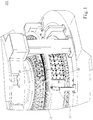
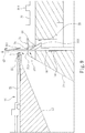
- the circular knitting machine knitting structure is disposed corresponding to a gap 11 of a circular knitting machine 100.
- the gap 11 is defined by a dial 12 and a work drum 13 of the circular knitting machine 100, and the gap 11 is a place where a fabric is knitted and formed by the circular knitting machine 100.
- the circular knitting machine knitting structure mainly includes a first knitting group 20 and a second knitting group 30.
- the first knitting group 20 is able to be disposed on the dial 12 and includes a plurality of knitting bearded needles 21 disposed in a spacing manner with same forms.
- Each of the plurality of knitting bearded needles 21 is provided with a first needle latch 211.
- the plurality of knitting bearded needles 21 are respectively driven by a needle cam (not shown in the figures) to action independently. That is, each of the plurality of knitting bearded needles 21 comprises a first knitting stroke 40 displacing towards the gap 11, as shown in Fig. 6 .
- the second knitting group 30 is able to be disposed on the work drum 13 and includes a plurality of intarsia sinkers 31 and 32 disposed in a spacing manner, two intarsia bearded needles 34 and 35 disposed between any two intarsia sinkers 31 and 32 adjacent to thereof, and a shearing bearded needle 36 disposed between the two intarsia bearded needles 34 and 35.
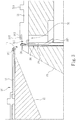
- the shearing bearded needle 36 of the present invention includes a first yarn hooking section 362 facing the gap 11 and comprising a second needle latch 361, a yarn trimming section 364 extending from the first yarn hooking section 362 to form a trimmer 363, and a first control section 366 extending from the yarn trimming section 364 to form at least one first butt 365.
- the trimmer 363 faces the gap 11.
- the trimmer 363 of the present invention and the second needle latch 361 are not closely disposed, but are disposed in a spacing manner, so that the shearing bearded needle 36 also comprises a knitting action in addition to a shearing function.
- the first butt 365 of the shearing bearded needle 36 is pushed by a control cam (not shown in the figures) to displace towards the gap 11.
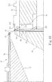
- the shearing bearded needle 36 comprises a second knitting stroke 41 (as shown in Fig. 7 ) displacing towards the gap 11 to pull a yarn via the first yarn hooking section 362, and a yarn trimming stroke 42 (as shown in Fig. 9 ) displacing towards the gap 11 to cut the yarn hooked by one of the intarsia bearded needles 34 (35) via the trimmer 363.
- the shearing bearded needle 36 carries out the second knitting stroke 41 or the yarn trimming stroke 42 based on a displaced degree that pushed by the control cam.
- each of the intarsia bearded needles 34 (35) of the prevent invention comprises a second yarn hooking section 341 (351) facing the gap 11, a connecting section 342 (352) extending from the second yarn hooking section 341 (351) and a second control section 344 (354) extending from the connecting section 342 (352) to form at least one second butt 343 (353).
- the second yarn hooking section 341 (351) of each of the intarsia bearded needles 34 (35) and the first yarn hooking section 362 are located on different extending lines. Referring to Fig.
- each of the intarsia bearded needles 34 (35) comprises a yarn hooking stroke 43 for pulling the yarn to displace towards one of the intarsia sinkers 31 (32).
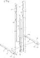
- each of the plurality of intarsia sinkers 31 (32) is staggered with the arrangement directions of the two intarsia bearded needles 34 and 35 as well as the shearing bearded needle 36, as shown in Fig. 3 .
- each of the plurality of intarsia sinkers 31 (32) comprises a yarn hanging part 311 (321) staggered with the yarn hooking stroke 43 and a throat part 312 (322) connected to the yarn hanging part 311 (321).
- each of the plurality of yarn hanging parts 311 (321) is able to be formed by a plane 313 (323) on each of the plurality of intarsia sinkers 31 (32).
- each of the plurality of intarsia sinkers 31 (32) is not pushed by a sinker cam (not shown in the figure)
- each of the plurality of intarsia sinkers 31 (32) allows the yarn hooked by each of the intarsia bearded needles 34 (35) in the yarn hooking stroke 43 to be hung on each of the plurality of yarn hanging parts 311 (321).
- each of the plurality of intarsia sinkers 31 (32) comprises a control butt 314 (324).
- Each control butt 314 (324) is pushed by the sinker cam, so as to allow each of the plurality of intarsia sinkers 31 (32) to comprise a yarn pushing stroke 44 for hanging the yarn thereon to be fed into the shearing bearded needle 36. Further, in the process of the yarn pushing stroke 44, the throat part 312 (322) of each the plurality of intarsia sinkers 31 (32) pushes the yarn hung on one of the plurality of intarsia sinkers 31 (32) to displace towards the shearing bearded needle 36, so that the yarn pushed by the throat part 312 (322) of each of the plurality of intarsia sinkers 31 (32) is fed into the shearing bearded needle 36. In addition, the yarn pushing stroke 44 is parallel to the first knitting stroke 40.
- the circular knitting machine knitting structure of the present invention achieves the circular knitting machine 100 knitting a double-sided cloth 60 wherein comprise a cut-pile fabric is on one side.
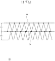
- the double-sided cloth 60 is shown as Fig. 11 , which comprises a first cloth layer 61, a second cloth layer 62, a middle layer 63 for connecting the first cloth layer 61 with the second cloth layer 62, and a pile layer 64 arranged on the second cloth layer 62.
- a knitting process is described below, and a knitting order is shown as Fig. 12 .
- the plurality of knitting bearded needles 21 on the first knitting group 20 knit the first cloth layer 61, and patterns of the first cloth layer 61 is properly adjusted according to an implemented demand.
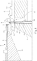
- two different yarns 70 and 71 are respectively fed into one of the intarsia bearded needles 34 and the shearing bearded needle 36.
- One of the intarsia bearded needles 34 operates the yarn hooking stroke 43 to allow one of the yarns 71 fed into one of the intarsia bearded needles 34 to be hung on one of the intarsia sinkers 31.
- one of the intarsia sinkers 31 operates the yarn pushing stroke 44 to allow one of the yarns 71 hung on one of the intarsia sinkers 31 to be fed into the shearing bearded needle 36.
- the shearing bearded needle 36 is controlled to operate the second knitting stroke 41, wherein one of the yarns 70 is fed into the shearing bearded needle 36 by a yarn carrier (not shown in the figures), and the another one of yarns 71 is also fed into the shearing bearded needle 36 by the intarsia sinkers 31, so as to knit the second cloth layer 62.
- one of the yarns 71 hooked by one of the intarsia bearded needles 34 is knitted into a loop when fed into the shearing bearded needle 36.
- the shearing bearded needle 36 is controlled to operate the yarn trimming stroke 42, that is, the displaced degree of the shearing bearded needle 36 equals the trimmer 363 being able to trim one of the yarns 71 hooked by one of the intarsia bearded needles 34, that is, the cut-pile fabric is formed by trimming loops which are formed by one of the yarns 71.
- the pile layer 64 is formed at the place where the cut-pile fabric is located.
- a yarn 72 is fed into the plurality of knitting bearded needles 21 and the shearing bearded needle 36, wherein the plurality of knitting bearded needles 21 and the shearing bearded needle 36 are allowed to interweave with the first cloth layer 61 and the second cloth layer in a half or full stitching manner, as shown in Fig. 10 .
- the yarn 72 forms the middle layer 63, and the double-sided cloth 60 of the present invention is completed. Therefore, the manufacturing cost and the manufacturing time of the double-sided cloth 60 may be reduced.
- the foregoing needle cam, control cam and sinker cam of the present invention are conventional structures on the circular knitting machine 100. Those of ordinary skill in the art can learn about the uses of the cams according to their names, so no more details will be described herein.
Landscapes
- Engineering & Computer Science (AREA)
- Textile Engineering (AREA)
- Knitting Machines (AREA)
- Knitting Of Fabric (AREA)
Priority Applications (1)
| Application Number | Priority Date | Filing Date | Title |
|---|---|---|---|
| EP19167540.4A EP3719190A1 (de) | 2019-04-05 | 2019-04-05 | Rundstrickmaschinenstrickstruktur zum stricken eines doppelseitigen tuchs mit schnittflorgewebe |
Applications Claiming Priority (1)
| Application Number | Priority Date | Filing Date | Title |
|---|---|---|---|
| EP19167540.4A EP3719190A1 (de) | 2019-04-05 | 2019-04-05 | Rundstrickmaschinenstrickstruktur zum stricken eines doppelseitigen tuchs mit schnittflorgewebe |
Publications (1)
| Publication Number | Publication Date |
|---|---|
| EP3719190A1 true EP3719190A1 (de) | 2020-10-07 |
Family
ID=66101925
Family Applications (1)
| Application Number | Title | Priority Date | Filing Date |
|---|---|---|---|
| EP19167540.4A Withdrawn EP3719190A1 (de) | 2019-04-05 | 2019-04-05 | Rundstrickmaschinenstrickstruktur zum stricken eines doppelseitigen tuchs mit schnittflorgewebe |
Country Status (1)
| Country | Link |
|---|---|
| EP (1) | EP3719190A1 (de) |
Citations (7)
| Publication number | Priority date | Publication date | Assignee | Title |
|---|---|---|---|---|
| GB988865A (en) | 1958-02-28 | 1965-04-14 | Alfred Planck | Improvements in or relating to circular knitting machines for the production of plush fabric |
| GB1124858A (en) * | 1965-12-23 | 1968-08-21 | Buck Robert | A needle for weaving and knitting machines |
| GB2062696A (en) * | 1979-11-12 | 1981-05-28 | Nishiki Keori Kk | Pile Fabric Knitting |
| US4409800A (en) | 1978-05-11 | 1983-10-18 | Monarch Knitting Machinery Corp. | Method of and apparatus for knitting cut-pile fabric |
| US4592212A (en) | 1981-12-22 | 1986-06-03 | Schmidt Walter R | Circular knitting machine for the production of cut pile |
| WO2015163587A1 (ko) * | 2014-04-23 | 2015-10-29 | 송유철 | 이중원단 제조방법 및 이중원단 |
| US9890486B2 (en) | 2014-05-19 | 2018-02-13 | Pai Lung Machinery Mill Co., Ltd. | Loop cutting apparatus for circular knitting machines |
-
2019
- 2019-04-05 EP EP19167540.4A patent/EP3719190A1/de not_active Withdrawn
Patent Citations (7)
| Publication number | Priority date | Publication date | Assignee | Title |
|---|---|---|---|---|
| GB988865A (en) | 1958-02-28 | 1965-04-14 | Alfred Planck | Improvements in or relating to circular knitting machines for the production of plush fabric |
| GB1124858A (en) * | 1965-12-23 | 1968-08-21 | Buck Robert | A needle for weaving and knitting machines |
| US4409800A (en) | 1978-05-11 | 1983-10-18 | Monarch Knitting Machinery Corp. | Method of and apparatus for knitting cut-pile fabric |
| GB2062696A (en) * | 1979-11-12 | 1981-05-28 | Nishiki Keori Kk | Pile Fabric Knitting |
| US4592212A (en) | 1981-12-22 | 1986-06-03 | Schmidt Walter R | Circular knitting machine for the production of cut pile |
| WO2015163587A1 (ko) * | 2014-04-23 | 2015-10-29 | 송유철 | 이중원단 제조방법 및 이중원단 |
| US9890486B2 (en) | 2014-05-19 | 2018-02-13 | Pai Lung Machinery Mill Co., Ltd. | Loop cutting apparatus for circular knitting machines |
Similar Documents
| Publication | Publication Date | Title |
|---|---|---|
| CN110760980B (zh) | 一种双面结构纬编割绒针织物及其编织方法 | |
| EP3081680B1 (de) | Verfahren zum stricken eines einzelnen jacquard-maschenmusters und damit hergestellte zusammengesetzte maschenware | |
| CN110387636B (zh) | 用于制造金银丝针织物的针织横机和方法 | |
| JP6628920B1 (ja) | 丸編機を用いてカットパイルを有する両面布地を編成する方法 | |
| EP2568066B1 (de) | Strickanfangsverfahren für Maschenware | |
| JP6656449B1 (ja) | カットパイルを有する両面布地を編成する丸編機の編成構造 | |
| EP3719190A1 (de) | Rundstrickmaschinenstrickstruktur zum stricken eines doppelseitigen tuchs mit schnittflorgewebe | |
| KR102105581B1 (ko) | 커트파일 직물을 포함하는 양면천을 편성하기 위한 환편기 편성 구조 | |
| US20200318268A1 (en) | Circular knitting machine knitting structure for knitting a double-sided cloth comprising a cut-pile fabric | |
| US2541499A (en) | Composite yarn, fabric made therefrom, and method of making the same | |
| US4554801A (en) | Pile fabric method and apparatus | |
| CN111719223A (zh) | 以圆编机针织具有割圈绒双面布的方法 | |
| CN111719227A (zh) | 用于编织具有割圈绒双面布的圆编机针织结构 | |
| KR101031805B1 (ko) | 환편기 편침을 교대 반복 작동시켜 조직이 조밀한 파일원단을 직조하는 방법 | |
| EP2546399B1 (de) | Verfahren für Startstrickreihen einer Maschenware sowie Maschenware | |
| KR102129520B1 (ko) | 환편기로 커트파일 직물을 포함하는 양면천을 편성하는 방법 | |
| JP7478299B1 (ja) | 丸編機及び丸編機で両面ロングパイル編み物を編む方法 | |
| KR100530830B1 (ko) | 화섬 필라멘트사 또는 금속사를 파일사로 사용한컷파일지의 제조방법 | |
| EP3719189A1 (de) | Verfahren zum stricken eines doppelseitigen tuchs mit schnittflorgeweben mit einer rundstrickmaschine | |
| TWI694188B (zh) | 用於編織具割圈絨雙面布的圓編機針織結構 | |
| CN216947395U (zh) | 一种圆编机 | |
| EP0387094A3 (de) | Verfahren zur Herstellung eines Doppelfutter-Gestrickes mittels Rundstrickmaschine | |
| US6212912B1 (en) | Method for the manufacture of designed knitwear on circular stocking knitting and knitting machines | |
| US2077033A (en) | Knitted fabric | |
| DE60011280D1 (de) | Verfahren zur herstellung einer schuss-strickware mit am rückseitemaschen geformten schnittpol, nach diesem verfahren arbeitende strickmaschine und damit erhaltene strickware |
Legal Events
| Date | Code | Title | Description |
|---|---|---|---|
| PUAI | Public reference made under article 153(3) epc to a published international application that has entered the european phase |
Free format text: ORIGINAL CODE: 0009012 |
|
| STAA | Information on the status of an ep patent application or granted ep patent |
Free format text: STATUS: THE APPLICATION HAS BEEN PUBLISHED |
|
| AK | Designated contracting states |
Kind code of ref document: A1 Designated state(s): AL AT BE BG CH CY CZ DE DK EE ES FI FR GB GR HR HU IE IS IT LI LT LU LV MC MK MT NL NO PL PT RO RS SE SI SK SM TR |
|
| AX | Request for extension of the european patent |
Extension state: BA ME |
|
| STAA | Information on the status of an ep patent application or granted ep patent |
Free format text: STATUS: THE APPLICATION IS DEEMED TO BE WITHDRAWN |
|
| 18D | Application deemed to be withdrawn |
Effective date: 20210408 |