EP3719187A1 - Device for forming a shed and jacquard loom equipped with such a device - Google Patents
Device for forming a shed and jacquard loom equipped with such a device Download PDFInfo
- Publication number
- EP3719187A1 EP3719187A1 EP20166942.1A EP20166942A EP3719187A1 EP 3719187 A1 EP3719187 A1 EP 3719187A1 EP 20166942 A EP20166942 A EP 20166942A EP 3719187 A1 EP3719187 A1 EP 3719187A1
- Authority
- EP
- European Patent Office
- Prior art keywords
- oscillating
- oscillating shaft
- forming device
- housing
- shed forming
- Prior art date
- Legal status (The legal status is an assumption and is not a legal conclusion. Google has not performed a legal analysis and makes no representation as to the accuracy of the status listed.)
- Granted
Links
- 230000015572 biosynthetic process Effects 0.000 description 5
- BASFCYQUMIYNBI-UHFFFAOYSA-N platinum Chemical compound [Pt] BASFCYQUMIYNBI-UHFFFAOYSA-N 0.000 description 3
- 229910001018 Cast iron Inorganic materials 0.000 description 1
- 240000008042 Zea mays Species 0.000 description 1
- 210000000078 claw Anatomy 0.000 description 1
- 229940082150 encore Drugs 0.000 description 1
- 235000021183 entrée Nutrition 0.000 description 1
- 238000005461 lubrication Methods 0.000 description 1
- 238000003754 machining Methods 0.000 description 1
- 239000002184 metal Substances 0.000 description 1
- 229910052751 metal Inorganic materials 0.000 description 1
- 238000000465 moulding Methods 0.000 description 1
- 230000000284 resting effect Effects 0.000 description 1
- 238000005096 rolling process Methods 0.000 description 1
- 238000009941 weaving Methods 0.000 description 1
Images


Classifications
-
- D—TEXTILES; PAPER
- D03—WEAVING
- D03C—SHEDDING MECHANISMS; PATTERN CARDS OR CHAINS; PUNCHING OF CARDS; DESIGNING PATTERNS
- D03C3/00—Jacquards
- D03C3/24—Features common to jacquards of different types
- D03C3/32—Jacquard driving mechanisms
- D03C3/36—Griffe operating mechanisms
-
- D—TEXTILES; PAPER
- D03—WEAVING
- D03C—SHEDDING MECHANISMS; PATTERN CARDS OR CHAINS; PUNCHING OF CARDS; DESIGNING PATTERNS
- D03C3/00—Jacquards
- D03C3/24—Features common to jacquards of different types
- D03C3/26—General arrangements of jacquards, or disposition in relation to loom
Definitions
- the present invention relates to a shed forming device for a Jacquard type loom.
- Jacquard mechanical comprising two series of longitudinal blades or knives driven in an alternating vertical movement in phase opposition. , on which can bear the hooks of devices for selecting the movement of collars constituting the upper ends of a Jacquard harness.
- CN-U-201915195 discloses such a Jacquard mechanism which comprises two oscillating axes arranged one above the other and articulated in two plates, between which extend two series of knives or blades as well as the two axes.
- the two axes are equipped with tilting levers on each of which is articulated a connecting rod which supports a drive bar of a series of blades, such a bar sometimes being called an "oblique bar”.
- An input shaft drives the two oscillating axes by means of two eccentrics which each actuate a control rod connected to a crank fixed to one of the oscillating axes.
- Such a kinematics has the advantage of simplicity. However, it lacks rigidity to be able to ensure correct operation at the high speeds required in modern weaving workshops, in particular greater than 1000 picks / minute. Indeed, the oscillating axes which are each connected to a crank are subjected to high torques which induce deformations liable to slow down, or even block, the operation of the Jacquard mechanism.
- the invention more particularly intends to remedy by proposing a new device for forming the shed for a Jacquard type loom which has a simple structure and which can operate at high speeds in a reliable manner.
- the two eccentrics, the two control rods and the two cranks are contained in a casing which supports at least one additional articulation bearing of the first oscillating shaft.
- the first oscillating shaft which has the greatest length beyond the first plate relative to the volume defined between the two plates, because it is connected to the first connecting rod which is the most remote from this first plate, does not extend overhanging but between the bearings supported respectively by the first plate and by the casing. This limits the risks of deformation of this first oscillating shaft during operation of the Jacquard mechanism and allows the latter to work at high speeds in a reliable manner.
- the invention relates to a Jacquard type loom which comprises, inter alia, a shed forming device as mentioned above.
- Such a loom can operate at high speed reliably without being limited in this by the shed forming device.
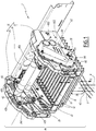
- the loom M represented very schematically on figure 1 is of the Jacquard loom type and comprises a shed forming device, 2, also called a “Jacquard mechanical”, intended to move alternately, with a vertical movement represented by the double arrow F1 at the bottom.
- heddles 4 provided with eyelets 42 for passing the warp son 6.
- the various heddles are supported by the cords of a Jacquard harness 8, the upper ends of which are connected to the collars of selection devices provided with hooks 10 resting on two series of knives 12 and 14 driven in an alternating vertical movement in opposition to phase represented by the double arrow F2 at the figure 1 .
- the two series of knives 12 and 14 are nested one inside the other, in the sense that, except at the level of the longitudinal edges of the shed forming device 2, a knife 12 is arranged between two knives 14 and vice versa.
- the shed forming device 2 comprises a frame 16 which includes two longitudinal cross members 18 and 20 extending parallel to a longitudinal axis X2 of the shedding forming device 2.
- the longitudinal cross member 20 is omitted. to the figure 1
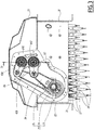
- the longitudinal cross member 18 is omitted at the figure 2 .
- the two series of knives 12 and 14 extend between the longitudinal crossbars 18 and 20, parallel to the axis X2.
- the frame 16 also comprises a first frame plate 22 and a second frame plate 24 arranged between the longitudinal cross members 18 and 20 and which each extend perpendicular to the axis X2.
- the two series of knives 12 and 14 are arranged, along the axis X2, in a volume V2 of the shed forming device 2 located between the plates 22 and 24.
- Each frame plate 22 or 24 is made by molding and machining metal, preferably cast iron, and includes stiffening ribs, some of which are visible on the sides. figures 1 and 2 with the reference 241 for the plate 24, the stiffening ribs of the plate 22 being hidden from the figure 1 . For clarity of the drawing, plate 22 is omitted at the figure 2 .
- Each knife 12 or 14 of a series of knives is guided linearly in its vertical movement according to the double arrow F2 and connected, at each of its ends, to a rod 26 suspended from a drive bar, also called "oblique bar". . More precisely, each knife of a series of knives 12 or 14 is suspended by two links 26 from two drive bars, namely a first drive bar arranged in the vicinity of the plate 22 and a second drive bar arranged in the vicinity of plate 24.
- the four training bars are visible at figure 2 and include a first drive bar 30 and a second drive bar 32 disposed adjacent to platen 22, and a third drive bar 34 and fourth drive bar 36 disposed adjacent to platen 24
- the four drive bars 30 to 36 are each respectively articulated on a guide arm 31, 33, 35 or 37, itself articulated on the frame 16, at or near the longitudinal cross member 18.
- Each drive bar consists of two flanges, like the drive bar 30 of which 302 and 304 are noted the flanges.
- the shed forming device 2 also comprises an upper oscillating shaft 40 and a lower oscillating shaft 42 arranged one above the other and which extend parallel to the axis X2.
- the upper oscillating shaft 40 comprises a tube 402 whose diameter is, in the example, equal to 120 mm.
- the diameter of the tube 402 is between 80 and 160 mm, preferably between 100 and 140 mm, more preferably of the order of 120 mm, which gives it good torsional rigidity.
- the tube 402 is fixed to a rocker 404 which also belongs to the shaft 40 and which defines two rocking levers 405 and 406.
- the lower oscillating shaft 42 includes a central tube 422 and two rockers 424 which each define two rocking levers 425 and 426.
- the diameter of the tube 422 is the same as that of the tube 402.
- the longitudinal axes of the oscillating shafts 40 and 42 are denoted respectively X40 and X42. These axes are parallel to the longitudinal axis X2.
- the rockers 404 and 424 are respectively secured to the tubes 402 and 422 by screws 43 parallel to the axes X40 and X42.
- the rocking levers 405 and 406 of the rocker 404 are respectively connected to the drive bar 30 and to the drive bar 32 by means of connecting rods 50.
- the rocking levers 405 and 406 of the latch 404 are respectively connected by connecting rods 50 to the drive bar 34 and to the drive bar 36.
- the rocking levers 425 and 426 of the rocker 424 are respectively connected to the drive bar 30 and to the drive bar 32 by means of connecting rods 52.
- the rocking levers 425 and 426 of the rocker 424 are respectively connected by connecting rods 52 to the drive bar 34 and to the drive bar 36.
- the position of the articulation points of the connecting rods 50 and 52 on the rocking levers 405, 406, 425 and 426 is adjustable, in notches in an arc of a circle provided on these rocking levers.
- Bearings are respectively provided in the plates 22 and 24 to support the oscillating shafts 40 and 42 in their alternating rotational movement around their axes X40 and X42.
- the plates 22 and 24 constitute support plates for the oscillating shafts 40 and 42.
- bearings 220 and 240 are respectively provided in the plates 22 and 24 to support the upper oscillating shaft 40.
- the bearing 220 is through, while the bearing 240 is blind.
- each of the bearings 220 and 240 is equipped with a bearing 620, 640 respectively.
- the parts of the shaft 40 engaged in the bearings 620 and 640 are axial ends 404A of the rockers 404 opposite the tube 402.
- the parts Rockers 404 of the shaft 40 are articulated in the plates 22 and 24.
- the plates 22 and 24 carry two bearings 222 and 242 in which the rockers 424 of the lower oscillating shaft 42 are articulated, with the interposition of two bearings 622 and 642.
- the bearing 222 is through, while the bearing 242 is one-eyed.
- it is the axial ends 424A of the rockers 424A opposite the tube 422 which are articulated in the bearings 622 and 642.
- Bearings 620, 622, 640 and 642 are needle roller bearings. As a variant, it could be ball bearings or any other type of bearing.
- the two oscillating shafts 40 and 42 are driven in rotation, respectively around the axes X40 and X42 by a drive assembly 70 disposed on the side of the plate 22 opposite the knives 12 and 14, that is to say the outside of volume V2.
- the movement or control of the oscillating shafts 40 and 42 thus comes from the side of the plate 22 which can be qualified as "control plate”.
- the drive assembly 70 comprises an input shaft 72 driven by a continuous rotational movement represented by the arrow F3 as well as a first eccentric 74 and a second eccentric 76.
- the second eccentric 76 is located closer to plate 22 than the first eccentric 74.
- the first eccentric 74 drives a first control rod 84 which is coupled to a first crank 428 which forms part of the oscillating shaft 42 and which is mounted at the end of the rocker 424 articulated in the bearing 222.
- the second eccentric 76 drives a second control rod 86 coupled to another crank 408 which belongs to the upper oscillating shaft 40 and which is mounted at the end of the rocker 404 articulated in the bearing 220.
- cranks 408 and 428 are respectively mounted on the rockers 404 and 424 which cross the plate 22, on the side of these rockers opposite the tubes 402 and 422. Screws 45, parallel to the axes X40 and X42, are used to secure the parts together. 404 and 408 of the swing shaft 40 and the parts 424 and 428 of the swing shaft 42.
- the first control rod 84 is further away, along the axis X2, from the plate 22 than the second control rod 86.
- the second eccentric 76 and the second rod 86 can be qualified as proximal eccentric and proximal link, while the first eccentric 74 and the second link 84 can be described as distal eccentric and distal link.
- a casing 90 is mounted on the plate 22, on the side of this plate opposite the tubes 402 and 422, that is to say opposite the volume V2.
- the housing 90 is immobilized on the plate 22 by means of screws 47.
- Two bearings 900 and 902 are respectively provided in the housing 90 to support the ends of the cranks 408 and 428 opposite to the rockers 404 and 424 on which they are respectively fixed.
- Two bearings 920 and 922 are respectively arranged in the bearings 900 and 902 to support the cranks 408 and 428 in the bearings 900 and 902, with the possibility of rotation, respectively around the axes X40 and X42. More precisely, the ends of the cranks 408 and 428 opposite the rockers 404 and 424 are mounted in the inner rings of the bearings 920 and 922, while the outer rings of these bearings are immobilized in the bearings 900 and 902.
- the bearings 900 and 902 are formed by caps mounted in corresponding housings 904 and 906 formed in the bottom wall 92 of the casing 90 which is parallel to the plate 22.
- Each cap 900, respectively 902 is formed of a ring 900A, respectively 902A, and a cover 900B, respectively 902B.
- the bearings 900 and 902 are therefore blind.
- the mounting of the bearings or caps 900 and 902 in the housings 904 and 906 of the housing 90 makes it possible to adjust the position of the bearings 920 and 922 relative to the housing 90 and to solve a possible problem of hyper-droop of the oscillating shafts 40 and 42, due to the establishment of three bearings along the length of each of these shafts.
- the rings 900A and 902A are mounted with play in the housings 904 and 906 and are positioned radially according to the real positions of the bearings of the shafts 40 and 42 in the plates 22 and 24 and the real geometry of the shafts 40 and 42. A once positioned, they are tightened by screws parallel to the axes X40 and X42 on the bottom wall 92 of the casing 90.
- the caps 900 and 902 are therefore adjustable radially with respect to the axes X40 and X42.
- Bearings 920 and 922 may be the same type or a different type from bearings 620, 640, 622 and 642.
- bearings 920 and 922 are roller bearings.
- the oscillating shafts 40 and 42 are supported at their two ends, both at the level of the plate 24 and at the level of the casing 90.
- the cranks 408 and 428 are not cantilevered beyond the control plate 22 relative to the zone located between the two plates 22 and 24, which avoids the risk of deformation of the shafts 40 and 42 during operation of the device for forming the shed 2, especially for the lower oscillating shaft 42 which would be the most subject to deformations in the absence of the bearing 902 because its crank 428 is the furthest from the control plate 22
- This shed forming device 2 can therefore operate at high speed, in particular at speeds greater than 1000 picks / minute, reliably.
- the housing 90 contains the two eccentrics 74 and 76, the two control rods 84 and 86 and the two cranks 408 and 428.
- the contour of the housing 90 in contact with the plate 22 is continuous and provided with a seal 93
- the housing 90 supports a bearing 94 of the input shaft 72 which is also provided with a seal.
- the housing 90 defines a closed volume suitable for receiving oil which can provide lubrication for the bearings 220, 222, 900, 902 and the bearing 94 of the input shaft 72.
- a single bearing 902 is provided in the housing 90 to support the crank 428, while the crank 408 extends in a cantilever manner, beyond the bearing 220 relative to the control plate. 22.
- the oscillating shaft 42 which is driven by the first distal control rod 84 is supported by three bearings 222, 242 and 902.
- Each of these bearings is equipped with a bearing 622, 642 or more. 922.
- This embodiment is suitable for small-format looms, for example whose harness comprises less than 2688 collars, for which it is conceivable to support by means of only two bearings 220 and 240 the upper oscillating shaft 40 driven by the second proximal link 86, insofar as the torque produced by the deformation force applied by this link on the crank 408, relative to the bearing 220 of the plate 22, is relatively limited, in all cases more limited than the torque produced by the deformation force applied by the first distal link 84 on the crank 428 relative to the bearing 242.
- the invention is shown in the case where the oscillating shaft driven by the first distal link 84 is the lower oscillating shaft 42. It is however applicable to the reverse case where it is the upper oscillating shaft 40 which is driven by the. first distal connecting rod. In this case, if a single bearing is provided in the housing 90 as in the second embodiment, this bearing supports the upper oscillating shaft 40.
- the invention is not limited to the case where the two series of knives 12 and 14 are connected to the drive bars by rods such as rods 26.
- the invention can be applied in the case where both series of knives are each grouped together on a claw frame suspended from two drive bars.
- some or all of the bearings 220, 222, 240, 242, 900 and 902 may be plain bearings, without rolling.
- the parts 404, 408, 424 and 428 of the shafts 40 and 42 are then directly articulated in these bearings.
- the caps are omitted and the bearings 900 and / or 902 are made directly in the wall 92 of the casing 90.
Landscapes
- Engineering & Computer Science (AREA)
- Textile Engineering (AREA)
- Looms (AREA)
Abstract
Dispositif de formation de la foule (2) pour métier à tisser de type Jacquard comprenant deux séries de couteaux, un arbre oscillant supérieur (40) et un arbre oscillant inférieur (42) avec deux leviers basculants reliés chacun à une barre d'entraînement par une bielle de liaison, ainsi que deux platines de châssis (22, 24), entre lesquelles s'étendent les deux séries de couteaux et les arbres oscillants et qui sont pourvues de paliers (220, 222, 240, 242) d'articulation des arbres oscillants, un arbre d'entrée, équipé d'un premier excentrique et d'un deuxième excentrique disposés au voisinage d'une première platine (22), le premier excentrique entraîne une première bielle de commande et le deuxième excentrique entraîne une deuxième bielle de commande. La première bielle de commande est plus éloignée de la première platine que la deuxième bielle de commande. Les deux excentriques, les deux bielles de commande et les deux manivelles (408, 428) sont contenus dans un carter (90) qui supporte au moins un palier (902) d'articulation supplémentaire du premier arbre oscillant (42).Shed forming device (2) for Jacquard type loom comprising two sets of knives, an upper oscillating shaft (40) and a lower oscillating shaft (42) with two tilting levers each connected to a drive bar by a connecting rod, as well as two frame plates (22, 24), between which extend the two series of knives and the oscillating shafts and which are provided with bearings (220, 222, 240, 242) of articulation of the oscillating shafts, an input shaft, equipped with a first eccentric and a second eccentric arranged in the vicinity of a first plate (22), the first eccentric drives a first control rod and the second eccentric drives a second rod control. The first control rod is further from the first plate than the second control rod. The two eccentrics, the two control rods and the two cranks (408, 428) are contained in a housing (90) which supports at least one additional articulation bearing (902) of the first oscillating shaft (42).
Description
La présente invention a trait à un dispositif de formation de la foule pour métier à tisser de type Jacquard.The present invention relates to a shed forming device for a Jacquard type loom.
Dans le domaine des métiers à tisser de type Jacquard, il est connu d'utiliser un dispositif de formation de la foule, parfois dénommé « mécanique Jacquard » comprenant deux séries de lames ou couteaux longitudinaux animés d'un mouvement vertical alternatif en opposition de phase, sur lesquels peuvent venir en appui les crochets de dispositifs de sélection du mouvement de collets constituant les extrémités supérieures d'un harnais Jacquard.In the field of Jacquard type looms, it is known to use a shed forming device, sometimes referred to as a “Jacquard mechanical” comprising two series of longitudinal blades or knives driven in an alternating vertical movement in phase opposition. , on which can bear the hooks of devices for selecting the movement of collars constituting the upper ends of a Jacquard harness.
Une telle cinématique présente l'avantage de la simplicité. Toutefois, elle manque de rigidité pour pouvoir assurer un fonctionnement correct à des vitesses élevées requises dans les ateliers de tissage modernes, notamment supérieures à 1000 duites/minute. En effet, les axes oscillants qui sont connectés chacun à une manivelle sont soumis à des couples importants qui induisent des déformations susceptibles de ralentir, voire de bloquer, le fonctionnement de la mécanique Jacquard.Such a kinematics has the advantage of simplicity. However, it lacks rigidity to be able to ensure correct operation at the high speeds required in modern weaving workshops, in particular greater than 1000 picks / minute. Indeed, the oscillating axes which are each connected to a crank are subjected to high torques which induce deformations liable to slow down, or even block, the operation of the Jacquard mechanism.
C'est à ces inconvénients qu'entend plus particulièrement remédier l'invention en proposant un nouveau dispositif de formation de la foule pour métier à tisser de type Jacquard qui présente une structure simple et qui peut fonctionner à des vitesses élevées, de façon fiable.It is these drawbacks that the invention more particularly intends to remedy by proposing a new device for forming the shed for a Jacquard type loom which has a simple structure and which can operate at high speeds in a reliable manner.
A cet effet, l'invention concerne un dispositif de formation de la foule pour métier à tisser de type Jacquard, comprenant :
- deux séries de couteaux longitudinaux s'étendant parallèlement à un axe longitudinal du dispositif de formation de la foule, animés d'un mouvement vertical alternatif en opposition de phase et reliés, à chacune de leurs extrémités, à une barre d'entraînement ;
- un arbre oscillant supérieur et un arbre oscillant inférieur qui s'étendent l'un au-dessus de l'autre et qui sont respectivement pourvus, à chacune de leurs extrémités, de deux leviers basculants reliés chacun à une barre d'entraînement par une bielle de liaison ;
- deux platines de châssis, entre lesquelles s'étendent les deux séries de couteaux et les arbres oscillants et qui sont pourvues de paliers d'articulation des arbres oscillants ;
- un arbre d'entrée animé d'un mouvement de rotation continue et équipé d'un premier excentrique et d'un deuxième excentrique disposés au voisinage d'une première platine, parmi les deux platines de châssis, à l'extérieur d'un volume défini entre ces platines, le premier excentrique entraînant une première bielle de commande attelée à une première manivelle appartenant à un premier arbre oscillant, parmi les deux arbres oscillants, le deuxième excentrique entraînant une deuxième bielle de commande attelée à une deuxième manivelle appartenant au deuxième arbre oscillant, parmi les deux arbres oscillants, et la première bielle de commande étant plus éloignée de la première platine, le long de l'axe longitudinal, que la deuxième bielle de commande.
- two series of longitudinal knives extending parallel to a longitudinal axis of the shed forming device, driven by a movement vertical alternating in phase opposition and connected at each of their ends to a drive bar;
- an upper oscillating shaft and a lower oscillating shaft which extend one above the other and which are respectively provided, at each of their ends, with two tilting levers each connected to a drive bar by a connecting rod link ;
- two chassis plates, between which extend the two series of knives and the oscillating shafts and which are provided with articulation bearings of the oscillating shafts;
- an input shaft driven by a continuous rotational movement and equipped with a first eccentric and a second eccentric arranged in the vicinity of a first plate, among the two chassis plates, outside a volume defined between these plates, the first eccentric driving a first control rod coupled to a first crank belonging to a first oscillating shaft, from among the two oscillating shafts, the second eccentric driving a second control rod coupled to a second crank belonging to the second shaft oscillating, among the two oscillating shafts, and the first control rod being further from the first plate, along the longitudinal axis, than the second control rod.
Conformément à l'invention, les deux excentriques, les deux bielles de commande et les deux manivelles sont contenus dans un carter qui supporte au moins un palier d'articulation supplémentaire du premier arbre oscillant.According to the invention, the two eccentrics, the two control rods and the two cranks are contained in a casing which supports at least one additional articulation bearing of the first oscillating shaft.
Grâce à l'invention, le premier arbre oscillant, qui présente la longueur la plus importante au-delà de la première platine par rapport au volume défini entre les deux platines, du fait qu'il est relié à la première bielle qui est la plus éloignée de cette première platine, ne s'étend pas en porte-à-faux mais entre les paliers supportés respectivement par la première platine et par le carter. Ceci limite les risques de déformation de ce premier arbre oscillant lors du fonctionnement de la mécanique Jacquard et permet à celle-ci de travailler à des vitesses élevées, de façon fiable.Thanks to the invention, the first oscillating shaft, which has the greatest length beyond the first plate relative to the volume defined between the two plates, because it is connected to the first connecting rod which is the most remote from this first plate, does not extend overhanging but between the bearings supported respectively by the first plate and by the casing. This limits the risks of deformation of this first oscillating shaft during operation of the Jacquard mechanism and allows the latter to work at high speeds in a reliable manner.
Selon des aspects avantageux mais non obligatoires de l'invention, un tel dispositif de formation de la foule peut incorporer une ou plusieurs des caractéristiques suivantes, prises selon toute combinaison techniquement admissible :
- Le carter supporte, en outre, un palier d'articulation supplémentaire du deuxième arbre oscillant.
- Le premier arbre oscillant est l'arbre oscillant inférieur.
- En variante, le premier arbre oscillant est l'arbre oscillant supérieur.
- Chaque arbre oscillant comprend un tube creux fixé, à chacune de ses extrémités, sur une bascule qui inclut deux leviers basculants et chaque bascule est articulée dans un palier de l'une des platines de châssis.
- Le diamètre du tube creux d'un arbre oscillant est compris entre 80 et 160 mm, de préférence entre 100 et 140 mm, de préférence encore de l'ordre de 120 mm.
- La première manivelle est fixée sur une bascule du premier arbre oscillant et articulée dans le palier supporté par le carter.
- Chaque palier d'articulation supporté par le carter est équipé d'un roulement dans lequel est introduite une partie de l'un des arbres oscillants.
- Chaque palier d'articulation supporté par le carter est formé par un chapeau ajustable radialement par rapport à l'axe de l'arbre oscillant, monté dans un logement d'une paroi du carter et serré sur la paroi du carter.
- The housing further supports an additional articulation bearing of the second oscillating shaft.
- The first oscillating shaft is the lower oscillating shaft.
- Alternatively, the first oscillating shaft is the upper oscillating shaft.
- Each oscillating shaft comprises a hollow tube fixed, at each of its ends, on a rocker which includes two rocking levers and each rocker is articulated in a bearing of one of the frame plates.
- The diameter of the hollow tube of an oscillating shaft is between 80 and 160 mm, preferably between 100 and 140 mm, more preferably of the order of 120 mm.
- The first crank is fixed to a rocker of the first oscillating shaft and articulated in the bearing supported by the housing.
- Each articulation bearing supported by the housing is equipped with a bearing into which a part of one of the oscillating shafts is inserted.
- Each articulation bearing supported by the housing is formed by an adjustable cap radially relative to the axis of the oscillating shaft, mounted in a housing in a wall of the housing and clamped to the wall of the housing.
Selon un autre aspect, l'invention concerne un métier à tisser de type Jacquard qui comprend, entre autres, un dispositif de formation de la foule tel que mentionné ci-dessus.According to another aspect, the invention relates to a Jacquard type loom which comprises, inter alia, a shed forming device as mentioned above.
Un tel métier à tisser peut fonctionner à vitesse élevée, de façon fiable, sans être limité en cela par le dispositif de formation de la foule.Such a loom can operate at high speed reliably without being limited in this by the shed forming device.
L'invention sera mieux comprise et d'autres avantages de celle-ci apparaîtront plus clairement à la lumière de la description qui va suivre, de deux modes de réalisation d'un dispositif de formation de la foule et d'un métier à tisser conformes à son principe, donnée uniquement à titre d'exemple et faite en référence aux dessins annexés, dans lesquels :
- [
Fig 1 ] lafigure 1 est une vue en perspective d'un métier à tisser conforme à l'invention incorporant un dispositif de formation de la foule conforme à l'invention ; - [
Fig 2 ] lafigure 2 est une vue en perspective, selon un autre angle, du dispositif de formation de la foule conforme à l'invention représenté à lafigure 1 , certaines parties de ce dispositif étant omises pour la clarté du dessin ; - [
Fig 3 ] lafigure 3 est une vue d'extrémité du dispositif de formation de la foule de lafigure 2 dans laquelle une platine omise à lafigure 2 est représentée, mais pas un carter omis à lafigure 2 ; - [
Fig 4 ] lafigure 4 est une coupe partielle selon la ligne IV-IV à lafigure 3 , le carter étant en place, et - [
Fig 5 ] lafigure 5 est une coupe partielle analogue à lafigure 4 pour un dispositif de formation de la foule conforme à un deuxième mode de réalisation de l'invention.
- [
Fig 1 ] thefigure 1 is a perspective view of a loom according to the invention incorporating a shed forming device according to the invention; - [
Fig 2 ] thefigure 2 is a perspective view, from another angle, of the shed forming device according to the invention shown infigure 1 , certain parts of this device being omitted for clarity of the drawing; - [
Fig 3 ] thefigure 3 is an end view of the shed forming device of thefigure 2 in which a plate omitted at thefigure 2 is shown, but not an omitted casingfigure 2 ; - [
Fig 4 ] thefigure 4 is a partial cut along line IV-IV at thefigure 3 with the housing in place, and - [
Fig 5 ] thefigure 5 is a partial section similar to thefigure 4 for a shed forming device according to a second embodiment of the invention.
Le métier à tisser M représenté très schématiquement à la
Les différentes lisses sont supportées par les cordons d'un harnais Jacquard 8 dont les extrémités supérieures sont connectées aux collets de dispositifs de sélection pourvus de crochets 10 en appui sur deux séries de couteaux 12 et 14 animés d'un mouvement vertical alternatif en opposition de phase représenté par la double flèche F2 à la
Le dispositif de formation de la foule 2 comprend un châssis 16 qui inclut deux traverses longitudinales 18 et 20 s'étendant parallèlement à un axe longitudinal X2 du dispositif de formation de la foule 2. Pour la clarté du dessin, la traverse longitudinale 20 est omise à la
Les deux séries de couteaux 12 et 14 s'étendent entre les traverses longitudinales 18 et 20, parallèlement à l'axe X2.The two series of
Le châssis 16 comprend également une première platine de châssis 22 et une deuxième platine de châssis 24 disposées entre les traverses longitudinales 18 et 20 et qui s'étendent chacune perpendiculairement à l'axe X2. Les deux séries de couteaux 12 et 14 sont disposées, le long de l'axe X2, dans un volume V2 du dispositif de formation de la foule 2 situé entre les platines 22 et 24.The
Chaque platine de châssis 22 ou 24 est réalisée par moulage et usinage de métal, de préférence de la fonte, et comprend des nervures de rigidification, dont certaines sont visibles sur les
Chaque couteau 12 ou 14 d'une série de couteaux est guidé linéairement dans son mouvement vertical selon la double flèche F2 et relié, à chacune de ses extrémités, à une biellette 26 suspendue à une barre d'entraînement, également dénommée « barre oblique ». Plus précisément, chaque couteau d'une série de couteaux 12 ou 14 est suspendu par deux biellettes 26 à deux barres d'entraînement, à savoir une première barre d'entraînement disposée au voisinage de la platine 22 et une deuxième barre d'entraînement disposée au voisinage de la platine 24.Each
Les quatre barres d'entraînement sont visibles à la
Chaque barre d'entraînement est constituée de deux flasques, comme la barre d'entraînement 30 dont on note 302 et 304 les flasques.Each drive bar consists of two flanges, like the
Le dispositif de formation de la foule 2 comprend également un arbre oscillant supérieur 40 et un arbre oscillant inférieur 42 disposés l'un au-dessus de l'autre et qui s'étendent parallèlement à l'axe X2.The
L'arbre oscillant supérieur 40 comprend un tube 402 dont le diamètre est, dans l'exemple, égal à 120 mm. En pratique, le diamètre du tube 402 est compris entre 80 et 160 mm, de préférence entre 100 et 140 mm, de préférence encore de l'ordre de 120 mm, ce qui lui confère une bonne rigidité en torsion.The upper oscillating
A chacune de ses extrémités, le tube 402 est fixé à une bascule 404 qui appartient également à l'arbre 40 et qui définit deux leviers basculants 405 et 406.At each of its ends, the
De la même façon, l'arbre oscillant inférieur 42 comprend un tube central 422 et deux bascules 424 qui définissent chacune deux leviers basculants 425 et 426. Le diamètre du tube 422 est le même que celui du tube 402.Likewise, the lower oscillating
On note respectivement X40 et X42 les axes longitudinaux des arbres oscillants 40 et 42. Ces axes sont parallèles à l'axe longitudinal X2.The longitudinal axes of the
Les bascules 404 et 424 sont respectivement solidarisées aux tubes 402 et 422 par des vis 43 parallèles aux axes X40 et X42.The
A proximité de la platine 22, les leviers basculants 405 et 406 de la bascule 404 sont respectivement reliés à la barre d'entraînement 30 et à la barre d'entraînement 32 au moyen de bielles de liaison 50. De la même façon, au voisinage de la platine 24, les leviers basculants 405 et 406 de la bascule 404 sont respectivement reliés par des bielles de liaison 50 à la barre d'entraînement 34 et à la barre d'entraînement 36.Near the
A proximité de la platine 22, les leviers basculants 425 et 426 de la bascule 424 sont respectivement reliés à la barre d'entraînement 30 et à la barre d'entraînement 32 au moyen de bielles de liaison 52. De la même façon, au voisinage de la platine 24, les leviers basculants 425 et 426 de la bascule 424 sont respectivement reliés par des bielles de liaison 52 à la barre d'entraînement 34 et à la barre d'entraînement 36.Near the
La position des points d'articulation des bielles de liaison 50 et 52 sur les leviers basculants 405, 406, 425 et 426 est réglable, dans des encoches en arc de cercle prévues sur ces leviers basculants.The position of the articulation points of the connecting
Des paliers sont respectivement prévus dans les platines 22 et 24 pour supporter les arbres oscillants 40 et 42 dans leur mouvement de rotation alterné autour de leurs axes X40 et X42. Ainsi, les platines 22 et 24 constituent des platines de support des arbres oscillants 40 et 42.Bearings are respectively provided in the
Plus précisément, des paliers 220 et 240 sont respectivement prévus dans les platines 22 et 24 pour supporter l'arbre oscillant supérieur 40. Le palier 220 est traversant, alors que le palier 240 est borgne. En pratique, chacun des paliers 220 et 240 est équipé d'un roulement 620, respectivement 640. Les parties de l'arbre 40 engagées dans les roulements 620 et 640 sont des extrémités axiales 404A des bascules 404 opposées au tube 402. Ainsi, les bascules 404 de l'arbre 40 sont articulées dans les platines 22 et 24.More precisely,
De la même façon, les platines 22 et 24 portent deux paliers 222 et 242 dans lesquels sont articulées les bascules 424 de l'arbre oscillant inférieur 42, avec interposition de deux roulements 622 et 642. Le palier 222 est traversant, alors que le palier 242 est borgne. Là encore, ce sont les extrémités axiales 424A des bascules 424A opposées au tube 422 qui sont articulées dans les roulements 622 et 642.In the same way, the
Les roulements 620, 622, 640 et 642 sont des roulements à aiguilles. En variante, il pourrait s'agir de roulements à billes ou de tout autre type de roulement.
Les deux arbres oscillants 40 et 42 sont entraînés en rotation, respectivement autour des axes X40 et X42 par un ensemble d'entraînement 70 disposé du côté de la platine 22 opposé aux couteaux 12 et 14, c'est-à-dire l'extérieur du volume V2. Le mouvement ou la commande des arbres oscillants 40 et 42 vient ainsi du côté de la platine 22 qui peut être qualifiée de « platine de commande ».The two
L'ensemble d'entraînement 70 comprend un arbre d'entrée 72 animé d'un mouvement de rotation continu représenté par la flèche F3 ainsi qu'un premier excentrique 74 et un deuxième excentrique 76. Le long de l'axe X2, le deuxième excentrique 76 est situé plus près de la platine 22 que le premier excentrique 74.The
Le premier excentrique 74 entraîne une première bielle de commande 84 qui est attelée à une première manivelle 428 qui fait partie de l'arbre oscillant 42 et qui est montée à l'extrémité de la bascule 424 articulée dans le palier 222. Le deuxième excentrique 76 entraîne une deuxième bielle de commande 86 attelée à une autre manivelle 408 qui appartient à l'arbre oscillant supérieur 40 et qui est montée à l'extrémité de la bascule 404 articulée dans le palier 220.The first eccentric 74 drives a
Les manivelles 408 et 428 sont respectivement montées sur les bascules 404 et 424 qui traversent la platine 22, du côté de ces bascules opposées aux tubes 402 et 422. Des vis 45, parallèles aux axes X40 et X42, sont utilisées pour solidariser ensemble les parties 404 et 408 de l'arbre oscillant 40 et les parties 424 et 428 de l'arbre oscillant 42.The
La première bielle de commande 84 est plus éloignée, le long de l'axe X2, de la platine 22 que la deuxième bielle de commande 86. Ainsi, par rapport à la platine de commande 22, le deuxième excentrique 76 et la deuxième bielle 86 peuvent être qualifiés d'excentrique proximal et de bielle proximale, alors que le premier excentrique 74 et la deuxième bielle 84 peuvent être qualifiés d'excentrique distal et de bielle distale.The
Un carter 90 est monté sur la platine 22, du côté de cette platine opposé aux tubes 402 et 422, c'est-à-dire opposé au volume V2. Le carter 90 est immobilisé sur la platine 22 au moyen de vis 47.A
Deux paliers 900 et 902 sont respectivement prévus dans le carter 90 pour supporter les extrémités des manivelles 408 et 428 opposées aux bascules 404 et 424 sur lesquelles elles sont respectivement fixées. Deux roulements 920 et 922 sont respectivement disposés dans les paliers 900 et 902 pour supporter les manivelles 408 et 428 dans les paliers 900 et 902, avec possibilité de rotation, respectivement autour des axes X40 et X42. Plus précisément, les extrémités des manivelles 408 et 428 opposées aux bascules 404 et 424 sont montées dans les bagues intérieures des roulements 920 et 922, alors que les bagues extérieures de ces roulements sont immobilisées dans les paliers 900 et 902.Two
En pratique, les paliers 900 et 902 sont formés par des chapeaux montés dans des logements correspondants 904 et 906 ménagés dans la paroi de fond 92 du carter 90 qui est parallèle à la platine 22. Chaque chapeau 900, respectivement 902, est formé d'une bague 900A, respectivement 902A, et d'un couvercle 900B, respectivement 902B. Les paliers 900 et 902 sont donc borgnes.In practice, the
Le montage des paliers ou chapeaux 900 et 902 dans les logements 904 et 906 du carter 90 permet d'ajuster la position des roulements 920 et 922 par rapport au carter 90 et de résoudre un possible problème d'hyper-statisme des arbres oscillants 40 et 42, du fait de la mise en place de trois paliers sur la longueur de chacun de ces arbres. Les bagues 900A et 902A sont montées avec du jeu dans les logements 904 et 906 et se positionnent radialement en fonction des positions réelles des paliers des arbres 40 et 42 dans les platines 22 et 24 et de la géométrie réelle des arbres 40 et 42. Une fois positionnée, elles sont serrées par des vis parallèles aux axes X40 et X42 sur la paroi de fond 92 du carter 90. Les chapeaux 900 et 902 sont donc ajustables radialement par rapport aux axes X40 et X42.The mounting of the bearings or caps 900 and 902 in the
Les roulements 920 et 922 peuvent être du même type ou d'un type différent des roulements 620, 640, 622 et 642. Par exemple, les roulements 920 et 922 sont des roulements à rouleaux.
Grâce aux paliers constitués par les chapeaux 900 et 902, les arbres oscillants 40 et 42 sont supportés à leurs deux extrémités, à la fois au niveau de la platine 24 et au niveau du carter 90. En d'autres termes, les manivelles 408 et 428 ne sont pas en porte-à-faux au-delà de la platine de commande 22 par rapport à la zone située entre les deux platines 22 et 24, ce qui évite les risques de déformation des arbres 40 et 42 en cours de fonctionnement du dispositif de formation de la foule 2, tout particulièrement pour l'arbre oscillant inférieur 42 qui serait le plus sujet aux déformations en l'absence du palier 902 car sa manivelle 428 est la plus éloignée de la platine de commande 22By virtue of the bearings formed by the
Ce dispositif de formation de la foule 2 peut donc fonctionner à haute vitesse, notamment à des vitesses supérieures à 1000 duites/minute, de façon fiable.This shed forming
Le carter 90 contient les deux excentriques 74 et 76, les deux bielles de commande 84 et 86 et les deux manivelles 408 et 428. Le contour du carter 90 en contact avec la platine 22 est continu et pourvu d'un joint d'étanchéité 93. Le carter 90 supporte un palier 94 de l'arbre d'entrée 72 qui est également pourvu d'un joint d'étanchéité. Le carter 90 définit un volume fermé apte à recevoir de l'huile qui peut assurer la lubrification des paliers 220, 222, 900, 902 et du palier 94 de l'arbre d'entrée 72.The
Dans le deuxième mode de réalisation de l'invention représenté à la
Dans ce mode de réalisation, un seul palier 902 est ménagé dans le carter 90 pour supporter la manivelle 428, alors que la manivelle 408 s'étend en porte-à-faux, au-delà du palier 220 par rapport à la platine de commande 22. En d'autres termes, seul l'arbre oscillant 42 qui est entraîné par la première bielle de commande distale 84 est supporté par trois paliers 222, 242 et 902. Chacun de ces paliers est équipé d'un roulement 622, 642 ou 922.In this embodiment, a
Ce mode de réalisation est adapté aux métiers à tisser de petit format, par exemple dont le harnais comprend moins de 2688 collets, pour lesquels il est envisageable de supporter au moyen de seulement deux paliers 220 et 240 l'arbre oscillant supérieur 40 entraîné par la deuxième bielle proximale 86, dans la mesure où le couple produit par l'effort de déformation appliqué par cette bielle sur la manivelle 408, par rapport au palier 220 de la platine 22, est relativement limité, dans tous les cas plus limité que le couple produit par l'effort de déformation appliqué par la première bielle distale 84 sur la manivelle 428 par rapport au palier 242.This embodiment is suitable for small-format looms, for example whose harness comprises less than 2688 collars, for which it is conceivable to support by means of only two
L'invention est représentée dans le cas où l'arbre oscillant entraîné par la première bielle distale 84 est l'arbre oscillant inférieur 42. Elle est toutefois applicable au cas inverse où c'est l'arbre oscillant supérieur 40 qui est entraîné par la première bielle distale. Dans ce cas, si un seul palier est prévu dans le carter 90 comme dans le deuxième mode de réalisation, ce palier supporte l'arbre oscillant supérieur 40.The invention is shown in the case where the oscillating shaft driven by the first
L'invention n'est pas limitée au cas où les deux séries de couteaux 12 et 14 sont reliées aux barres d'entraînement par des biellettes telles que les biellettes 26. En particulier, l'invention peut s'appliquer au cas où les deux séries de couteaux sont regroupées chacune sur un cadre de griffes suspendu à deux barres d'entraînement.The invention is not limited to the case where the two series of
Selon une variante non représentée de l'invention, certains ou tous les paliers 220, 222, 240, 242, 900 et 902 peuvent être des paliers lisses, dépourvus roulement. Les parties 404, 408, 424 et 428 des arbres 40 et 42 sont alors directement articulées dans ces paliers.According to a variant of the invention that is not shown, some or all of the
Selon une autre variante non représentée de l'invention, les chapeaux sont omis et les paliers 900 et/ou 902 sont réalisés directement dans la paroi 92 du carter 90.According to another variant not shown of the invention, the caps are omitted and the
Les modes de réalisation et variantes envisagés ci-dessus peuvent être combinés entre eux pour générer de nouveaux modes de réalisation de l'invention.The embodiments and variants considered above can be combined with one another to generate new embodiments of the invention.
Claims (10)
Applications Claiming Priority (1)
| Application Number | Priority Date | Filing Date | Title |
|---|---|---|---|
| FR1903572A FR3094726B1 (en) | 2019-04-03 | 2019-04-03 | Jacquard-type shed forming device and loom incorporating such a device |
Publications (2)
| Publication Number | Publication Date |
|---|---|
| EP3719187A1 true EP3719187A1 (en) | 2020-10-07 |
| EP3719187B1 EP3719187B1 (en) | 2023-07-12 |
Family
ID=67262708
Family Applications (1)
| Application Number | Title | Priority Date | Filing Date |
|---|---|---|---|
| EP20166942.1A Active EP3719187B1 (en) | 2019-04-03 | 2020-03-31 | Device for forming a shed and jacquard loom equipped with such a device |
Country Status (3)
| Country | Link |
|---|---|
| EP (1) | EP3719187B1 (en) |
| CN (1) | CN111793875B (en) |
| FR (1) | FR3094726B1 (en) |
Cited By (2)
| Publication number | Priority date | Publication date | Assignee | Title |
|---|---|---|---|---|
| CN114592261A (en) * | 2022-03-15 | 2022-06-07 | 嵊州市和丰电子科技有限公司 | Low-machine-body jacquard machine with low weight and high stability |
| FR3139349A1 (en) | 2022-09-07 | 2024-03-08 | Staubli Lyon | Shed forming device and Jacquard type loom incorporating such a device |
Citations (2)
| Publication number | Priority date | Publication date | Assignee | Title |
|---|---|---|---|---|
| CN201915195U (en) | 2010-12-21 | 2011-08-03 | 常熟纺织机械厂有限公司 | Opening device of jacquard machine |
| CN105483895A (en) * | 2016-01-21 | 2016-04-13 | 张军波 | Conjugate cam jacquard shedding device |
Family Cites Families (6)
| Publication number | Priority date | Publication date | Assignee | Title |
|---|---|---|---|---|
| FR2772791B1 (en) * | 1997-12-24 | 2000-01-28 | Staubli Sa Ets | ELECTRIC ROTARY ACTUATOR FOR CROWD FORMATION ON WEAVING MATERIAL, WEAVING MECHANICS AND WEAVING MATERIAL |
| FR2802219B1 (en) * | 1999-12-14 | 2002-10-18 | Staubli Sa Ets | CROWD FORMING DEVICE FOR JACQUARD-TYPE WEAVING |
| FR2854642B1 (en) * | 2003-05-06 | 2005-07-08 | Staubli Lyon | CROWN FORMING DEVICE AND JACQUARD TYPE WEAVING EQUIPPED WITH SUCH A DEVICE |
| JP3984562B2 (en) * | 2003-05-16 | 2007-10-03 | 津田駒工業株式会社 | Loom opening device |
| CN107700013A (en) * | 2017-11-20 | 2018-02-16 | 常熟纺织机械厂有限公司 | The improved jacquard gear-box of structure |
| CN208562678U (en) * | 2018-05-28 | 2019-03-01 | 上海氟赫滋精工科技有限公司 | A kind of jacquard |
-
2019
- 2019-04-03 FR FR1903572A patent/FR3094726B1/en active Active
-
2020
- 2020-03-31 EP EP20166942.1A patent/EP3719187B1/en active Active
- 2020-04-01 CN CN202010251655.1A patent/CN111793875B/en active Active
Patent Citations (2)
| Publication number | Priority date | Publication date | Assignee | Title |
|---|---|---|---|---|
| CN201915195U (en) | 2010-12-21 | 2011-08-03 | 常熟纺织机械厂有限公司 | Opening device of jacquard machine |
| CN105483895A (en) * | 2016-01-21 | 2016-04-13 | 张军波 | Conjugate cam jacquard shedding device |
Cited By (4)
| Publication number | Priority date | Publication date | Assignee | Title |
|---|---|---|---|---|
| CN114592261A (en) * | 2022-03-15 | 2022-06-07 | 嵊州市和丰电子科技有限公司 | Low-machine-body jacquard machine with low weight and high stability |
| CN114592261B (en) * | 2022-03-15 | 2023-10-27 | 嵊州市和丰电子科技有限公司 | Jacquard with low machine body, low weight and high stability |
| FR3139349A1 (en) | 2022-09-07 | 2024-03-08 | Staubli Lyon | Shed forming device and Jacquard type loom incorporating such a device |
| EP4335958A1 (en) | 2022-09-07 | 2024-03-13 | Staubli Lyon | Shedding device and jacquard loom incorporating such a device |
Also Published As
| Publication number | Publication date |
|---|---|
| CN111793875B (en) | 2023-07-21 |
| FR3094726B1 (en) | 2021-04-23 |
| EP3719187B1 (en) | 2023-07-12 |
| FR3094726A1 (en) | 2020-10-09 |
| CN111793875A (en) | 2020-10-20 |
Similar Documents
| Publication | Publication Date | Title |
|---|---|---|
| EP3719187B1 (en) | Device for forming a shed and jacquard loom equipped with such a device | |
| EP1475465A2 (en) | Shedding mechanism and jacquard loom with such a mechanism | |
| EP0849384B1 (en) | Shedding mechanism, method of assembly thereof and Jacuard loom with such a mechanism | |
| EP3162932A1 (en) | Shedding mechanism comprising a level adjustment device and weaving machine including said mechanism | |
| EP0225266B1 (en) | Roll lever for positive heald motion to drive the heald frames of looms | |
| EP1903133B1 (en) | Device for controlling a flexible rapier and shuttle loom including at least one such device | |
| EP3162933B1 (en) | Shedding machine | |
| FR2757883A1 (en) | ROTARY RATIERE AND WEAVING MACHINE EQUIPPED WITH SUCH A RATIERE | |
| EP0671493A1 (en) | Driving system for the reciprocating knife boxes of a loom dobby | |
| FR3033543A1 (en) | ANTI-SIMILAR SUSPENSION SYSTEM FOR AN AIRCRAFT POWER TRANSMISSION BOX HOLDING BAR, ANTI-VIBRATION SUSPENSION DEVICE, AND AN AIRCRAFT | |
| EP1743058B1 (en) | Level adjustment device, cam harness mounting mechanism incorporating said device and weaving machine fitted with said mechanism | |
| EP1794358B1 (en) | Cam harness mounting mechanism, weaving machine fitted therewith, method for assembling said mechanism | |
| FR2917754A1 (en) | Roller device for controlling heddle frame of shuttle loom, has levers pivotingly mounted with respect to superstructure around respective geometrical axes, where axes of levers are vertically shifted with respect to one another | |
| EP2365116B1 (en) | Rotary dobby and loom provided with such a dobby | |
| EP4335958A1 (en) | Shedding device and jacquard loom incorporating such a device | |
| CH684418A5 (en) | Sewing machine. | |
| FR2625514A1 (en) | MODULATOR FOR CONTROLLING MACHINERY OF ARMOR ROTATING AT VERY HIGH SPEED | |
| FR2551096A1 (en) | IMPROVED MECHANISM FOR CONTROLLING CLIP FRAMES OF ARMOR MECHANICS | |
| EP0143049B1 (en) | Method for lapping conical surfaces, and lapping device for carrying out this method | |
| FR2747169A1 (en) | Gearbox for transferring rotary to reciprocation motion or vice versa in drives | |
| FR2849451A1 (en) | Loom dobby has rockers pivoted by arms connected to crank on one end of shaft rotating about fixed point relative to heddle frame | |
| EP3592892B1 (en) | Needling loom, particularly with elliptical type movement, intended to consolidate a layer of fibres | |
| FR2508564A1 (en) | DEVICE FOR ADJUSTING THE GUIDELINES OF AN AXIAL TURBOMACHINE | |
| EP0497717A1 (en) | Dobby for forming the shed on weaving looms | |
| BE572406A (en) |
Legal Events
| Date | Code | Title | Description |
|---|---|---|---|
| PUAI | Public reference made under article 153(3) epc to a published international application that has entered the european phase |
Free format text: ORIGINAL CODE: 0009012 |
|
| STAA | Information on the status of an ep patent application or granted ep patent |
Free format text: STATUS: THE APPLICATION HAS BEEN PUBLISHED |
|
| AK | Designated contracting states |
Kind code of ref document: A1 Designated state(s): AL AT BE BG CH CY CZ DE DK EE ES FI FR GB GR HR HU IE IS IT LI LT LU LV MC MK MT NL NO PL PT RO RS SE SI SK SM TR |
|
| AX | Request for extension of the european patent |
Extension state: BA ME |
|
| STAA | Information on the status of an ep patent application or granted ep patent |
Free format text: STATUS: REQUEST FOR EXAMINATION WAS MADE |
|
| 17P | Request for examination filed |
Effective date: 20210312 |
|
| RBV | Designated contracting states (corrected) |
Designated state(s): AL AT BE BG CH CY CZ DE DK EE ES FI FR GB GR HR HU IE IS IT LI LT LU LV MC MK MT NL NO PL PT RO RS SE SI SK SM TR |
|
| GRAP | Despatch of communication of intention to grant a patent |
Free format text: ORIGINAL CODE: EPIDOSNIGR1 |
|
| STAA | Information on the status of an ep patent application or granted ep patent |
Free format text: STATUS: GRANT OF PATENT IS INTENDED |
|
| INTG | Intention to grant announced |
Effective date: 20230214 |
|
| GRAS | Grant fee paid |
Free format text: ORIGINAL CODE: EPIDOSNIGR3 |
|
| GRAA | (expected) grant |
Free format text: ORIGINAL CODE: 0009210 |
|
| STAA | Information on the status of an ep patent application or granted ep patent |
Free format text: STATUS: THE PATENT HAS BEEN GRANTED |
|
| AK | Designated contracting states |
Kind code of ref document: B1 Designated state(s): AL AT BE BG CH CY CZ DE DK EE ES FI FR GB GR HR HU IE IS IT LI LT LU LV MC MK MT NL NO PL PT RO RS SE SI SK SM TR |
|
| REG | Reference to a national code |
Ref country code: CH Ref legal event code: EP |
|
| REG | Reference to a national code |
Ref country code: DE Ref legal event code: R096 Ref document number: 602020013506 Country of ref document: DE |
|
| REG | Reference to a national code |
Ref country code: IE Ref legal event code: FG4D Free format text: LANGUAGE OF EP DOCUMENT: FRENCH |
|
| REG | Reference to a national code |
Ref country code: LT Ref legal event code: MG9D |
|
| REG | Reference to a national code |
Ref country code: NL Ref legal event code: MP Effective date: 20230712 |
|
| REG | Reference to a national code |
Ref country code: AT Ref legal event code: MK05 Ref document number: 1587206 Country of ref document: AT Kind code of ref document: T Effective date: 20230712 |
|
| PG25 | Lapsed in a contracting state [announced via postgrant information from national office to epo] |
Ref country code: NL Free format text: LAPSE BECAUSE OF FAILURE TO SUBMIT A TRANSLATION OF THE DESCRIPTION OR TO PAY THE FEE WITHIN THE PRESCRIBED TIME-LIMIT Effective date: 20230712 |
|
| PG25 | Lapsed in a contracting state [announced via postgrant information from national office to epo] |
Ref country code: GR Free format text: LAPSE BECAUSE OF FAILURE TO SUBMIT A TRANSLATION OF THE DESCRIPTION OR TO PAY THE FEE WITHIN THE PRESCRIBED TIME-LIMIT Effective date: 20231013 |
|
| PG25 | Lapsed in a contracting state [announced via postgrant information from national office to epo] |
Ref country code: ES Free format text: LAPSE BECAUSE OF FAILURE TO SUBMIT A TRANSLATION OF THE DESCRIPTION OR TO PAY THE FEE WITHIN THE PRESCRIBED TIME-LIMIT Effective date: 20230712 |
|
| PG25 | Lapsed in a contracting state [announced via postgrant information from national office to epo] |
Ref country code: IS Free format text: LAPSE BECAUSE OF FAILURE TO SUBMIT A TRANSLATION OF THE DESCRIPTION OR TO PAY THE FEE WITHIN THE PRESCRIBED TIME-LIMIT Effective date: 20231112 |
|
| PG25 | Lapsed in a contracting state [announced via postgrant information from national office to epo] |
Ref country code: SE Free format text: LAPSE BECAUSE OF FAILURE TO SUBMIT A TRANSLATION OF THE DESCRIPTION OR TO PAY THE FEE WITHIN THE PRESCRIBED TIME-LIMIT Effective date: 20230712 Ref country code: RS Free format text: LAPSE BECAUSE OF FAILURE TO SUBMIT A TRANSLATION OF THE DESCRIPTION OR TO PAY THE FEE WITHIN THE PRESCRIBED TIME-LIMIT Effective date: 20230712 Ref country code: PT Free format text: LAPSE BECAUSE OF FAILURE TO SUBMIT A TRANSLATION OF THE DESCRIPTION OR TO PAY THE FEE WITHIN THE PRESCRIBED TIME-LIMIT Effective date: 20231113 Ref country code: NO Free format text: LAPSE BECAUSE OF FAILURE TO SUBMIT A TRANSLATION OF THE DESCRIPTION OR TO PAY THE FEE WITHIN THE PRESCRIBED TIME-LIMIT Effective date: 20231012 Ref country code: LV Free format text: LAPSE BECAUSE OF FAILURE TO SUBMIT A TRANSLATION OF THE DESCRIPTION OR TO PAY THE FEE WITHIN THE PRESCRIBED TIME-LIMIT Effective date: 20230712 Ref country code: LT Free format text: LAPSE BECAUSE OF FAILURE TO SUBMIT A TRANSLATION OF THE DESCRIPTION OR TO PAY THE FEE WITHIN THE PRESCRIBED TIME-LIMIT Effective date: 20230712 Ref country code: IS Free format text: LAPSE BECAUSE OF FAILURE TO SUBMIT A TRANSLATION OF THE DESCRIPTION OR TO PAY THE FEE WITHIN THE PRESCRIBED TIME-LIMIT Effective date: 20231112 Ref country code: HR Free format text: LAPSE BECAUSE OF FAILURE TO SUBMIT A TRANSLATION OF THE DESCRIPTION OR TO PAY THE FEE WITHIN THE PRESCRIBED TIME-LIMIT Effective date: 20230712 Ref country code: GR Free format text: LAPSE BECAUSE OF FAILURE TO SUBMIT A TRANSLATION OF THE DESCRIPTION OR TO PAY THE FEE WITHIN THE PRESCRIBED TIME-LIMIT Effective date: 20231013 Ref country code: FI Free format text: LAPSE BECAUSE OF FAILURE TO SUBMIT A TRANSLATION OF THE DESCRIPTION OR TO PAY THE FEE WITHIN THE PRESCRIBED TIME-LIMIT Effective date: 20230712 Ref country code: ES Free format text: LAPSE BECAUSE OF FAILURE TO SUBMIT A TRANSLATION OF THE DESCRIPTION OR TO PAY THE FEE WITHIN THE PRESCRIBED TIME-LIMIT Effective date: 20230712 Ref country code: AT Free format text: LAPSE BECAUSE OF FAILURE TO SUBMIT A TRANSLATION OF THE DESCRIPTION OR TO PAY THE FEE WITHIN THE PRESCRIBED TIME-LIMIT Effective date: 20230712 |
|
| PG25 | Lapsed in a contracting state [announced via postgrant information from national office to epo] |
Ref country code: PL Free format text: LAPSE BECAUSE OF FAILURE TO SUBMIT A TRANSLATION OF THE DESCRIPTION OR TO PAY THE FEE WITHIN THE PRESCRIBED TIME-LIMIT Effective date: 20230712 |
|
| PG25 | Lapsed in a contracting state [announced via postgrant information from national office to epo] |
Ref country code: SM Free format text: LAPSE BECAUSE OF FAILURE TO SUBMIT A TRANSLATION OF THE DESCRIPTION OR TO PAY THE FEE WITHIN THE PRESCRIBED TIME-LIMIT Effective date: 20230712 Ref country code: RO Free format text: LAPSE BECAUSE OF FAILURE TO SUBMIT A TRANSLATION OF THE DESCRIPTION OR TO PAY THE FEE WITHIN THE PRESCRIBED TIME-LIMIT Effective date: 20230712 Ref country code: EE Free format text: LAPSE BECAUSE OF FAILURE TO SUBMIT A TRANSLATION OF THE DESCRIPTION OR TO PAY THE FEE WITHIN THE PRESCRIBED TIME-LIMIT Effective date: 20230712 Ref country code: DK Free format text: LAPSE BECAUSE OF FAILURE TO SUBMIT A TRANSLATION OF THE DESCRIPTION OR TO PAY THE FEE WITHIN THE PRESCRIBED TIME-LIMIT Effective date: 20230712 Ref country code: CZ Free format text: LAPSE BECAUSE OF FAILURE TO SUBMIT A TRANSLATION OF THE DESCRIPTION OR TO PAY THE FEE WITHIN THE PRESCRIBED TIME-LIMIT Effective date: 20230712 Ref country code: SK Free format text: LAPSE BECAUSE OF FAILURE TO SUBMIT A TRANSLATION OF THE DESCRIPTION OR TO PAY THE FEE WITHIN THE PRESCRIBED TIME-LIMIT Effective date: 20230712 |
|
| PGFP | Annual fee paid to national office [announced via postgrant information from national office to epo] |
Ref country code: DE Payment date: 20240327 Year of fee payment: 5 |
|
| PLBE | No opposition filed within time limit |
Free format text: ORIGINAL CODE: 0009261 |
|
| STAA | Information on the status of an ep patent application or granted ep patent |
Free format text: STATUS: NO OPPOSITION FILED WITHIN TIME LIMIT |