EP0497717A1 - Dobby for forming the shed on weaving looms - Google Patents
Dobby for forming the shed on weaving looms Download PDFInfo
- Publication number
- EP0497717A1 EP0497717A1 EP92420037A EP92420037A EP0497717A1 EP 0497717 A1 EP0497717 A1 EP 0497717A1 EP 92420037 A EP92420037 A EP 92420037A EP 92420037 A EP92420037 A EP 92420037A EP 0497717 A1 EP0497717 A1 EP 0497717A1
- Authority
- EP
- European Patent Office
- Prior art keywords
- members
- spacer
- mechanics
- oscillating
- support axis
- Prior art date
- Legal status (The legal status is an assumption and is not a legal conclusion. Google has not performed a legal analysis and makes no representation as to the accuracy of the status listed.)
- Granted
Links
- 238000009941 weaving Methods 0.000 title claims description 4
- 125000006850 spacer group Chemical group 0.000 claims abstract description 18
- 230000014759 maintenance of location Effects 0.000 claims abstract 2
- 230000000712 assembly Effects 0.000 claims description 3
- 238000000429 assembly Methods 0.000 claims description 3
- 238000000926 separation method Methods 0.000 claims description 3
- 239000000969 carrier Substances 0.000 claims description 2
- 230000015572 biosynthetic process Effects 0.000 claims 1
- 239000011435 rock Substances 0.000 abstract 1
- 238000005452 bending Methods 0.000 description 2
- 230000007246 mechanism Effects 0.000 description 2
- 230000010355 oscillation Effects 0.000 description 2
- 230000000717 retained effect Effects 0.000 description 2
- 239000000956 alloy Substances 0.000 description 1
- 229910045601 alloy Inorganic materials 0.000 description 1
- 238000006073 displacement reaction Methods 0.000 description 1
- 239000004744 fabric Substances 0.000 description 1
- 238000009434 installation Methods 0.000 description 1
- 229910052751 metal Inorganic materials 0.000 description 1
- 239000002184 metal Substances 0.000 description 1
- 150000002739 metals Chemical class 0.000 description 1
- 238000000034 method Methods 0.000 description 1
- 210000000056 organ Anatomy 0.000 description 1
- 238000013021 overheating Methods 0.000 description 1
- 230000003252 repetitive effect Effects 0.000 description 1
- 230000003313 weakening effect Effects 0.000 description 1
Images


Classifications
-
- D—TEXTILES; PAPER
- D03—WEAVING
- D03C—SHEDDING MECHANISMS; PATTERN CARDS OR CHAINS; PUNCHING OF CARDS; DESIGNING PATTERNS
- D03C5/00—Cam or other direct-acting shedding mechanisms, i.e. operating heald frames without intervening power-supplying devices
-
- D—TEXTILES; PAPER
- D03—WEAVING
- D03C—SHEDDING MECHANISMS; PATTERN CARDS OR CHAINS; PUNCHING OF CARDS; DESIGNING PATTERNS
- D03C1/00—Dobbies
- D03C1/14—Features common to dobbies of different types
-
- D—TEXTILES; PAPER
- D03—WEAVING
- D03C—SHEDDING MECHANISMS; PATTERN CARDS OR CHAINS; PUNCHING OF CARDS; DESIGNING PATTERNS
- D03C1/00—Dobbies
- D03C1/14—Features common to dobbies of different types
- D03C1/144—Features common to dobbies of different types linking to the heald frame
-
- Y—GENERAL TAGGING OF NEW TECHNOLOGICAL DEVELOPMENTS; GENERAL TAGGING OF CROSS-SECTIONAL TECHNOLOGIES SPANNING OVER SEVERAL SECTIONS OF THE IPC; TECHNICAL SUBJECTS COVERED BY FORMER USPC CROSS-REFERENCE ART COLLECTIONS [XRACs] AND DIGESTS
- Y10—TECHNICAL SUBJECTS COVERED BY FORMER USPC
- Y10T—TECHNICAL SUBJECTS COVERED BY FORMER US CLASSIFICATION
- Y10T74/00—Machine element or mechanism
- Y10T74/18—Mechanical movements
- Y10T74/18056—Rotary to or from reciprocating or oscillating
- Y10T74/18184—Crank, pitman, and lever
-
- Y—GENERAL TAGGING OF NEW TECHNOLOGICAL DEVELOPMENTS; GENERAL TAGGING OF CROSS-SECTIONAL TECHNOLOGIES SPANNING OVER SEVERAL SECTIONS OF THE IPC; TECHNICAL SUBJECTS COVERED BY FORMER USPC CROSS-REFERENCE ART COLLECTIONS [XRACs] AND DIGESTS
- Y10—TECHNICAL SUBJECTS COVERED BY FORMER USPC
- Y10T—TECHNICAL SUBJECTS COVERED BY FORMER US CLASSIFICATION
- Y10T74/00—Machine element or mechanism
- Y10T74/21—Elements
- Y10T74/2173—Cranks and wrist pins
- Y10T74/2178—Yieldable
Definitions
- the present invention relates to mechanics for forming the crowd on weaving machines, the term "mechanical” including both the dobbies whose armor program is likely to be easily modified, as the simplified mechanisms with cams or similar, purely repetitive.
- these armor mechanics comprise an equal number of actuating assemblies (assemblies generally designated by the name of "blades") which are arranged in parallel to the others and each of which is formed by a series of oscillating members which cooperate with each other in order to provide, at the appropriate time which is a function of the weave desired for the fabric to be produced, the force necessary for the vertical displacement the corresponding heald frame.
- the nature and shape of these oscillating members vary according to the different types of mechanical, but it can be remembered that they are most often levers, connecting rods or rods, hooks, roller carriers, etc. animated by an angular movement of a defined amplitude.
- the identical oscillating members of the different blades are mounted on a common support pin fixed in the frame.
- the simplest assembly is that according to fig. 1, in which the fixed axis 1 directly supports the oscillating members 2, arranged side by side without any separation. Under these conditions, it is clear that these members 2 rub against each other, the friction thus generated causing overheating, significant wear and the appearance of weaving faults.
- the present invention intends to remedy, and this by means of a solution which allows the hub of the oscillating members to rub directly on a shaft with a smooth wall, thus devoid of any groove, and which nevertheless ensures the individualization of said organs with a view to prohibiting any mutual lateral friction between them.
- the subject of the invention is the armor mechanics which is defined in claim 1.
- the invention essentially consists in operating the separation of the adjoining oscillating members using annular spacers which are engaged on the support axis between said members and which comprise, on at least one of their lateral faces, projecting bosses capable of coming into contact with the adjacent spacer, defining between these two spacers a sufficient free space for the oscillating mounting of a member.
- fig. 1 to 3 are schematic sections illustrating three previous solutions.
- Fig. 4 is a perspective view of one of the intermediate spacers for individualizing an armor mechanism established according to the present invention.
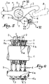
- Fig. 5 is a cross section showing the mounting of an oscillating member between two spacers according to FIG. 4.
- Fig. 6 is a partial section along the plane indicated in VI-VI in FIG. 5.
- FIG. 4 there is shown at 5 a spacer which is pierced with an opening 5 a forming a hub, an annular projection 5 b being advantageously provided on each of the lateral faces of said spacer around the outlet of this opening 5 a .
- the spacer 5 is integral with an extension 6 in the form of an arm which is drilled at 6 a at a diameter much smaller than that of the opening 5 a , this hole 6 a being similarly bordered by two opposite annular projections 6 b .
- bosses 7 are provided which protrude laterally on one and the other of the opposite faces of said part.
- the spacer 5 had four protruding bosses 7 while the arm 6 carried only one.
- Fig. 5 and 6 illustrate the mounting of parts 5-6 and of the oscillating members 2 on the common support axis 1.
- the members 2 are constituted by hooks which under the action of the reading device of the mechanical (action which has been represented in the form of opposite arrows f ), are intended to come to be coupled with fixed hooks 8 corresponding, or to escape these, and this by means of an oscillation of reduced angular amplitude.
- Each oscillating member or hook 2 rubs directly on the support axis 1 provided with a smooth wall.
- the mounting of these hooks and parts 5-6 on this axis 1 presents no difficulty and can be carried out using simple automatic machines, with high efficiency.
- bosses 7, their arrangement and their sectional profile can vary to a very large extent.
Landscapes
- Engineering & Computer Science (AREA)
- Textile Engineering (AREA)
- Looms (AREA)
- Braiding, Manufacturing Of Bobbin-Net Or Lace, And Manufacturing Of Nets By Knotting (AREA)
- Woven Fabrics (AREA)
- Snaps, Bayonet Connections, Set Pins, And Snap Rings (AREA)
Abstract
Description
La présente invention a trait aux mécaniques pour la formation de la foule sur les machines à tisser, le terme "mécaniques" englobant aussi bien les ratières dont le programme d'armure est susceptible d'être aisément modifié, que les mécanismes simplifiés à cames ou similaires, purement répétitifs.The present invention relates to mechanics for forming the crowd on weaving machines, the term "mechanical" including both the dobbies whose armor program is likely to be easily modified, as the simplified mechanisms with cams or similar, purely repetitive.
On sait que pour la manoeuvre individuelle des différents cadres de lisses montés sur le métier, ces mécaniques d'armure comprennent un nombre égal d'ensembles d'actionnement (ensembles généralement désignés sous le nom de "lames") qui sont disposés parallèlement les uns aux autres et dont chacun est formé par une série d'organes oscillants qui coopèrent les uns avec les autres en vue de fournir, au moment opportun qui est fonction de l'armure désirée pour le tissu à réaliser, l'effort nécessaire au déplacement vertical du cadre de lisses correspondant. La nature et la forme de ces organes oscillants varient suivant les différents types de mécaniques, mais on peut retenir qu'il s'agit le plus souvent de leviers, de bielles ou biellettes, de crochets, de porte-galets, etc... animés d'un mouvement angulaire d'une amplitude définie. Bien entendu les organes oscillants identiques des différentes lames sont montés sur un axe-support commun fixé dans le bâti.It is known that for the individual operation of the different heald frames mounted on the loom, these armor mechanics comprise an equal number of actuating assemblies (assemblies generally designated by the name of "blades") which are arranged in parallel to the others and each of which is formed by a series of oscillating members which cooperate with each other in order to provide, at the appropriate time which is a function of the weave desired for the fabric to be produced, the force necessary for the vertical displacement the corresponding heald frame. The nature and shape of these oscillating members vary according to the different types of mechanical, but it can be remembered that they are most often levers, connecting rods or rods, hooks, roller carriers, etc. animated by an angular movement of a defined amplitude. Of course, the identical oscillating members of the different blades are mounted on a common support pin fixed in the frame.
Certains de ces organes oscillants, notamment les crochets de retenue et les leviers de tirage attelés aux cadres de lisses, sont soumis à des efforts élevés, si bien qu'en vue d'éviter tout fléchissement des axes-supports communs, il est nécessaire d'avoir recours à des pièces résistantes de fort diamètre, dont l'encombrement gêne en fait l'implantation dans le bâti, toujours assez exigu, de la mécanique.Some of these oscillating members, in particular the retaining hooks and the pulling levers coupled to the heald frames, are subjected to high forces, so that in order to avoid any deflection of the common support axes, it is necessary to '' have recourse to resistant parts of large diameter, whose bulk hinders in fact the installation in the frame, always quite cramped, of the mechanics.
En pratique, on a proposé différents modes de montage des organes oscillants sur l'axe-support commun, modes dont les trois principaux ont été schématiquement illustrés aux fig. 1 à 3 du dessin annexé aux présentes.In practice, various methods of mounting the oscillating members on the common support axis have been proposed, modes of which the three main ones have been schematically illustrated in FIGS. 1 to 3 of the drawing appended hereto.
Le montage le plus simple est celui suivant fig. 1, dans lequel l'axe fixe 1 supporte directement les organes oscillants 2, disposés côte à côte sans aucune séparation. Dans ces conditions, il est clair que ces organes 2 frottent les uns contre les autres, les frictions ainsi engendrées provoquant des échauffements, une usure sensible et l'apparition de fautes de tissage.The simplest assembly is that according to fig. 1, in which the
Aussi a-t-on proposé le montage individualisé suivant fig. 2, dans lequel les organes 2, toujours directement engagés sur l'axe commun 1, sont séparés les uns des autres par des joncs fendus ou circlips 3, retenus dans des rainures 1a usinées dans la paroi de l'axe. On évite ainsi le frottement mutuel des organes 2, mais la réalisation des rainures 1a et le montage des circlips 3 et des organes 2 eux-mêmes augmentent sensiblement le prix de revient, en même temps que les rainures 1a affaiblissent de manière non négligeable la résistance de l'axe 1 à la flexion.So we proposed the individualized assembly according to fig. 2, in which the
Pour éviter ces inconvénients, on a eu recours à la solution illustrée en fig. 3, dans laquelle l'individualisation des organes oscillants 2 est assurée à l'aide de bagues épaulées 4 interposées entre l'axesupport 1 et le moyeu de chaque organe. Le montage est simplifié et l'axe 1 conserve sa pleine résistance, mais par contre les bagues 4 doivent être réalisées dans des métaux ou alliage spéciaux, donc coûteux, pour résister au frottement. Par ailleurs et surtout, le diamètre de frottement est accru et pour éviter le mauvais rendement ainsi introduit dans la mécanique, il y a lieu de diminuer le diamètre de l'axe 1 en réduisant ainsi sa résistance à la flexion.To avoid these drawbacks, the solution illustrated in FIG. 3, in which the individualization of the oscillating
C'est à ces inconvénients qu'entend remédier la présente invention, et ce à l'aide d'une solution qui permet au moyeu des organes oscillants de frotter directement sur un arbre à paroi lisse, ainsi dépourvu de toute rainure, et qui néanmoins assure l'individualisation desdits organes en vue d'interdire toute friction latérale mutuelle de ceux-ci.It is to these drawbacks that the present invention intends to remedy, and this by means of a solution which allows the hub of the oscillating members to rub directly on a shaft with a smooth wall, thus devoid of any groove, and which nevertheless ensures the individualization of said organs with a view to prohibiting any mutual lateral friction between them.
L'invention a pour objet la mécanique d'armure qui est définie à la revendication 1.The subject of the invention is the armor mechanics which is defined in
En fait l'invention consiste essentiellement à opérer la séparation des organes oscillants contigus à l'aide d'entretoises annulaires qui sont engagées sur l'axe-support entre lesdits organes et qui comportent, sur l'une au moins de leurs faces latérales, des bossages en saillie propres à venir en contact avec l'entretoise adjacente en définissant entre ces deux entretoises un espace libre suffisant pour le montage oscillant d'un organe.In fact, the invention essentially consists in operating the separation of the adjoining oscillating members using annular spacers which are engaged on the support axis between said members and which comprise, on at least one of their lateral faces, projecting bosses capable of coming into contact with the adjacent spacer, defining between these two spacers a sufficient free space for the oscillating mounting of a member.
Le dessin annexé, donné à titre d'exemple, permettra de mieux comprendre l'invention, les caractéristiques qu'elle présente et les avantages qu'elle est susceptible de procurer :The appended drawing, given by way of example, will allow a better understanding of the invention, the characteristics which it presents and the advantages which it is capable of providing:
Comme indiqué plus haut, fig. 1 à 3 sont des coupes schématiques illustrant trois solutions antérieures.As indicated above, fig. 1 to 3 are schematic sections illustrating three previous solutions.
Fig. 4 est une vue en perspective de l'une des entretoises intermédiaires d'individualisation d'une mécanique d'armure établie suivant la présente invention.Fig. 4 is a perspective view of one of the intermediate spacers for individualizing an armor mechanism established according to the present invention.
Fig. 5 est une coupe transversale montrant le montage d'un organe oscillant entre deux entretoises suivant fig. 4.Fig. 5 is a cross section showing the mounting of an oscillating member between two spacers according to FIG. 4.
Fig. 6 est une coupe partielle suivant le plan indiqué en VI-VI en fig. 5.Fig. 6 is a partial section along the plane indicated in VI-VI in FIG. 5.
En fig. 4, on a représenté en 5 une entretoise qui est percée d'une ouverture 5a formant moyeu, une saillie annulaire 5b étant avantageusement prévue sur chacune des faces latérales de ladite entretoise autour du débouché de cette ouverture 5a. L'entretoise 5 est solidaire d'un prolongement 6 en forme de bras qui est percé en 6a à un diamètre nettement inférieur à celui de l'ouverture 5a, ce perçage 6a étant de la même manière bordé par deux saillies annulaires opposées 6b.In fig. 4, there is shown at 5 a spacer which is pierced with an
Sur la pièce 5-6 ainsi profilée, on a prévu une série de bossages 7 qui débordent latéralement sur l'une et l'autre des faces opposées de ladite pièce. Dans l'exemple de réalisation envisagé, on a supposé que l'entretoise 5 présentait quatre bossages débordants 7 tandis que le bras 6 n'en portait qu'un seul.On the part 5-6 thus profiled, a series of
Fig. 5 et 6 illustrent bien le montage des pièces 5-6 et des organes oscillants 2 sur l'axe-support commun 1. Dans le cas envisagé, les organes 2 sont constitués par des crochets qui sous l'action du dispositif de lisage de la mécanique (action qui a été figurée sous la forme de flèches opposées f), sont destinés à venir s'atteler avec des crochets fixes 8 correspondants, ou à échapper à ces derniers, et ce moyennant une oscillation d'amplitude angulaire réduite.Fig. 5 and 6 illustrate the mounting of parts 5-6 and of the oscillating
Entre deux organes ou crochets 2 adjacents est interposée une pièce 5-6 dont le bras 6 est engagé par son perçage 6a sur une tige 9 fixée dans le bâti de la mécanique en étant orientée parallèlement à l'axe 1, la position de cette tige 9 étant telle que l'ensemble des entretoises 5 est retenu angulairement de façon à ce que la partie principale des crochets 2 et leur queue d'actionnement 2a se trouvent disposées entre les bossages 7, en jouissant d'une liberté angulaire suffisante pour leur oscillation. Les bossages 7 de deux pièces 5-6 contiguës peuvent de ce fait venir en butée, en assurant l'espacement correct des crochets 2.Between two adjacent members or
Chaque organe oscillant ou crochet 2 frotte directement sur l'axe-support 1 prévu à paroi lisse. Le montage de ces crochets et des pièces 5-6 sur cet axe 1 ne présente aucune difficulté et peut être effectué à l'aide de machines automatiques simples, à haut rendement.Each oscillating member or hook 2 rubs directly on the
Le nombre des bossages 7, leur disposition et leur profil en section peuvent varier dans une très large mesure.The number of
On conçoit en particulier que compte tenu du gain de place obtenu diamétralement au niveau du moyeu de chaque organe oscillant 2, on peut interposer entre ledit moyeu et l'axe-support 1 un roulement à billes ou à aiguilles, propre à améliorer la rotation. Il va par ailleurs de soi que les bossages 7 de chaque pièce 5-6 sont susceptibles de ne s'étendre que sur une seule face de celle-ci, pour autant qu'il soient prévus suffisament longs pour venir porter contre la face lisse de la pièce adjacente.It is understood in particular that, given the space saving obtained diametrically at the hub of each oscillating
Claims (3)
Applications Claiming Priority (2)
| Application Number | Priority Date | Filing Date | Title |
|---|---|---|---|
| FR9101402A FR2672308B1 (en) | 1991-02-01 | 1991-02-01 | ARMOR MECHANICS FOR CROWD FORMATION ON WEAVING MACHINES. |
| FR9101402 | 1991-02-01 |
Publications (2)
| Publication Number | Publication Date |
|---|---|
| EP0497717A1 true EP0497717A1 (en) | 1992-08-05 |
| EP0497717B1 EP0497717B1 (en) | 1995-03-29 |
Family
ID=9409462
Family Applications (1)
| Application Number | Title | Priority Date | Filing Date |
|---|---|---|---|
| EP92420037A Expired - Lifetime EP0497717B1 (en) | 1991-02-01 | 1992-01-31 | Dobby for forming the shed on weaving looms |
Country Status (7)
| Country | Link |
|---|---|
| US (1) | US5209268A (en) |
| EP (1) | EP0497717B1 (en) |
| JP (1) | JPH07100894B2 (en) |
| KR (1) | KR100225141B1 (en) |
| DE (1) | DE69201807T2 (en) |
| ES (1) | ES2071463T3 (en) |
| FR (1) | FR2672308B1 (en) |
Cited By (2)
| Publication number | Priority date | Publication date | Assignee | Title |
|---|---|---|---|---|
| CN102650085A (en) * | 2011-02-25 | 2012-08-29 | 施托布利法韦日公司 | Spacer and sub-assembly for separating the levers of a shedding machine, machine including such a sub-assembly and installation method |
| CN104213318A (en) * | 2014-08-07 | 2014-12-17 | 扬中市金德纺织机械设备厂 | High speed loom |
Families Citing this family (2)
| Publication number | Priority date | Publication date | Assignee | Title |
|---|---|---|---|---|
| JPH09171765A (en) * | 1995-12-20 | 1997-06-30 | Yazaki Corp | Fuse box |
| FR2884527B1 (en) * | 2005-04-15 | 2007-07-13 | Staubli Faverges Sca | ARMOR CAM MECHANICS, METHOD OF ASSEMBLING SUCH A MECHANICAL AND WEAVING COMPRISING SUCH A MECHANICAL |
Citations (2)
| Publication number | Priority date | Publication date | Assignee | Title |
|---|---|---|---|---|
| FR2425490A1 (en) * | 1978-05-11 | 1979-12-07 | Rueti Ag Maschf | PEDAL FEEDING DEVICE FOR DRIVING THE BLADES OF A Loom |
| FR2599056A1 (en) * | 1986-05-20 | 1987-11-27 | Staubli Sa Ets | Improvements to texture mechanisms for forming shed on weaving machines |
Family Cites Families (6)
| Publication number | Priority date | Publication date | Assignee | Title |
|---|---|---|---|---|
| IT1137825B (en) * | 1981-08-06 | 1986-09-10 | Fimtessile | PERFECTED MEANS OF CONTROL OF THE OSZILLATIONS OF FIXED AND MOVABLE KNIVES AND OF THE MOVEMENTS OF THE HARPES IN A DOBBY FOR WEAVING FRAMES |
| FR2515703B1 (en) * | 1981-11-05 | 1983-12-09 | Staubli Sa Ets | |
| JPS6371053A (en) * | 1986-09-12 | 1988-03-31 | Isamu Miura | Nethod of reversing paper for paper aligning device and mechanism for reversing paper |
| FR2609476B1 (en) * | 1987-01-09 | 1990-12-07 | Staubli Sa Ets | IMPROVEMENTS ON NEGATIVE RATIERS OF THE OSCILLATING BALANCE TYPE |
| IT1229284B (en) * | 1989-04-18 | 1991-08-08 | Nuovo Pignone Spa | MAIN LEVER FOR ROTARY DOBBY WORKING AT HIGH SPEED. |
| DE69029780T2 (en) * | 1989-08-31 | 1997-07-10 | Canon Kk | Suction-regeneration device for an ink jet recording device |
-
1991
- 1991-02-01 FR FR9101402A patent/FR2672308B1/en not_active Expired - Fee Related
-
1992
- 1992-01-31 ES ES92420037T patent/ES2071463T3/en not_active Expired - Lifetime
- 1992-01-31 KR KR1019920001427A patent/KR100225141B1/en not_active IP Right Cessation
- 1992-01-31 JP JP4016703A patent/JPH07100894B2/en not_active Expired - Lifetime
- 1992-01-31 EP EP92420037A patent/EP0497717B1/en not_active Expired - Lifetime
- 1992-01-31 DE DE69201807T patent/DE69201807T2/en not_active Expired - Fee Related
- 1992-02-03 US US07/829,305 patent/US5209268A/en not_active Expired - Lifetime
Patent Citations (2)
| Publication number | Priority date | Publication date | Assignee | Title |
|---|---|---|---|---|
| FR2425490A1 (en) * | 1978-05-11 | 1979-12-07 | Rueti Ag Maschf | PEDAL FEEDING DEVICE FOR DRIVING THE BLADES OF A Loom |
| FR2599056A1 (en) * | 1986-05-20 | 1987-11-27 | Staubli Sa Ets | Improvements to texture mechanisms for forming shed on weaving machines |
Cited By (5)
| Publication number | Priority date | Publication date | Assignee | Title |
|---|---|---|---|---|
| CN102650085A (en) * | 2011-02-25 | 2012-08-29 | 施托布利法韦日公司 | Spacer and sub-assembly for separating the levers of a shedding machine, machine including such a sub-assembly and installation method |
| EP2492381A1 (en) | 2011-02-25 | 2012-08-29 | Staubli Faverges | Spacer and sub-assembly for separating the levers of a shedding machine, machine including such a sub-assembly and installation method |
| FR2972008A1 (en) * | 2011-02-25 | 2012-08-31 | Staubli Sa Ets | SPACER AND LEVER SEPARATION SUB-ASSEMBLY OF A CROW-FORMING MACHINE, MACHINE COMPRISING SUCH A SUBASSEMBLY, AND MOUNTING METHOD |
| CN102650085B (en) * | 2011-02-25 | 2015-08-26 | 施托布利法韦日公司 | For separating of separator and sub-component, the machine comprising described sub-component and the installation method of the bar of tapping machine |
| CN104213318A (en) * | 2014-08-07 | 2014-12-17 | 扬中市金德纺织机械设备厂 | High speed loom |
Also Published As
| Publication number | Publication date |
|---|---|
| EP0497717B1 (en) | 1995-03-29 |
| ES2071463T3 (en) | 1995-06-16 |
| FR2672308A1 (en) | 1992-08-07 |
| FR2672308B1 (en) | 1993-05-07 |
| JPH0617343A (en) | 1994-01-25 |
| DE69201807D1 (en) | 1995-05-04 |
| DE69201807T2 (en) | 1995-11-30 |
| KR920016631A (en) | 1992-09-25 |
| KR100225141B1 (en) | 1999-10-15 |
| JPH07100894B2 (en) | 1995-11-01 |
| US5209268A (en) | 1993-05-11 |
Similar Documents
| Publication | Publication Date | Title |
|---|---|---|
| EP0742298B1 (en) | Rotary dobby for forming the shed on looms | |
| FR2478682A1 (en) | IMPROVEMENTS IN RATIO OF THE ROTARY TYPE FOR WEAVING | |
| EP0497717B1 (en) | Dobby for forming the shed on weaving looms | |
| EP0239514A1 (en) | Rotary dobby for looms | |
| EP0225266B1 (en) | Roll lever for positive heald motion to drive the heald frames of looms | |
| EP0045758B1 (en) | Mechanical control for the shedding of warp ends of a loom and loom comprising such mechanical control | |
| EP3719187B1 (en) | Device for forming a shed and jacquard loom equipped with such a device | |
| EP0488915B1 (en) | Driving system for the knife boxes of a shed-forming mechanism such as a dobby | |
| FR2846343A1 (en) | CROWD FORMATION MECHANISM AND WEAVING MACHINE EQUIPPED WITH SUCH A MECHANISM | |
| EP0325547B1 (en) | Draw system to control the heddle frames of a negative dobby | |
| EP0274455B1 (en) | Negative dobby machines wth oscillating swing levers | |
| BE898160A (en) | Heald control system for a moving loom with moving ripples. | |
| FR2663347A1 (en) | CLOSED CROWD RAIL FOR WEAVING MATERIALS. | |
| EP0131495B1 (en) | Device for making a lenoshed selvedge in looms | |
| EP0457698B1 (en) | Process for mounting the driving elements of rotary dobbies for looms and obtained dobbies | |
| EP0136244B1 (en) | Mechanism for the control of the knife boxes of dobbies | |
| FR2599056A1 (en) | Improvements to texture mechanisms for forming shed on weaving machines | |
| EP0619390A1 (en) | Jacquard mechanism with different lifts | |
| BE1004930A3 (en) | IMPROVED MECHANISM FOR SELECTING THE MOVEMENT OF MOBILE ELEMENTS OF A DEVICE FOR FORMING FOLDED EDGES, PARTICULARLY SUITABLE FOR WEAVING SPONGED TISSUE. | |
| FR2513670A1 (en) | NIPPED OR NEEDLE CHAIN FOR FABRIC TENSION MACHINES | |
| EP1069219B1 (en) | Selvedge shedding device and weaving loom with such a device | |
| FR2849067A1 (en) | Loom heddle has coupling with thrust sections on each end to engage with corresponding surfaces on traction bar attached to frame cross-member | |
| FR2672309A3 (en) | Bobbin for weaving looms | |
| FR2657891A3 (en) | Actuation rod for textile dobbies of the rotary type | |
| BE451185A (en) |
Legal Events
| Date | Code | Title | Description |
|---|---|---|---|
| PUAI | Public reference made under article 153(3) epc to a published international application that has entered the european phase |
Free format text: ORIGINAL CODE: 0009012 |
|
| AK | Designated contracting states |
Kind code of ref document: A1 Designated state(s): BE CH DE ES FR IT LI |
|
| 17P | Request for examination filed |
Effective date: 19921019 |
|
| 17Q | First examination report despatched |
Effective date: 19940905 |
|
| GRAA | (expected) grant |
Free format text: ORIGINAL CODE: 0009210 |
|
| AK | Designated contracting states |
Kind code of ref document: B1 Designated state(s): BE CH DE ES FR IT LI |
|
| REF | Corresponds to: |
Ref document number: 69201807 Country of ref document: DE Date of ref document: 19950504 |
|
| ITF | It: translation for a ep patent filed |
Owner name: MODIANO & ASSOCIATI S.R.L. |
|
| REG | Reference to a national code |
Ref country code: ES Ref legal event code: FG2A Ref document number: 2071463 Country of ref document: ES Kind code of ref document: T3 |
|
| PLBE | No opposition filed within time limit |
Free format text: ORIGINAL CODE: 0009261 |
|
| STAA | Information on the status of an ep patent application or granted ep patent |
Free format text: STATUS: NO OPPOSITION FILED WITHIN TIME LIMIT |
|
| 26N | No opposition filed | ||
| PGFP | Annual fee paid to national office [announced via postgrant information from national office to epo] |
Ref country code: ES Payment date: 20060116 Year of fee payment: 15 |
|
| REG | Reference to a national code |
Ref country code: ES Ref legal event code: FD2A Effective date: 20070201 |
|
| PG25 | Lapsed in a contracting state [announced via postgrant information from national office to epo] |
Ref country code: ES Free format text: LAPSE BECAUSE OF NON-PAYMENT OF DUE FEES Effective date: 20070201 |
|
| PGFP | Annual fee paid to national office [announced via postgrant information from national office to epo] |
Ref country code: CH Payment date: 20081215 Year of fee payment: 18 |
|
| PGFP | Annual fee paid to national office [announced via postgrant information from national office to epo] |
Ref country code: DE Payment date: 20090112 Year of fee payment: 18 |
|
| PGFP | Annual fee paid to national office [announced via postgrant information from national office to epo] |
Ref country code: BE Payment date: 20090205 Year of fee payment: 18 |
|
| PGFP | Annual fee paid to national office [announced via postgrant information from national office to epo] |
Ref country code: IT Payment date: 20090121 Year of fee payment: 18 |
|
| PGFP | Annual fee paid to national office [announced via postgrant information from national office to epo] |
Ref country code: FR Payment date: 20090116 Year of fee payment: 18 |
|
| BERE | Be: lapsed |
Owner name: S.A. DES ETS *STAUBLI (FRANCE) Effective date: 20100131 |
|
| REG | Reference to a national code |
Ref country code: CH Ref legal event code: PL |
|
| REG | Reference to a national code |
Ref country code: FR Ref legal event code: ST Effective date: 20100930 |
|
| PG25 | Lapsed in a contracting state [announced via postgrant information from national office to epo] |
Ref country code: LI Free format text: LAPSE BECAUSE OF NON-PAYMENT OF DUE FEES Effective date: 20100131 Ref country code: FR Free format text: LAPSE BECAUSE OF NON-PAYMENT OF DUE FEES Effective date: 20100201 Ref country code: CH Free format text: LAPSE BECAUSE OF NON-PAYMENT OF DUE FEES Effective date: 20100131 |
|
| PG25 | Lapsed in a contracting state [announced via postgrant information from national office to epo] |
Ref country code: DE Free format text: LAPSE BECAUSE OF NON-PAYMENT OF DUE FEES Effective date: 20100803 |
|
| PG25 | Lapsed in a contracting state [announced via postgrant information from national office to epo] |
Ref country code: BE Free format text: LAPSE BECAUSE OF NON-PAYMENT OF DUE FEES Effective date: 20100131 |
|
| PG25 | Lapsed in a contracting state [announced via postgrant information from national office to epo] |
Ref country code: IT Free format text: LAPSE BECAUSE OF NON-PAYMENT OF DUE FEES Effective date: 20100131 |