EP3718928B1 - Hitzeschildstruktur und hitzeschildtank - Google Patents
Hitzeschildstruktur und hitzeschildtank Download PDFInfo
- Publication number
- EP3718928B1 EP3718928B1 EP18884695.0A EP18884695A EP3718928B1 EP 3718928 B1 EP3718928 B1 EP 3718928B1 EP 18884695 A EP18884695 A EP 18884695A EP 3718928 B1 EP3718928 B1 EP 3718928B1
- Authority
- EP
- European Patent Office
- Prior art keywords
- pad
- heat
- tank
- insulating
- thermal insulation
- Prior art date
- Legal status (The legal status is an assumption and is not a legal conclusion. Google has not performed a legal analysis and makes no representation as to the accuracy of the status listed.)
- Active
Links
- 238000009413 insulation Methods 0.000 claims description 56
- 239000003351 stiffener Substances 0.000 claims description 12
- 238000000926 separation method Methods 0.000 claims description 5
- 238000012986 modification Methods 0.000 description 16
- 230000004048 modification Effects 0.000 description 16
- 239000007789 gas Substances 0.000 description 14
- 239000003949 liquefied natural gas Substances 0.000 description 12
- 238000010586 diagram Methods 0.000 description 6
- 238000003780 insertion Methods 0.000 description 6
- 230000037431 insertion Effects 0.000 description 6
- 239000011810 insulating material Substances 0.000 description 5
- 230000000052 comparative effect Effects 0.000 description 4
- 239000003915 liquefied petroleum gas Substances 0.000 description 4
- 239000007788 liquid Substances 0.000 description 4
- 230000000694 effects Effects 0.000 description 3
- 239000000463 material Substances 0.000 description 3
- 239000000853 adhesive Substances 0.000 description 2
- 230000001070 adhesive effect Effects 0.000 description 2
- 239000012530 fluid Substances 0.000 description 2
- 238000000034 method Methods 0.000 description 2
- XLYOFNOQVPJJNP-UHFFFAOYSA-N water Substances O XLYOFNOQVPJJNP-UHFFFAOYSA-N 0.000 description 2
- 230000009977 dual effect Effects 0.000 description 1
- 238000000605 extraction Methods 0.000 description 1
- 239000011491 glass wool Substances 0.000 description 1
- 238000004904 shortening Methods 0.000 description 1
Images


Classifications
-
- B—PERFORMING OPERATIONS; TRANSPORTING
- B63—SHIPS OR OTHER WATERBORNE VESSELS; RELATED EQUIPMENT
- B63B—SHIPS OR OTHER WATERBORNE VESSELS; EQUIPMENT FOR SHIPPING
- B63B25/00—Load-accommodating arrangements, e.g. stowing, trimming; Vessels characterised thereby
- B63B25/02—Load-accommodating arrangements, e.g. stowing, trimming; Vessels characterised thereby for bulk goods
- B63B25/08—Load-accommodating arrangements, e.g. stowing, trimming; Vessels characterised thereby for bulk goods fluid
- B63B25/12—Load-accommodating arrangements, e.g. stowing, trimming; Vessels characterised thereby for bulk goods fluid closed
- B63B25/16—Load-accommodating arrangements, e.g. stowing, trimming; Vessels characterised thereby for bulk goods fluid closed heat-insulated
-
- F—MECHANICAL ENGINEERING; LIGHTING; HEATING; WEAPONS; BLASTING
- F17—STORING OR DISTRIBUTING GASES OR LIQUIDS
- F17C—VESSELS FOR CONTAINING OR STORING COMPRESSED, LIQUEFIED OR SOLIDIFIED GASES; FIXED-CAPACITY GAS-HOLDERS; FILLING VESSELS WITH, OR DISCHARGING FROM VESSELS, COMPRESSED, LIQUEFIED, OR SOLIDIFIED GASES
- F17C3/00—Vessels not under pressure
- F17C3/02—Vessels not under pressure with provision for thermal insulation
- F17C3/025—Bulk storage in barges or on ships
- F17C3/027—Wallpanels for so-called membrane tanks
-
- F—MECHANICAL ENGINEERING; LIGHTING; HEATING; WEAPONS; BLASTING
- F17—STORING OR DISTRIBUTING GASES OR LIQUIDS
- F17C—VESSELS FOR CONTAINING OR STORING COMPRESSED, LIQUEFIED OR SOLIDIFIED GASES; FIXED-CAPACITY GAS-HOLDERS; FILLING VESSELS WITH, OR DISCHARGING FROM VESSELS, COMPRESSED, LIQUEFIED, OR SOLIDIFIED GASES
- F17C2201/00—Vessel construction, in particular geometry, arrangement or size
- F17C2201/01—Shape
- F17C2201/0147—Shape complex
- F17C2201/0157—Polygonal
-
- F—MECHANICAL ENGINEERING; LIGHTING; HEATING; WEAPONS; BLASTING
- F17—STORING OR DISTRIBUTING GASES OR LIQUIDS
- F17C—VESSELS FOR CONTAINING OR STORING COMPRESSED, LIQUEFIED OR SOLIDIFIED GASES; FIXED-CAPACITY GAS-HOLDERS; FILLING VESSELS WITH, OR DISCHARGING FROM VESSELS, COMPRESSED, LIQUEFIED, OR SOLIDIFIED GASES
- F17C2201/00—Vessel construction, in particular geometry, arrangement or size
- F17C2201/05—Size
- F17C2201/052—Size large (>1000 m3)
-
- F—MECHANICAL ENGINEERING; LIGHTING; HEATING; WEAPONS; BLASTING
- F17—STORING OR DISTRIBUTING GASES OR LIQUIDS
- F17C—VESSELS FOR CONTAINING OR STORING COMPRESSED, LIQUEFIED OR SOLIDIFIED GASES; FIXED-CAPACITY GAS-HOLDERS; FILLING VESSELS WITH, OR DISCHARGING FROM VESSELS, COMPRESSED, LIQUEFIED, OR SOLIDIFIED GASES
- F17C2203/00—Vessel construction, in particular walls or details thereof
- F17C2203/01—Reinforcing or suspension means
- F17C2203/011—Reinforcing means
- F17C2203/012—Reinforcing means on or in the wall, e.g. ribs
-
- F—MECHANICAL ENGINEERING; LIGHTING; HEATING; WEAPONS; BLASTING
- F17—STORING OR DISTRIBUTING GASES OR LIQUIDS
- F17C—VESSELS FOR CONTAINING OR STORING COMPRESSED, LIQUEFIED OR SOLIDIFIED GASES; FIXED-CAPACITY GAS-HOLDERS; FILLING VESSELS WITH, OR DISCHARGING FROM VESSELS, COMPRESSED, LIQUEFIED, OR SOLIDIFIED GASES
- F17C2203/00—Vessel construction, in particular walls or details thereof
- F17C2203/03—Thermal insulations
- F17C2203/0304—Thermal insulations by solid means
- F17C2203/0358—Thermal insulations by solid means in form of panels
-
- F—MECHANICAL ENGINEERING; LIGHTING; HEATING; WEAPONS; BLASTING
- F17—STORING OR DISTRIBUTING GASES OR LIQUIDS
- F17C—VESSELS FOR CONTAINING OR STORING COMPRESSED, LIQUEFIED OR SOLIDIFIED GASES; FIXED-CAPACITY GAS-HOLDERS; FILLING VESSELS WITH, OR DISCHARGING FROM VESSELS, COMPRESSED, LIQUEFIED, OR SOLIDIFIED GASES
- F17C2221/00—Handled fluid, in particular type of fluid
- F17C2221/03—Mixtures
- F17C2221/032—Hydrocarbons
- F17C2221/033—Methane, e.g. natural gas, CNG, LNG, GNL, GNC, PLNG
-
- F—MECHANICAL ENGINEERING; LIGHTING; HEATING; WEAPONS; BLASTING
- F17—STORING OR DISTRIBUTING GASES OR LIQUIDS
- F17C—VESSELS FOR CONTAINING OR STORING COMPRESSED, LIQUEFIED OR SOLIDIFIED GASES; FIXED-CAPACITY GAS-HOLDERS; FILLING VESSELS WITH, OR DISCHARGING FROM VESSELS, COMPRESSED, LIQUEFIED, OR SOLIDIFIED GASES
- F17C2223/00—Handled fluid before transfer, i.e. state of fluid when stored in the vessel or before transfer from the vessel
- F17C2223/01—Handled fluid before transfer, i.e. state of fluid when stored in the vessel or before transfer from the vessel characterised by the phase
- F17C2223/0146—Two-phase
- F17C2223/0153—Liquefied gas, e.g. LPG, GPL
- F17C2223/0161—Liquefied gas, e.g. LPG, GPL cryogenic, e.g. LNG, GNL, PLNG
-
- F—MECHANICAL ENGINEERING; LIGHTING; HEATING; WEAPONS; BLASTING
- F17—STORING OR DISTRIBUTING GASES OR LIQUIDS
- F17C—VESSELS FOR CONTAINING OR STORING COMPRESSED, LIQUEFIED OR SOLIDIFIED GASES; FIXED-CAPACITY GAS-HOLDERS; FILLING VESSELS WITH, OR DISCHARGING FROM VESSELS, COMPRESSED, LIQUEFIED, OR SOLIDIFIED GASES
- F17C2223/00—Handled fluid before transfer, i.e. state of fluid when stored in the vessel or before transfer from the vessel
- F17C2223/03—Handled fluid before transfer, i.e. state of fluid when stored in the vessel or before transfer from the vessel characterised by the pressure level
- F17C2223/033—Small pressure, e.g. for liquefied gas
-
- F—MECHANICAL ENGINEERING; LIGHTING; HEATING; WEAPONS; BLASTING
- F17—STORING OR DISTRIBUTING GASES OR LIQUIDS
- F17C—VESSELS FOR CONTAINING OR STORING COMPRESSED, LIQUEFIED OR SOLIDIFIED GASES; FIXED-CAPACITY GAS-HOLDERS; FILLING VESSELS WITH, OR DISCHARGING FROM VESSELS, COMPRESSED, LIQUEFIED, OR SOLIDIFIED GASES
- F17C2270/00—Applications
- F17C2270/01—Applications for fluid transport or storage
- F17C2270/0102—Applications for fluid transport or storage on or in the water
- F17C2270/0105—Ships
- F17C2270/0107—Wall panels
Definitions
- the present invention relates to a heat-insulating structure and a heat-insulating tank and, more particularly, to a heat-insulating structure suitable for a thermal insulation panel that is disposed on the side surface of a tank and to a heat-insulating tank that includes the heat-insulating structure.
- a liquefied gas tank for storing liquefied gas such as liquefied natural gas (LNG)
- LNG liquefied natural gas
- the liquefied gas stored in the tank easily vaporizes, and hence there is a need to suppress the entry of heat from the tank surface.
- a panel system for installing a plurality of thermal insulation panels configured from a heat-insulating material on the surface of a tank, as disclosed in Patent Literature 1, for example, is already known.
- the heat-insulating structure disclosed in Patent Literature 1 is configured such that a protruding portion is formed in a center section of a thermal insulation block (thermal insulation panel), such that only this protruding portion is brought into contact with the tank surface, and such that the parts of the thermal insulation block other than the protruding portion are formed at a predetermined gap from the tank surface. According to this invention, even when the outer plate of the tank has partially expanded outward, excessive contact between the tank outer plate and the thermal insulation block can be suppressed, and damage to the thermal insulation block and the support members can be suppressed.
- Patent Literature 1 Japanese Utility Model No. 4-40078 .
- the present invention was conceived in view of these problems, and the purpose of the present invention is to provide a heat-insulating structure and a heat-insulating tank that enable support member damage to be suppressed even when a thermal insulation panel is applied to the side surface of the tank.
- a heat-insulating tank having the features of claim 1.
- the thickness Db of the second pad may be configured with a size equal to or less than the thickness Da of the first pad. Furthermore, the thickness Db of the second pad may be configured to vary in size according to the separation thereof from the first pad.
- the second pad may be disposed so as to be in contact with the first pad.
- the thermal insulation panel may have a mark indicating the orientation thereof when same is installed on the side surface of the tank.
- the heat-insulating tank has, on the inside the side surface thereof, a stiffener which is provided so as to extend in a horizontal direction, and the support member is disposed in alignment with the stiffener.
- heat-insulating structure and heat-insulating tank according to the present invention, by installing, in addition to the first pad that supports the thermal insulation panel in a state of being spaced apart from the side surface of the tank, a second pad that is positioned between the thermal insulation panel and the tank and in a position below the first pad, it is possible to draw the lower section of the thermal insulation panel outward using the second pad when the side surface of the tank has expanded outward.
- an external force can be made to act on the lower section of the thermal insulation panel by the second pad, and a drag on the load and the rotational moment that arises in the thermal insulation panel can be formed by this external force, whereby support member damage can be suppressed.
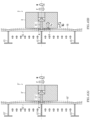
- FIG. 1 is a diagram illustrating a heat-insulating tank according to a first embodiment of the present invention, wherein (A) illustrates a cross-sectional view of a marine vessel in which the heat-insulating tank is installed and (B) illustrates a modification example of the heat-insulating tank.
- Fig. 2 is a side view of the heat-insulating tank in which section A in Fig. 1(A) is enlarged.
- Fig. 1 is a diagram illustrating a heat-insulating tank according to a first embodiment of the present invention, wherein (A) illustrates a cross-sectional view of a marine vessel in which the heat-insulating tank is installed and (B) illustrates a modification example of the heat-insulating tank.
- Fig. 2 is a side view of the heat-insulating tank in which section A in Fig. 1(A) is enlarged.
- FIG. 3 is a diagram illustrating a heat-insulating structure according to the first embodiment of the present invention, where (A) illustrates a plan view, (B) illustrates a cross-sectional view along line B-B in Fig. 3(A), (C) is a first modification example of a second pad, and (D) illustrates a second modification example of the second pad.
- a heat-insulating tank 1 according to the first embodiment of the present invention is a heat-insulating tank over the whole surface of which a heat-insulating structure 2 is formed, the heat-insulating structure 2 being installed on a side surface 1s of the heat-insulating tank 1 on the surface of which a support member 11 is disposed, the heat-insulating tank 1 including: a thermal insulation panel 3 that has, in a center section thereof, a fixed section 31 which is fixed to the support member 11; a first pad 4 that is disposed between the fixed section 31 and the side surface 1s (an outer plate 15) of the heat-insulating tank 1; and a second pad 5 that is disposed in a position below the first pad 4 and between the side surface 1s (the outer plate 15) of the heat-insulating tank 1 and the thermal insulation panel 3.
- the heat-insulating tank 1 illustrated in Fig. 1(A) is a standalone tank-type liquefied gas tank that is mounted in a marine vessel 6 (a liquefied gas carrying vessel) for carrying liquefied gas such as liquefied natural gas (LNG) or liquefied petroleum gas (LPG).
- the marine vessel 6 (liquefied gas carrying vessel) includes a hull 61 disposed on the water and a storage section 62 in which the heat-insulating tank 1 can be mounted, for example.
- the hull 61 has a dual hull structure, for example.
- the storage section 62 is constituted by a space surrounded by the hull 61, and the upper section of the storage section 62 is hermetically covered by a tank cover 63.
- a support member 64 that supports a bottom section 1b of the heat-insulating tank 1 may also be disposed on the bottom section of the storage section 62.
- the heat-insulating tank 1 is not limited to a tank mounted in a liquefied gas carrying vessel and may, for example, be a tank mounted in a floating body storage system that stores liquefied gas such as liquefied natural gas (LNG) or liquefied petroleum gas (LPG) on water, or a liquefied gas tank that is installed above ground.
- LNG liquefied natural gas
- LPG liquefied petroleum gas
- the heat-insulating tank 1 has a substantially rectangular parallelepiped shape configured from the outer plate 15 in which the bottom section 1b, an apex section 1t, and a plurality of side surfaces 1s are formed, and includes a transverse material 12 (large support) disposed on the inside of the outer plate 15; a plurality of stiffeners 13 (small supports) disposed on the inside of the outer plate 15; and a tank dome 14 into which piping or the like for supplying or extracting liquefied gas is inserted.
- the heat-insulating tank 1 is not limited to a rectangular parallelepiped and may have a spherical shape or a cylindrical shape.
- the side surface 1s is also assumed to include an inclined surface which is formed on the bottom section 1b side.
- the heat-insulating tank 1 may also have an inclined surface on the apex section 1t side.
- the side surface 1s is also assumed to include an inclined surface which is formed on the apex section 1t side.
- the side surface 1s signifies not only a vertical surface but also includes a surface which is inclined to the vertical direction.
- the heat-insulating tank 1 illustrated in Fig. 1(B) is illustrated with only its outline showing, and the support members 11, the transverse material 12, the stiffeners 13, and the tank dome 14 are omitted from the illustration.
- the support members 11 whereon the thermal insulation panel 3 is installed are arranged on the surface of the outer plate 15 in correspondence with the positions in which the stiffeners 13 are arranged, for example.
- the support members 11 are configured from a stud bolt 11a which is welded to the surface of the heat-insulating tank 1; a washer 11b which is inserted into the stud bolt 11a; and a nut 11c which is screwed onto the stud bolt 11a.
- the thermal insulation panel 3 is a thermal insulating material that is in a state of being disposed on the outer plate 15 of the side surface 1s of the heat-insulating tank 1 (a usage state) and has a rectangular parallelepiped shape with a vertical height Hp, a horizontal width Wp, and a thickness Dp.
- the vertical height Hp and horizontal width Wp are configured to be substantially the same size but the thermal insulation panel 3 is not limited to such a shape.
- the fixed section 31 of the thermal insulation panel 3 is provided with a long and narrow insertion hole 31a into which the stud bolt 11a can be inserted; an open section 31b that forms a cylindrical-shaped space into which the washer 11b can be inserted; and a lid member 31c that closes the open section 31b.
- the open section 31b has a larger diameter than the insertion hole 31a, and a step section is formed between the insertion hole 31a and the open section 31b.
- the washer 11b is formed with a size enabling contact with the step section.
- the open section 31b has a vertical height Hf and a horizontal width Wf.
- the vertical height Hf and the horizontal width Wf are configured with the same size.
- the first pad 4 is a thermal insulating material and having a long rectangular parallelepiped shape in a horizontal direction in a used state.
- a long and narrow insertion hole 41 into which the stud bolt 11a can be inserted is formed in the center section of the first pad 4.
- the first pad 4 has a vertical height Ha, a horizontal width Wa, and a thickness Da.
- the vertical height Ha is configured to be on the order of 20% of the vertical height Hp of the thermal insulation panel 3 or to be substantially the same size as the vertical height Hf of the open section 31b but is not limited to this number and size.
- the thermal insulation panel 3 When the thermal insulation panel 3 is fixed to the support member 11, first the first pad 4 is threaded onto the stud bolt 11a, and then the thermal insulation panel 3 is threaded onto the stud bolt 11a. Thereafter, the washer 11b is threaded onto the stud bolt 11a from the open section 31b, and the nut 11c is screwed onto the stud bolt 11a. Finally, the open section 31b is sealed by the lid member 31c.
- the method for securing the thermal insulation panel 3 is the same as a conventional fixing method.
- the present embodiment is characterized in that a second pad 5 is installed.
- the second pad 5 is a thermal insulating material and having a long rectangular parallelepiped shape in a horizontal direction in a used state.
- the second pad 5 is disposed so as to be in contact with the lower surface of the first pad 4.
- the second pad 5 is fixed to the thermal insulation panel 3 using adhesive or the like but could also be fixed to the surface of the heat-insulating tank 1.
- the second pad 5 has a vertical height Hb, a horizontal width Wb, and a thickness Db.
- the vertical height Hb is, for example, configured larger than about half the vertical height Ha of the first pad 4 or smaller than about half the horizontal width Wa of the first pad 4.
- the horizontal width Wb is, for example, configured larger than the horizontal width Wf of the open section 31b and smaller than the horizontal width Wa of the first pad 4.
- the thickness Db is configured to be substantially the same size as the thickness Da of the first pad 4, for example.
- the second pad 5 is not limited to the shapes illustrated in Figs. 3(A) and 3(B) .
- a state where the thermal insulation panel 3 is omitted for the sake of expediency is illustrated in Figs. 3(C) and 3(D) .
- the heat-insulating structure 2 is configured from the foregoing thermal insulation panel 3, first pad 4, and second pad 5 and, as illustrated in Fig. 2 , is made to cover the side surfaces 1s of the heat-insulating tank 1 at a predetermined gap therefrom.
- Thermal insulating material having an elastic force such as glass wool is disposed in the gap between the thermal insulation panels 3 (in the sections shaded gray in the drawing).
- the heat-insulating structure 2 eliminates the effect of the self-weight of the thermal insulation panel 3, and therefore the first pad 4 and second pad 5 are preferably used side by side in a vertical direction. Therefore, a conventional heat-insulating structure which does not use the second pad 5 can be used as the heat-insulating structure 2 that is disposed on the bottom section 1b and the apex section 1t of the heat-insulating tank 1.
- the heat-insulating structure 2 according to the present embodiment can be used as long as a state is assumed enabling a gravitational force, however slight, to act on the thermal insulation panel 3, in a direction from the first pad 4 toward the second pad 5.
- the side surface 1s of the heat-insulating tank 1, which uses the heat-insulating structure 2 according to the present embodiment may also include a surface that is inclined relative to the vertical direction illustrated in Figs. 1(A) and 1(B) .
- Fig. 4 is a diagram illustrating the action of the heat-insulating structure illustrated in Figs. 3(A) and 3(B) , where (A) illustrates a comparative view and (B) illustrates the first embodiment.
- the comparative example illustrated in Fig. 4(A) includes a thermal insulation panel 3' and a first pad 4' and illustrates a conventional heat-insulating structure 2' which does not have a second pad.
- only one thermal insulation panel 3, 3' is illustrated for the sake of expediency, other thermal insulation panels being omitted from the illustration.
- the heat-insulating tank 1' of the comparative example has an outer plate 15' that forms a vertical surface, and a plurality of stiffeners 13' are arranged at fixed intervals on the inside of the outer plate 15'. Furthermore, support members 11' are arranged on the surface of the outer plate 15' in positions corresponding to the stiffeners 13'. The first pad 4' and the thermal insulation panel 3' are fixed to the support members 11'.
- LNG liquefied natural gas
- the expansion of the outer plate 15' is absorbed by the gap formed between the thermal insulation panel 3' and the outer plate 15', and hence excessive contact between the outer plate 15' and the thermal insulation panel 3' can be suppressed, and damage to the thermal insulation panel 3' and the support members 11' can be suppressed.
- an external force can be made to act on the lower section of the thermal insulation panel 3 by the second pad 5, drag (a load Fp and a rotational moment Mp) on the self-weight F and rotational moment M which are produced in the thermal insulation panel 3 by the external force can be formed, and damage to the support members 11 can be suppressed.
- the thermal deformation of the heat-insulating tank 1 which accompanies the supplying and extraction of a liquid such as liquefied natural gas (LNG) causes the whole of the outer plate 15 to expand or contract, and hence the effect on the foregoing heat-insulating structure 2 is minimal.
- the heat-insulating structure 2 according to the present embodiment is configured to accommodate the deformation involved in partial expansion of the outer plate 15 when liquid is contained in the heat-insulating tank 1.
- FIG. 5 is a plan view illustrating modification examples of the heat-insulating structure, where (A) illustrates a first modification example and (B) illustrates a second modification example.
- the thermal insulation panel 3 in block form has a shape that is asymmetric in a vertical direction. Hence, there is a risk that the top, bottom, left and right sides of the thermal insulation panel 3 will be positioned erroneously when the heat-insulating structure 2 is implemented.
- a mark 32 indicating the orientation of the thermal insulation panel 3 when same is disposed on the side surface of the heat-insulating tank 1 may be placed on the surface of the thermal insulation panel 3.
- the mark 32 may be provided through printing, stamping, or by attaching a seal.
- downward positioning may be indicated by an arrow as per the first modification example illustrated in Fig. 5(A)
- upward positioning and downward positioning may be indicated by text as per the second modification example illustrated in Fig. 5(B) .
- the mark 32 may be another mark other than an arrow (a circle or the like), may be displayed in English, or may represent all the orientations top, bottom, left, and right.
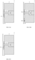
- FIG. 6 is a plan view illustrating heat-insulating structures according to other embodiments of the present invention, where (A) illustrates a second embodiment, (B) illustrates a third embodiment not in the scope of the claims, (C) illustrates a fourth embodiment, and (D) illustrates a fifth embodiment.
- Fig. 7 is a cross-sectional view illustrating heat-insulating structures according to other embodiments of the present invention, where (A) illustrates a sixth embodiment, (B) illustrates a seventh embodiment, and (C) illustrates an eighth embodiment.
- the heat-insulating structure 2 according to the second embodiment illustrated in Fig. 6(A) is configured such that the second pad 5 is disposed in a position spaced apart from the first pad 4.
- the heat-insulating structure 2 according to the third embodiment illustrated in Fig. 6(B) is configured such that the second pad 5 is configured to be integral with the first pad 4.
- the horizontal width of the second pad 5 is configured to be of the same size as the horizontal width of the first pad 4.
- the heat-insulating structure 2 according to the fourth embodiment illustrated in Fig. 6(C) is configured such that the second pad 5 is divided into two and arranged in the respective lower corners of the thermal insulation panel 3.
- the heat-insulating structure 2 according to the fifth embodiment illustrated in Fig. 6(D) is configured by shortening the horizontal width of the first pad 4 illustrated in the fourth embodiment and by forming the vertical surface cross-section of the first pad 4 as a substantially square shape.
- the heat-insulating structure 2 according to the sixth embodiment illustrated in Fig. 7(A) is configured by forming the thickness of the second pad 5 such that same grows thinner as its separation from the first pad 4 increases.
- the second pad 5 has a tapered surface 51, and the tapered surface 51 is disposed so as to not be in contact with the outer plate 15.
- the load Fp and rotational moment Mp which are generated when the outer plate 15 expands, can be optionally adjusted.
- the heat-insulating structure 2 according to the seventh embodiment illustrated in Fig. 7(B) is configured by forming the thickness Db of the second pad 5 to be thinner than the thickness Da of the first pad 4.
- the load Fp and rotational moment Mp, which are generated by the second pad 5 are then also large. Therefore, by adjusting the thickness Db of the second pad 5, the load Fp and rotational moment Mp, which are generated when the outer plate 15 expands, can be optionally adjusted.
- the heat-insulating structure 2 according to the eighth embodiment illustrated in Fig. 7(C) is configured by forming the thickness of the second pad 5 such that same grows thicker as its separation from the first pad 4 increases.
- the thickness of the second pad 5 may be configured to grow thicker as its separation from the first pad 4 increases.
- the second pad 5 has a tapered surface 51 which is in contact with the inclined surface of the outer plate 15.
Claims (6)
- Wärmeisolierender Tank (1), die eine wärmeisolierende Struktur (2) umfasst, die auf einer Seitenfläche (1s) des Tanks (1) angeordnet ist,
wobei eine Versteifung (13) an einer Innenseite der Seitenfläche (1s) des Tanks (1) so vorgesehen ist, dass sie sich in einer horizontalen Richtung erstreckt, und ein Halteelement (11) an der Seitenfläche (1s) des Tanks (1) in Ausrichtung mit der Versteifung (13) installiert ist, wobei die wärmeisolierende Struktur (2) umfasst:eine Wärmedämmplatte (3), die in einem mittleren Abschnitt einen festen Abschnitt (31) aufweist, der an dem Halteelement (11) befestigt ist;eine erste Einlage (4), die zwischen dem festen Abschnitt (31) und der Seitenfläche (1s) des Tanks (1) angeordnet ist; undeine zweite Einlage (5), die in einer Position vertikal unterhalb der ersten Einlage (4) und zwischen der Seitenfläche (1s) des Tanks (1) und der Wärmedämmplatte (3) angeordnet ist, wobei die zweite Einlage (5) in der horizontalen Richtung eine geringere Breite (Wb) als die erste Einlage (4) aufweist. - Wärmeisolierender Tank (1) nach Anspruch 1,
wobei eine Dicke (Db) der zweiten Einlage (5) gleich oder kleiner als eine Dicke (Da) der ersten Einlage (4) ist. - Wärmeisolierender Tank (1) nach Anspruch 2,
wobei die Dicke (Db) der zweiten Einlage (5) in ihrer Größe in Abhängigkeit von ihrem Abstand zu der ersten Einlage (4) variiert. - Wärmeisolierender Tank (1) nach Anspruch 1,
wobei die zweite Einlage (5) so angeordnet ist, dass sie in Kontakt mit der ersten Einlage steht. - Wärmeisolierender Tank (1) nach Anspruch 1,
wobei die zweite Einlage (5) in einer Position angeordnet ist, die von der ersten Einlage (4) beabstandet ist. - Wärmeisolierender Tank (1) nach Anspruch 1, wobei die Wärmedämmplatte (3) eine Markierung (32) aufweist, die ihre Ausrichtung anzeigt, wenn sie auf der Seitenfläche (1s) des Tanks (1) installiert ist.
Applications Claiming Priority (2)
| Application Number | Priority Date | Filing Date | Title |
|---|---|---|---|
| JP2017228407A JP6577006B2 (ja) | 2017-11-28 | 2017-11-28 | 防熱構造及び防熱タンク |
| PCT/JP2018/043102 WO2019107260A1 (ja) | 2017-11-28 | 2018-11-22 | 防熱構造及び防熱タンク |
Publications (3)
| Publication Number | Publication Date |
|---|---|
| EP3718928A1 EP3718928A1 (de) | 2020-10-07 |
| EP3718928A4 EP3718928A4 (de) | 2021-08-11 |
| EP3718928B1 true EP3718928B1 (de) | 2024-02-14 |
Family
ID=66665585
Family Applications (1)
| Application Number | Title | Priority Date | Filing Date |
|---|---|---|---|
| EP18884695.0A Active EP3718928B1 (de) | 2017-11-28 | 2018-11-22 | Hitzeschildstruktur und hitzeschildtank |
Country Status (7)
| Country | Link |
|---|---|
| EP (1) | EP3718928B1 (de) |
| JP (1) | JP6577006B2 (de) |
| KR (1) | KR102357668B1 (de) |
| CN (1) | CN111344234B (de) |
| PH (1) | PH12020550704A1 (de) |
| SG (1) | SG11202004774PA (de) |
| WO (1) | WO2019107260A1 (de) |
Family Cites Families (18)
| Publication number | Priority date | Publication date | Assignee | Title |
|---|---|---|---|---|
| FR2286305A1 (fr) * | 1974-09-27 | 1976-04-23 | Technigaz | Procede de montage d'une structure de paroi composite et structure de paroi composite correspondante |
| US4050609A (en) * | 1976-09-13 | 1977-09-27 | Hitachi Shipbuilding & Engineering Co. | Heat insulating device for low temperature liquified gas storage tanks |
| JPS586114B2 (ja) * | 1980-02-15 | 1983-02-03 | 川崎重工業株式会社 | 低温液化ガス貯蔵タンクのメンブレン基礎 |
| JPH0440078Y2 (de) * | 1985-03-20 | 1992-09-18 | ||
| JPH03131334A (ja) * | 1989-10-17 | 1991-06-04 | Toshiba Corp | 真空容器 |
| JPH0440078U (de) | 1990-08-01 | 1992-04-06 | ||
| JP3511300B2 (ja) * | 1993-05-20 | 2004-03-29 | 株式会社アイ・エイチ・アイ マリンユナイテッド | 液化ガスタンクの保冷パネル高さ調整方法 |
| JP3046239B2 (ja) * | 1996-04-15 | 2000-05-29 | 株式会社森松総合研究所 | タンク用パネル |
| JP3263914B2 (ja) * | 1996-08-15 | 2002-03-11 | 株式会社山武 | 記録計 |
| FR2877639B1 (fr) * | 2004-11-10 | 2006-12-15 | Gaz Transp Et Technigaz Soc Pa | Cuve etanche et thermiquement isolee integree a la stucture porteuse d'un navire |
| FR2877637B1 (fr) * | 2004-11-10 | 2007-01-19 | Gaz Transp Et Technigaz Soc Pa | Cuve etanche et thermiquement isolee a elements calorifuges juxtaposes |
| JP2006077994A (ja) * | 2005-12-02 | 2006-03-23 | Kajima Corp | 防液堤一体型低温タンクの冷熱抵抗緩和材の設置方法および防液堤一体型低温タンク |
| WO2008147003A1 (en) * | 2007-05-29 | 2008-12-04 | Hyundai Heavy Industries Co., Ltd. | Lng storage tank insulation system having welded secondary barrier and construction method thereof |
| DE102007059293B4 (de) * | 2007-12-08 | 2009-09-10 | R & M Ship Tec Gmbh | Auskleidung eines Flüssig-Gas-Behälters mit Mehrschicht-Paneelen und Mehrschicht-Paneel für eine Auskleidung |
| FR2977575B1 (fr) * | 2011-07-06 | 2014-06-27 | Gaztransp Et Technigaz | Coupleur pour maintenir un element par rapport a une structure de retenue |
| KR101625871B1 (ko) * | 2014-07-30 | 2016-06-01 | 삼성중공업 주식회사 | 액화가스 화물창과 그 제조방법 |
| KR20160072291A (ko) * | 2014-12-12 | 2016-06-23 | 삼성중공업 주식회사 | 액화가스 화물창 |
| KR101525476B1 (ko) * | 2014-12-19 | 2015-06-03 | (주)엔아이씨이 | 지지보강재가 구비된 조립식 철제 물탱크 및 그 시공방법 |
-
2017
- 2017-11-28 JP JP2017228407A patent/JP6577006B2/ja active Active
-
2018
- 2018-11-22 CN CN201880073716.0A patent/CN111344234B/zh active Active
- 2018-11-22 WO PCT/JP2018/043102 patent/WO2019107260A1/ja unknown
- 2018-11-22 SG SG11202004774PA patent/SG11202004774PA/en unknown
- 2018-11-22 KR KR1020207013201A patent/KR102357668B1/ko active IP Right Grant
- 2018-11-22 EP EP18884695.0A patent/EP3718928B1/de active Active
-
2020
- 2020-05-26 PH PH12020550704A patent/PH12020550704A1/en unknown
Also Published As
| Publication number | Publication date |
|---|---|
| CN111344234A (zh) | 2020-06-26 |
| WO2019107260A1 (ja) | 2019-06-06 |
| KR102357668B1 (ko) | 2022-02-08 |
| JP6577006B2 (ja) | 2019-09-18 |
| KR20200066685A (ko) | 2020-06-10 |
| SG11202004774PA (en) | 2020-06-29 |
| JP2019099165A (ja) | 2019-06-24 |
| CN111344234B (zh) | 2022-07-12 |
| EP3718928A4 (de) | 2021-08-11 |
| EP3718928A1 (de) | 2020-10-07 |
| PH12020550704A1 (en) | 2021-04-26 |
Similar Documents
| Publication | Publication Date | Title |
|---|---|---|
| CN1786549B (zh) | 液体储罐系统 | |
| EP3165441A1 (de) | Flüssigerdgasspeichertank und isolierwand für den flüssigerdgasspeichertank | |
| KR101616389B1 (ko) | 카고 탱크 구조 및 카고 탱크 구조 설치 방법 | |
| KR101069643B1 (ko) | 액화천연가스 화물창의 보강구조 | |
| KR20170011064A (ko) | 액화천연가스 저장탱크의 고정장치 | |
| KR20150140466A (ko) | 액화가스 화물창 및 이에 사용되는 방벽보강부재 | |
| EP3718928B1 (de) | Hitzeschildstruktur und hitzeschildtank | |
| CN103814249A (zh) | 液化气罐 | |
| EP3165440A1 (de) | Flüssigerdgasspeichertank und isolierwandsicherungsvorrichtung für einen flüssigerdgasspeichertank | |
| JP2022525529A (ja) | 密閉断熱タンク | |
| KR20140004166U (ko) | 독립형 저장탱크의 누출액 수집 장치 | |
| KR20120013220A (ko) | 액화 천연 가스 저장 탱크의 고정 스트립 | |
| JP2015039930A (ja) | 液化ガス運搬船または液化ガス燃料船のタンク支持構造 | |
| KR200441261Y1 (ko) | 인슐레이션 패널의 안전장치 | |
| KR20160004754A (ko) | 액화천연가스 저장탱크 및 액화천연가스 저장 탱크의 단열벽 고정장치 | |
| KR20160004756A (ko) | 액화천연가스 저장탱크 및 액화천연가스 저장 탱크의 단열벽 고정장치 | |
| KR101739463B1 (ko) | 액화천연가스 저장탱크 | |
| KR101985214B1 (ko) | 카고탱크 구조체 및 카고탱크 구조체의 설치방법 | |
| KR20120127244A (ko) | 액화천연가스 저장용기의 구조 | |
| KR101630970B1 (ko) | 저장탱크의 단열재 결합구조 및 시공방법 | |
| KR20190127163A (ko) | 액화가스 저장탱크 및 이를 구비한 해양구조물 | |
| KR20150102233A (ko) | 단열시스템의 체결 구조 및 체결 방법 | |
| KR101422595B1 (ko) | 액화물 저장 탱크의 멤브레인 | |
| KR20190071181A (ko) | 액화가스 화물창의 단열시스템 및 그 단열시스템의 멤브레인 배치구조 | |
| KR20110000877U (ko) | 독립형 저장탱크의 누출액 수집장치 |
Legal Events
| Date | Code | Title | Description |
|---|---|---|---|
| STAA | Information on the status of an ep patent application or granted ep patent |
Free format text: STATUS: THE INTERNATIONAL PUBLICATION HAS BEEN MADE |
|
| PUAI | Public reference made under article 153(3) epc to a published international application that has entered the european phase |
Free format text: ORIGINAL CODE: 0009012 |
|
| STAA | Information on the status of an ep patent application or granted ep patent |
Free format text: STATUS: REQUEST FOR EXAMINATION WAS MADE |
|
| 17P | Request for examination filed |
Effective date: 20200527 |
|
| AK | Designated contracting states |
Kind code of ref document: A1 Designated state(s): AL AT BE BG CH CY CZ DE DK EE ES FI FR GB GR HR HU IE IS IT LI LT LU LV MC MK MT NL NO PL PT RO RS SE SI SK SM TR |
|
| AX | Request for extension of the european patent |
Extension state: BA ME |
|
| DAV | Request for validation of the european patent (deleted) | ||
| DAX | Request for extension of the european patent (deleted) | ||
| A4 | Supplementary search report drawn up and despatched |
Effective date: 20210708 |
|
| RIC1 | Information provided on ipc code assigned before grant |
Ipc: B65D 90/02 20190101AFI20210702BHEP Ipc: B63B 25/16 20060101ALI20210702BHEP Ipc: F17C 3/04 20060101ALI20210702BHEP Ipc: F17C 1/00 20060101ALI20210702BHEP Ipc: F17C 3/02 20060101ALI20210702BHEP |
|
| GRAP | Despatch of communication of intention to grant a patent |
Free format text: ORIGINAL CODE: EPIDOSNIGR1 |
|
| STAA | Information on the status of an ep patent application or granted ep patent |
Free format text: STATUS: GRANT OF PATENT IS INTENDED |
|
| INTG | Intention to grant announced |
Effective date: 20230918 |
|
| GRAS | Grant fee paid |
Free format text: ORIGINAL CODE: EPIDOSNIGR3 |
|
| GRAA | (expected) grant |
Free format text: ORIGINAL CODE: 0009210 |
|
| STAA | Information on the status of an ep patent application or granted ep patent |
Free format text: STATUS: THE PATENT HAS BEEN GRANTED |
|
| AK | Designated contracting states |
Kind code of ref document: B1 Designated state(s): AL AT BE BG CH CY CZ DE DK EE ES FI FR GB GR HR HU IE IS IT LI LT LU LV MC MK MT NL NO PL PT RO RS SE SI SK SM TR |
|
| REG | Reference to a national code |
Ref country code: GB Ref legal event code: FG4D |
|
| REG | Reference to a national code |
Ref country code: CH Ref legal event code: EP |
|
| REG | Reference to a national code |
Ref country code: DE Ref legal event code: R096 Ref document number: 602018065353 Country of ref document: DE |
|
| REG | Reference to a national code |
Ref country code: IE Ref legal event code: FG4D |