EP3718835B1 - Battery swapping platform and battery charging and swapping station having same - Google Patents
Battery swapping platform and battery charging and swapping station having same Download PDFInfo
- Publication number
- EP3718835B1 EP3718835B1 EP18872290.4A EP18872290A EP3718835B1 EP 3718835 B1 EP3718835 B1 EP 3718835B1 EP 18872290 A EP18872290 A EP 18872290A EP 3718835 B1 EP3718835 B1 EP 3718835B1
- Authority
- EP
- European Patent Office
- Prior art keywords
- battery
- transmission member
- battery swap
- swap
- rotating table
- Prior art date
- Legal status (The legal status is an assumption and is not a legal conclusion. Google has not performed a legal analysis and makes no representation as to the accuracy of the status listed.)
- Active
Links
Images



Classifications
-
- B—PERFORMING OPERATIONS; TRANSPORTING
- B60—VEHICLES IN GENERAL
- B60L—PROPULSION OF ELECTRICALLY-PROPELLED VEHICLES; SUPPLYING ELECTRIC POWER FOR AUXILIARY EQUIPMENT OF ELECTRICALLY-PROPELLED VEHICLES; ELECTRODYNAMIC BRAKE SYSTEMS FOR VEHICLES IN GENERAL; MAGNETIC SUSPENSION OR LEVITATION FOR VEHICLES; MONITORING OPERATING VARIABLES OF ELECTRICALLY-PROPELLED VEHICLES; ELECTRIC SAFETY DEVICES FOR ELECTRICALLY-PROPELLED VEHICLES
- B60L53/00—Methods of charging batteries, specially adapted for electric vehicles; Charging stations or on-board charging equipment therefor; Exchange of energy storage elements in electric vehicles
- B60L53/30—Constructional details of charging stations
-
- B—PERFORMING OPERATIONS; TRANSPORTING
- B60—VEHICLES IN GENERAL
- B60L—PROPULSION OF ELECTRICALLY-PROPELLED VEHICLES; SUPPLYING ELECTRIC POWER FOR AUXILIARY EQUIPMENT OF ELECTRICALLY-PROPELLED VEHICLES; ELECTRODYNAMIC BRAKE SYSTEMS FOR VEHICLES IN GENERAL; MAGNETIC SUSPENSION OR LEVITATION FOR VEHICLES; MONITORING OPERATING VARIABLES OF ELECTRICALLY-PROPELLED VEHICLES; ELECTRIC SAFETY DEVICES FOR ELECTRICALLY-PROPELLED VEHICLES
- B60L53/00—Methods of charging batteries, specially adapted for electric vehicles; Charging stations or on-board charging equipment therefor; Exchange of energy storage elements in electric vehicles
- B60L53/80—Exchanging energy storage elements, e.g. removable batteries
-
- Y—GENERAL TAGGING OF NEW TECHNOLOGICAL DEVELOPMENTS; GENERAL TAGGING OF CROSS-SECTIONAL TECHNOLOGIES SPANNING OVER SEVERAL SECTIONS OF THE IPC; TECHNICAL SUBJECTS COVERED BY FORMER USPC CROSS-REFERENCE ART COLLECTIONS [XRACs] AND DIGESTS
- Y02—TECHNOLOGIES OR APPLICATIONS FOR MITIGATION OR ADAPTATION AGAINST CLIMATE CHANGE
- Y02T—CLIMATE CHANGE MITIGATION TECHNOLOGIES RELATED TO TRANSPORTATION
- Y02T10/00—Road transport of goods or passengers
- Y02T10/60—Other road transportation technologies with climate change mitigation effect
- Y02T10/70—Energy storage systems for electromobility, e.g. batteries
-
- Y—GENERAL TAGGING OF NEW TECHNOLOGICAL DEVELOPMENTS; GENERAL TAGGING OF CROSS-SECTIONAL TECHNOLOGIES SPANNING OVER SEVERAL SECTIONS OF THE IPC; TECHNICAL SUBJECTS COVERED BY FORMER USPC CROSS-REFERENCE ART COLLECTIONS [XRACs] AND DIGESTS
- Y02—TECHNOLOGIES OR APPLICATIONS FOR MITIGATION OR ADAPTATION AGAINST CLIMATE CHANGE
- Y02T—CLIMATE CHANGE MITIGATION TECHNOLOGIES RELATED TO TRANSPORTATION
- Y02T10/00—Road transport of goods or passengers
- Y02T10/60—Other road transportation technologies with climate change mitigation effect
- Y02T10/7072—Electromobility specific charging systems or methods for batteries, ultracapacitors, supercapacitors or double-layer capacitors
-
- Y—GENERAL TAGGING OF NEW TECHNOLOGICAL DEVELOPMENTS; GENERAL TAGGING OF CROSS-SECTIONAL TECHNOLOGIES SPANNING OVER SEVERAL SECTIONS OF THE IPC; TECHNICAL SUBJECTS COVERED BY FORMER USPC CROSS-REFERENCE ART COLLECTIONS [XRACs] AND DIGESTS
- Y02—TECHNOLOGIES OR APPLICATIONS FOR MITIGATION OR ADAPTATION AGAINST CLIMATE CHANGE
- Y02T—CLIMATE CHANGE MITIGATION TECHNOLOGIES RELATED TO TRANSPORTATION
- Y02T90/00—Enabling technologies or technologies with a potential or indirect contribution to GHG emissions mitigation
- Y02T90/10—Technologies relating to charging of electric vehicles
- Y02T90/12—Electric charging stations
Definitions
- the invention relates to the field of battery swapping, and in particular to a battery swap platform and a battery charging and swap station comprising the battery swap platform.
- the battery replacement solution is one of the main development directions of power supply because it can replace the traction battery in a very short time and has no obvious influence on the service life of the traction battery.
- battery swap at the bottom of an electric vehicle is a mainstream battery swap method, and this battery swap method is generally completed in a special battery charging and swap station.
- a battery storage for storing batteries, a battery swap platform and a battery swap robot, such as a rail guided vehicle (RGV), for carrying fresh/used traction batteries between the battery storage and the battery swap platform are arranged in the battery charging and swap station.
- the battery swap robot completes the action of replacing the traction battery for the electric vehicle parked on the battery swap platform by reciprocating on track rails laid in advance between the battery storage and the battery swap platform.
- the electric vehicle battery swap platform is generally a direct-entry type platform, that is, after the electric vehicle enters the battery charging and swap station and reaches the battery swap position, the battery swap robot directly enters from between two wheels on one side of the electric vehicle and stops at a projection position of the battery swap position, and then directly detaches a traction battery or directly installs a traction battery for the electric vehicle according to an arrangement direction of the traction battery.
- the disadvantage of this arrangement is that because the projection of the traction battery is generally a rectangle and the direction from the front to the rear of the vehicle is the long side of the rectangle, for battery charging and swap stations with the same battery capacity, the arrangement of the direct-entry type battery swap platform makes the battery storage of the battery charging and swap station need more space to store batteries. That is to say, for battery charging and swap stations with the same capacity, the battery charging and swap station using a direct-entry type battery swap platform has the problem of resource waste caused by a large occupied area.
- CN 206 086 672 U discloses a dolly of plugging into is changed to battery, including elevating system, side telephone-moving structure, running gear and rotary mechanism, elevating system sets up on running gear, the establishment of institution is moved on elevating system to the side, rotary mechanism sets up on the side telephone-moving constructs.
- the holding plate does not provide a rotating table and a guide rail arranged on the rotating table, and thus in case of a battery swap robot to rest thereon, there is no guide rails for the battery swap robot to move along.
- US 2015/151723A1 discloses a battery replacement robot with a mobile storage rack including a mechanical part and an electrical control part.
- the electrical control part controls a battery replacement device to place, in one step, all battery boxes required by one side of an electric bus that needs battery replacement onto a battery box storage rack.
- a battery replacement robot not a battery swap platform for a battery swap robot to rest thereon.
- the invention provides a battery swap platform comprising a fixed structure and a rotating portion, wherein the rotating portion allows a battery swap robot to rest thereon, and the rotating portion is configured to be rotatable by a set angle relative to the fixed structure.
- the rotating portion comprises a rotating table and a guide rail arranged on the rotating table, and the battery swap robot can move along the guide rail.
- the fixed structure comprises a base
- the battery swap platform further comprises a driving portion arranged on the base, and the driving portion can drive the rotating table to rotate.
- the driving portion comprises an electric motor and a first transmission member
- the rotating table is provided with a second transmission member matching the first transmission member
- the electric motor can drive the first transmission member to rotate, thereby driving the second transmission member to rotate.
- a reducer is further arranged between the electric motor and the first transmission member, a third transmission member is arranged on an output shaft of the reducer, and the third transmission member is mated and connected with the first transmission member.
- the first transmission member is a first gear or a linear rack
- the second transmission member is a circumferential rack
- the third transmission member is a second gear
- one of the base and the rotating table is provided with a hole structure
- the other of the base and the rotating table is provided with a shaft structure
- the hole structure and the shaft structure are rotatably connected via a bearing.
- the base is provided with a first positioning hole
- the rotating portion is correspondingly provided with a second positioning hole
- the first positioning hole and the second positioning hole can be connected by a positioning pin inserted therein so as to realize relative fixation of the rotating table and the base.
- the base is fixedly connected to a floor of the battery charging and swap station through bolts, and/or the set angle is 90 degrees.
- the invention also provides a battery charging and swap station, which comprises a battery swap platform, a battery storage and a battery swap robot, wherein the battery swap platform is the battery swap platform in any one of the above technical solutions.
- the battery swap platform comprises a fixed structure, a rotating portion and a driving portion, wherein the driving portion drives the rotating portion to rotate relative to the fixed structure.
- the fixed structure comprises a base.
- the rotating portion comprises a rotating table, a guide rail and a second transmission member.
- the driving portion comprises an electric motor, a reducer, a transmission gear and a first transmission member.
- the first transmission member is a gear or a linear rack
- the second transmission member is a circumferential rack.
- the battery swap platform of the invention can change the orientation of the battery swap robot through the rotation of the rotating table after the battery swap robot reaches the rotating table along the guide rail.
- the battery swap robot can reach the battery swap position more easily from between two wheels on one side of the vehicle, thus reducing the difficulty in design of the battery swap platform; and the traction batteries in the battery storage can also be arranged in a direction perpendicular to the forward direction of the vehicle so as to fully utilize the space of the battery charging and swap station, thereby reducing the occupied area of the battery charging and swap station and saving resources.
- the invention solves the problem of a large occupied area and thus waste of resources of a battery charging and swap station using a direct-entry type battery swap platform.
- the base is further provided with a positioning pin
- the rotating table is correspondingly provided with a positioning hole
- the positioning pin can be fitted with and inserted into the positioning hole after the rotating table rotates by a set angle. It can be seen from this that the positioning pin and the positioning hole enable the rotating table to stop at a set position accurately after rotation, that is, the positioning of the rotating table is more accurate, and the battery swapping stability of the battery swap platform is enhanced.
- first transmission member in the accompanying drawings is described with a cylindrical gear, this arrangement form is not invariable, and those skilled in the art can make adjustments according to needs to adapt to specific applications, for example, the first transmission member can also be a bevel gear or a linear rack, etc.
- the terms “mount”, “engage” and “connect” should be interpreted in a broad sense unless explicitly defined and limited otherwise, which, for example, can mean a fixed connection, a detachable connection or an integral connection; can mean a mechanical connection or an electrical connection; and can mean a direct connection, an indirect connection by means of an intermediary, or internal communication between two elements.
- the specific meaning of the above terms in the invention can be interpreted according to the specific situation.
- Fig. 1 is a schematic layout diagram of a battery charging and swap station in the prior art.
- a battery swap platform is usually arranged in a direct-entry type, wherein a battery swap robot directly enters from between two wheels on one side of an electric vehicle and reaches a projection position of a battery swap position, and then directly detaches a traction battery or directly installs a traction battery for the electric vehicle according to an arrangement direction of the traction battery.
- the battery charging and swap station of the prior art uses the arrangement of a direct-entry type battery swap platform, so that the battery storage of the battery charging and swap station needs more space to store traction batteries. That is to say, for battery charging and swap stations with the same capacity, the battery charging and swap station using a direct-entry type battery swap platform has the problem of resource waste caused by a large occupied area.
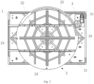
- Fig. 2 is a schematic top view of a battery swap platform (in an initial state) of the invention
- Fig. 3 is a schematic top view of the battery swap platform (in a rotated state) of the invention
- Fig. 4 is a front sectional view of the battery swap platform of the invention.
- the invention provides a battery swap platform, which mainly comprises a fixed structure, a rotating portion 2 and a driving portion 3.
- the fixed structure comprises a base 1, which is fixedly connected to a set position in the charging and changing power station.
- the rotating portion 2 is arranged on the base 1 in a manner that the rotating portion can rotate by a set angle relative to the base 1, for example, after the battery swap robot reaches the rotating portion 2 and stops thereon, the rotating portion 2 rotates by a set angle, while the driving portion 3 can drive the rotating portion 2 to rotate, that is, provide power for the rotation of the rotating portion 2.
- the base 1 is fixedly connected to the floor of the battery charging and swap station by bolts (such as anchor bolts), and the set angle of rotation of the base is 90 degrees.
- the battery swap platform of the invention can change the orientation of the battery swap robot resting thereon, which in turn changes the orientation of the traction battery, thus enabling a rational layout with the space of the battery storage, solving the problem of a large occupied area and thus waste of resources of a battery charging and swap station using a direct-entry type battery swap platform.
- traction batteries since the projection of a traction battery is generally a rectangle, under the condition that the battery swap platform must meet the requirement of the vehicle length, traction batteries must be arranged in the same direction as the installation direction of the traction battery on the electric vehicle (i.e., longitudinal arrangement), and this arrangement tends to cause a waste of space of the battery charging and swap station.
- the arrangement of the traction batteries in the battery storage is more flexible, for example, a direction perpendicular to the installation direction of the traction battery on the electric vehicle (i.e.
- a transverse arrangement can be used, or the combination of the transverse arrangement and the longitudinal arrangement can be used to further enhance the space utilization rate of the battery storage.
- the arrangement of the rotating portion 2 also makes it easier for the battery swap robot to reach the battery swap position from between the two wheels on one side of the vehicle, thus avoiding the phenomenon of battery swap failure caused by motion interference between the battery swap robot and the two wheels on the same side, i.e. reducing the complexity of the battery swap process and the difficulty in the design of the battery swap platform.
- the base 1 can also be fixedly connected through screws or rivets to the floor of the battery charging and swap station or other battery swap storey shelves where the battery swap trolley moves.
- the fixed structure can also be the floor of the battery charging and swap station, and the rotating portion 2 is directly arranged on the floor of the battery charging and swap station in such a way that the rotating portion can rotate by a set angle relative to a bottom surface.
- the set angle may be an angle of any other degrees such as 60 degrees and 75 degrees.
- the rotating portion 2 further comprises a rotating table 21, and a guide rail 22 and a second transmission member 23 which are provided on the rotating table 21, and the rotating table 21 and the base 1 are connected via a bearing 4.
- the driving section 3 further comprises an electric motor 31, a reducer 32 mated and connected with the electric motor 31, a third transmission member 34 provided on an output shaft of the reducer 32, and a first transmission member 33 (see Fig. 5 ) connecting the second transmission member 23 and the third transmission member 34.
- the guide rail 22 on the rotating table 21 can be butted with the guide rail 22 laid in the battery charging and swap station, and the battery swap robot can move to the guide rail 22 on the rotating table 21 along the guide rail 22 laid in the battery charging and swap station and stop at a fixed battery swap position.
- the electric motor 31 can transmit the driving force to the third transmission member 34 through the reducer 32, then the third transmission member 34 drives the first transmission member 33 to move, and then the first transmission member 33 drives the second transmission member 23 to rotate, finally realizing the rotation of the rotating table 21.
- the first transmission member 33 is a first gear, such as a cylindrical or bevel gear
- the second transmission member 23 is a circumferential rack
- the third transmission member 34 is a second gear, such as a cylindrical or bevel gear having specifications different from those of the first gear.
- the base 1 is further provided with a hole structure (not shown), and the rotating table 21 is correspondingly provided with a shaft structure (not shown).
- An outer race of the bearing 4 is closely attached to the hole structure, and an inner race of the bearing 4 is closely attached to the shaft structure.
- the electric motor 31 transmits power to the second gear through the reducer 32 and causes the second gear to rotate.
- the second gear drives the first gear mated therewith to rotate, and then the first gear drives the circumferential rack mated therewith to rotate.
- the rotating table 21 achieves the rotation relative to the base 1 through the bearing 4.
- the rotation of the rotating table 21 can be realized through the combination of standard parts such as the electric motor 31, the reducer 32, the gears and the bearing 4, so that the invention has the advantages of being simple in principle and stable in structure.
- the configuration of the electric motor 31, the reducer 32, and the plurality of gears and racks can also flexibly adjust the specifications, models and combination mode of the above-mentioned equipment or parts based on the actual situation, so as to adjust the rotation speed of the rotating table 21 and make the rotation of the rotating table 21 fast and stable, that is, the battery swap platform of the invention also has the characteristic of high flexibility.
- the arrangement described above of the first transmission member 33, the second transmission member 23 and the third transmission member 34 is not exclusive.
- a transmission with a linear rack and a circumferential rack may be used instead of the current mating of the first gear and the second gear.
- the electric motor 31 drives the linear rack to move linearly in a vertical direction (according to the orientation in Fig. 2 ) through the reducer 32, and the linear rack then drives the circumferential rack to realize the rotational movement of the rotating table 21.
- the base 1 may be further provided with an elongated guide groove in the vertical direction so that the linear rack moves linearly in the vertical direction under the restriction of the guide groove.
- the linear rack and the circumferential rack can move more accurately, which is beneficial to the processing, manufacturing and installation of the driving portion 3, and can also solve the problem that the transmission is influenced by a too large gear clearance caused by inaccurate installation positions of the three gears in the previous preferred solution.
- a first positioning hole (not shown) may also be provided in the base 1.
- the first positioning hole is a kidney-shaped hole.
- At least one second positioning hole 24 is correspondingly provided in the rotating table 21.
- the second positioning holes 24 are two circular holes arranged in a left side and a lower side of the rotating table (according to the orientation in Fig. 2 ).
- the first positioning hole and the second positioning hole 24 can be connected through a positioning pin 5 inserted therein, so as to realize the installation, adjustment and calibration between the rotating table 21 and the base 1, that is, the installation, adjustment and calibration when the battery swap platform is in the initial position and the rotated position, thereby improving the stability and the battery swap success rate of the battery swap platform.
- Fig. 6 is a schematic layout diagram of a battery charging and swap station of the invention.
- the invention also provides a battery charging and swap station, which mainly comprises a battery swap platform, a battery storage and a battery swap robot.
- the battery swap platform is the above-mentioned battery swap platform with the rotating table 21, and the traction batteries in the battery storage are arranged in a direction perpendicular to the forward direction of the electric vehicle (i.e., transversely arranged).
- the traction batteries in the battery storage can be transversely arranged, thus greatly reducing the space of the battery storage, making the arrangement of the equipment in the battery charging and swap station more rational and reducing the occupied area of the battery charging and swap station.
- the battery swap robot detaches the used traction battery ⁇ the rotating table 21 rotates by 90 degrees in a reverse direction and returns to the initial position ⁇ the battery swap robot exits the platform carrying the used traction battery and replaces the used traction battery with a fresh traction battery from the battery storage ⁇ the battery swap robot carries the fresh traction battery to the rotating table 21 ⁇ the rotating table 21 rotates by 90 degrees and reaches the rotated position again ⁇ the battery swap robot installs the fresh traction battery onto the electric vehicle ⁇ the rotating table 21 rotates by 90 degrees in the reverse direction and returns to the initial position ⁇ the battery swap robot exit the rotating table 21 ⁇ the electric vehicle is lowered ⁇ the electric vehicle exits the battery swap platform and the battery swapping is finished.
- the rotating table 21 can rotate by 90 degrees relative to the base 1, and this rotation can change the orientation of the battery swap robot and the traction batteries carried thereon, so that the traction batteries in the battery storage can be placed more flexibly, the space of the platform is fully utilized, dimensions of the space layout of the battery storage are shortened, and thus the occupied area of the whole station is reduced, thereby solving the problems of the large occupied area and waste of resources existing in the battery charging and swap station using the direct-entry type battery swap platform in the prior art, so the invention is suitable for large-scale promotion and application.
Landscapes
- Engineering & Computer Science (AREA)
- Power Engineering (AREA)
- Transportation (AREA)
- Mechanical Engineering (AREA)
- Charge And Discharge Circuits For Batteries Or The Like (AREA)
- Arrangement Or Mounting Of Propulsion Units For Vehicles (AREA)
- Electric Propulsion And Braking For Vehicles (AREA)
- Manipulator (AREA)
Description
- The invention relates to the field of battery swapping, and in particular to a battery swap platform and a battery charging and swap station comprising the battery swap platform.
- With the popularization of new energy vehicles, how to provide fast and effective energy supply for vehicles having insufficient energy has become an issue that concerns car owners and all major manufacturers a lot. Taking electric vehicles as an example, one of the current mainstream power supply solutions is a battery replacement solution. The battery replacement solution is one of the main development directions of power supply because it can replace the traction battery in a very short time and has no obvious influence on the service life of the traction battery. In the battery replacement solution, battery swap at the bottom of an electric vehicle is a mainstream battery swap method, and this battery swap method is generally completed in a special battery charging and swap station. Specifically, a battery storage for storing batteries, a battery swap platform and a battery swap robot, such as a rail guided vehicle (RGV), for carrying fresh/used traction batteries between the battery storage and the battery swap platform are arranged in the battery charging and swap station. The battery swap robot completes the action of replacing the traction battery for the electric vehicle parked on the battery swap platform by reciprocating on track rails laid in advance between the battery storage and the battery swap platform.
- At present, for most battery charging and swap stations, the electric vehicle battery swap platform is generally a direct-entry type platform, that is, after the electric vehicle enters the battery charging and swap station and reaches the battery swap position, the battery swap robot directly enters from between two wheels on one side of the electric vehicle and stops at a projection position of the battery swap position, and then directly detaches a traction battery or directly installs a traction battery for the electric vehicle according to an arrangement direction of the traction battery. However, the disadvantage of this arrangement is that because the projection of the traction battery is generally a rectangle and the direction from the front to the rear of the vehicle is the long side of the rectangle, for battery charging and swap stations with the same battery capacity, the arrangement of the direct-entry type battery swap platform makes the battery storage of the battery charging and swap station need more space to store batteries. That is to say, for battery charging and swap stations with the same capacity, the battery charging and swap station using a direct-entry type battery swap platform has the problem of resource waste caused by a large occupied area.
CN 206 086 672 U discloses a dolly of plugging into is changed to battery, including elevating system, side telephone-moving structure, running gear and rotary mechanism, elevating system sets up on running gear, the establishment of institution is moved on elevating system to the side, rotary mechanism sets up on the side telephone-moving constructs. However, the holding plate does not provide a rotating table and a guide rail arranged on the rotating table, and thus in case of a battery swap robot to rest thereon, there is no guide rails for the battery swap robot to move along.US 2015/151723A1 discloses a battery replacement robot with a mobile storage rack including a mechanical part and an electrical control part. The electrical control part controls a battery replacement device to place, in one step, all battery boxes required by one side of an electric bus that needs battery replacement onto a battery box storage rack. However, it actually provides a structure of a battery replacement robot, not a battery swap platform for a battery swap robot to rest thereon. - Accordingly, there is a need in the art for a novel battery swap platform to solve the above problems.
- In order to solve the above-mentioned problem in the prior art, that is, to solve the problem of waste of resources caused by a large occupied area of a battery charging and swap station using a direct-entry type battery swap platform, the invention provides a battery swap platform comprising a fixed structure and a rotating portion, wherein the rotating portion allows a battery swap robot to rest thereon, and the rotating portion is configured to be rotatable by a set angle relative to the fixed structure.
- The rotating portion comprises a rotating table and a guide rail arranged on the rotating table, and the battery swap robot can move along the guide rail.
- In a preferred technical solution of the battery swap platform described above, the fixed structure comprises a base, the battery swap platform further comprises a driving portion arranged on the base, and the driving portion can drive the rotating table to rotate.
- In a preferred technical solution of the battery swap platform described above, the driving portion comprises an electric motor and a first transmission member, the rotating table is provided with a second transmission member matching the first transmission member, and the electric motor can drive the first transmission member to rotate, thereby driving the second transmission member to rotate.
- In a preferred technical solution of the battery swap platform described above, a reducer is further arranged between the electric motor and the first transmission member, a third transmission member is arranged on an output shaft of the reducer, and the third transmission member is mated and connected with the first transmission member.
- In a preferred technical solution of the battery swap platform described above, the first transmission member is a first gear or a linear rack, and/or the second transmission member is a circumferential rack, and/or the third transmission member is a second gear.
- In a preferred technical solution of the battery swap platform described above, one of the base and the rotating table is provided with a hole structure, the other of the base and the rotating table is provided with a shaft structure, and the hole structure and the shaft structure are rotatably connected via a bearing.
- In a preferred technical solution of the battery swap platform described above, the base is provided with a first positioning hole, the rotating portion is correspondingly provided with a second positioning hole, and the first positioning hole and the second positioning hole can be connected by a positioning pin inserted therein so as to realize relative fixation of the rotating table and the base.
- In a preferred technical solution of the battery swap platform described above, the base is fixedly connected to a floor of the battery charging and swap station through bolts, and/or the set angle is 90 degrees.
- The invention also provides a battery charging and swap station, which comprises a battery swap platform, a battery storage and a battery swap robot, wherein the battery swap platform is the battery swap platform in any one of the above technical solutions.
- Those skilled in the art can understand that in the preferred technical solutions of the invention, the battery swap platform comprises a fixed structure, a rotating portion and a driving portion, wherein the driving portion drives the rotating portion to rotate relative to the fixed structure. The fixed structure comprises a base. The rotating portion comprises a rotating table, a guide rail and a second transmission member. The driving portion comprises an electric motor, a reducer, a transmission gear and a first transmission member. Preferably, the first transmission member is a gear or a linear rack, and the second transmission member is a circumferential rack. With the arrangement in which the driving portion drives the rotating portion to rotate, that is, the electric motor transmits the driving force to the reducer, the reducer drives the transmission gear to rotate, the transmission gear drives the gear or the linear rack to rotate or move linearly, and then the gear or the linear rack drives the circumferential rack arranged on the rotating table to rotate, the battery swap platform of the invention can change the orientation of the battery swap robot through the rotation of the rotating table after the battery swap robot reaches the rotating table along the guide rail. As a result, the battery swap robot can reach the battery swap position more easily from between two wheels on one side of the vehicle, thus reducing the difficulty in design of the battery swap platform; and the traction batteries in the battery storage can also be arranged in a direction perpendicular to the forward direction of the vehicle so as to fully utilize the space of the battery charging and swap station, thereby reducing the occupied area of the battery charging and swap station and saving resources. In other words, the invention solves the problem of a large occupied area and thus waste of resources of a battery charging and swap station using a direct-entry type battery swap platform.
- In addition, the base is further provided with a positioning pin, and the rotating table is correspondingly provided with a positioning hole, and the positioning pin can be fitted with and inserted into the positioning hole after the rotating table rotates by a set angle. It can be seen from this that the positioning pin and the positioning hole enable the rotating table to stop at a set position accurately after rotation, that is, the positioning of the rotating table is more accurate, and the battery swapping stability of the battery swap platform is enhanced.
- Hereinafter, a battery swap platform and a battery charging and swap station comprising the battery swap platform according to the invention will be described with reference to the accompanying drawings. In the accompanying drawings:
-
Fig. 1 is a schematic layout diagram of a battery charging and swap station in the prior art; -
Fig. 2 is a schematic top view of a battery swap platform (in an initial position) of the invention; -
Fig. 3 is a schematic top view of the battery swap platform (in a rotated position) of the invention; -
Fig. 4 is a front sectional view of the battery swap platform of the invention; -
Fig. 5 is a schematic structure diagram of a driving portion of the battery swap platform of the invention; and -
Fig. 6 is a schematic layout diagram of a battery charging and swap station of the invention. - 1. Base; 2. Rotating portion; 21. Rotating table; 22. Guide rail; 23. Second transmission member; 24. Second positioning hole; 3. Driving portion; 31. Electric motor; 32. Reducer; 33. First transmission member; 34. Third transmission member; 4. Bearing; 5. Positioning pin.
- Preferred embodiments of the invention are described below with reference to the accompanying drawings. It should be understood by those skilled in the art that these embodiments are only for explaining the technical principles of the invention and are not intended to limit the scope of protection of the invention. For example, although the first transmission member in the accompanying drawings is described with a cylindrical gear, this arrangement form is not invariable, and those skilled in the art can make adjustments according to needs to adapt to specific applications, for example, the first transmission member can also be a bevel gear or a linear rack, etc.
- It should be noted that in the description of the invention, the terms, such as "center", "upper", "lower", "left", "right", "vertical", "horizontal", "inner" and "outer", that indicate directions or positional relationships are based on the directions or positional relationships shown in the drawings only for convenience of description, and do not indicate or imply that the device or element must have a specific orientation, be constructed and operated in a specific orientation, and therefore cannot be understood as limitation to the invention. In addition, the terms "first", "second" and "third" are for descriptive purposes only and should not be construed as indicating or implying relative importance.
- In addition, it should also be noted that, in the description of the invention, the terms "mount", "engage" and "connect" should be interpreted in a broad sense unless explicitly defined and limited otherwise, which, for example, can mean a fixed connection, a detachable connection or an integral connection; can mean a mechanical connection or an electrical connection; and can mean a direct connection, an indirect connection by means of an intermediary, or internal communication between two elements. For those skilled in the art, the specific meaning of the above terms in the invention can be interpreted according to the specific situation.
- First of all, referring to
Fig. 1, Fig. 1 is a schematic layout diagram of a battery charging and swap station in the prior art. As shown inFig. 1 , in the battery charging and swap station in the prior art, a battery swap platform is usually arranged in a direct-entry type, wherein a battery swap robot directly enters from between two wheels on one side of an electric vehicle and reaches a projection position of a battery swap position, and then directly detaches a traction battery or directly installs a traction battery for the electric vehicle according to an arrangement direction of the traction battery. As mentioned in the background art, the battery charging and swap station of the prior art uses the arrangement of a direct-entry type battery swap platform, so that the battery storage of the battery charging and swap station needs more space to store traction batteries. That is to say, for battery charging and swap stations with the same capacity, the battery charging and swap station using a direct-entry type battery swap platform has the problem of resource waste caused by a large occupied area. - Next, the principle of the invention will be explained with reference to
Figs. 2 to 4 .Fig. 2 is a schematic top view of a battery swap platform (in an initial state) of the invention,Fig. 3 is a schematic top view of the battery swap platform (in a rotated state) of the invention, andFig. 4 is a front sectional view of the battery swap platform of the invention. - As shown in
Fig. 2 , in order to solve the above problem, the invention provides a battery swap platform, which mainly comprises a fixed structure, a rotatingportion 2 and a driving portion 3. The fixed structure comprises abase 1, which is fixedly connected to a set position in the charging and changing power station. The rotatingportion 2 is arranged on thebase 1 in a manner that the rotating portion can rotate by a set angle relative to thebase 1, for example, after the battery swap robot reaches therotating portion 2 and stops thereon, the rotatingportion 2 rotates by a set angle, while the driving portion 3 can drive the rotatingportion 2 to rotate, that is, provide power for the rotation of therotating portion 2. Preferably, thebase 1 is fixedly connected to the floor of the battery charging and swap station by bolts (such as anchor bolts), and the set angle of rotation of the base is 90 degrees. - It can be seen that through the arrangement of the
rotating portion 2 described above, the battery swap platform of the invention can change the orientation of the battery swap robot resting thereon, which in turn changes the orientation of the traction battery, thus enabling a rational layout with the space of the battery storage, solving the problem of a large occupied area and thus waste of resources of a battery charging and swap station using a direct-entry type battery swap platform. Specifically, referring to the prior art inFig. 1 , it can be seen that since the projection of a traction battery is generally a rectangle, under the condition that the battery swap platform must meet the requirement of the vehicle length, traction batteries must be arranged in the same direction as the installation direction of the traction battery on the electric vehicle (i.e., longitudinal arrangement), and this arrangement tends to cause a waste of space of the battery charging and swap station. However, due to the fact that the orientation of the battery swap robot/traction battery can be changed according to the invention, the arrangement of the traction batteries in the battery storage is more flexible, for example, a direction perpendicular to the installation direction of the traction battery on the electric vehicle (i.e. a transverse arrangement) can be used, or the combination of the transverse arrangement and the longitudinal arrangement can be used to further enhance the space utilization rate of the battery storage. Further, The arrangement of therotating portion 2 also makes it easier for the battery swap robot to reach the battery swap position from between the two wheels on one side of the vehicle, thus avoiding the phenomenon of battery swap failure caused by motion interference between the battery swap robot and the two wheels on the same side, i.e. reducing the complexity of the battery swap process and the difficulty in the design of the battery swap platform. - Certainly, the preferred arrangement above is only used to illustrate the principle of the invention, and is not used to limit the scope of protection of the invention. Without departing from the principle of the invention, those skilled in the art can make any form of adjustment. For example, the
base 1 can also be fixedly connected through screws or rivets to the floor of the battery charging and swap station or other battery swap storey shelves where the battery swap trolley moves. The fixed structure can also be the floor of the battery charging and swap station, and therotating portion 2 is directly arranged on the floor of the battery charging and swap station in such a way that the rotating portion can rotate by a set angle relative to a bottom surface. In addition, the set angle may be an angle of any other degrees such as 60 degrees and 75 degrees. - Referring further to
Figs. 2 to 5 , in a preferred embodiment, the rotatingportion 2 further comprises a rotating table 21, and aguide rail 22 and asecond transmission member 23 which are provided on the rotating table 21, and the rotating table 21 and thebase 1 are connected via abearing 4. The driving section 3 further comprises anelectric motor 31, areducer 32 mated and connected with theelectric motor 31, athird transmission member 34 provided on an output shaft of thereducer 32, and a first transmission member 33 (seeFig. 5 ) connecting thesecond transmission member 23 and thethird transmission member 34. When installed, theguide rail 22 on the rotating table 21 can be butted with theguide rail 22 laid in the battery charging and swap station, and the battery swap robot can move to theguide rail 22 on the rotating table 21 along theguide rail 22 laid in the battery charging and swap station and stop at a fixed battery swap position. Theelectric motor 31 can transmit the driving force to thethird transmission member 34 through thereducer 32, then thethird transmission member 34 drives thefirst transmission member 33 to move, and then thefirst transmission member 33 drives thesecond transmission member 23 to rotate, finally realizing the rotation of the rotating table 21. - Preferably, the
first transmission member 33 is a first gear, such as a cylindrical or bevel gear, thesecond transmission member 23 is a circumferential rack, and thethird transmission member 34 is a second gear, such as a cylindrical or bevel gear having specifications different from those of the first gear. Preferably, thebase 1 is further provided with a hole structure (not shown), and the rotating table 21 is correspondingly provided with a shaft structure (not shown). An outer race of thebearing 4 is closely attached to the hole structure, and an inner race of thebearing 4 is closely attached to the shaft structure. Certainly, the positions where the shaft structure and the hole structure are provided can be interchanged. - Referring to
Figs. 2 and3 , that is to say, theelectric motor 31 transmits power to the second gear through thereducer 32 and causes the second gear to rotate. The second gear drives the first gear mated therewith to rotate, and then the first gear drives the circumferential rack mated therewith to rotate. Finally, the rotating table 21 achieves the rotation relative to thebase 1 through thebearing 4. - The above arrangement has the following advantages. First of all, the rotation of the rotating table 21 can be realized through the combination of standard parts such as the
electric motor 31, thereducer 32, the gears and thebearing 4, so that the invention has the advantages of being simple in principle and stable in structure. Secondly, the configuration of theelectric motor 31, thereducer 32, and the plurality of gears and racks can also flexibly adjust the specifications, models and combination mode of the above-mentioned equipment or parts based on the actual situation, so as to adjust the rotation speed of the rotating table 21 and make the rotation of the rotating table 21 fast and stable, that is, the battery swap platform of the invention also has the characteristic of high flexibility. - For this reason, the arrangement described above of the
first transmission member 33, thesecond transmission member 23 and thethird transmission member 34 is not exclusive. In another preferred embodiment, a transmission with a linear rack and a circumferential rack may be used instead of the current mating of the first gear and the second gear. In the preferred solution, theelectric motor 31 drives the linear rack to move linearly in a vertical direction (according to the orientation inFig. 2 ) through thereducer 32, and the linear rack then drives the circumferential rack to realize the rotational movement of the rotating table 21. It is further preferable that thebase 1 may be further provided with an elongated guide groove in the vertical direction so that the linear rack moves linearly in the vertical direction under the restriction of the guide groove. In this way, the linear rack and the circumferential rack can move more accurately, which is beneficial to the processing, manufacturing and installation of the driving portion 3, and can also solve the problem that the transmission is influenced by a too large gear clearance caused by inaccurate installation positions of the three gears in the previous preferred solution. - Referring to
Figs. 2 and4 , in a more preferred embodiment, in order to further enhance the rotation accuracy and stability of the rotating table 21 and facilitate the installation, adjustment and calibration between the rotating table 21 and thebase 1, a first positioning hole (not shown) may also be provided in thebase 1. Preferably, the first positioning hole is a kidney-shaped hole. At least onesecond positioning hole 24 is correspondingly provided in the rotating table 21. Preferably, the second positioning holes 24 are two circular holes arranged in a left side and a lower side of the rotating table (according to the orientation inFig. 2 ). The first positioning hole and thesecond positioning hole 24 can be connected through apositioning pin 5 inserted therein, so as to realize the installation, adjustment and calibration between the rotating table 21 and thebase 1, that is, the installation, adjustment and calibration when the battery swap platform is in the initial position and the rotated position, thereby improving the stability and the battery swap success rate of the battery swap platform. - Now referring to
Fig. 6, Fig. 6 is a schematic layout diagram of a battery charging and swap station of the invention. - As shown in
Fig. 6 , the invention also provides a battery charging and swap station, which mainly comprises a battery swap platform, a battery storage and a battery swap robot. Preferably, the battery swap platform is the above-mentioned battery swap platform with the rotating table 21, and the traction batteries in the battery storage are arranged in a direction perpendicular to the forward direction of the electric vehicle (i.e., transversely arranged). As can be clearly seen fromFig. 6 , due to the battery swap platform with the rotating table 21 used in the battery charging and swap station of the invention, the traction batteries in the battery storage can be transversely arranged, thus greatly reducing the space of the battery storage, making the arrangement of the equipment in the battery charging and swap station more rational and reducing the occupied area of the battery charging and swap station. - Finally, referring to
Figs. 2 ,3 and6 , the working principle of the battery swap platform of the invention will be described with a complete battery swap process as an example. - An electric vehicle is parked at the battery swap position, at which time the rotating table 21 is in the initial position (i.e. the position shown in
Fig. 2 ) → the electric vehicle is positioned and lifted → the battery swap robot moves to the rotating table 21 below the electric vehicle → the rotating table 21 rotates by 90 degrees and reaches the rotated position (i.e. the position shown inFig. 3 ) → the battery swap robot detaches the used traction battery → the rotating table 21 rotates by 90 degrees in a reverse direction and returns to the initial position → the battery swap robot exits the platform carrying the used traction battery and replaces the used traction battery with a fresh traction battery from the battery storage → the battery swap robot carries the fresh traction battery to the rotating table 21 → the rotating table 21 rotates by 90 degrees and reaches the rotated position again → the battery swap robot installs the fresh traction battery onto the electric vehicle → the rotating table 21 rotates by 90 degrees in the reverse direction and returns to the initial position → the battery swap robot exit the rotating table 21 → the electric vehicle is lowered → the electric vehicle exits the battery swap platform and the battery swapping is finished. - To sum up, according to the invention, by providing the battery swap platform with the rotating table 21 rotatable by a set angle and the driving portion 3 supplying power for the rotating table 21, the rotating table 21 can rotate by 90 degrees relative to the
base 1, and this rotation can change the orientation of the battery swap robot and the traction batteries carried thereon, so that the traction batteries in the battery storage can be placed more flexibly, the space of the platform is fully utilized, dimensions of the space layout of the battery storage are shortened, and thus the occupied area of the whole station is reduced, thereby solving the problems of the large occupied area and waste of resources existing in the battery charging and swap station using the direct-entry type battery swap platform in the prior art, so the invention is suitable for large-scale promotion and application.
Claims (9)
- A battery swap platform comprising a fixed structure and a rotating portion (2),
characterized in thatthe rotating portion (2) is configured to allow a battery swap robot to rest thereon, and the rotating portion (2) is configured to be rotatable by a set angle relative to the fixed structure; andwherein the rotating portion (2) comprises a rotating table (21) and a guide rail (22) arranged on the rotating table (21), the guide rail (22) being configured to allow the battery swap robot to move along it. - The battery swap platform according to claim 1, characterized in that the fixed structure comprises a base (1), the battery swap platform further comprises a driving portion (3) arranged on the base (1), and the driving portion (3) can drive the rotating table(21) to rotate.
- The battery swap platform according to claim 2, characterized in that the driving portion (3) comprises an electric motor (31) and a first transmission member (33), the rotating table (21) is provided with a second transmission member (23) matching the first transmission member (33), and the electric motor (31) can drive the first transmission member (33) to rotate, thereby driving the second transmission member (23) to rotate.
- The battery swap platform according to claim 3, characterized in that a reducer (32) is further arranged between the electric motor (31) and the first transmission member (33), a third transmission member (34) is arranged on an output shaft of the reducer (32), and the third transmission member (34) is mated and connected with the first transmission member (33).
- The battery swap platform according to claim 4, characterized in that the first transmission member (33) is a first gear or a linear rack, and/or the second transmission member (23) is a circumferential rack, and/or the third transmission member (34) is a second gear.
- The battery swap platform according to any one of claims 2 to 5, characterized in that one of the base (1) and the rotating table (21) is provided with a hole structure, the other of the base (1) and the rotating table (21) is provided with a shaft structure, and the hole structure and the shaft structure are rotatably connected via a bearing.
- The battery swap platform according to claim 6, characterized in that the base (1) is provided with a first positioning hole, the rotating portion (2) is correspondingly provided with a second positioning hole (24), and the first positioning hole and the second positioning hole (24) can be connected by a positioning pin (5) inserted therein so as to realize relative fixation of the rotating table (21) and the base (1).
- The battery swap platform according to claim 2, characterized in that the base (1) is configured to be fixedly connected to a floor of the battery charging and swap station through bolts, and/or the set angle is 90 degrees.
- A battery charging and swapping station, which comprises a battery swap platform, a battery storage and a battery swap robot, characterized in that the battery swap platform is the battery swap platform according to any of claims 1 to 8.
Applications Claiming Priority (2)
| Application Number | Priority Date | Filing Date | Title |
|---|---|---|---|
| CN201721424676.9U CN207481873U (en) | 2017-10-31 | 2017-10-31 | Trade electric platform and including this trade electric platform fill and trade power station |
| PCT/CN2018/074819 WO2019085305A1 (en) | 2017-10-31 | 2018-01-31 | Battery swapping platform and battery charging and swapping station having same |
Publications (3)
| Publication Number | Publication Date |
|---|---|
| EP3718835A1 EP3718835A1 (en) | 2020-10-07 |
| EP3718835A4 EP3718835A4 (en) | 2021-08-04 |
| EP3718835B1 true EP3718835B1 (en) | 2024-12-04 |
Family
ID=62478441
Family Applications (1)
| Application Number | Title | Priority Date | Filing Date |
|---|---|---|---|
| EP18872290.4A Active EP3718835B1 (en) | 2017-10-31 | 2018-01-31 | Battery swapping platform and battery charging and swapping station having same |
Country Status (5)
| Country | Link |
|---|---|
| EP (1) | EP3718835B1 (en) |
| CN (1) | CN207481873U (en) |
| HK (1) | HK1252188A2 (en) |
| TW (1) | TWM582007U (en) |
| WO (1) | WO2019085305A1 (en) |
Families Citing this family (23)
| Publication number | Priority date | Publication date | Assignee | Title |
|---|---|---|---|---|
| CN208855603U (en) * | 2018-08-13 | 2019-05-14 | 蔚来汽车有限公司 | Rotating mechanism and battery replacing rotating platform |
| CN109515401B (en) * | 2018-10-25 | 2024-05-17 | 蔚来(安徽)控股有限公司 | Vehicle battery replacement platform and vehicle battery replacement system |
| CN110077368A (en) * | 2019-05-23 | 2019-08-02 | 上海蔚来汽车有限公司 | Modular electrical changing station |
| CN110696894A (en) * | 2019-08-14 | 2020-01-17 | 高学才 | Transfer box transfer trolley for power change station |
| CN113054693B (en) * | 2019-12-27 | 2023-11-17 | 沈阳新松机器人自动化股份有限公司 | A charging station electrode adjustment mechanism |
| CN113147492B (en) * | 2020-01-23 | 2024-12-06 | 奥动新能源汽车科技有限公司 | Passage door limit device and battery swap station |
| CN112320684B (en) * | 2020-11-17 | 2022-05-06 | 重庆峘能电动车科技有限公司 | Battery taking and placing device and battery replacing station |
| CN112721722A (en) * | 2021-02-03 | 2021-04-30 | 上海弗则新能源科技有限公司 | Rotation type battery replacement station and battery replacement method in rotation |
| CN113428036B (en) * | 2021-07-19 | 2023-03-14 | 中国煤炭科工集团太原研究院有限公司 | Automatic charging platform of high-capacity power supply device for underground coal mine |
| EP4212382B1 (en) * | 2021-08-27 | 2025-08-06 | Contemporary Amperex Technology (Hong Kong) Limited | Battery swapping platform and a battery swapping station |
| CN217320103U (en) * | 2022-01-29 | 2022-08-30 | 时代电服科技有限公司 | Battery replacing equipment and battery replacing station |
| CN217347551U (en) * | 2022-03-01 | 2022-09-02 | 时代电服科技有限公司 | Battery changing platform and battery changing system |
| CN217515003U (en) * | 2022-03-31 | 2022-09-30 | 时代电服科技有限公司 | Battery replacing system and battery replacing platform thereof |
| CN115817260A (en) * | 2022-03-31 | 2023-03-21 | 时代电服科技有限公司 | Battery replacement method, device, controller and replacement station |
| CN116945957A (en) * | 2022-04-14 | 2023-10-27 | 时代电服科技有限公司 | Battery replacement method and battery replacement station for electric device |
| CN114670700B (en) * | 2022-04-25 | 2025-11-04 | 安徽巨一科技股份有限公司 | A battery swapping trolley for a battery swapping station |
| CN116533942A (en) * | 2022-12-01 | 2023-08-04 | 奥动新能源汽车科技有限公司 | Quick-change equipment with rotation adjustment angle and battery changing trolley |
| JP7826920B2 (en) * | 2022-12-05 | 2026-03-10 | トヨタ自動車株式会社 | Battery replacement device and battery replacement method |
| CN115817419A (en) * | 2023-02-14 | 2023-03-21 | 宁波格劳博智能工业有限公司 | Battery replacing equipment, battery replacing station and battery replacing method |
| CN116317838B (en) * | 2023-05-24 | 2023-08-25 | 安徽元横能源科技有限公司 | Intelligent photovoltaic electric energy storage system |
| CN116331057B (en) * | 2023-05-30 | 2023-10-27 | 宁德时代新能源科技股份有限公司 | Battery replacing device, battery replacing device self-maintenance method, electronic equipment and battery replacing station |
| CN116653876B (en) * | 2023-07-21 | 2023-11-14 | 北京榆构有限公司 | Assembled power exchange station |
| CN118977682A (en) * | 2023-12-29 | 2024-11-19 | 奥动新能源汽车科技有限公司 | Battery swapping equipment and battery swapping station including the same |
Citations (1)
| Publication number | Priority date | Publication date | Assignee | Title |
|---|---|---|---|---|
| CN106891865A (en) * | 2016-10-12 | 2017-06-27 | 蔚来汽车有限公司 | Chassis type battery replacement station for electric automobile and battery replacement method thereof |
Family Cites Families (5)
| Publication number | Priority date | Publication date | Assignee | Title |
|---|---|---|---|---|
| CN102328636B (en) * | 2011-07-13 | 2013-03-20 | 山东电力研究院 | Passenger vehicle electricity-changing platform system capable of realizing automatic attitude adjustment and vehicle positioning |
| CN102407832A (en) * | 2011-09-28 | 2012-04-11 | 山东电力集团公司临沂供电公司 | Battery replacing platform system for positioning electric passenger vehicle |
| CN102700513B (en) * | 2012-06-29 | 2015-02-04 | 山东鲁能智能技术有限公司 | Battery replacement robot with mobile temporary storage frame and battery replacement method |
| CN206086672U (en) * | 2016-10-15 | 2017-04-12 | 南通中远重工有限公司 | Dolly of plugging into is changed to battery |
| CN106740726A (en) * | 2016-12-30 | 2017-05-31 | 天津市津电能源科技发展有限公司 | A kind of robot of dismounting cell |
-
2017
- 2017-10-31 CN CN201721424676.9U patent/CN207481873U/en active Active
-
2018
- 2018-01-31 WO PCT/CN2018/074819 patent/WO2019085305A1/en not_active Ceased
- 2018-01-31 EP EP18872290.4A patent/EP3718835B1/en active Active
- 2018-10-16 HK HK18113276.8A patent/HK1252188A2/en unknown
- 2018-10-16 TW TW107213990U patent/TWM582007U/en not_active IP Right Cessation
Patent Citations (1)
| Publication number | Priority date | Publication date | Assignee | Title |
|---|---|---|---|---|
| CN106891865A (en) * | 2016-10-12 | 2017-06-27 | 蔚来汽车有限公司 | Chassis type battery replacement station for electric automobile and battery replacement method thereof |
Also Published As
| Publication number | Publication date |
|---|---|
| TWM582007U (en) | 2019-08-11 |
| HK1252188A2 (en) | 2019-05-17 |
| CN207481873U (en) | 2018-06-12 |
| EP3718835A4 (en) | 2021-08-04 |
| WO2019085305A1 (en) | 2019-05-09 |
| EP3718835A1 (en) | 2020-10-07 |
Similar Documents
| Publication | Publication Date | Title |
|---|---|---|
| EP3718835B1 (en) | Battery swapping platform and battery charging and swapping station having same | |
| EP3725606A1 (en) | Battery charging and swapping station | |
| US12325386B2 (en) | Battery swapping platform and battery swapping station | |
| CN105946548B (en) | Homing guidance formula handling device | |
| CN110077365B (en) | Quick power change system and quick power change method | |
| CN115285078B (en) | A battery swap station | |
| CN212667169U (en) | Battery replacement system | |
| CN209581427U (en) | Quick battery swap system | |
| CN111823931A (en) | An intelligent power exchange control method for electric passenger cars of different models | |
| CN206719180U (en) | A jacking system used to eliminate the suspension effect of the vehicle when changing the battery of the vehicle chassis | |
| CN210174831U (en) | Battery swapping equipment | |
| CN120863944A (en) | Unmanned aerial vehicle nest automatic take-off and landing buffering, charging and load changing linkage device | |
| CN209617113U (en) | Battery quick swapping and transmission system, battery swapping platform and charging and swapping station | |
| WO2020082841A1 (en) | Electric car battery sharing system and battery swapping method | |
| CN105059267A (en) | A control method for power battery shelves based on mobile power battery replacement | |
| CN207809354U (en) | Charging and swapping station | |
| CN209553159U (en) | Positioning and lifting system for power swapping platform, power swapping platform and charging and swapping station | |
| CN210029865U (en) | Lifting device and charging and replacing station comprising same | |
| CN105015508A (en) | Energy supplementing method and mechanism design for battery powered platform | |
| US11865909B2 (en) | Electric car provided with battery compartment | |
| CN216188589U (en) | A delivery wagon and assembly line for assembly line | |
| CN105059265A (en) | A power battery shelf system based on mobile power battery replacement | |
| CN116442848A (en) | Mobile electric vehicle for new energy commercial vehicle | |
| CN203496865U (en) | Machine for assembling and disassembling electromobile battery box in full automatic mode | |
| CN221293093U (en) | Electric mechanism is replaced in truck |
Legal Events
| Date | Code | Title | Description |
|---|---|---|---|
| STAA | Information on the status of an ep patent application or granted ep patent |
Free format text: STATUS: THE INTERNATIONAL PUBLICATION HAS BEEN MADE |
|
| PUAI | Public reference made under article 153(3) epc to a published international application that has entered the european phase |
Free format text: ORIGINAL CODE: 0009012 |
|
| STAA | Information on the status of an ep patent application or granted ep patent |
Free format text: STATUS: REQUEST FOR EXAMINATION WAS MADE |
|
| 17P | Request for examination filed |
Effective date: 20200602 |
|
| AK | Designated contracting states |
Kind code of ref document: A1 Designated state(s): AL AT BE BG CH CY CZ DE DK EE ES FI FR GB GR HR HU IE IS IT LI LT LU LV MC MK MT NL NO PL PT RO RS SE SI SK SM TR |
|
| AX | Request for extension of the european patent |
Extension state: BA ME |
|
| RAP1 | Party data changed (applicant data changed or rights of an application transferred) |
Owner name: NIO (ANHUI) HOLDING CO., LTD. |
|
| RIN1 | Information on inventor provided before grant (corrected) |
Inventor name: YAN, BINGYONG Inventor name: HAO, ZHANDUO |
|
| RIN1 | Information on inventor provided before grant (corrected) |
Inventor name: HAO, ZHANDUO Inventor name: YAN, BINGYONG |
|
| DAV | Request for validation of the european patent (deleted) | ||
| DAX | Request for extension of the european patent (deleted) | ||
| A4 | Supplementary search report drawn up and despatched |
Effective date: 20210707 |
|
| RIC1 | Information provided on ipc code assigned before grant |
Ipc: B60S 5/06 20190101AFI20210701BHEP Ipc: B60L 53/30 20190101ALI20210701BHEP Ipc: B60L 53/80 20190101ALI20210701BHEP Ipc: B66F 7/26 20060101ALI20210701BHEP Ipc: B66F 7/28 20060101ALI20210701BHEP |
|
| GRAP | Despatch of communication of intention to grant a patent |
Free format text: ORIGINAL CODE: EPIDOSNIGR1 |
|
| STAA | Information on the status of an ep patent application or granted ep patent |
Free format text: STATUS: GRANT OF PATENT IS INTENDED |
|
| INTG | Intention to grant announced |
Effective date: 20240625 |
|
| GRAS | Grant fee paid |
Free format text: ORIGINAL CODE: EPIDOSNIGR3 |
|
| GRAA | (expected) grant |
Free format text: ORIGINAL CODE: 0009210 |
|
| STAA | Information on the status of an ep patent application or granted ep patent |
Free format text: STATUS: THE PATENT HAS BEEN GRANTED |
|
| AK | Designated contracting states |
Kind code of ref document: B1 Designated state(s): AL AT BE BG CH CY CZ DE DK EE ES FI FR GB GR HR HU IE IS IT LI LT LU LV MC MK MT NL NO PL PT RO RS SE SI SK SM TR |
|
| REG | Reference to a national code |
Ref country code: GB Ref legal event code: FG4D |
|
| REG | Reference to a national code |
Ref country code: CH Ref legal event code: EP |
|
| REG | Reference to a national code |
Ref country code: DE Ref legal event code: R096 Ref document number: 602018077371 Country of ref document: DE |
|
| REG | Reference to a national code |
Ref country code: IE Ref legal event code: FG4D |
|
| REG | Reference to a national code |
Ref country code: LT Ref legal event code: MG9D |
|
| REG | Reference to a national code |
Ref country code: NL Ref legal event code: MP Effective date: 20241204 |
|
| PG25 | Lapsed in a contracting state [announced via postgrant information from national office to epo] |
Ref country code: HR Free format text: LAPSE BECAUSE OF FAILURE TO SUBMIT A TRANSLATION OF THE DESCRIPTION OR TO PAY THE FEE WITHIN THE PRESCRIBED TIME-LIMIT Effective date: 20241204 |
|
| PG25 | Lapsed in a contracting state [announced via postgrant information from national office to epo] |
Ref country code: FI Free format text: LAPSE BECAUSE OF FAILURE TO SUBMIT A TRANSLATION OF THE DESCRIPTION OR TO PAY THE FEE WITHIN THE PRESCRIBED TIME-LIMIT Effective date: 20241204 |
|
| PG25 | Lapsed in a contracting state [announced via postgrant information from national office to epo] |
Ref country code: BG Free format text: LAPSE BECAUSE OF FAILURE TO SUBMIT A TRANSLATION OF THE DESCRIPTION OR TO PAY THE FEE WITHIN THE PRESCRIBED TIME-LIMIT Effective date: 20241204 |
|
| PG25 | Lapsed in a contracting state [announced via postgrant information from national office to epo] |
Ref country code: ES Free format text: LAPSE BECAUSE OF FAILURE TO SUBMIT A TRANSLATION OF THE DESCRIPTION OR TO PAY THE FEE WITHIN THE PRESCRIBED TIME-LIMIT Effective date: 20241204 |
|
| PG25 | Lapsed in a contracting state [announced via postgrant information from national office to epo] |
Ref country code: NO Free format text: LAPSE BECAUSE OF FAILURE TO SUBMIT A TRANSLATION OF THE DESCRIPTION OR TO PAY THE FEE WITHIN THE PRESCRIBED TIME-LIMIT Effective date: 20250304 |
|
| PG25 | Lapsed in a contracting state [announced via postgrant information from national office to epo] |
Ref country code: GR Free format text: LAPSE BECAUSE OF FAILURE TO SUBMIT A TRANSLATION OF THE DESCRIPTION OR TO PAY THE FEE WITHIN THE PRESCRIBED TIME-LIMIT Effective date: 20250305 Ref country code: LV Free format text: LAPSE BECAUSE OF FAILURE TO SUBMIT A TRANSLATION OF THE DESCRIPTION OR TO PAY THE FEE WITHIN THE PRESCRIBED TIME-LIMIT Effective date: 20241204 |
|
| PG25 | Lapsed in a contracting state [announced via postgrant information from national office to epo] |
Ref country code: RS Free format text: LAPSE BECAUSE OF FAILURE TO SUBMIT A TRANSLATION OF THE DESCRIPTION OR TO PAY THE FEE WITHIN THE PRESCRIBED TIME-LIMIT Effective date: 20250304 |
|
| PG25 | Lapsed in a contracting state [announced via postgrant information from national office to epo] |
Ref country code: NL Free format text: LAPSE BECAUSE OF FAILURE TO SUBMIT A TRANSLATION OF THE DESCRIPTION OR TO PAY THE FEE WITHIN THE PRESCRIBED TIME-LIMIT Effective date: 20241204 |
|
| REG | Reference to a national code |
Ref country code: AT Ref legal event code: MK05 Ref document number: 1747870 Country of ref document: AT Kind code of ref document: T Effective date: 20241204 |
|
| PG25 | Lapsed in a contracting state [announced via postgrant information from national office to epo] |
Ref country code: SM Free format text: LAPSE BECAUSE OF FAILURE TO SUBMIT A TRANSLATION OF THE DESCRIPTION OR TO PAY THE FEE WITHIN THE PRESCRIBED TIME-LIMIT Effective date: 20241204 |
|
| PG25 | Lapsed in a contracting state [announced via postgrant information from national office to epo] |
Ref country code: PL Free format text: LAPSE BECAUSE OF FAILURE TO SUBMIT A TRANSLATION OF THE DESCRIPTION OR TO PAY THE FEE WITHIN THE PRESCRIBED TIME-LIMIT Effective date: 20241204 |
|
| PG25 | Lapsed in a contracting state [announced via postgrant information from national office to epo] |
Ref country code: IS Free format text: LAPSE BECAUSE OF FAILURE TO SUBMIT A TRANSLATION OF THE DESCRIPTION OR TO PAY THE FEE WITHIN THE PRESCRIBED TIME-LIMIT Effective date: 20250404 |
|
| PG25 | Lapsed in a contracting state [announced via postgrant information from national office to epo] |
Ref country code: PT Free format text: LAPSE BECAUSE OF FAILURE TO SUBMIT A TRANSLATION OF THE DESCRIPTION OR TO PAY THE FEE WITHIN THE PRESCRIBED TIME-LIMIT Effective date: 20250404 |
|
| PG25 | Lapsed in a contracting state [announced via postgrant information from national office to epo] |
Ref country code: EE Free format text: LAPSE BECAUSE OF FAILURE TO SUBMIT A TRANSLATION OF THE DESCRIPTION OR TO PAY THE FEE WITHIN THE PRESCRIBED TIME-LIMIT Effective date: 20241204 |
|
| PG25 | Lapsed in a contracting state [announced via postgrant information from national office to epo] |
Ref country code: AT Free format text: LAPSE BECAUSE OF FAILURE TO SUBMIT A TRANSLATION OF THE DESCRIPTION OR TO PAY THE FEE WITHIN THE PRESCRIBED TIME-LIMIT Effective date: 20241204 Ref country code: RO Free format text: LAPSE BECAUSE OF FAILURE TO SUBMIT A TRANSLATION OF THE DESCRIPTION OR TO PAY THE FEE WITHIN THE PRESCRIBED TIME-LIMIT Effective date: 20241204 |
|
| PG25 | Lapsed in a contracting state [announced via postgrant information from national office to epo] |
Ref country code: SK Free format text: LAPSE BECAUSE OF FAILURE TO SUBMIT A TRANSLATION OF THE DESCRIPTION OR TO PAY THE FEE WITHIN THE PRESCRIBED TIME-LIMIT Effective date: 20241204 |
|
| PG25 | Lapsed in a contracting state [announced via postgrant information from national office to epo] |
Ref country code: CZ Free format text: LAPSE BECAUSE OF FAILURE TO SUBMIT A TRANSLATION OF THE DESCRIPTION OR TO PAY THE FEE WITHIN THE PRESCRIBED TIME-LIMIT Effective date: 20241204 |
|
| PG25 | Lapsed in a contracting state [announced via postgrant information from national office to epo] |
Ref country code: IT Free format text: LAPSE BECAUSE OF FAILURE TO SUBMIT A TRANSLATION OF THE DESCRIPTION OR TO PAY THE FEE WITHIN THE PRESCRIBED TIME-LIMIT Effective date: 20241204 |
|
| REG | Reference to a national code |
Ref country code: CH Ref legal event code: PL |
|
| REG | Reference to a national code |
Ref country code: DE Ref legal event code: R097 Ref document number: 602018077371 Country of ref document: DE |
|
| PG25 | Lapsed in a contracting state [announced via postgrant information from national office to epo] |
Ref country code: SE Free format text: LAPSE BECAUSE OF FAILURE TO SUBMIT A TRANSLATION OF THE DESCRIPTION OR TO PAY THE FEE WITHIN THE PRESCRIBED TIME-LIMIT Effective date: 20241204 |
|
| PG25 | Lapsed in a contracting state [announced via postgrant information from national office to epo] |
Ref country code: MC Free format text: LAPSE BECAUSE OF FAILURE TO SUBMIT A TRANSLATION OF THE DESCRIPTION OR TO PAY THE FEE WITHIN THE PRESCRIBED TIME-LIMIT Effective date: 20241204 Ref country code: LU Free format text: LAPSE BECAUSE OF NON-PAYMENT OF DUE FEES Effective date: 20250131 |
|
| PG25 | Lapsed in a contracting state [announced via postgrant information from national office to epo] |
Ref country code: DK Free format text: LAPSE BECAUSE OF FAILURE TO SUBMIT A TRANSLATION OF THE DESCRIPTION OR TO PAY THE FEE WITHIN THE PRESCRIBED TIME-LIMIT Effective date: 20241204 |
|
| PLBE | No opposition filed within time limit |
Free format text: ORIGINAL CODE: 0009261 |
|
| STAA | Information on the status of an ep patent application or granted ep patent |
Free format text: STATUS: NO OPPOSITION FILED WITHIN TIME LIMIT |
|
| PG25 | Lapsed in a contracting state [announced via postgrant information from national office to epo] |
Ref country code: BE Free format text: LAPSE BECAUSE OF NON-PAYMENT OF DUE FEES Effective date: 20250131 |
|
| PG25 | Lapsed in a contracting state [announced via postgrant information from national office to epo] |
Ref country code: CH Free format text: LAPSE BECAUSE OF NON-PAYMENT OF DUE FEES Effective date: 20250131 |
|
| REG | Reference to a national code |
Ref country code: BE Ref legal event code: MM Effective date: 20250131 |
|
| 26N | No opposition filed |
Effective date: 20250905 |
|
| PG25 | Lapsed in a contracting state [announced via postgrant information from national office to epo] |
Ref country code: IE Free format text: LAPSE BECAUSE OF NON-PAYMENT OF DUE FEES Effective date: 20250131 |
|
| PGFP | Annual fee paid to national office [announced via postgrant information from national office to epo] |
Ref country code: GB Payment date: 20260123 Year of fee payment: 9 |
|
| PGFP | Annual fee paid to national office [announced via postgrant information from national office to epo] |
Ref country code: DE Payment date: 20260121 Year of fee payment: 9 |
|
| PGFP | Annual fee paid to national office [announced via postgrant information from national office to epo] |
Ref country code: FR Payment date: 20260123 Year of fee payment: 9 |