EP3717992B1 - Vorrichtung zur bereitstellung eines dienstes für erweiterte realität und verfahren zum betrieb davon - Google Patents
Vorrichtung zur bereitstellung eines dienstes für erweiterte realität und verfahren zum betrieb davon Download PDFInfo
- Publication number
- EP3717992B1 EP3717992B1 EP19743228.9A EP19743228A EP3717992B1 EP 3717992 B1 EP3717992 B1 EP 3717992B1 EP 19743228 A EP19743228 A EP 19743228A EP 3717992 B1 EP3717992 B1 EP 3717992B1
- Authority
- EP
- European Patent Office
- Prior art keywords
- user
- display
- password
- surrounding image
- real objects
- Prior art date
- Legal status (The legal status is an assumption and is not a legal conclusion. Google has not performed a legal analysis and makes no representation as to the accuracy of the status listed.)
- Active
Links
Images


Classifications
-
- G—PHYSICS
- G06—COMPUTING OR CALCULATING; COUNTING
- G06F—ELECTRIC DIGITAL DATA PROCESSING
- G06F1/00—Details not covered by groups G06F3/00 - G06F13/00 and G06F21/00
- G06F1/16—Constructional details or arrangements
- G06F1/1613—Constructional details or arrangements for portable computers
- G06F1/163—Wearable computers, e.g. on a belt
-
- G—PHYSICS
- G06—COMPUTING OR CALCULATING; COUNTING
- G06F—ELECTRIC DIGITAL DATA PROCESSING
- G06F21/00—Security arrangements for protecting computers, components thereof, programs or data against unauthorised activity
- G06F21/30—Authentication, i.e. establishing the identity or authorisation of security principals
- G06F21/31—User authentication
- G06F21/36—User authentication by graphic or iconic representation
-
- G—PHYSICS
- G06—COMPUTING OR CALCULATING; COUNTING
- G06F—ELECTRIC DIGITAL DATA PROCESSING
- G06F3/00—Input arrangements for transferring data to be processed into a form capable of being handled by the computer; Output arrangements for transferring data from processing unit to output unit, e.g. interface arrangements
- G06F3/01—Input arrangements or combined input and output arrangements for interaction between user and computer
- G06F3/011—Arrangements for interaction with the human body, e.g. for user immersion in virtual reality
- G06F3/013—Eye tracking input arrangements
-
- G—PHYSICS
- G06—COMPUTING OR CALCULATING; COUNTING
- G06F—ELECTRIC DIGITAL DATA PROCESSING
- G06F3/00—Input arrangements for transferring data to be processed into a form capable of being handled by the computer; Output arrangements for transferring data from processing unit to output unit, e.g. interface arrangements
- G06F3/01—Input arrangements or combined input and output arrangements for interaction between user and computer
- G06F3/017—Gesture based interaction, e.g. based on a set of recognized hand gestures
-
- G—PHYSICS
- G06—COMPUTING OR CALCULATING; COUNTING
- G06F—ELECTRIC DIGITAL DATA PROCESSING
- G06F3/00—Input arrangements for transferring data to be processed into a form capable of being handled by the computer; Output arrangements for transferring data from processing unit to output unit, e.g. interface arrangements
- G06F3/01—Input arrangements or combined input and output arrangements for interaction between user and computer
- G06F3/048—Interaction techniques based on graphical user interfaces [GUI]
- G06F3/0481—Interaction techniques based on graphical user interfaces [GUI] based on specific properties of the displayed interaction object or a metaphor-based environment, e.g. interaction with desktop elements like windows or icons, or assisted by a cursor's changing behaviour or appearance
- G06F3/04815—Interaction with a metaphor-based environment or interaction object displayed as three-dimensional, e.g. changing the user viewpoint with respect to the environment or object
-
- G—PHYSICS
- G06—COMPUTING OR CALCULATING; COUNTING
- G06F—ELECTRIC DIGITAL DATA PROCESSING
- G06F3/00—Input arrangements for transferring data to be processed into a form capable of being handled by the computer; Output arrangements for transferring data from processing unit to output unit, e.g. interface arrangements
- G06F3/01—Input arrangements or combined input and output arrangements for interaction between user and computer
- G06F3/048—Interaction techniques based on graphical user interfaces [GUI]
- G06F3/0481—Interaction techniques based on graphical user interfaces [GUI] based on specific properties of the displayed interaction object or a metaphor-based environment, e.g. interaction with desktop elements like windows or icons, or assisted by a cursor's changing behaviour or appearance
- G06F3/04817—Interaction techniques based on graphical user interfaces [GUI] based on specific properties of the displayed interaction object or a metaphor-based environment, e.g. interaction with desktop elements like windows or icons, or assisted by a cursor's changing behaviour or appearance using icons
-
- G—PHYSICS
- G06—COMPUTING OR CALCULATING; COUNTING
- G06F—ELECTRIC DIGITAL DATA PROCESSING
- G06F3/00—Input arrangements for transferring data to be processed into a form capable of being handled by the computer; Output arrangements for transferring data from processing unit to output unit, e.g. interface arrangements
- G06F3/01—Input arrangements or combined input and output arrangements for interaction between user and computer
- G06F3/048—Interaction techniques based on graphical user interfaces [GUI]
- G06F3/0481—Interaction techniques based on graphical user interfaces [GUI] based on specific properties of the displayed interaction object or a metaphor-based environment, e.g. interaction with desktop elements like windows or icons, or assisted by a cursor's changing behaviour or appearance
- G06F3/0482—Interaction with lists of selectable items, e.g. menus
-
- G—PHYSICS
- G06—COMPUTING OR CALCULATING; COUNTING
- G06F—ELECTRIC DIGITAL DATA PROCESSING
- G06F3/00—Input arrangements for transferring data to be processed into a form capable of being handled by the computer; Output arrangements for transferring data from processing unit to output unit, e.g. interface arrangements
- G06F3/01—Input arrangements or combined input and output arrangements for interaction between user and computer
- G06F3/048—Interaction techniques based on graphical user interfaces [GUI]
- G06F3/0484—Interaction techniques based on graphical user interfaces [GUI] for the control of specific functions or operations, e.g. selecting or manipulating an object, an image or a displayed text element, setting a parameter value or selecting a range
- G06F3/04847—Interaction techniques to control parameter settings, e.g. interaction with sliders or dials
-
- G—PHYSICS
- G06—COMPUTING OR CALCULATING; COUNTING
- G06T—IMAGE DATA PROCESSING OR GENERATION, IN GENERAL
- G06T19/00—Manipulating 3D models or images for computer graphics
- G06T19/006—Mixed reality
-
- G—PHYSICS
- G06—COMPUTING OR CALCULATING; COUNTING
- G06V—IMAGE OR VIDEO RECOGNITION OR UNDERSTANDING
- G06V20/00—Scenes; Scene-specific elements
- G06V20/20—Scenes; Scene-specific elements in augmented reality scenes
-
- G—PHYSICS
- G06—COMPUTING OR CALCULATING; COUNTING
- G06F—ELECTRIC DIGITAL DATA PROCESSING
- G06F3/00—Input arrangements for transferring data to be processed into a form capable of being handled by the computer; Output arrangements for transferring data from processing unit to output unit, e.g. interface arrangements
- G06F3/01—Input arrangements or combined input and output arrangements for interaction between user and computer
- G06F3/048—Interaction techniques based on graphical user interfaces [GUI]
- G06F3/0487—Interaction techniques based on graphical user interfaces [GUI] using specific features provided by the input device, e.g. functions controlled by the rotation of a mouse with dual sensing arrangements, or of the nature of the input device, e.g. tap gestures based on pressure sensed by a digitiser
- G06F3/0488—Interaction techniques based on graphical user interfaces [GUI] using specific features provided by the input device, e.g. functions controlled by the rotation of a mouse with dual sensing arrangements, or of the nature of the input device, e.g. tap gestures based on pressure sensed by a digitiser using a touch-screen or digitiser, e.g. input of commands through traced gestures
Definitions
- the disclosure relates to a device for providing an augmented reality (AR) service, a method of operating the device for providing an AR service, and a recording medium having recorded thereon a program for executing the method of operating the device for providing an AR service.
- AR augmented reality
- Augmented reality refers to a technological field which provides a new paradigm that can be utilized in interaction and communication between human beings and computers.
- Augmented reality is a type of virtual reality through which the real world seen by the eyes of a user is mixed with a virtual world having additional information and displayed as one image.
- Augmented reality which is a concept in which the real word is complemented by a virtual world, uses a virtual environment created with computer graphics, but is based on a real environment.
- the computer graphics additionally provide information that is necessary for the real environment.
- a three-dimensional (3D) virtual image overlaps a real image seen by a user such that the distinction between a real environment and a virtual environment is blurred.
- a device for providing an AR service includes a camera; and a processor configured to control the camera obtain a surrounding image of surroundings of the device, to recognize a plurality of objects observed sequentially by eyes of a user wearing the device, the plurality of objects being included in the surrounding image, and to perform a preset task corresponding to the plurality of objects and an order in which the plurality of objects are observed.
- Example embodiments of the present disclosure provide a device for providing an augmented reality (AR) service, and a method of operating the device.
- AR augmented reality
- a device for providing an AR service includes a camera; and a processor configured to control the camera obtain a surrounding image of surroundings of the device, to recognize a plurality of objects observed sequentially by eyes of a user wearing the device, the plurality of objects being included in the surrounding image, and to perform a preset task corresponding to the plurality of objects and an order in which the plurality of objects are observed.
- a method of operating a device for providing an AR service includes obtaining a surrounding image of surroundings of the device via a camera; recognizing a plurality of objects observed sequentially by eyes of a user wearing the device , the plurality of objects being included in the surrounding image,; and performing a preset task corresponding to the plurality of objects and an order in which the plurality of objects are observed.
- a non-transitory computer-readable recording medium has recorded thereon a computer program, which, when executed by a computer, performs the above-described method.
- Example embodiments of the disclosure may be described in terms of functional block components and various processing steps. Some or all of such functional blocks may be realized by any number of hardware and/or software components configured to perform the specified functions. For example, functional blocks according to the disclosure may be realized by one or more microprocessors or by circuit components for a predetermined function. In addition, for example, functional blocks according to the disclosure may be implemented with any programming or scripting language. The functional blocks may be implemented in algorithms that are executed on one or more processors. Furthermore, the disclosure described herein could employ any number of conventional techniques for electronics configuration, signal processing and/or control, data processing and the like. The words “mechanism,” “element,” “means,” and “configuration” are used broadly and are not limited to mechanical or physical embodiments,
- connecting lines or connectors between components shown in the various figures presented are intended to represent example functional relationships and/or physical or logical couplings between the components. Connections between components may be represented by many alternative or additional functional relationships, physical connections or logical connections in a practical device.
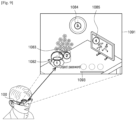
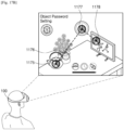
- FIG. 1 is a diagram illustrating an example of a method of operating a device, according to an embodiment.
- a device 100 may be implemented using, for example, and without limitation, a head mounted display (HMD).
- HMD head mounted display
- An HMD may be mounted on the head of a user and may display an image right in front of the eyes of the user.
- the HMD according to an embodiment may be realized in various types.
- the HMD may have, the form of, for example, and without limitation, at least one selected from goggles, eyeglasses, a helmet, a visor, or the like, but is not limited thereto.
- the device 100 of FIGS. 2, 3 , 4 and 5 may provide an augmented reality (AR) image.
- AR may refer, for example, to a technology displaying a three-dimensional (3D) virtual image realized via computer graphics and overlaid on a real space seen by the eyes of a user.
- a user may view a real surrounding space within the field of view of the user while wearing the HMD 100 on his or her head.
- an image 1001 recognized by the HMD 100 may be a scene 1000 of an actual surrounding space in the field of view of the user wearing the HMD 100.
- the HMD 100 may perform a pre-set task in correspondence with the certain object.
- the HMD 100 may, for example, pre-set an object existing in an actual space as a password in correspondence with a task that needs a password, and thus may perform the task with only a user's action of looking at the object set with the password.
- the movie playback application may be executed via a user's action of looking at the clock.
- the game application may be executed via a user's action of sequentially looking at the picture frame and the sofa.
- FIG. 1 is a diagram illustrating an example embodiment, and thus the disclosure is not limited thereto.
- FIGS. 2 and 3 illustrate a case where the HMD 100 is in the form of eyeglasses, but it will be understood that the disclosure is not limited thereto, and that the HMD 100 may be realized by any type of suitable device.
- the HMD 100 may include a frame 101, a lens 102, a power supply 103, a display 111, an audio output interface (e.g., including audio output circuitry) 112, a processor (e.g., including processing circuitry) 120, a user input interface (e.g., including input interface circuitry) 130, a camera 161, and a depth sensor 154. All of the components illustrated in FIG. 2 are not essential components of the HMD 100. More or less components than those illustrated in FIG. 2 may be included in the HMD 100. According to an embodiment, the HMD 100 may not, for example, include the lens 102.
- Some of the components of the HMD 100 may be built in the HMD 100, or the other components may be mounted on the exterior of the HMD 100.
- the power supply 103 and the processor 120 may be built in the HMD 100.
- the display 111, the audio output interface 112, the user input interface 130, the camera 161, and the depth sensor 154 may be mounted on the exterior of the HMD 100.
- the components built in the HMD 100 and the components mounted on the exterior of the HMD 100 are not limited to those described above.
- the frame 101 may be formed of a material such as, for example, and without limitation, plastic and/or metal, and may include wiring that connects the components of the HMD 100 to one another.
- the frame 101 may include a connection member (not shown) and may be constructed such that at least a portion of the frame 101 is bendable.
- the HMD 100 may further include an elastic band such that the HMD 100 may be fixed to the head of the user regardless of the size of the head of the user.
- the frame 101 may, for example, be constructed such that the lens 102 is detachable from the frame 101.
- the lens 102 may be formed of, for example, and without limitation, a transparent material that enables the user to see the actual space via the lens 102.
- the lens 102 may be formed, for example, and without limitation of glass and/or plastic, such as polycarbonate, but embodiments are not limited thereto.
- the lens 102 may include, for example, and without limitation, at least one of a light-reflection and antidazzle coating, an antifogging coating, an ultraviolet (UV)-block coating, or the like.
- the display 111 may, for example, replace the lens 102 or a portion of the lens 102.
- the display 111 may display the virtual image within a region thereof corresponding to the viewing angle of the user.
- the viewing angle of the user may refer, for example, to an angle or range within which the user is able to recognize an object without moving his or her head or pupils when the user is keeping eyes forward.
- the viewing angle of the user may be, but is not limited to, 45 degrees in each of upward and downward directions and 90 degrees in each of left and right directions.
- the display 111 may overlap a virtual image representing an object corresponding to the eyes of the user from among the plurality of objects included in the surrounding image, on the surrounding image, and display a result of the overlapping, under the control of the processor 120.
- the display 111 may overlap a virtual image related with a password input on the surrounding image and display a result of the overlapping, under the control of the processor 120.
- the display 111 may overlap a virtual image related with a password input and display a result of the overlapping, under the control of the processor 120.
- the display 111 may overlap a virtual image related with a password input and display a result of the overlapping, under the control of the processor 120.
- the audio output interface 112 may, for example, be detachable from the HMD 100. In this case, the user of the HMD 100 may selectively mount the audio output interface 112 on his or her ears.
- the user input interface 130 may include various user input circuitry and receives a user input.
- the user input may include, for example, and without limitation, a command, a request, or the like, from a user to the HMD 100 to start or conclude a certain operation.
- the user input interface 130 may include, for example, and without limitation, user input circuitry including a bending sensor for receiving a bending input.
- the bending input may refer, for example, to an input of a user bending a portion of the HMD 100 or the whole HMD 100 in order to control the HMD 100.
- the HMD 100 may sense, for example, and without limitation, a bending location (coordinate value), a bending direction, a bending angle, a bending speed, the number of times being bent, a point of time when bending occurs, a period of time during which bending is maintained, or the like, using a bending sensor.
- the user input interface 130 may receive multiple inputs.
- Multiple inputs may refer, for example, to a combination of at least two input methods.
- the HMD 100 may receive a touch input and a motion input from the user, receive a touch input and a voice input from the user, or the like.
- the HMD 100 may receive, for example, and without limitation, a touch input and an eyeball input from the user.
- the eyeball input may refer, for example, to an input of a user adjusting eye blinking, a staring location, an eyeball movement speed, or the like, in order to control the HMD 100.
- the HMD 100 may further include a microphone (not shown).
- the microphone may receive, for example, a voice of the user and sounds of a surrounding environment of the HMD 100.
- the camera 161 may, for example, and without limitation, be a camera for use in smartphones, a small camera such as a webcam, or the like.
- the camera 161 may, for example, be mounted on a location adjacent to an eye of the user to thereby capture an image that is similar to an image recognized via the eyes of the user.
- the depth sensor 154 may obtain the depth value of the input instrument according to various methods.
- the depth sensor 154 may measure the depth value using, for example, and without limitation, at least one of a time of flight (TOF) method, a stereoscopic vision method, a structured light pattern method, or the like.
- TOF time of flight
- the TOF method may refer, for example, to a method of measuring a distance to an object by analyzing a time period during which light is reflected by the object and returns.
- an infrared light-emitting diode LED
- an infrared camera measures a time period during which light is reflected by an object and returns.
- the depth sensor 154 may include an infrared LED and an infrared camera.
- the depth sensor 154 may photograph distance information in the form of a moving picture by repeating emission and reception of light several times per second.
- the depth sensor 154 may generate a depth map representing distance information with brightness or a color of each pixel.
- the stereoscopic vision method may refer, for example, to a method of photographing a stereoscopic effect of an object using two cameras.
- the depth sensor 154 may include two cameras.
- the depth sensor 154 may calculate (determine) the distance, based on the principle of triangulation, using information about a difference between images respectively viewed by the two cameras.
- a human being feels a stereoscopic effect via a difference between images respectively entering his or her left eye and right eye, and the depth sensor 154 measures the distance according to a method that is similar to the principle of human eyes. For example, when the distance is short, a difference between images captured by two cameras is big, and, when the distance is long, the difference between images captured by two cameras is small.
- a distance to an object is measured by projecting light having a pattern onto the object and analyzing a location of the pattern on the surface of the object.
- the depth sensor 154 generally projects a straight-line pattern or a dot pattern onto an object, and the pattern varies according to unevenness of the object.
- the structured light pattern method may, for example, be referred to as a structure in which one of two cameras for use in a stereoscopic vision method is replaced by a light projector.
- the depth sensor 154 may calculate a depth map in real time by analyzing, using an algorithm, a location of a pattern obtained by light emitted by an infrared projector and formed on the surface of an object.
- the camera 161 and the depth sensor 154 may be independent sensors. According to another embodiment, the camera 161 and the depth sensor 154 may be integrated into a single sensor.
- the HMD 100 may further include various sensors in addition to the camera 161 and the depth sensor 154.
- the HMD 100 may include sensors for sensing a motion input of the user.
- the motion input may refer, for example, to a motion that the user applies to the HMD 100 in order to control the HMD 100.
- the motion input may be an input of the user rotating the HMD 100, inclining the HMD 100, or moving the HMD 100 horizontally or vertically.
- the HMD 100 may sense a motion input that is preset by the user, using, for example, and without limitation, an acceleration sensor, a tilt sensor, a gyro sensor, a 3-axis magnetic sensor, or the like.
- the HMD 100 may determine whether the user is wearing the HMD 100.
- the HMD 100 may determine whether the user is wearing the HMD 100, using a sensor included in the HMD 100 (for example, and without limitation, at least one of a temperature sensor, a pressure sensor, an illumination sensor, a proximity sensor, an iris recognition sensor, an atmospheric pressure sensor, or the like). For example, when a value measured by a temperature sensor or pressure sensor attached to a nose pad or temple of the HMD 100 implemented using eyeglasses is equal to or greater than a critical value, the HMD 100 may determine that the user is wearing the HMD 100. When the HMD 100 succeeds in recognizing the iris of the user using an iris recognition sensor, the HMD 100 may determine that the user is wearing the HMD 100.
- a sensor included in the HMD 100 for example, and without limitation, at least one of a temperature sensor, a pressure sensor, an illumination sensor, a proximity sensor, an iris recognition sensor, an atmospheric pressure sensor, or the like.
- a sensor included in the HMD 100 for example, and without limitation, at least one of a temperature
- the HMD 100 may determine that the user is wearing the HMD 100.
- the HMD 100 may output a sound signal via the speaker and may obtain a reflected echo signal via the microphone.
- the HMD 100 may determine whether the user is wearing the HMD 100, using information about the echo signal.
- the HMD 100 may sense eye tracking information of the user (for example, and without limitation, pupil recognition information, information of the number of times the eyes blink, information of an eye-blinking speed, information of an eye direction, or the like) using at least one sensor included in the HMD 100.
- eye tracking information of the user for example, and without limitation, pupil recognition information, information of the number of times the eyes blink, information of an eye-blinking speed, information of an eye direction, or the like.
- the HMD 100 may capture an image of the eyes of the user at regular intervals by using an image sensor, and may detect the pupils of the user via an edge analysis of the captured image of the eyes.
- the lens 102 of the HMD 100 may execute a function of the display 111.
- the lens 102 may include, for example, and without limitation, a transparent display or a semi-transparent display, or the like.
- the lens 102 may, for example, include the same material as a material of the at least one optical waveguide (for example, a prism), an organic light emitting diode (OLED) display, a liquid crystal display (LCD), or the like, but the material of the lens 102 is not limited thereto.
- FIGS. 2 and 3 illustrate an example where the HMD 100 has the form of eyeglasses.
- the HMD 100 may be attached to a helmet structure or may be transformed into goggles, or the like.
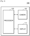
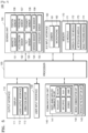
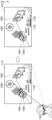
- FIGS. 4 and 5 are block diagrams illustrating an example device 100 according to an example embodiment.
- the device 100 may include the display 111, the camera 161, and the processor 120. However, all of the illustrated components are not essential. The device 100 may be implemented by more or less components than those illustrated in FIGS. 4 and 5 .
- the device 100 may further include an output interface (e.g., including output circuitry) 110, the user input interface (e.g., including input circuitry) 130, a communication unit (e.g., including communication circuitry)140, a sensing unit (e.g., including sensor circuitry) 150, an audio/video (A/V) input interface (e.g., including A/V input circuitry) 160, and a memory 170, in addition to the display 111, the camera 161, and the processor 120.
- the sensing unit 150 may be expressed as a sensor unit.
- An output interface 110 includes various output circuitry and outputs an audio signal, a video signal, a vibration signal, or the like and may include, for example, and without limitation, the display 111, the audio output interface 112, a vibration motor 113, or the like.
- the display 111 may display information that is processed by the device 100.
- the display 111 may display a surrounding image of the device 100.
- the display 111 may display a virtual image related with an object included in the surrounding image.
- the display 111 may, for example, and without limitation, display an image in the form of AR, MR, VR, or the like.
- the display 111 When the display 111 forms a layer structure together with a touch pad to provide a touch screen, the display 111 may be used as an input device as well as an output device.
- the display 111 may include, for example, and without limitation, at least one of an LCD, a thin film transistor-LCD (TFT-LCD), an OLED, a flexible display, a 3D display, an electrophoretic display, or the like.
- the device 100 may include two or more displays 111.
- the audio output interface 112 may include various output circuitry and outputs audio data that is received from the communication unit 140 or stored in the memory 170.
- the audio output interface 112 may also output an audio signal (for example, a call signal receiving sound, a message receiving sound, a notification sound) related with a function of the device 100.
- the audio output interface 112 may include various output circuitry, such as, for example, and without limitation, a speaker, a buzzer, or the like.
- the processor 120 may include various processing circuitry and typically controls all operations of the device 100.
- the processor 120 may control the output interface 110, the user input interface 130, the communicator 140, the sensing unit 150, and the A/V input interface 160 by executing the programs stored in the memory 170.
- the processor 120 may obtain the surrounding image of the device 100 via the camera 161.
- the processor 120 may recognize the eyes of a user who is wearing the device 100.
- the processor 120 may determine one or more objects corresponding to the eyes of the user from among a plurality of objects included in the surrounding image.
- the processor 120 may perform a preset task corresponding to the determined one or more objects.
- the processor 120 may detect the plurality of objects included in the obtained surrounding image, and may control the display 111 to overlap virtual icons indicating the detected objects on the surrounding image such that the virtual icons may be mapped with the detected objects, and display a result of the overlapping.
- the processor 120 may determine whether the object corresponding to the eyes of the user corresponds to an object set as a password, based on at least one of the form, the shape, and the color of the object corresponding to the eyes of the user, and may perform a task corresponding to the password.
- the processor 120 may determine an order in which the user looks at one or more objects corresponding to the eyes of the user, and perform a preset task corresponding to the determined order.
- the processor 120 may sense a hand gesture of the user and perform a preset task corresponding to the hand gesture.
- the processor 120 may control the display 111 to overlap a virtual image related with a password input on the surrounding image and display a result of the overlapping.
- the processor 120 may store, as a password, the order of looking at the one or more objects.
- the processor 120 may store the hand gesture of the user as a password.
- the communication unit 140 may include various communication circuitry that enables the HMD 100 to communicate with another device (not shown) or a server (not shown).
- the communicator 140 may include various communication circuitry included in various units or modules, such as, for example, and without limitation, a short-range wireless communication unit 141, a mobile communication unit 142, a broadcastreception unit 143, or the like.
- the short-range wireless communication unit 141 may include, but is not limited to, a Bluetooth communicator, a Bluetooth Low Energy (BLE) communicator, a near field communication (NFC) unit, a wireless local area network (WLAN) (e.g., Wi-Fi) communicator, a ZigBee communicator, an infrared Data Association (IrDA) communicator, a Wi-Fi direct (WFD) communicator, an ultra wideband (UWB) communicator, an Ant+ communicator, and the like.
- BLE Bluetooth Low Energy
- NFC near field communication
- WLAN wireless local area network
- IrDA infrared Data Association
- WFD Wi-Fi direct
- UWB ultra wideband
- the mobile communication unit 142 may exchange a wireless signal with at least one selected from a base station, an external terminal, and a server on a mobile communication network.
- Examples of the wireless signal may include a voice call signal, a video call signal, and various types of data according to text/multimedia messages transmission.
- the broadcast reception unit 143 may receive, for example, a broadcast signal and/or broadcasting-related information from an external source via a broadcasting channel.
- the broadcasting channel may be a satellite channel, a ground wave channel, or the like.
- the HMD 100 may not include the broadcasting reception unit 143.
- the sensing unit 150 may include various sensors including various sensing circuitry and sense the status of the HMD 100, the status of the surrounding of the HMD 100, the status of the user who wears the HMD 100, or the like, and may transmit the sensed information to the processor 120.
- the sensing unit 150 may sense a motion of the user and may output a signal related with the motion of the user to the processor 120.
- the signal may be an electrical signal.
- the sensing unit 150 may include, but is not limited thereto, at least one selected from a magnetic sensor 151, an acceleration sensor 152, a tilt sensor 153, the depth sensor 154, a gyroscope sensor 155, a position sensor (e.g., a GPS) 156, an atmospheric pressure sensor 157, a proximity sensor 158, an optical sensor (e.g., RGB) 159, or the like.
- the sensing unit 150 may include, for example, and without limitation, a temperature sensor, an illumination sensor, a pressure sensor, an iris recognition sensor, or the like. Functions of most of the sensors would be understood by one of ordinary skill in the art in view of their names and thus detailed descriptions thereof will not be provided herein.
- the A/V input interface 160 may include various A/V input circuitry that inputs an audio signal or a video signal, and may include, for example, and without limitation, the camera (image sensor) 161, a microphone 162, or the like.
- the camera (image sensor) 161 may obtain an image frame, such as a still image or a moving picture, in a video call mode or a photography mode.
- An image captured via the camera (image sensor) 161 may be processed by the processor 120 or a separate image processor (not shown).
- the image frame obtained by the camera (image sensor) 161 may be stored in the memory 170 or transmitted to the outside via the communication unit 140. Two or more cameras (image sensors) 161 may be included according to embodiments of the HMD 100.
- the microphone 162 may include various circuitry that receives an external audio signal and converts the external audio signal into electrical audio data. For example, the microphone 162 may receive an audio signal from an external device or a speaking person. The microphone 162 may use various noise removal algorithms in order to remove noise that is generated while receiving the external audio signal.
- the memory 170 may include, for example, and without limitation, at least one type of storage medium selected from among a flash memory type, a hard disk type, a multimedia card micro type, a card type memory (for example, a secure digital (SD) or extreme digital (XD) memory), a random access memory (RAM), a static random access memory (SRAM), a read-only memory (ROM), an electrically erasable programmable ROM (EEPROM), a programmable ROM (PROM), magnetic memory, a magnetic disk, an optical disk, or the like.
- the HMD 100 may operate a web storage or a cloud server on the internet which performs a storage function of the memory 170.
- the programs stored in the memory 170 may be classified into a plurality of modules according to their functions, for example, and without limitation, a user interface (UI) module 171, a speech-to-text (STT) module 172, a notification module 173, an image processing module 174.
- UI user interface
- STT speech-to-text
- the STT module 172 may convert a voice included in multimedia content into a text to generate a transcript corresponding to the multimedia content.
- the image processing module 174 may obtain type information of an object included in an image obtained via analysis of the captured image, and shape information, form information, color information, and the like of the object.
- FIGS. 2, 3 , 4 and 5 illustrate an example embodiment, and it will be understood that the disclosure is not limited thereto.
- the device 100 may obtain a surrounding image of the device 100 via the camera 161.
- the camera 161 when the user wears the device 100, the camera 161 may be positioned adjacent to an eye of the user, and thus may capture an image that is similar to a scene recognized via the eyes of the user.
- the device 100 may recognize eyes of the user that sequentially look at a plurality of objects included in the surrounding image.
- the device 100 may include an eye tracking camera (not shown) that faces the user.
- the eye tracking camera may include an infrared camera.
- the eye tracking camera may detect user's eyes by tracking the irises of the user.
- the device 100 may determine an object corresponding to the eyes of the user from among the plurality of objects included in the surrounding image.
- the device 100 may recognize the object 1082 being observed by the user as a password input.
- an object 1082 for example, a kettle
- the device 100 may recognize the object 1084 being observed by the user as a password input.
- an object 1084 for example, a clock
- the device 100 may control the display 111 to overlap virtual images 1105 and 1106 representing the objects determined to correspond to the eyes of the user, on the surrounding images 1101 and 1102, and display a result of the overlapping.
- the device 100 may recognize the object 1085 being observed by the user as a password input.
- an object 1085 for example, a picture frame
- the device 100 may overlap virtual images 1105, 1106, and 1107 representing the objects determined to correspond to the eyes of the user, on the surrounding image 1111, and may display a result of the overlapping. Accordingly, the user may check an object input as a password.
- the device 100 may recognize eyes that sequentially look at the plurality of objects 1082, 1084, and 1085.
- the device 100 may provide a UI for requesting an object password to be input.
- the device 100 may overlap a virtual image for requesting selection of an object set as a password, on a surrounding image obtained by the camera 161, and display a result of the overlapping. For example, referring to FIG. 9 , the device 100 may display a virtual image 1093 for requesting an object password to be input.
- the device 100 may recognize, as a password, an object determined to correspond to user's eyes, in response to the UI for requesting an object password to be input.
- the device 100 may overlap a virtual image related with a password input on the surrounding image and display a result of the overlapping.
- a method in which that the device 100 senses that the user is wearing the device 100 has been described above with reference to FIG. 2 , and thus a detailed description thereof will not be provided.
- the device 100 may overlap a virtual image for requesting selection of an object set as a password, on the surrounding image, and display a result of the overlapping.
- the device 100 may provide an interface for requesting a password input. For example, when the user enters a space in which an object password for executing a game application has been set, the device 100 may provide a UI for a password input.
- the device 100 may overlap a virtual image for requesting selection of an object set as a password, on the surrounding image, and display a result of the overlapping.
- a predetermined user input for example, a user voice command
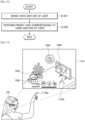
- the device 100 may perform a preset task corresponding to a plurality of objects and an order of looking at the plurality of objects.
- the device 100 may store the plurality of objects as a password needed to perform a certain task. As the device 100 according to an embodiment recognizes that the user looks at the plurality of objects in a certain order, the device 100 may determine that a password has been input. When it is determined that an object corresponding to the eyes of the user is identical with an object pre-stored as a password, the device 100 may perform a task (for example, execution of a music playback application) stored in correspondence with the password.
- a task for example, execution of a music playback application
- a music playback application set in correspondence with the password may be executed.
- the device 100 may display a graphic image 1112 related with music playback on the display 111.
- the device 100 may determine whether an object corresponding to the eyes of the user corresponds to an object set as a password, based, for example, and without limitation, on at least one of the form, the shape, and the color of the object, and may perform a task corresponding to the password.
- the device 100 may determine whether a recognized object is recognized as an object that is the same as an object preset as a password within a preset recognition error range.
- a recognition error according to photographing conditions for example, a distance between the camera 161 and an object, a photographing angle therebetween, and surrounding illuminance
- the device 100 may calculate (determine) an allowable recognition error range using an image processing algorithm and may determine an object recognized within the calculated allowable recognition error range as an identical object.
- FIG. 7 is a flowchart illustrating example display of a virtual image, according to an example embodiment.
- the device 100 may obtain a surrounding image of the device 100, via a camera.
- Operation S701 is the same as operation S601 of FIG. 6 described above, and thus a detailed description thereof will not be repeated here.
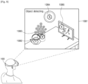
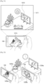
- the device 100 may detect a plurality of objects from the obtained surrounding image of the device 100.
- the device 100 may detect a plurality of objects 1082, 1083, 1084, and 1085 from the surrounding image 1081 obtained by the camera 161, using an image processing algorithm.
- the plurality of objects 1082, 1083, 1084, and 1085 may be objects existing in an actual space, such as a kettle 1082, a flowerpot 1083, a clock 1084, and a picture frame 1085, but embodiments are not limited thereto.
- the device 100 may control the display 111 to overlap virtual icons indicating the detected objects on the surrounding image such that the virtual icons may be mapped with the detected objects and display a result of the overlapping.
- the device 100 may overlap a virtual icon (for example, and without limitation, a number icon, a dotted line, or a symbol icon, such as an arrow) indicating each of the objects included in a surrounding image being observed by the user, on the surrounding image such that the virtual icons may be mapped with the objects, and display a result of the overlapping.
- a virtual icon for example, and without limitation, a number icon, a dotted line, or a symbol icon, such as an arrow
- respective number icons indicating the plurality of objects 1082, 1083, 1084, and 1085 included in the surrounding image 1081 looked at by the user currently wearing the device 100 may be displayed to be recognized by being mapped with the objects 1082, 1083, 1084, and 1085.
- a virtual icon or a virtual image may, for example, be a 3D graphic image, and may be displayed while being overlapped on an actual image such that the virtual icon or the virtual image may be recognized seamlessly within the setting of an actual space.
- the user may check virtual icons (for example, number icons) (see FIG. 8 ) displayed by being mapped with the plurality of objects included in the surrounding image 1081 via the display 111 and may perform a password input by looking at one or more of the identified plurality of objects.
- virtual icons for example, number icons
- the device 100 may overlap a virtual image representing an object corresponding to the eyes of the user from among the plurality of objects included in the surrounding image, on the surrounding image, and display a result of the overlapping.
- the device 100 may generate and display a virtual image such that the user may check the object recognized as a password input.
- the device 100 may overlap the virtual image 1106 representing the object 1084 (e.g., a clock) determined to correspond to the eyes of the user, on the surrounding image 1102, and display a result of the overlapping.
- the device 100 may overlap the virtual image 1107 representing the object 1085 (e.g., a picture frame) determined to correspond to the eyes of the user, on the surrounding image 1111, and display a result of the overlapping.
- FIGS. 6, 7 , 8 , 9 , 10 and 11 illustrate an example embodiment, and thus the disclosure is not limited thereto.
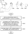
- the hand movement may be included in a surrounding image obtained by the device 100 via the camera 161.
- the device 100 may sense the hand movement of the user included in the surrounding image.
- the device 100 may perform a preset task corresponding to the hand gesture of the user.
- the device 100 when the device 100 determines that the sensed hand gesture of the user corresponds to a preset password, the device 100 may perform a preset task corresponding to the password.
- the device 100 may set a combination of a plurality of hand gestures as a password.
- the device 100 may set, as a password, an order in which a plurality of hand gestures are sequentially made.
- the device 100 may set a combination of a certain object and a certain hand gesture as a password, but the disclosure is not limited thereto.
- FIGS. 12, 13 and 14 illustrate an example embodiment, and thus the disclosure is not limited thereto.
- the device 100 may receive an input of selecting a task corresponding to a password.
- a task may be, but is not limited to, execution of a certain application (for example, a game application or a music playback application) or release of a lock screen.
- a certain application for example, a game application or a music playback application
- the device 100 may display, on the display 111, a UI screen 1161 including a list of tasks.
- the device 100 may set a music playback application 1162 in response to a user input.
- the device 100 may store the object being observed as the password corresponding to the selected task.
- one or more objects within an actual space being observed by the user currently wearing the device 100 may be set as a password.
- a combination of the plurality of objects 1172, 1173, and 1174 may be set as a password.
- the device 100 may store the order of looking at the one or more objects as a password.
- a combination of the looked-at objects 1175, 1177, and 1178 and the order of looking at the objects 1175, 1177, and 1178 may be set as a password.
- the device 100 may store the hand gesture of the user as a password.
- the device 100 may sense a hand gesture 1185b of the user from a surrounding image 1181 of the sight of the user obtained via the camera 161.
- the device 100 may store a combination of an object 1182 (for example, a clock) recognized in relation to the hand gesture 1185b of the user and the hand gesture 1185b of the user, as a password.
- an object 1182 for example, a clock
- the device 100 may provide a virtual graphic image such that the user may check that the object 1182 has been selected. For example, referring to FIG. 18 , as the device 100 senses the hand gesture 1185b of the user, the device 100 may display a virtual image 1183 on a display such that the virtual image 1183 may be mapped with the hand gesture 1185b of the user.
- the order of operations S1501 through S1504 of FIG. 15 may be changed, and a password according to execution of at least one operation thereof may be set.
- a password may be set according to a combination of one or more of the operations S1502 through S1504.
- a plurality of objects may be stored as a password, or a combination of one or more objects and a hand gesture of the user may be stored as a password.
- a combination of a plurality of hand gestures may be stored as a password, but embodiments are not limited thereto.
- FIGS. 15 , 16 , 17A , 17B and 18 illustrate an example embodiment, and thus the disclosure is not limited thereto.
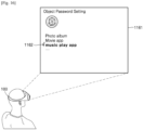
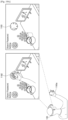
- FIGS. 19A and 19B are diagrams illustrating an example of setting a password using a hand gesture of a user according to an example embodiment.
- the device 100 may enter a menu for setting a password.
- the device 100 may display a virtual graphic icon 1192 for entering a password setting menu.
- the virtual graphic icon 1192 may be provided together with a virtual arrow image such that the user may intuitively recognize that the virtual graphic icon 1192 is to be rotated clockwise to enter the menu.
- the device 100 may provide a dialtype menu icon 1193 as a virtual graphic image.
- the device 100 may select a menu, based on a hand gesture input of rotating the dialtype menu icon 1193.
- the user may perform an input, such as menu entering or menu section, for setting a password via a hand gesture input.
- the device 100 when the device 100 senses that the user sequentially makes one or more hand gestures, the device 100 may store a sequential combination of the hand gestures as a password.
- the device 100 may store a combination of various hand gestures 1196a, 1196b, 1196c, and 1196d of the user as a password.
- the device 100 may set one hand gesture as a password. According to an embodiment, the device 100 may set a plurality of hand gestures as a password, regardless of an order thereof.
- FIGS. 19A and 19B illustrate an example embodiment, and thus the disclosure is not limited thereto.
- FIG. 20 is a flowchart illustrating an example method of operating a device, according to another example embodiment.
- FIGS. 21 and 22 are diagrams for illustrating example recognition of an object corresponding to a user input, according to another example embodiment. The flowchart of FIG. 20 will now be described with reference to FIGS. 21 and 22 .
- the device 100 may, for example, and without limitation, be a mobile phone.
- the device 100 may obtain a surrounding image of the device 100, via the camera 161.
- the surrounding image of the device 100 may be obtained via the camera 161.
- the device 100 may receive a user input of selecting the person 1233 being displayed on the display 111.
- the device 100 may capture an image by applying the preset photographing filter value.
- a computer readable medium can be any recording medium which can be accessed by the computer and includes all volatile/non-volatile and removable/non-removable media.
- Examples of the computer readable recording medium include, but are not limited to, magnetic storage media (e.g., ROM, floppy disks, hard disks, etc.), optical recording media (e.g., CD-ROMs, or DVDs), etc. Further, the computer readable medium may include all computer storage and communication media.
- unit when used in this disclosure may be used to refer to a unit in which at least one function or In operation is performed, and may be implemented as hardware, software, or a combination of hardware and software.
Landscapes
- Engineering & Computer Science (AREA)
- Theoretical Computer Science (AREA)
- General Engineering & Computer Science (AREA)
- Physics & Mathematics (AREA)
- General Physics & Mathematics (AREA)
- Human Computer Interaction (AREA)
- Computer Hardware Design (AREA)
- Computer Security & Cryptography (AREA)
- Software Systems (AREA)
- Multimedia (AREA)
- Computer Graphics (AREA)
- User Interface Of Digital Computer (AREA)
Claims (12)
- Gerät (100), das so konfiguriert ist, dass es einen Augmented Reality-Dienst (AR) bereitstellt, wobei das Gerät (100) Folgendes umfasst:eine Anzeige (111);eine Kamera (161); undeinen Prozessor (120), der dazu konfiguriert ist:die Kamera (161) zu steuern, um ein Umgebungsbild der Umgebung des Geräts (100) zu erhalten;die Anzeige (111) zu steuern, um das erhaltene Umgebungsbild anzuzeigen;eine Vielzahl realer Objekte zu erkennen, die in dem erhaltenen Umgebungsbild enthalten sind;eine Vielzahl von virtuellen Symbolen anzuzeigen, die der Vielzahl von realen Objekten zugeordnet sind, die im Umgebungsbild erkannt wurden, und die Vielzahl von erkannten realen Objekten anzeigen, wobei sie die Vielzahl von erkannten realen Objekten überlappen, sodass der Benutzer die Vielzahl von realen Objekten wahrnimmt, die durch die Vielzahl von virtuellen Symbolen angezeigt werden;eine Vielzahl realer Objekte zu erkennen, die nacheinander von den Augen eines Benutzers beobachtet werden, der das Gerät trägt; unddie Vielzahl virtueller Symbole, die die Vielzahl realer Objekte darstellen, auf die der Benutzer nacheinander auf dem umgebenden Bild blickt, entsprechend der Reihenfolge, in der der Benutzer auf die Vielzahl realer Objekte geblickt hat;zu bestimmen, ob die erkannte Vielzahl realer Objekte einer Vielzahl von Objekten entspricht, die als Passwort voreingestellt sind;basierend auf der Bestimmung, dass die erkannte Vielzahl realer Objekte der Vielzahl von Objekten entspricht, die als Passwort voreingestellt sind, eine voreingestellte Aufgabe auszuführen, die der Vielzahl realer Objekte und einer Reihenfolge entspricht, in der die Vielzahl realer Objekte beobachtet wird.
- Gerät (100) nach Anspruch 1, wobei der Prozessor (120) ferner dazu konfiguriert ist, eine Anzeige (111) so zu steuern, dass sie auf das Umgebungsbild ein virtuelles Bild überlagert, das ein von den Augen des Benutzers wahrgenommenes Objekt aus der Vielzahl von realen Objekten darstellt, die im Umgebungsbild enthalten sind, und ein Ergebnis der Überlagerung anzuzeigen.
- Gerät (100) nach Anspruch 1, wobei der Prozessor (120) ferner dazu konfiguriert ist, das Gerät (100) so zu steuern, dass es eine Handgeste des Benutzers erkennt und eine voreingestellte Aufgabe entsprechend der Handgeste ausführt.
- Gerät (100) nach Anspruch 1, wobei der Prozessor (120) ferner dazu konfiguriert ist, eine Anzeige (111) so zu steuern, dass sie auf das umgebende Bild ein virtuelles Bild überlagert, das mit einer Passworteingabe in Zusammenhang steht, wenn erkannt wird, dass das Gerät vom Benutzer getragen wird, und ein Ergebnis der Überlagerung anzuzeigen.
- Gerät (100) nach Anspruch 1, wobei der Prozessor (120) ferner dazu konfiguriert ist, eine Anzeige (111) so zu steuern, dass sie auf das Umgebungsbild ein virtuelles Bild überlagert, das mit einer Passworteingabe in Zusammenhang steht, wenn das über die Kamera (161) erhaltene Umgebungsbild des Geräts (100) einem vorab gespeicherten Bild entspricht, und ein Ergebnis der Überlagerung anzuzeigen.
- Gerät (100) nach Anspruch 1, wobei der Prozessor (120) ferner dazu konfiguriert ist, eine Anzeige (111) zu steuern, um auf das umgebende Bild ein virtuelles Bild zu überlagern, das mit einer Kennworteingabe auf der Grundlage einer vorgegebenen Benutzereingabe in Zusammenhang steht, und ein Ergebnis der Überlagerung anzuzeigen.
- Gerät (100) nach Anspruch 1, wobei der Prozessor (120) ferner dazu konfiguriert ist:eine Eingabe zu empfangen, die eine Aufgabe auswählt, die einem Passwort entspricht; unddas beobachtete Objekt als das Passwort zu speichern, das der ausgewählten Aufgabe entspricht, während der Benutzer für einen vorbestimmten Zeitraum oder länger ein Objekt beobachtet, das im Umgebungsbild enthalten ist.
- Gerät (100) nach Anspruch 7, wobei der Prozessor (120) dazu konfiguriert ist, als Passwort eine Reihenfolge zu speichern, in der ein oder mehrere Objekte beobachtet werden, wenn der Benutzer nacheinander ein oder mehrere Objekte beobachtet, die im Umgebungsbild enthalten sind.
- Gerät (100) nach Anspruch 7, wobei der Prozessor (120) dazu konfiguriert ist, als Passwort eine Handbewegung des Benutzers zu speichern, wenn die Handbewegung des Benutzers erfasst wird.
- Gerät (100) nach Anspruch 1, wobei die voreingestellte Aufgabe mindestens eines von Ausführen einer Anwendung und Entsperren des Geräts (100) umfasst.
- Verfahren zum Betreiben eines Geräts (100), das so konfiguriert ist, dass es einen Augmented Reality-AR-Dienst bereitstellt, wobei das Verfahren Folgendes umfasst:Erfassen eines Umgebungsbilds der Umgebung des Geräts über eine Kamera (161);Anzeigen des erfassten Umgebungsbilds;Erkennen einer Vielzahl realer Objekte, die in dem erfassten Umgebungsbild enthalten sind;Anzeigen einer Vielzahl virtueller Symbole, die der Vielzahl realer Objekte zugeordnet sind, die im Umgebungsbild erkannt wurden, und die Vielzahl erkannter realer Objekte angeben, wobei sie die Vielzahl erkannter realer Objekte überlappen, so dass der Benutzer die Vielzahl realer Objekte wahrnimmt, die durch die Vielzahl virtueller Symbole angegeben werden;Erkennen einer Vielzahl realer Objekte, die nacheinander von den Augen eines Benutzers beobachtet werden, der das Gerät trägt; undAnzeigen der Vielzahl virtueller Symbole, die die Vielzahl realer Objekte darstellen, auf die der Benutzer nacheinander auf dem umgebenden Bild blickt, und zwar in der Reihenfolge, in der der Benutzer auf die Vielzahl realer Objekte geblickt hat;Bestimmen, ob die erkannte Vielzahl realer Objekte einer Vielzahl von Objekten entspricht, die als Passwort voreingestellt sind;basierend auf dem Bestimmen, dass die erkannte Vielzahl realer Objekte der Vielzahl von Objekten entspricht, die als Passwort voreingestellt sind, Ausführen einer voreingestellten Aufgabe, die der Vielzahl realer Objekte und einer Reihenfolge entspricht, in der die Vielzahl realer Objekte beobachtet wird.
- Nicht flüchtiges, computerlesbares Aufzeichnungsmedium, auf dem ein Computerprogramm aufgezeichnet ist, das, wenn es von einem Computer ausgeführt wird, das Verfahren nach Anspruch 11 ausführt.
Applications Claiming Priority (2)
| Application Number | Priority Date | Filing Date | Title |
|---|---|---|---|
| KR1020180008413A KR20190089627A (ko) | 2018-01-23 | 2018-01-23 | Ar 서비스를 제공하는 디바이스 및 그 동작 방법 |
| PCT/KR2019/000979 WO2019147021A1 (en) | 2018-01-23 | 2019-01-23 | Device for providing augmented reality service, and method of operating the same |
Publications (3)
| Publication Number | Publication Date |
|---|---|
| EP3717992A1 EP3717992A1 (de) | 2020-10-07 |
| EP3717992A4 EP3717992A4 (de) | 2020-12-30 |
| EP3717992B1 true EP3717992B1 (de) | 2025-03-19 |
Family
ID=67298645
Family Applications (1)
| Application Number | Title | Priority Date | Filing Date |
|---|---|---|---|
| EP19743228.9A Active EP3717992B1 (de) | 2018-01-23 | 2019-01-23 | Vorrichtung zur bereitstellung eines dienstes für erweiterte realität und verfahren zum betrieb davon |
Country Status (5)
| Country | Link |
|---|---|
| US (1) | US20190227694A1 (de) |
| EP (1) | EP3717992B1 (de) |
| KR (1) | KR20190089627A (de) |
| CN (1) | CN111630477B (de) |
| WO (1) | WO2019147021A1 (de) |
Families Citing this family (21)
| Publication number | Priority date | Publication date | Assignee | Title |
|---|---|---|---|---|
| US11176751B2 (en) * | 2020-03-17 | 2021-11-16 | Snap Inc. | Geospatial image surfacing and selection |
| WO2021203110A1 (en) * | 2020-03-30 | 2021-10-07 | Citrix Systems, Inc. | Extended reality authentication |
| US11362825B2 (en) * | 2020-03-30 | 2022-06-14 | Citrix Systems, Inc. | Extended reality authentication |
| KR102845946B1 (ko) * | 2020-04-29 | 2025-08-13 | 삼성전자주식회사 | 증강 현실 장치 및 그 제어 방법 |
| CN111552076B (zh) * | 2020-05-13 | 2022-05-06 | 歌尔科技有限公司 | 一种图像显示方法、ar眼镜及存储介质 |
| KR20220047035A (ko) | 2020-10-08 | 2022-04-15 | 삼성전자주식회사 | 객체의 깊이를 측정하는 디바이스 및 방법 |
| US11847258B2 (en) | 2020-11-17 | 2023-12-19 | Samsung Electronics Co., Ltd. | Method for wireless connection in augmented reality environment and electronic device therefor |
| KR20220067128A (ko) * | 2020-11-17 | 2022-05-24 | 삼성전자주식회사 | 증강 현실 환경의 무선 연결 방법 및 이를 위한 전자 장치 |
| KR20220074652A (ko) * | 2020-11-27 | 2022-06-03 | 가온미디어 주식회사 | 복합 멀티 안테나 기반의 슬림형 xr 디바이스 및 그 제어 방법 |
| KR20220074643A (ko) * | 2020-11-27 | 2022-06-03 | 가온미디어 주식회사 | 슬림형 xr 디바이스 및 그 제어 방법 |
| KR102580559B1 (ko) | 2021-01-08 | 2023-09-21 | 한국전자통신연구원 | 시각적 정보를 이용한 통역 결과 제공 방법, 장치 및 시스템 |
| CN116888574A (zh) * | 2021-02-23 | 2023-10-13 | 苹果公司 | 共存会话中的数字助理交互 |
| EP4281854B1 (de) | 2021-02-23 | 2025-09-17 | Apple Inc. | Interaktionen eines digitalen assistenten in erweiterter realität |
| KR102721780B1 (ko) * | 2021-08-27 | 2024-10-24 | 엘아이지넥스원 주식회사 | Hmd 기반 ar 시스템을 위한 사물 터치 장치 및 방법 |
| US11874969B2 (en) * | 2021-09-15 | 2024-01-16 | Htc Corporation | Method for determining two-handed gesture, host, and computer readable medium |
| KR20230045928A (ko) * | 2021-09-29 | 2023-04-05 | 삼성전자주식회사 | 증강 현실 서비스를 제공하기 위한 전자 장치 및 그의 동작 방법 |
| EP4369075A4 (de) | 2021-09-29 | 2024-11-20 | Samsung Electronics Co., Ltd. | Elektronische vorrichtung zur bereitstellung eines dienstes für erweiterte realität und betriebsverfahren dafür |
| WO2023167039A1 (ja) * | 2022-03-03 | 2023-09-07 | 株式会社ソニー・インタラクティブエンタテインメント | 駆動制御システム、ヘッドマウントディスプレイ、及び駆動制御方法 |
| US12455954B2 (en) | 2022-08-03 | 2025-10-28 | Samsung Electronics Co., Ltd. | Apparatus and method for authenticating user in augmented reality |
| WO2024049178A1 (ko) * | 2022-09-02 | 2024-03-07 | 삼성전자주식회사 | 하나 이상의 외부 객체들 중 적어도 하나의 외부 객체의 표시를 제어하기 위한 전자 장치 및 방법 |
| EP4498664A4 (de) | 2022-09-02 | 2025-07-30 | Samsung Electronics Co Ltd | Elektronische vorrichtung und verfahren zur steuerung der anzeige von mindestens einem externen objekt zwischen einem oder mehreren externen objekten |
Citations (1)
| Publication number | Priority date | Publication date | Assignee | Title |
|---|---|---|---|---|
| US20170318019A1 (en) * | 2016-04-29 | 2017-11-02 | John C. Gordon | Gaze-based authentication |
Family Cites Families (11)
| Publication number | Priority date | Publication date | Assignee | Title |
|---|---|---|---|---|
| EP2503479B1 (de) * | 2011-03-21 | 2015-08-05 | BlackBerry Limited | Anmeldungsverfahren basierend auf der Blickrichtung |
| JP6289468B2 (ja) * | 2012-08-24 | 2018-03-07 | エンパイア テクノロジー ディベロップメント エルエルシー | バーチャルリアリティアプリケーション |
| JP2014092940A (ja) * | 2012-11-02 | 2014-05-19 | Sony Corp | 画像表示装置及び画像表示方法、並びにコンピューター・プログラム |
| US9996150B2 (en) * | 2012-12-19 | 2018-06-12 | Qualcomm Incorporated | Enabling augmented reality using eye gaze tracking |
| EP2887253A1 (de) * | 2013-12-18 | 2015-06-24 | Microsoft Technology Licensing, LLC | Benutzer-Authentifizierung über grafisches Augmented-Reality-Passwort |
| US20170186236A1 (en) * | 2014-07-22 | 2017-06-29 | Sony Corporation | Image display device, image display method, and computer program |
| KR20160033376A (ko) * | 2014-09-18 | 2016-03-28 | (주)에프엑스기어 | 시선에 의해 제어되는 헤드 마운트형 디스플레이 장치, 이의 제어 방법 및 이의 제어를 위한 컴퓨터 프로그램 |
| US10725533B2 (en) * | 2014-09-26 | 2020-07-28 | Intel Corporation | Systems, apparatuses, and methods for gesture recognition and interaction |
| CN107016270A (zh) * | 2015-12-01 | 2017-08-04 | 由田新技股份有限公司 | 结合脸部认证或手部认证的动态图形眼动认证系统、方法 |
| US10115205B2 (en) * | 2016-03-11 | 2018-10-30 | Facebook Technologies, Llc | Eye tracking system with single point calibration |
| US9871774B1 (en) * | 2016-09-29 | 2018-01-16 | International Business Machines Corporation | Secured file transfer management on augmented reality (AR) and virtual reality (VR) devices |
-
2018
- 2018-01-23 KR KR1020180008413A patent/KR20190089627A/ko not_active Ceased
-
2019
- 2019-01-23 CN CN201980009577.XA patent/CN111630477B/zh active Active
- 2019-01-23 US US16/254,948 patent/US20190227694A1/en not_active Abandoned
- 2019-01-23 WO PCT/KR2019/000979 patent/WO2019147021A1/en not_active Ceased
- 2019-01-23 EP EP19743228.9A patent/EP3717992B1/de active Active
Patent Citations (1)
| Publication number | Priority date | Publication date | Assignee | Title |
|---|---|---|---|---|
| US20170318019A1 (en) * | 2016-04-29 | 2017-11-02 | John C. Gordon | Gaze-based authentication |
Also Published As
| Publication number | Publication date |
|---|---|
| KR20190089627A (ko) | 2019-07-31 |
| WO2019147021A1 (en) | 2019-08-01 |
| EP3717992A1 (de) | 2020-10-07 |
| CN111630477B (zh) | 2024-11-22 |
| US20190227694A1 (en) | 2019-07-25 |
| CN111630477A (zh) | 2020-09-04 |
| EP3717992A4 (de) | 2020-12-30 |
Similar Documents
| Publication | Publication Date | Title |
|---|---|---|
| EP3717992B1 (de) | Vorrichtung zur bereitstellung eines dienstes für erweiterte realität und verfahren zum betrieb davon | |
| US10983593B2 (en) | Wearable glasses and method of displaying image via the wearable glasses | |
| US10114466B2 (en) | Methods and systems for hands-free browsing in a wearable computing device | |
| EP3011418B1 (de) | Virtuelle objektorientierung und -visualisierung | |
| US10009542B2 (en) | Systems and methods for environment content sharing | |
| KR102473259B1 (ko) | 시선 타겟 애플리케이션 런처 | |
| US9377869B2 (en) | Unlocking a head mountable device | |
| US9898868B2 (en) | Display device, method of controlling the same, and program | |
| US9076033B1 (en) | Hand-triggered head-mounted photography | |
| US20130021374A1 (en) | Manipulating And Displaying An Image On A Wearable Computing System | |
| US9405977B2 (en) | Using visual layers to aid in initiating a visual search | |
| US10642348B2 (en) | Display device and image display method | |
| US9442292B1 (en) | Directional array sensing module | |
| WO2015200406A1 (en) | Digital action in response to object interaction | |
| JP2017102768A (ja) | 情報処理装置、表示装置、情報処理方法、及び、プログラム | |
| US9298256B1 (en) | Visual completion | |
| KR20180004112A (ko) | 안경형 단말기 및 이의 제어방법 | |
| KR20210150881A (ko) | 전자 장치 및 그 동작 방법 | |
| US20150194132A1 (en) | Determining a Rotation of Media Displayed on a Display Device by a Wearable Computing Device | |
| JP7505112B2 (ja) | ウェアラブル端末装置、プログラムおよび報知方法 | |
| EP3867734B1 (de) | Mobile plattform als physikalische schnittstelle zur interaktion | |
| EP3893499A1 (de) | Verfahren und vorrichtung zur verarbeitung von bildern | |
| US20190364256A1 (en) | Method and System for Dynamically Generating Scene-Based Display Content on a Wearable Heads-Up Display |
Legal Events
| Date | Code | Title | Description |
|---|---|---|---|
| STAA | Information on the status of an ep patent application or granted ep patent |
Free format text: STATUS: THE INTERNATIONAL PUBLICATION HAS BEEN MADE |
|
| PUAI | Public reference made under article 153(3) epc to a published international application that has entered the european phase |
Free format text: ORIGINAL CODE: 0009012 |
|
| STAA | Information on the status of an ep patent application or granted ep patent |
Free format text: STATUS: REQUEST FOR EXAMINATION WAS MADE |
|
| 17P | Request for examination filed |
Effective date: 20200702 |
|
| AK | Designated contracting states |
Kind code of ref document: A1 Designated state(s): AL AT BE BG CH CY CZ DE DK EE ES FI FR GB GR HR HU IE IS IT LI LT LU LV MC MK MT NL NO PL PT RO RS SE SI SK SM TR |
|
| AX | Request for extension of the european patent |
Extension state: BA ME |
|
| A4 | Supplementary search report drawn up and despatched |
Effective date: 20201130 |
|
| RIC1 | Information provided on ipc code assigned before grant |
Ipc: G06F 3/01 20060101ALI20201124BHEP Ipc: G06K 9/00 20060101ALI20201124BHEP Ipc: G06T 19/00 20110101ALI20201124BHEP Ipc: G06F 3/0484 20130101ALI20201124BHEP Ipc: G06F 3/0481 20130101ALI20201124BHEP Ipc: G06F 1/16 20060101ALI20201124BHEP Ipc: G06F 21/36 20130101AFI20201124BHEP Ipc: G06F 3/0482 20130101ALI20201124BHEP Ipc: G06F 3/0488 20130101ALI20201124BHEP |
|
| DAV | Request for validation of the european patent (deleted) | ||
| DAX | Request for extension of the european patent (deleted) | ||
| STAA | Information on the status of an ep patent application or granted ep patent |
Free format text: STATUS: EXAMINATION IS IN PROGRESS |
|
| 17Q | First examination report despatched |
Effective date: 20220408 |
|
| REG | Reference to a national code |
Ref country code: DE Ref legal event code: R079 Free format text: PREVIOUS MAIN CLASS: G06F0003010000 Ref country code: DE Ref legal event code: R079 Ref document number: 602019067480 Country of ref document: DE Free format text: PREVIOUS MAIN CLASS: G06F0003010000 Ipc: G06F0021360000 |
|
| GRAP | Despatch of communication of intention to grant a patent |
Free format text: ORIGINAL CODE: EPIDOSNIGR1 |
|
| STAA | Information on the status of an ep patent application or granted ep patent |
Free format text: STATUS: GRANT OF PATENT IS INTENDED |
|
| RIC1 | Information provided on ipc code assigned before grant |
Ipc: G06F 3/0488 20130101ALI20241015BHEP Ipc: G06F 3/0482 20130101ALI20241015BHEP Ipc: G06F 3/01 20060101ALI20241015BHEP Ipc: G06F 1/16 20060101ALI20241015BHEP Ipc: G06V 20/20 20220101ALI20241015BHEP Ipc: G06F 3/04847 20220101ALI20241015BHEP Ipc: G06F 3/04815 20220101ALI20241015BHEP Ipc: G06F 21/36 20130101AFI20241015BHEP |
|
| INTG | Intention to grant announced |
Effective date: 20241025 |
|
| GRAS | Grant fee paid |
Free format text: ORIGINAL CODE: EPIDOSNIGR3 |
|
| GRAA | (expected) grant |
Free format text: ORIGINAL CODE: 0009210 |
|
| STAA | Information on the status of an ep patent application or granted ep patent |
Free format text: STATUS: THE PATENT HAS BEEN GRANTED |
|
| AK | Designated contracting states |
Kind code of ref document: B1 Designated state(s): AL AT BE BG CH CY CZ DE DK EE ES FI FR GB GR HR HU IE IS IT LI LT LU LV MC MK MT NL NO PL PT RO RS SE SI SK SM TR |
|
| REG | Reference to a national code |
Ref country code: GB Ref legal event code: FG4D |
|
| REG | Reference to a national code |
Ref country code: CH Ref legal event code: EP |
|
| REG | Reference to a national code |
Ref country code: IE Ref legal event code: FG4D |
|
| REG | Reference to a national code |
Ref country code: DE Ref legal event code: R096 Ref document number: 602019067480 Country of ref document: DE |
|
| PG25 | Lapsed in a contracting state [announced via postgrant information from national office to epo] |
Ref country code: RS Free format text: LAPSE BECAUSE OF FAILURE TO SUBMIT A TRANSLATION OF THE DESCRIPTION OR TO PAY THE FEE WITHIN THE PRESCRIBED TIME-LIMIT Effective date: 20250619 |
|
| PG25 | Lapsed in a contracting state [announced via postgrant information from national office to epo] |
Ref country code: FI Free format text: LAPSE BECAUSE OF FAILURE TO SUBMIT A TRANSLATION OF THE DESCRIPTION OR TO PAY THE FEE WITHIN THE PRESCRIBED TIME-LIMIT Effective date: 20250319 |
|
| REG | Reference to a national code |
Ref country code: LT Ref legal event code: MG9D |
|
| PG25 | Lapsed in a contracting state [announced via postgrant information from national office to epo] |
Ref country code: NO Free format text: LAPSE BECAUSE OF FAILURE TO SUBMIT A TRANSLATION OF THE DESCRIPTION OR TO PAY THE FEE WITHIN THE PRESCRIBED TIME-LIMIT Effective date: 20250619 |
|
| PG25 | Lapsed in a contracting state [announced via postgrant information from national office to epo] |
Ref country code: HR Free format text: LAPSE BECAUSE OF FAILURE TO SUBMIT A TRANSLATION OF THE DESCRIPTION OR TO PAY THE FEE WITHIN THE PRESCRIBED TIME-LIMIT Effective date: 20250319 |
|
| PG25 | Lapsed in a contracting state [announced via postgrant information from national office to epo] |
Ref country code: LV Free format text: LAPSE BECAUSE OF FAILURE TO SUBMIT A TRANSLATION OF THE DESCRIPTION OR TO PAY THE FEE WITHIN THE PRESCRIBED TIME-LIMIT Effective date: 20250319 |
|
| PG25 | Lapsed in a contracting state [announced via postgrant information from national office to epo] |
Ref country code: BG Free format text: LAPSE BECAUSE OF FAILURE TO SUBMIT A TRANSLATION OF THE DESCRIPTION OR TO PAY THE FEE WITHIN THE PRESCRIBED TIME-LIMIT Effective date: 20250319 Ref country code: GR Free format text: LAPSE BECAUSE OF FAILURE TO SUBMIT A TRANSLATION OF THE DESCRIPTION OR TO PAY THE FEE WITHIN THE PRESCRIBED TIME-LIMIT Effective date: 20250620 |
|
| REG | Reference to a national code |
Ref country code: NL Ref legal event code: MP Effective date: 20250319 |
|
| REG | Reference to a national code |
Ref country code: AT Ref legal event code: MK05 Ref document number: 1777537 Country of ref document: AT Kind code of ref document: T Effective date: 20250319 |
|
| PG25 | Lapsed in a contracting state [announced via postgrant information from national office to epo] |
Ref country code: NL Free format text: LAPSE BECAUSE OF FAILURE TO SUBMIT A TRANSLATION OF THE DESCRIPTION OR TO PAY THE FEE WITHIN THE PRESCRIBED TIME-LIMIT Effective date: 20250319 |
|
| PG25 | Lapsed in a contracting state [announced via postgrant information from national office to epo] |
Ref country code: SE Free format text: LAPSE BECAUSE OF FAILURE TO SUBMIT A TRANSLATION OF THE DESCRIPTION OR TO PAY THE FEE WITHIN THE PRESCRIBED TIME-LIMIT Effective date: 20250319 |
|
| PG25 | Lapsed in a contracting state [announced via postgrant information from national office to epo] |
Ref country code: SM Free format text: LAPSE BECAUSE OF FAILURE TO SUBMIT A TRANSLATION OF THE DESCRIPTION OR TO PAY THE FEE WITHIN THE PRESCRIBED TIME-LIMIT Effective date: 20250319 |
|
| PG25 | Lapsed in a contracting state [announced via postgrant information from national office to epo] |
Ref country code: PT Free format text: LAPSE BECAUSE OF FAILURE TO SUBMIT A TRANSLATION OF THE DESCRIPTION OR TO PAY THE FEE WITHIN THE PRESCRIBED TIME-LIMIT Effective date: 20250721 Ref country code: ES Free format text: LAPSE BECAUSE OF FAILURE TO SUBMIT A TRANSLATION OF THE DESCRIPTION OR TO PAY THE FEE WITHIN THE PRESCRIBED TIME-LIMIT Effective date: 20250319 |
|
| PG25 | Lapsed in a contracting state [announced via postgrant information from national office to epo] |
Ref country code: PL Free format text: LAPSE BECAUSE OF FAILURE TO SUBMIT A TRANSLATION OF THE DESCRIPTION OR TO PAY THE FEE WITHIN THE PRESCRIBED TIME-LIMIT Effective date: 20250319 Ref country code: IT Free format text: LAPSE BECAUSE OF FAILURE TO SUBMIT A TRANSLATION OF THE DESCRIPTION OR TO PAY THE FEE WITHIN THE PRESCRIBED TIME-LIMIT Effective date: 20250319 |
|
| PG25 | Lapsed in a contracting state [announced via postgrant information from national office to epo] |
Ref country code: AT Free format text: LAPSE BECAUSE OF FAILURE TO SUBMIT A TRANSLATION OF THE DESCRIPTION OR TO PAY THE FEE WITHIN THE PRESCRIBED TIME-LIMIT Effective date: 20250319 |
|
| PG25 | Lapsed in a contracting state [announced via postgrant information from national office to epo] |
Ref country code: CZ Free format text: LAPSE BECAUSE OF FAILURE TO SUBMIT A TRANSLATION OF THE DESCRIPTION OR TO PAY THE FEE WITHIN THE PRESCRIBED TIME-LIMIT Effective date: 20250319 Ref country code: EE Free format text: LAPSE BECAUSE OF FAILURE TO SUBMIT A TRANSLATION OF THE DESCRIPTION OR TO PAY THE FEE WITHIN THE PRESCRIBED TIME-LIMIT Effective date: 20250319 |
|
| PG25 | Lapsed in a contracting state [announced via postgrant information from national office to epo] |
Ref country code: RO Free format text: LAPSE BECAUSE OF FAILURE TO SUBMIT A TRANSLATION OF THE DESCRIPTION OR TO PAY THE FEE WITHIN THE PRESCRIBED TIME-LIMIT Effective date: 20250319 |
|
| PG25 | Lapsed in a contracting state [announced via postgrant information from national office to epo] |
Ref country code: SK Free format text: LAPSE BECAUSE OF FAILURE TO SUBMIT A TRANSLATION OF THE DESCRIPTION OR TO PAY THE FEE WITHIN THE PRESCRIBED TIME-LIMIT Effective date: 20250319 |
|
| PG25 | Lapsed in a contracting state [announced via postgrant information from national office to epo] |
Ref country code: IS Free format text: LAPSE BECAUSE OF FAILURE TO SUBMIT A TRANSLATION OF THE DESCRIPTION OR TO PAY THE FEE WITHIN THE PRESCRIBED TIME-LIMIT Effective date: 20250719 |
|
| REG | Reference to a national code |
Ref country code: DE Ref legal event code: R097 Ref document number: 602019067480 Country of ref document: DE |
|
| PG25 | Lapsed in a contracting state [announced via postgrant information from national office to epo] |
Ref country code: DK Free format text: LAPSE BECAUSE OF FAILURE TO SUBMIT A TRANSLATION OF THE DESCRIPTION OR TO PAY THE FEE WITHIN THE PRESCRIBED TIME-LIMIT Effective date: 20250319 |
|
| PLBE | No opposition filed within time limit |
Free format text: ORIGINAL CODE: 0009261 |
|
| STAA | Information on the status of an ep patent application or granted ep patent |
Free format text: STATUS: NO OPPOSITION FILED WITHIN TIME LIMIT |
|
| REG | Reference to a national code |
Ref country code: CH Ref legal event code: L10 Free format text: ST27 STATUS EVENT CODE: U-0-0-L10-L00 (AS PROVIDED BY THE NATIONAL OFFICE) Effective date: 20260128 |