EP3717292B1 - Module de refroidissement et procede de montage d'un tel module de refroidissement - Google Patents
Module de refroidissement et procede de montage d'un tel module de refroidissement Download PDFInfo
- Publication number
- EP3717292B1 EP3717292B1 EP18807660.8A EP18807660A EP3717292B1 EP 3717292 B1 EP3717292 B1 EP 3717292B1 EP 18807660 A EP18807660 A EP 18807660A EP 3717292 B1 EP3717292 B1 EP 3717292B1
- Authority
- EP
- European Patent Office
- Prior art keywords
- cooling module
- fixing
- header tank
- intermediate component
- face
- Prior art date
- Legal status (The legal status is an assumption and is not a legal conclusion. Google has not performed a legal analysis and makes no representation as to the accuracy of the status listed.)
- Active
Links
Images


Classifications
-
- B—PERFORMING OPERATIONS; TRANSPORTING
- B60—VEHICLES IN GENERAL
- B60K—ARRANGEMENT OR MOUNTING OF PROPULSION UNITS OR OF TRANSMISSIONS IN VEHICLES; ARRANGEMENT OR MOUNTING OF PLURAL DIVERSE PRIME-MOVERS IN VEHICLES; AUXILIARY DRIVES FOR VEHICLES; INSTRUMENTATION OR DASHBOARDS FOR VEHICLES; ARRANGEMENTS IN CONNECTION WITH COOLING, AIR INTAKE, GAS EXHAUST OR FUEL SUPPLY OF PROPULSION UNITS IN VEHICLES
- B60K11/00—Arrangement in connection with cooling of propulsion units
- B60K11/02—Arrangement in connection with cooling of propulsion units with liquid cooling
- B60K11/04—Arrangement or mounting of radiators, radiator shutters, or radiator blinds
-
- F—MECHANICAL ENGINEERING; LIGHTING; HEATING; WEAPONS; BLASTING
- F28—HEAT EXCHANGE IN GENERAL
- F28D—HEAT-EXCHANGE APPARATUS, NOT PROVIDED FOR IN ANOTHER SUBCLASS, IN WHICH THE HEAT-EXCHANGE MEDIA DO NOT COME INTO DIRECT CONTACT
- F28D1/00—Heat-exchange apparatus having stationary conduit assemblies for one heat-exchange medium only, the media being in contact with different sides of the conduit wall, in which the other heat-exchange medium is a large body of fluid, e.g. domestic or motor car radiators
- F28D1/02—Heat-exchange apparatus having stationary conduit assemblies for one heat-exchange medium only, the media being in contact with different sides of the conduit wall, in which the other heat-exchange medium is a large body of fluid, e.g. domestic or motor car radiators with heat-exchange conduits immersed in the body of fluid
- F28D1/04—Heat-exchange apparatus having stationary conduit assemblies for one heat-exchange medium only, the media being in contact with different sides of the conduit wall, in which the other heat-exchange medium is a large body of fluid, e.g. domestic or motor car radiators with heat-exchange conduits immersed in the body of fluid with tubular conduits
- F28D1/0408—Multi-circuit heat exchangers, e.g. integrating different heat exchange sections in the same unit or heat exchangers for more than two fluids
- F28D1/0426—Multi-circuit heat exchangers, e.g. integrating different heat exchange sections in the same unit or heat exchangers for more than two fluids with units having particular arrangement relative to the large body of fluid, e.g. with interleaved units or with adjacent heat exchange units in common air flow or with units extending at an angle to each other or with units arranged around a central element
- F28D1/0435—Combination of units extending one behind the other
-
- F—MECHANICAL ENGINEERING; LIGHTING; HEATING; WEAPONS; BLASTING
- F28—HEAT EXCHANGE IN GENERAL
- F28D—HEAT-EXCHANGE APPARATUS, NOT PROVIDED FOR IN ANOTHER SUBCLASS, IN WHICH THE HEAT-EXCHANGE MEDIA DO NOT COME INTO DIRECT CONTACT
- F28D1/00—Heat-exchange apparatus having stationary conduit assemblies for one heat-exchange medium only, the media being in contact with different sides of the conduit wall, in which the other heat-exchange medium is a large body of fluid, e.g. domestic or motor car radiators
- F28D1/02—Heat-exchange apparatus having stationary conduit assemblies for one heat-exchange medium only, the media being in contact with different sides of the conduit wall, in which the other heat-exchange medium is a large body of fluid, e.g. domestic or motor car radiators with heat-exchange conduits immersed in the body of fluid
- F28D1/04—Heat-exchange apparatus having stationary conduit assemblies for one heat-exchange medium only, the media being in contact with different sides of the conduit wall, in which the other heat-exchange medium is a large body of fluid, e.g. domestic or motor car radiators with heat-exchange conduits immersed in the body of fluid with tubular conduits
- F28D1/053—Heat-exchange apparatus having stationary conduit assemblies for one heat-exchange medium only, the media being in contact with different sides of the conduit wall, in which the other heat-exchange medium is a large body of fluid, e.g. domestic or motor car radiators with heat-exchange conduits immersed in the body of fluid with tubular conduits the conduits being straight
- F28D1/05316—Assemblies of conduits connected to common headers, e.g. core type radiators
-
- F—MECHANICAL ENGINEERING; LIGHTING; HEATING; WEAPONS; BLASTING
- F28—HEAT EXCHANGE IN GENERAL
- F28F—DETAILS OF HEAT-EXCHANGE AND HEAT-TRANSFER APPARATUS, OF GENERAL APPLICATION
- F28F9/00—Casings; Header boxes; Auxiliary supports for elements; Auxiliary members within casings
- F28F9/001—Casings in the form of plate-like arrangements; Frames enclosing a heat exchange core
- F28F9/002—Casings in the form of plate-like arrangements; Frames enclosing a heat exchange core with fastening means for other structures
-
- B—PERFORMING OPERATIONS; TRANSPORTING
- B60—VEHICLES IN GENERAL
- B60Y—INDEXING SCHEME RELATING TO ASPECTS CROSS-CUTTING VEHICLE TECHNOLOGY
- B60Y2306/00—Other features of vehicle sub-units
- B60Y2306/05—Cooling
-
- B—PERFORMING OPERATIONS; TRANSPORTING
- B60—VEHICLES IN GENERAL
- B60Y—INDEXING SCHEME RELATING TO ASPECTS CROSS-CUTTING VEHICLE TECHNOLOGY
- B60Y2410/00—Constructional features of vehicle sub-units
- B60Y2410/10—Housings
-
- F—MECHANICAL ENGINEERING; LIGHTING; HEATING; WEAPONS; BLASTING
- F01—MACHINES OR ENGINES IN GENERAL; ENGINE PLANTS IN GENERAL; STEAM ENGINES
- F01P—COOLING OF MACHINES OR ENGINES IN GENERAL; COOLING OF INTERNAL-COMBUSTION ENGINES
- F01P2070/00—Details
- F01P2070/52—Details mounting heat-exchangers
Definitions
- the invention relates to a cooling module and a method of mounting such a cooling module.
- a cooling module for a motor vehicle engine conventionally comprises a radiator, two collector boxes fixed laterally on either side of the radiator and for each water tank, an element for fixing the collector box to the vehicle.
- the collector boxes include fixing fingers made integral with the tank and intended to cooperate with the fixing elements to fix each collector box to the corresponding fixing element.
- Such a cooling module is shown in the US 2002/056541 .
- the fact that the fixing finger is made integral with the collector box requires changing the entire radiator in the event of breakage of the finger, for example during a frontal impact of the vehicle. This obligation to change the entire radiator makes maintenance expensive.
- the invention proposes a solution aimed at overcoming the aforementioned drawbacks.
- An objective of the invention is to allow a reduction in costs, both in terms of the cost of the cooling module and in terms of the assembly cost and the maintenance cost.
- the invention relates to a cooling module for a vehicle engine, the cooling module comprising a radiator, at least one collector box fixed to the radiator core, an element for fixing the collector box to the vehicle, the cooling module comprising furthermore an intermediate part for fixing the collector box to the fixing element, the intermediate part comprising a retaining portion; the collector box comprising a housing arranged to cooperate with the retaining portion of the intermediate part in order to fix the intermediate part to the collector box in an assembled position; the intermediate piece comprises a finger arranged to cooperate with the fixing element in order to fix the intermediate piece to the fixing element; the finger projects laterally from the intermediate piece.
- the presence of an intermediate part allowing the collector box to be mounted on the fixing element makes it possible to standardize the radiators while leaving great freedom as to the architecture of the vehicle and in particular as to the architecture of the technical front panel.
- the intermediate part is sized to give way in the event of an impact before the rest of the cooling module. So, during repairs following an impact, it will be enough to change the intermediate part rather than the entire radiator or rather than another element of the more expensive cooling module.
- this method of fixing allows simple and compact assembly.
- the retaining portion comprises a first part and a second part, the first part and the second part forming an L.
- Such geometry of the retaining portion allows intuitive positioning of the retaining portion in the tank housing it is also a compact and robust geometry.
- the second part comprises a distal end equipped with a lug and in that the collector box comprises, at the periphery of the housing, an elastically deformable tongue arranged to cooperate with the lug in order to maintain the assembled position of the intermediate piece and the tank.
- the cooperation of the lug and the tongue allows the retaining portion to be fixed simply and quickly in the housing.
- the lug has a first rounded face and a second flat face, the first face and the second face comprising a common edge and being arranged so that when sliding the first part of the intermediate piece in the housing of the water tank, the tongue deforms elastically to slide along the first rounded face then passes the edge to finish abutting against the second face.
- the lug and the tongue thus form an ergonomic clip system.
- the retaining portion and the collector box each comprise an orifice, the orifice of the retaining portion being intended to be opposite the orifice of the collector box in the assembled position so as to allow the intermediate part to be fixed to the collector box via a rod, such as a screw or a stud, inserted into the holes.
- a rod such as a screw or a stud
- the cooling module comprises two collector boxes fixed laterally on either side of the radiator core, a fixing element per collector box, an intermediate part per water tank.
- the presence of two collector boxes distributed laterally on either side of the radiator corresponds to a classic vehicle architecture.
- the lateral distribution of the fixing assemblies comprising a fixing element and an intermediate piece makes it possible to space out the anchoring points of the cooling module on the vehicle to obtain a more robust fixing.
- the cooling module further comprises a fixing bracket per collector box; for each collector box, the intermediate piece being intended to be fixed to a first upper end of the collector box and the tab being placed at a second lower end opposite the first end.
- the vertical distribution of the intermediate parts and the tabs allows the anchoring points of the cooling module to be spaced out on the vehicle to obtain a more robust attachment.
- Such a process is ergonomic, which makes it possible to limit the costs associated with mounting the cooling module.
- the positioning in a longitudinal direction, and not along other axes, of the second subassembly on the front of the vehicle makes it possible to reduce the assembly time.
- the fact that the intermediate part can be assembled while the technical front panel is in place with the cooling module already partially assembled makes it possible to easily replace the intermediate part, for example in the event of breakage of the intermediate part following a shock. Maintenance is therefore also simplified.
- THE figures 1 to 6d represent elements of a cooling module of a motor vehicle engine according to the invention.
- the figures are oriented along a longitudinal axis of the steering wheel, a transverse axis Y pointing towards the left of the vehicle and a vertical axis Z pointing towards the top of the vehicle.
- the technical front face 2 is an architectural element of the vehicle located at the front of the engine compartment of the vehicle and behind the grille.
- the technical front face 2 conventionally comprises a lower crosspiece 21 partially supporting the cooling module 1, two side uprights 22a and 22b on either side of the technical front face 2 and an upper crosspiece 23 capable of supporting the hinges or the lock of the hood, the crosspiece comprising at each end a location 230a and 230b for the vehicle's optical unit.
- the cooling module 1 is fixed in the upper part to the technical front face 2 at the level of the upper crosspiece 23 via two fixing elements 3a and 3b on both sides. other of the cooling module 2.
- the cooling module 1 comprises a radiator 10, two collector boxes 11a and 11b fixed on either side of the radiator 10 on the side edges of the radiator 10.
- Each collector box 11a and 11b is equipped with an intermediate part 12a and 12b for fixing the collector box to one of the fixing elements 3a or 3b.
- Each intermediate piece is mounted on an upper end of the corresponding collector box.
- Each intermediate piece 12a or 12b has a lateral projecting finger intended to fit into an orifice provided in each fixing element 3a or 3b.
- each collector box 11a and 11b is equipped with a tab 13a and 13b for fixing the collector box to the lower crosspiece 21.
- Each tab is placed on a lower end of the corresponding collector box.
- Each tab 13a or 13b has a lower projecting finger intended to fit respectively into a first orifice and a second orifice provided in the lower crosspiece 21.
- FIG. 3 represents a cooling module 1 equipped with two fixing elements 3a and 3b fitted respectively on the finger of the intermediate parts 12a and 12b.
- a seal for example rubber, is placed in the orifice of the fixing elements 3a and 3b intended to receive an intermediate part 12a or 12b.
- FIG 4 represents a fixing element 3a fixed to a collector box 11a by the intermediate part 12a.
- the fixing element 3a is also mounted on a technical front face 2 of a vehicle and more precisely on the upper crossmember 23 of the technical front face 2.
- the fixing element 3a is for example screwed or bolted on the upper crossmember 23.
- FIG. 5 represents a tab 13a for fixing a collector box 11a mounted on a lower crossbar 21. More precisely, the finger of the tab 13a is fitted into an orifice of the lower crossbar 21.
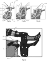
- THE figures 6a to 6d represent sequential views of the assembly of an intermediate fixing part 12b in a dedicated housing 111 of a collector box 11b.
- the intermediate piece 12b comprises a retaining portion 121 and a finger 122.
- the finger 122 projects laterally from the intermediate piece and is intended to fit into an orifice provided in a fixing element 3b.
- the housing 111 of the collector box 11b is arranged to cooperate with the retaining portion 121 of the intermediate piece 12b in order to fix the intermediate piece 12b to the collector box 11b in an assembled position.
- the retaining portion 121 comprises a first vertical part 123 and a second transverse part 124 placed above the first part 123.
- the first part 123 and the second part 124 form an L.
- the first part 123 is arranged to slide vertically in the housing 111 of the collector box 11b.
- the second part 124 comprises a distal end 125 equipped with a lug 126.
- the collector box 11b comprises, on the periphery of the housing 111, an elastically deformable tongue 112 arranged to cooperate with the lug 126 in order to maintain the assembled position of the part intermediate 12b and reservoir 11b.
- the lug 126 has a first rounded face R and a second flat face P.
- the first face R and the second face P have a common edge and are arranged so that when the first part 123 of the intermediate piece 12b slides in the housing 111 of the collector box 11b, the tongue 112 deforms elastically to slide along the first rounded face R then passes the edge to finish abutting against the second face P.
- the retaining portion 121 and the collector box 11b each have an orifice 127 and 113 respectively.
- the orifice 127 of the retaining portion 121 is intended to be opposite the orifice 113 of the collector box 11b in the assembled position so to allow the fixing of the intermediate piece 12b to the tank 11b via a rod, such as a screw or a stud, inserted into the orifices 127 and 113.
- the retaining portion 121 of the intermediate piece 12b further comprises an upper wing 128 intended to rest on an upper edge 114 of the collector box 11b.
- a downward movement is blocked by the stop of the wing 128 on the upper rim 114; upward movement is blocked by the stop of the tongue 112 against the lug 126 and transverse or longitudinal movement is blocked by the complementary shape of the first part 123 of the intermediate piece 12b and of the housing 111 forming a vertical slide.
- the assembled position of the intermediate part 12b and the tank 11b is reinforced by the installation of a rod, screw or stud, in the orifices 127 and 113.
- the collector box On the periphery of the housing 111, the collector box includes a stiffening rib to compensate for the fragility introduced by the material recess made to obtain the housing 111.
Landscapes
- Engineering & Computer Science (AREA)
- Mechanical Engineering (AREA)
- Physics & Mathematics (AREA)
- Thermal Sciences (AREA)
- General Engineering & Computer Science (AREA)
- Chemical & Material Sciences (AREA)
- Combustion & Propulsion (AREA)
- Transportation (AREA)
- Cooling, Air Intake And Gas Exhaust, And Fuel Tank Arrangements In Propulsion Units (AREA)
Description
- L'invention concerne un module de refroidissement et un procédé de montage d'un tel module de refroidissement.
- Un module de refroidissement d'un moteur de véhicule automobile comporte classiquement un radiateur, deux boîtes collectrices fixés latéralement de part et d'autre du radiateur et pour chaque réservoir d'eau, un élément de fixation de la boîte collectrice au véhicule. Les boîtes collectrices comportent des doigts de fixation venus de matière avec le réservoir et destinés à coopérer avec les éléments de fixation pour fixer chaque boîte collectrice à l'élément de fixation correspondant. Un tel module de refroidissement est montré dans le
US 2002/056541 . - Ainsi, pour chaque nouvelle architecture de véhicule, une adaptation de la boîte collectrice et en particulier du doigt de la boîte collectrice est nécessaire pour permettre l'intégration du module de refroidissement dans la nouvelle architecture. Cette adaptation nécessaire empêche une standardisation des modules de refroidissement et en particulier des ensembles comportant le faisceau radiateur et les boîtes collectrices.
- En outre, la complexification de l'architecture des véhicules dans la région du module de refroidissement a rendu le montage plus complexe et plus long et donc plus coûteux.
- Par ailleurs, le fait que le doigt de fixation soit venu de matière avec la boîte collectrice nécessite de changer tout le radiateur en cas de casse du doigt, par exemple lors d'un choc frontal du véhicule. Cette obligation de changer tout le radiateur rend la maintenance coûteuse.
- L'invention propose une solution visant à pallier les inconvénients précités. Un objectif de l'invention est de permettre une réduction de coûts, tant au niveau du coût du module de refroidissement qu'au niveau du coût de montage et du coût de maintenance.
- L'invention concerne un module de refroidissement d'un moteur de véhicule, le module de refroidissement comportant un radiateur, au moins une boîte collectrice fixée au faisceau du radiateur, un élément de fixation de la boîte collectrice au véhicule, le module de refroidissement comportant en outre une pièce intermédiaire de fixation de la boîte collectrice à l'élément de fixation, la pièce intermédiaire comportant une portion de retenue ; la boîte collectrice comportant un logement agencé pour coopérer avec la portion de retenue de la pièce intermédiaire afin de fixer la pièce intermédiaire à la boîte collectrice dans une position assemblée ; la pièce intermédiaire comporte un doigt agencé pour coopérer avec l'élément de fixation afin de fixer la pièce intermédiaire à l'élément de fixation ; le doigt est en saillie latérale de la pièce intermédiaire. La présence d'une pièce intermédiaire permettant de monter la boîte collectrice sur l'élément de fixation permet de standardiser les radiateurs tout en laissant une grande liberté quant à l'architecture du véhicule et notamment quant à l'architecture de la face avant technique. En outre, dans le cadre des normes de sécurité visant à protéger les piétons en cas d'impact avec un véhicule, la pièce intermédiaire est dimensionnée pour céder en cas de choc avant le reste du module de refroidissement. Ainsi, lors des réparations consécutives à un choc, il suffira de changer la pièce intermédiaire plutôt que tout le radiateur ou plutôt qu'un autre élément du module de refroidissement plus coûteux. En outre, ce mode de fixation permet un montage simple et compact.
- Selon une réalisation particulière de l'invention, la portion de retenue comporte une première partie et une deuxième partie, la première partie et la deuxième partie formant un L. Une telle géométrie de la portion de retenue permet un positionnement intuitif de la portion de retenue dans le logement du réservoir, il s'agit également d'une géométrie compacte et robuste.
- Selon une réalisation particulière de l'invention, la première partie est agencée pour coulisser dans le logement du réservoir d'eau. Le coulissement de la première partie dans le logement permet une mise en place simple et rapide de la portion de retenue dans le logement.
- Selon une réalisation particulière de l'invention, la deuxième partie comporte une extrémité distale équipée d'un ergot et en ce que la boîte collectrice comporte, en périphérie du logement, une languette déformable élastiquement agencée pour coopérer avec l'ergot afin de maintenir la position assemblée de la pièce intermédiaire et du réservoir. La coopération de l'ergot et de la languette permet de fixer de manière simple et rapide la portion de retenue dans le logement.
- Selon une réalisation particulière de l'invention, l'ergot comporte une première face arrondie et une deuxième face plane, la première face et la deuxième face comportant une arête commune et étant agencées de sorte que lors du coulissement de la première partie de la pièce intermédiaire dans le logement du réservoir d'eau, la languette se déforme élastiquement pour glisser le long de la première face arrondie puis passe l'arête pour finir en butée contre la deuxième face. L'ergot et la languette forment ainsi un système de clip ergonomique.
- Selon une réalisation particulière de l'invention, la portion de retenue et la boîte collectrice comportent chacun un orifice, l'orifice de la portion de retenue étant destiné à être en regard de l'orifice de la boîte collectrice en position assemblée de sorte à permettre la fixation de la pièce intermédiaire à la boîte collectrice par l'intermédiaire d'une tige, comme une vis ou un goujon, introduite dans les orifices. La tige introduite dans les orifices de la boîte collectrice et de la pièce intermédiaire permet de renforcer la fixation de la pièce intermédiaire au réservoir.
- Selon une réalisation particulière de l'invention, le module de refroidissement comporte deux boîtes collectrices fixées latéralement de part et d'autre du faisceau du radiateur, un élément de fixation par boîte collectrice, une pièce intermédiaire par réservoir d'eau. La présence de deux boîtes collectrices réparties latéralement de part et d'autre du radiateur correspond à une architecture classique de véhicule. La répartition latérale des ensembles de fixation comportant un élément de fixation et une pièce intermédiaire permet d'espacer les points d'ancrage du module de refroidissement sur le véhicule pour obtenir une fixation plus robuste.
- Selon une réalisation particulière de l'invention, le module de refroidissement comporte en outre une patte de fixation par boîte collectrice ; pour chaque boîte collectrice, la pièce intermédiaire étant destinée à être fixée à une première extrémité supérieure de la boîte collectrice et la patte étant placée à une deuxième extrémité inférieure opposée à la première extrémité. La répartition verticale des pièces intermédiaires et des pattes permet d'espacer les points d'ancrage du module de refroidissement sur le véhicule pour obtenir une fixation plus robuste.
- L'invention concerne également un procédé de montage d'un module de refroidissement selon l'invention sur un véhicule caractérisé en ce qu'il comporte les étapes suivantes :
- assemblage du module de refroidissement à une traverse inférieure par l'intermédiaire des pattes de fixation des boîtes collectrices pour former un premier sous-ensemble ;
- positionnement du premier sous-ensemble à une face avant technique selon un mouvement de direction verticale ;
- fixation de la traverse inférieure à la face avant technique ;
- fixation d'une pièce intermédiaire dans le logement dédié de chaque boîte collectrice;
- assemblage d'un élément de fixation sur chaque pièce intermédiaire ;
- positionnement des éléments de fixation contre la face avant technique, ce qui permet un déplacement de la partie supérieure du module de refroidissement selon un mouvement de direction longitudinale ; et
- fixation des éléments de fixation à la face avant technique.
- Un tel procédé est ergonomique, ce qui permet de limiter les coûts liés au montage du module de refroidissement. En particulier, le positionnement selon une direction longitudinale, et non selon d'autres axes, du deuxième sous-ensemble sur l'avant du véhicule permet de réduire le temps de montage. En outre, le fait que la pièce intermédiaire puisse être assemblée alors que la face avant technique est en place avec le module de refroidissement déjà partiellement monté permet de remplacer facilement la pièce intermédiaire, par exemple en cas de casse de la pièce intermédiaire suite à un choc. La maintenance est donc également simplifiée.
- Selon une réalisation particulière de l'invention, l'étape de fixation d'une pièce intermédiaire dans le logement dédié de chaque boîte collectrice comporte les sous-étapes suivantes :
- coulissement de la première partie de la portion de retenue dans le logement ;
- mise en butée de la languette sur l'ergot ; et
- mise en place de la tige dans les orifices en renforcement de la position assemblée de la pièce intermédiaire et du réservoir d'eau.
- La fixation d'une pièce intermédiaire est simple, rapide et donc peu coûteuse tout en étant robuste.
- D'autres caractéristiques et avantages innovants ressortiront de la description ci-après, fournie à titre indicatif et nullement limitatif, en référence aux dessins annexés, dans lesquels :
- La
figure 1 représente une vue schématique et de face d'un module de refroidissement monté sur une face avant technique d'un véhicule selon un mode de réalisation de l'invention ; - La
figure 2 représente une vue schématique et de face d'un module de refroidissement selon un mode de réalisation de l'invention; - La
figure 3 représente une vue schématique en perspective d'un module de refroidissement équipé de deux éléments de fixation selon un mode de réalisation de l'invention ; - La
figure 4 est une vue détaillée en perspective d'un élément de fixation fixé à une boîte collectrice de module de refroidissement et monté sur une face avant technique de véhicule selon un mode de réalisation de l'invention ; - La
figure 5 est une vue détaillée d'une patte de fixation d'une boîte collectrice de module de refroidissement montée sur une traverse inférieure selon un mode de réalisation de l'invention ; et - Les
figures 6a à 6d représentent des vues détaillées en perspective et séquentielles du montage d'une pièce intermédiaire de fixation dans un logement dédié d'une boîte collectrice d'un module de refroidissement selon un procédé de l'invention. - Les
figures 1 à 6d représentent des éléments d'un module de refroidissement d'un moteur de véhicule automobile selon l'invention. Les figures sont orientées suivant un axe longitudinal X pointant vers l'avant, l'axe longitudinal étant parallèle à la direction principale d'élongation du véhicule et l'avant étant défini comme la direction d'avancement du véhicule en marche avant et sans rotation du volant, un axe transversal Y pointant vers la gauche du véhicule et un axe vertical Z pointant vers le haut du véhicule. - La
figure 1 représente un module de refroidissement 1 monté sur une face avant technique 2 de véhicule. La face avant technique 2 est un élément d'architecture du véhicule situé à l'avant du compartiment moteur du véhicule et derrière la calandre. La face avant technique 2 comprend classiquement une traverse inférieure 21 supportant partiellement le module de refroidissement 1, deux montants latéraux 22a et 22b de part et d'autre de la face avant technique 2 et une traverse supérieure 23 apte à supporter les charnières ou la serrure du capot, la traverse comprenant à chaque extrémité un emplacement 230a et 230b de bloc optique du véhicule. En plus d'être supporté par la traverse inférieure 21, le module de refroidissement 1 est fixé en partie supérieure à la face avant technique 2 au niveau de la traverse supérieure 23 par l'intermédiaire de deux éléments de fixation 3a et 3b de part et d'autre du module de refroidissement 2. - La
figure 2 représente un module de refroidissement 1 avant assemblage. Le module de refroidissement 1 comporte un radiateur 10, deux boîtes collectrices 11a et 11b fixés de part et d'autre du radiateur 10 sur les tranches latérales du radiateur 10. Chaque boîte collectrice 11a et 11b est équipé d'une pièce intermédiaire 12a et 12b de fixation de la boîte collectrice à l'un des éléments de fixation 3a ou 3b. Chaque pièce intermédiaire est montée sur une extrémité supérieure de la boîte collectrice correspondant. Chaque pièce intermédiaire 12a ou 12b comporte un doigt en saillie latérale destiné à s'emboîter dans un orifice ménagé dans chaque élément de fixation 3a ou 3b. En outre, chaque boîte collectrice 11a et 11b est équipé d'une patte 13a et 13b de fixation de la boîte collectrice à la traverse inférieure 21. Chaque patte est placée sur une extrémité inférieure de la boîte collectrice correspondante. Chaque patte 13a ou 13b comporte un doigt en saillie inférieure destiné à s'emboîter respectivement dans un premier orifice et un deuxième orifice ménagés dans la traverse inférieure 21. - La
figure 3 représente un module de refroidissement 1 équipé de deux éléments de fixation 3a et 3b emboîtés respectivement sur le doigt des pièces intermédiaires 12a et 12b. Selon une réalisation particulière, un joint par exemple caoutchouc est placé dans l'orifice des éléments de fixation 3a et 3b destiné à recevoir une pièce intermédiaire 12a ou 12b. - La
figure 4 représente un élément de fixation 3a fixé à une boîte collectrice 11a par la pièce intermédiaire 12a. L'élément de fixation 3a est également monté sur une face avant technique 2 de véhicule et plus précisément sur la traverse supérieure 23 de la face avant technique 2. L'élément de fixation 3a est par exemple vissé ou boulonné sur la traverse supérieure 23. - La
figure 5 représente une patte 13a de fixation d'une boîte collectrice 11a montée sur une traverse inférieure 21. Plus précisément, le doigt de la patte 13a est emboîté dans un orifice de la traverse inférieure 21. - Les
figures 6a à 6d représentent des vues séquentielles du montage d'une pièce intermédiaire 12b de fixation dans un logement 111 dédié d'une boîte collectrice 11b. La pièce intermédiaire 12b comporte une portion de retenue 121 et un doigt 122. Le doigt 122 est en saillie latérale de la pièce intermédiaire et est destiné à s'emboîter dans un orifice ménagé dans un élément de fixation 3b. Le logement 111 de la boîte collectrice 11b est agencé pour coopérer avec la portion de retenue 121 de la pièce intermédiaire 12b afin de fixer la pièce intermédiaire 12b à la boîte collectrice 11b dans une position assemblée. - La portion de retenue 121 comporte une première partie 123 verticale et une deuxième partie 124 transversale placée au-dessus de la première partie 123. La première partie 123 et la deuxième partie 124 forment un L. La première partie 123 est agencée pour coulisser verticalement dans le logement 111 de la boîte collectrice 11b. La deuxième partie 124 comporte une extrémité distale 125 équipée d'un ergot 126. La boîte collectrice 11b comporte, en périphérie du logement 111, une languette 112 déformable élastiquement agencée pour coopérer avec l'ergot 126 afin de maintenir la position assemblée de la pièce intermédiaire 12b et du réservoir 11b.
- L'ergot 126 comporte une première face R arrondie et une deuxième face P plane. La première face R et la deuxième face P comportent une arête commune et sont agencées de sorte que lors du coulissement de la première partie 123 de la pièce intermédiaire 12b dans le logement 111 de la boîte collectrice 11b, la languette 112 se déforme élastiquement pour glisser le long de la première face R arrondie puis passe l'arête pour finir en butée contre la deuxième face P.
- La portion de retenue 121 et la boîte collectrice 11b comportent chacun un orifice respectivement 127 et 113. L'orifice 127 de la portion de retenue 121 est destiné à être en regard de l'orifice 113 de la boîte collectrice 11b en position assemblée de sorte à permettre la fixation de la pièce intermédiaire 12b au réservoir 11b par l'intermédiaire d'une tige, comme une vis ou un goujon, introduite dans les orifices 127 et 113.
- La portion de retenue 121 de la pièce intermédiaire 12b comporte en outre une aile 128 supérieure destinée à reposer sur un rebord supérieur 114 de la boîte collectrice 11b. Ainsi, en position assemblée de la pièce intermédiaire 12b et du réservoir 11b, un mouvement vers le bas est bloqué par la butée de l'aile 128 sur le rebord supérieur 114 ; un mouvement vers le haut est bloqué par la butée de la languette 112 contre l'ergot 126 et un mouvement transversal ou longitudinal est bloqué par la forme complémentaire de la première partie 123 de la pièce intermédiaire 12b et du logement 111 formant glissière verticalement. En outre, la position assemblée de la pièce intermédiaire 12b et du réservoir 11b est renforcée par la mise en place d'une tige, vis ou goujon, dans les orifices 127 et 113.
- En périphérie du logement 111, la boîte collectrice comporte une nervure de rigidification pour compenser la fragilité introduite par l'évidement de matière réalisé pour obtenir le logement 111.
- Un procédé de montage d'un module de refroidissement 1 sur un véhicule selon l'invention comporte les étapes suivantes :
- assemblage du module de refroidissement 1 à une traverse inférieure 21 par l'intermédiaire des pattes 13a et 13b de fixation des boîtes collectrices 11a et 11b pour former un premier sous-ensemble ;
- positionnement du premier sous-ensemble à une face avant technique 2 selon un mouvement de direction verticale Z ;
- fixation de la traverse inférieure 21 à la face avant technique 2 ;
- fixation d'une pièce intermédiaire 12a et 12b dans le logement 111 dédié de chaque boîte collectrice 11a et 11b ;
- assemblage d'un élément de fixation 3a et 3b sur chaque pièce intermédiaire respectivement 12a et 12b ;
- positionnement des éléments de fixation 3a et 3b contre la face avant technique 2, ce qui permet un déplacement de la partie supérieure du module de refroidissement 1 selon un mouvement de direction longitudinale X ; et
- fixation des éléments de fixation 3a et 3b à la face avant technique 2.
- L'étape de fixation d'une pièce intermédiaire 12a ou 12b dans le logement 111 dédié de chaque boîte collectrice 11a ou 11b comporte les sous-étapes suivantes :
- coulissement de la première partie 123 de la portion de retenue 121 dans le logement 111 (représentée aux
figures 6a et 6b ) ; - mise en butée de la languette 112 sur l'ergot 126 (représentée à la
figure 6c ) ; et - mise en place de la tige, par exemple une vis à l'aide d'une visseuse 4, dans les orifices 127 et 113 en renforcement de la position assemblée de la pièce intermédiaire 12a ou 12b et de la boîte collectrice 11a ou 11b (représentée à la
figure 6d ) . - L'invention est décrite dans ce qui précède à titre d'exemple.
Claims (10)
- Module de refroidissement (1) d'un moteur de véhicule, le module de refroidissement (1) comportant :- un radiateur (10),- au moins une boîte collectrice (11a, 11b) fixé au radiateur (10),- un élément de fixation (3a, 3b) de la boîte collectrice (11a, 11b) au véhicule,le module de refroidissement (1) étant caractérisé en ce qu'il comporte en outre :- une pièce intermédiaire (12a, 12b) de fixation du de la boîte collectrice (11a, 11b) à l'élément de fixation (3a, 3b), la pièce intermédiaire (12a, 12b) comportant une portion de retenue (121),- la boîte collectrice (11a, 11b) comportant un logement (111) agencé pour coopérer avec la portion de retenue (121) de la pièce intermédiaire (12a, 12b) afin de fixer la pièce intermédiaire (12a, 12b) à la boîte collectrice (11a, 11b) dans une position assemblée- et en ce que la pièce intermédiaire (12a, 12b) comporte un doigt (122) agencé pour coopérer avec l'élément de fixation (3a, 3b) afin de fixer la pièce intermédiaire (12a, 12b) à l'élément de fixation (3a, 3b) et que le doigt (122) est en saillie latérale de la pièce intermédiaire.
- Module de refroidissement (1) selon la revendication 1 caractérisé en ce que la portion de retenue (121) comporte une première partie (123) et une deuxième partie (124), la première partie (123) et la deuxième partie (124) formant un L.
- Module de refroidissement (1) selon la revendication 2 caractérisé en ce que la première partie (123) est agencée pour coulisser dans le logement (111) de la boîte collectrice (11a, 11b).
- Module de refroidissement (1) selon la revendication 3 caractérisé en ce que la deuxième partie (124) comporte une extrémité distale (125) équipée d'un ergot (126) et en ce que la boîte collectrice (11a, 11b) comporte, en périphérie du logement (111), une languette (112) déformable élastiquement agencée pour coopérer avec l'ergot (126) afin de maintenir la position assemblée de la pièce intermédiaire (12a, 12b) et du réservoir (11a, 11b) .
- Module de refroidissement (1) selon la revendication 4 caractérisé en ce que l'ergot (126) comporte une première face (R) arrondie et une deuxième face (P) plane, la première face (R) et la deuxième face (P) comportant une arête commune et étant agencées de sorte que lors du coulissement de la première partie (123) de la pièce intermédiaire (12a, 12b) dans le logement (111) de la boîte collectrice (11a, 11b), la languette (112) se déforme élastiquement pour glisser le long de la première face (R) arrondie puis passe l'arête pour finir en butée contre la deuxième face (P).
- Module de refroidissement (1) selon l'une quelconque des revendications précédentes caractérisé en ce que la portion de retenue (121) et la boîte collectrice (11a, 11b) comportent chacun un orifice, l'orifice (127) de la portion de retenue étant destiné à être en regard de l'orifice (113) de la boîte collectrice (11a, 11b) en position assemblée de sorte à permettre la fixation de la pièce intermédiaire (12a, 12b) à la boîte collectrice(11a, 11b) par l'intermédiaire d'une tige, comme une vis ou un goujon, introduite dans les orifices.
- Module de refroidissement (1) selon l'une quelconque des revendications précédentes caractérisé en ce qu'il comporte :- deux boîtes collectrices (11a, 11b) fixés de part et d'autre du radiateur (10),- un élément de fixation (3a, 3b) par boîte collectrice (11a, 11b),- une pièce intermédiaire (12a, 12b) par boîte collectrice (11a, 11b).
- Module de refroidissement (1) selon la revendication 7 caractérisé en ce qu'il comporte en outre une patte (13a, 13b) de fixation par boîte collectrice (11a, 11b) ; pour chaque réservoir (11a, 11b), la pièce intermédiaire (12a, 12b) étant destinée à être fixée à une première extrémité de la boîte collectrice (11a, 11b) et la patte (13a, 13b) étant placée à une deuxième extrémité opposée à la première extrémité.
- Procédé de montage d'un module de refroidissement (1) selon la revendication 8 sur un véhicule caractérisé en ce qu'il comporte les étapes suivantes :- assemblage du module de refroidissement (1) à une traverse inférieure (21) par l'intermédiaire des pattes (13a, 13b) de fixation des boîtes collectrices (11a, 11b) pour former un premier sous-ensemble ;- positionnement du premier sous-ensemble à une face avant technique (2) selon un mouvement de direction verticale ;- fixation de la traverse inférieure (21) à la face avant technique (2) ;- fixation d'une pièce intermédiaire (12a, 12b) dans le logement (111) dédié de chaque boîte collectrice (11a, 11b) ;- assemblage d'un élément de fixation (3a, 3b) sur chaque pièce intermédiaire (12a, 12b) ;- positionnement des éléments de fixation (3a ; 3b) contre la face avant technique (2), ce qui permet un déplacement de la partie supérieure du module de refroidissement 1 selon un mouvement de direction longitudinale ; et- fixation des éléments de fixation (3a, 3b) à la face avant technique (2).
- Procédé de montage d'un module de refroidissement (1) selon la revendication 9 lorsqu'elle est elle-même dépendante des revendications 4 ou 5 et 6 caractérisé en ce que l'étape de fixation d'une pièce intermédiaire (12a, 12b) dans le logement (111) dédié de chaque boîte collectrice (11a, 11b) comporte les sous-étapes suivantes :- coulissement de la première partie (123) de la portion de retenue (121) dans le logement (111) ;- mise en butée de la languette (112) sur l'ergot (126) ; et- mise en place de la tige dans les orifices (127, 113) en renforcement de la position assemblée de la pièce intermédiaire (12a, 12b) et de la boîte collectrice (11a, 11b).
Applications Claiming Priority (2)
| Application Number | Priority Date | Filing Date | Title |
|---|---|---|---|
| FR1761482A FR3074221B1 (fr) | 2017-11-30 | 2017-11-30 | Module de refroidissement et procede de montage d'un tel module de refroidissement |
| PCT/EP2018/083167 WO2019106155A1 (fr) | 2017-11-30 | 2018-11-30 | Module de refroidissement et procede de montage d'un tel module de refroidissement |
Publications (2)
| Publication Number | Publication Date |
|---|---|
| EP3717292A1 EP3717292A1 (fr) | 2020-10-07 |
| EP3717292B1 true EP3717292B1 (fr) | 2024-06-26 |
Family
ID=61003232
Family Applications (1)
| Application Number | Title | Priority Date | Filing Date |
|---|---|---|---|
| EP18807660.8A Active EP3717292B1 (fr) | 2017-11-30 | 2018-11-30 | Module de refroidissement et procede de montage d'un tel module de refroidissement |
Country Status (5)
| Country | Link |
|---|---|
| EP (1) | EP3717292B1 (fr) |
| KR (1) | KR102605579B1 (fr) |
| CN (1) | CN111386206B (fr) |
| FR (1) | FR3074221B1 (fr) |
| WO (1) | WO2019106155A1 (fr) |
Family Cites Families (8)
| Publication number | Priority date | Publication date | Assignee | Title |
|---|---|---|---|---|
| JPH10205328A (ja) * | 1997-01-22 | 1998-08-04 | Togo Seisakusho Corp | ラジエータの取付け構造 |
| JP2002081884A (ja) * | 2000-09-07 | 2002-03-22 | Denso Corp | 熱交換器の取付構造 |
| IT1321055B1 (it) * | 2000-11-10 | 2003-12-30 | Magneti Marelli Climat Srl | Radiatore per veicoli con perno di fissaggio sostituibile. |
| DE102004058724B4 (de) * | 2003-12-09 | 2018-11-15 | Denso Corporation | Wärmetauscher und Kühlmodul mit diesem |
| FR2936190B1 (fr) * | 2008-09-23 | 2010-12-17 | Renault Sas | Agencement pour la fixation d'un premier dispositif de refroidissement sur un second dispositif de refroidissement d'un moteur a combustion interne |
| FR2955804B1 (fr) * | 2010-02-04 | 2012-03-30 | Peugeot Citroen Automobiles Sa | Systeme de fixation d'un module fonctionnel sur une structure de vehicule. |
| FR2979424B1 (fr) * | 2011-08-22 | 2013-10-25 | Renault Sa | Module de refroidissement d'un vehicule automobile |
| EP2966393B1 (fr) * | 2014-07-07 | 2020-10-21 | Valeo Autosystemy SP. Z.O.O. | Support intégré pour échangeur de chaleur de véhicules automobiles |
-
2017
- 2017-11-30 FR FR1761482A patent/FR3074221B1/fr active Active
-
2018
- 2018-11-30 WO PCT/EP2018/083167 patent/WO2019106155A1/fr not_active Ceased
- 2018-11-30 CN CN201880076353.6A patent/CN111386206B/zh active Active
- 2018-11-30 EP EP18807660.8A patent/EP3717292B1/fr active Active
- 2018-11-30 KR KR1020207018797A patent/KR102605579B1/ko active Active
Also Published As
| Publication number | Publication date |
|---|---|
| CN111386206B (zh) | 2023-10-10 |
| KR20200088896A (ko) | 2020-07-23 |
| KR102605579B1 (ko) | 2023-11-24 |
| FR3074221B1 (fr) | 2020-02-28 |
| EP3717292A1 (fr) | 2020-10-07 |
| CN111386206A (zh) | 2020-07-07 |
| WO2019106155A1 (fr) | 2019-06-06 |
| FR3074221A1 (fr) | 2019-05-31 |
Similar Documents
| Publication | Publication Date | Title |
|---|---|---|
| EP3765337B1 (fr) | Dispositif de support pour element de detection d'un vehicule automobile et son procede de montage | |
| EP2914476B1 (fr) | Dispositif de fixation entre deux pièces structurelles à élément de positionnement flottant | |
| EP3717292B1 (fr) | Module de refroidissement et procede de montage d'un tel module de refroidissement | |
| EP2062804B1 (fr) | Dispositif et procédé de fixation d'un ensemble d'aile sur une paroi de caisse d'un véhicule automobile | |
| EP3317163B1 (fr) | Ensemble comprenant une cloison et un deflecteur | |
| EP2164719B1 (fr) | Module structurel d'emmarchement | |
| EP3833594B1 (fr) | Assemblage simplifie d'un panneau de protection sous-moteur sur vehicule automobile et methode d'assemblage | |
| EP1101691B1 (fr) | Fixation quart avant sur traverse | |
| EP3114012B1 (fr) | Assemblage d'un cockpit et d'une structure de vehicule automobile et procede de montage correspondant | |
| EP3007941B1 (fr) | Dispositif de support pour essuie-vitre | |
| FR3139785A1 (fr) | Support multifonction pour traverse de baie de véhicule automobile | |
| EP3191350B1 (fr) | Module d'essuie glace | |
| EP3271238B1 (fr) | Structure de planche de bord d'un habitacle de vehicule automobile | |
| EP3551504B1 (fr) | Ensemble pour compartiment moteur de vehicule automobile comprenant une unite de controle electronique | |
| EP2080693B1 (fr) | Dispositif de renforcement de cote de caisse d'un vehicule automobile | |
| FR3142234A1 (fr) | Bloc optique d’un projecteur de véhicule automobile | |
| EP4541659A1 (fr) | Pièce de fixation d'un projecteur de véhicule automobile adaptée pour supporter une butée d'un capot du véhicule et dispositif de butée de capot associé | |
| EP2872380B1 (fr) | Dispositif d'indexage d'un equipement de vehicule automobile et procede de fixation d'un equipement. | |
| EP3254903B1 (fr) | Piece de fixation d'elements d'habillage sur un element de structure lateral de vehicule automobile | |
| FR3141382A1 (fr) | Ensemble de façade avant de véhicule automobile à trappe d’anneau de remorquage | |
| FR3139070A1 (fr) | Elément de peau de pare-chocs monobloc de véhicule automobile | |
| EP2028083A1 (fr) | Plancher de vehicule automobile | |
| FR3070147A1 (fr) | Dispositif de fixation d’un equipement sur un chassis de vehicule automobile ayant une cinematique de choc en rotation | |
| FR3057822A1 (fr) | Dispositif de fixation pour un module d'affichage tete haute de vehicule | |
| FR2986760A1 (fr) | Bouclier de vehicule automobile integrant un absorbeur de choc bas et vehicule correspondant |
Legal Events
| Date | Code | Title | Description |
|---|---|---|---|
| STAA | Information on the status of an ep patent application or granted ep patent |
Free format text: STATUS: UNKNOWN |
|
| STAA | Information on the status of an ep patent application or granted ep patent |
Free format text: STATUS: THE INTERNATIONAL PUBLICATION HAS BEEN MADE |
|
| PUAI | Public reference made under article 153(3) epc to a published international application that has entered the european phase |
Free format text: ORIGINAL CODE: 0009012 |
|
| STAA | Information on the status of an ep patent application or granted ep patent |
Free format text: STATUS: REQUEST FOR EXAMINATION WAS MADE |
|
| 17P | Request for examination filed |
Effective date: 20200410 |
|
| AK | Designated contracting states |
Kind code of ref document: A1 Designated state(s): AL AT BE BG CH CY CZ DE DK EE ES FI FR GB GR HR HU IE IS IT LI LT LU LV MC MK MT NL NO PL PT RO RS SE SI SK SM TR |
|
| AX | Request for extension of the european patent |
Extension state: BA ME |
|
| DAV | Request for validation of the european patent (deleted) | ||
| DAX | Request for extension of the european patent (deleted) | ||
| RAP3 | Party data changed (applicant data changed or rights of an application transferred) |
Owner name: RENAULT S.A.S |
|
| RAP3 | Party data changed (applicant data changed or rights of an application transferred) |
Owner name: RENAULT S.A.S |
|
| P01 | Opt-out of the competence of the unified patent court (upc) registered |
Effective date: 20230608 |
|
| GRAP | Despatch of communication of intention to grant a patent |
Free format text: ORIGINAL CODE: EPIDOSNIGR1 |
|
| STAA | Information on the status of an ep patent application or granted ep patent |
Free format text: STATUS: GRANT OF PATENT IS INTENDED |
|
| INTG | Intention to grant announced |
Effective date: 20240123 |
|
| GRAS | Grant fee paid |
Free format text: ORIGINAL CODE: EPIDOSNIGR3 |
|
| GRAA | (expected) grant |
Free format text: ORIGINAL CODE: 0009210 |
|
| STAA | Information on the status of an ep patent application or granted ep patent |
Free format text: STATUS: THE PATENT HAS BEEN GRANTED |
|
| AK | Designated contracting states |
Kind code of ref document: B1 Designated state(s): AL AT BE BG CH CY CZ DE DK EE ES FI FR GB GR HR HU IE IS IT LI LT LU LV MC MK MT NL NO PL PT RO RS SE SI SK SM TR |
|
| REG | Reference to a national code |
Ref country code: GB Ref legal event code: FG4D Free format text: NOT ENGLISH |
|
| REG | Reference to a national code |
Ref country code: CH Ref legal event code: EP |
|
| REG | Reference to a national code |
Ref country code: DE Ref legal event code: R096 Ref document number: 602018071062 Country of ref document: DE |
|
| PG25 | Lapsed in a contracting state [announced via postgrant information from national office to epo] |
Ref country code: BG Free format text: LAPSE BECAUSE OF FAILURE TO SUBMIT A TRANSLATION OF THE DESCRIPTION OR TO PAY THE FEE WITHIN THE PRESCRIBED TIME-LIMIT Effective date: 20240626 |
|
| PG25 | Lapsed in a contracting state [announced via postgrant information from national office to epo] |
Ref country code: FI Free format text: LAPSE BECAUSE OF FAILURE TO SUBMIT A TRANSLATION OF THE DESCRIPTION OR TO PAY THE FEE WITHIN THE PRESCRIBED TIME-LIMIT Effective date: 20240626 Ref country code: HR Free format text: LAPSE BECAUSE OF FAILURE TO SUBMIT A TRANSLATION OF THE DESCRIPTION OR TO PAY THE FEE WITHIN THE PRESCRIBED TIME-LIMIT Effective date: 20240626 |
|
| REG | Reference to a national code |
Ref country code: LT Ref legal event code: MG9D |
|
| PG25 | Lapsed in a contracting state [announced via postgrant information from national office to epo] |
Ref country code: GR Free format text: LAPSE BECAUSE OF FAILURE TO SUBMIT A TRANSLATION OF THE DESCRIPTION OR TO PAY THE FEE WITHIN THE PRESCRIBED TIME-LIMIT Effective date: 20240927 |
|
| PG25 | Lapsed in a contracting state [announced via postgrant information from national office to epo] |
Ref country code: LV Free format text: LAPSE BECAUSE OF FAILURE TO SUBMIT A TRANSLATION OF THE DESCRIPTION OR TO PAY THE FEE WITHIN THE PRESCRIBED TIME-LIMIT Effective date: 20240626 |
|
| REG | Reference to a national code |
Ref country code: NL Ref legal event code: MP Effective date: 20240626 |
|
| PG25 | Lapsed in a contracting state [announced via postgrant information from national office to epo] |
Ref country code: NO Free format text: LAPSE BECAUSE OF FAILURE TO SUBMIT A TRANSLATION OF THE DESCRIPTION OR TO PAY THE FEE WITHIN THE PRESCRIBED TIME-LIMIT Effective date: 20240926 Ref country code: LV Free format text: LAPSE BECAUSE OF FAILURE TO SUBMIT A TRANSLATION OF THE DESCRIPTION OR TO PAY THE FEE WITHIN THE PRESCRIBED TIME-LIMIT Effective date: 20240626 Ref country code: HR Free format text: LAPSE BECAUSE OF FAILURE TO SUBMIT A TRANSLATION OF THE DESCRIPTION OR TO PAY THE FEE WITHIN THE PRESCRIBED TIME-LIMIT Effective date: 20240626 Ref country code: GR Free format text: LAPSE BECAUSE OF FAILURE TO SUBMIT A TRANSLATION OF THE DESCRIPTION OR TO PAY THE FEE WITHIN THE PRESCRIBED TIME-LIMIT Effective date: 20240927 Ref country code: FI Free format text: LAPSE BECAUSE OF FAILURE TO SUBMIT A TRANSLATION OF THE DESCRIPTION OR TO PAY THE FEE WITHIN THE PRESCRIBED TIME-LIMIT Effective date: 20240626 Ref country code: BG Free format text: LAPSE BECAUSE OF FAILURE TO SUBMIT A TRANSLATION OF THE DESCRIPTION OR TO PAY THE FEE WITHIN THE PRESCRIBED TIME-LIMIT Effective date: 20240626 Ref country code: RS Free format text: LAPSE BECAUSE OF FAILURE TO SUBMIT A TRANSLATION OF THE DESCRIPTION OR TO PAY THE FEE WITHIN THE PRESCRIBED TIME-LIMIT Effective date: 20240926 |
|
| PG25 | Lapsed in a contracting state [announced via postgrant information from national office to epo] |
Ref country code: NL Free format text: LAPSE BECAUSE OF FAILURE TO SUBMIT A TRANSLATION OF THE DESCRIPTION OR TO PAY THE FEE WITHIN THE PRESCRIBED TIME-LIMIT Effective date: 20240626 |
|
| REG | Reference to a national code |
Ref country code: AT Ref legal event code: MK05 Ref document number: 1697435 Country of ref document: AT Kind code of ref document: T Effective date: 20240626 |
|
| PG25 | Lapsed in a contracting state [announced via postgrant information from national office to epo] |
Ref country code: NL Free format text: LAPSE BECAUSE OF FAILURE TO SUBMIT A TRANSLATION OF THE DESCRIPTION OR TO PAY THE FEE WITHIN THE PRESCRIBED TIME-LIMIT Effective date: 20240626 |
|
| PG25 | Lapsed in a contracting state [announced via postgrant information from national office to epo] |
Ref country code: PT Free format text: LAPSE BECAUSE OF FAILURE TO SUBMIT A TRANSLATION OF THE DESCRIPTION OR TO PAY THE FEE WITHIN THE PRESCRIBED TIME-LIMIT Effective date: 20241028 |
|
| PG25 | Lapsed in a contracting state [announced via postgrant information from national office to epo] |
Ref country code: PT Free format text: LAPSE BECAUSE OF FAILURE TO SUBMIT A TRANSLATION OF THE DESCRIPTION OR TO PAY THE FEE WITHIN THE PRESCRIBED TIME-LIMIT Effective date: 20241028 |
|
| PG25 | Lapsed in a contracting state [announced via postgrant information from national office to epo] |
Ref country code: PL Free format text: LAPSE BECAUSE OF FAILURE TO SUBMIT A TRANSLATION OF THE DESCRIPTION OR TO PAY THE FEE WITHIN THE PRESCRIBED TIME-LIMIT Effective date: 20240626 |
|
| PG25 | Lapsed in a contracting state [announced via postgrant information from national office to epo] |
Ref country code: EE Free format text: LAPSE BECAUSE OF FAILURE TO SUBMIT A TRANSLATION OF THE DESCRIPTION OR TO PAY THE FEE WITHIN THE PRESCRIBED TIME-LIMIT Effective date: 20240626 |
|
| PG25 | Lapsed in a contracting state [announced via postgrant information from national office to epo] |
Ref country code: IS Free format text: LAPSE BECAUSE OF FAILURE TO SUBMIT A TRANSLATION OF THE DESCRIPTION OR TO PAY THE FEE WITHIN THE PRESCRIBED TIME-LIMIT Effective date: 20241026 Ref country code: AT Free format text: LAPSE BECAUSE OF FAILURE TO SUBMIT A TRANSLATION OF THE DESCRIPTION OR TO PAY THE FEE WITHIN THE PRESCRIBED TIME-LIMIT Effective date: 20240626 |
|
| PG25 | Lapsed in a contracting state [announced via postgrant information from national office to epo] |
Ref country code: CZ Free format text: LAPSE BECAUSE OF FAILURE TO SUBMIT A TRANSLATION OF THE DESCRIPTION OR TO PAY THE FEE WITHIN THE PRESCRIBED TIME-LIMIT Effective date: 20240626 |
|
| PG25 | Lapsed in a contracting state [announced via postgrant information from national office to epo] |
Ref country code: RO Free format text: LAPSE BECAUSE OF FAILURE TO SUBMIT A TRANSLATION OF THE DESCRIPTION OR TO PAY THE FEE WITHIN THE PRESCRIBED TIME-LIMIT Effective date: 20240626 Ref country code: SK Free format text: LAPSE BECAUSE OF FAILURE TO SUBMIT A TRANSLATION OF THE DESCRIPTION OR TO PAY THE FEE WITHIN THE PRESCRIBED TIME-LIMIT Effective date: 20240626 |
|
| PG25 | Lapsed in a contracting state [announced via postgrant information from national office to epo] |
Ref country code: SM Free format text: LAPSE BECAUSE OF FAILURE TO SUBMIT A TRANSLATION OF THE DESCRIPTION OR TO PAY THE FEE WITHIN THE PRESCRIBED TIME-LIMIT Effective date: 20240626 Ref country code: ES Free format text: LAPSE BECAUSE OF FAILURE TO SUBMIT A TRANSLATION OF THE DESCRIPTION OR TO PAY THE FEE WITHIN THE PRESCRIBED TIME-LIMIT Effective date: 20240626 |
|
| PG25 | Lapsed in a contracting state [announced via postgrant information from national office to epo] |
Ref country code: SM Free format text: LAPSE BECAUSE OF FAILURE TO SUBMIT A TRANSLATION OF THE DESCRIPTION OR TO PAY THE FEE WITHIN THE PRESCRIBED TIME-LIMIT Effective date: 20240626 Ref country code: SK Free format text: LAPSE BECAUSE OF FAILURE TO SUBMIT A TRANSLATION OF THE DESCRIPTION OR TO PAY THE FEE WITHIN THE PRESCRIBED TIME-LIMIT Effective date: 20240626 Ref country code: RO Free format text: LAPSE BECAUSE OF FAILURE TO SUBMIT A TRANSLATION OF THE DESCRIPTION OR TO PAY THE FEE WITHIN THE PRESCRIBED TIME-LIMIT Effective date: 20240626 Ref country code: PL Free format text: LAPSE BECAUSE OF FAILURE TO SUBMIT A TRANSLATION OF THE DESCRIPTION OR TO PAY THE FEE WITHIN THE PRESCRIBED TIME-LIMIT Effective date: 20240626 Ref country code: IS Free format text: LAPSE BECAUSE OF FAILURE TO SUBMIT A TRANSLATION OF THE DESCRIPTION OR TO PAY THE FEE WITHIN THE PRESCRIBED TIME-LIMIT Effective date: 20241026 Ref country code: ES Free format text: LAPSE BECAUSE OF FAILURE TO SUBMIT A TRANSLATION OF THE DESCRIPTION OR TO PAY THE FEE WITHIN THE PRESCRIBED TIME-LIMIT Effective date: 20240626 Ref country code: EE Free format text: LAPSE BECAUSE OF FAILURE TO SUBMIT A TRANSLATION OF THE DESCRIPTION OR TO PAY THE FEE WITHIN THE PRESCRIBED TIME-LIMIT Effective date: 20240626 Ref country code: CZ Free format text: LAPSE BECAUSE OF FAILURE TO SUBMIT A TRANSLATION OF THE DESCRIPTION OR TO PAY THE FEE WITHIN THE PRESCRIBED TIME-LIMIT Effective date: 20240626 Ref country code: AT Free format text: LAPSE BECAUSE OF FAILURE TO SUBMIT A TRANSLATION OF THE DESCRIPTION OR TO PAY THE FEE WITHIN THE PRESCRIBED TIME-LIMIT Effective date: 20240626 |
|
| PG25 | Lapsed in a contracting state [announced via postgrant information from national office to epo] |
Ref country code: IT Free format text: LAPSE BECAUSE OF FAILURE TO SUBMIT A TRANSLATION OF THE DESCRIPTION OR TO PAY THE FEE WITHIN THE PRESCRIBED TIME-LIMIT Effective date: 20240626 |
|
| REG | Reference to a national code |
Ref country code: DE Ref legal event code: R097 Ref document number: 602018071062 Country of ref document: DE |
|
| PG25 | Lapsed in a contracting state [announced via postgrant information from national office to epo] |
Ref country code: DK Free format text: LAPSE BECAUSE OF FAILURE TO SUBMIT A TRANSLATION OF THE DESCRIPTION OR TO PAY THE FEE WITHIN THE PRESCRIBED TIME-LIMIT Effective date: 20240626 |
|
| PLBE | No opposition filed within time limit |
Free format text: ORIGINAL CODE: 0009261 |
|
| STAA | Information on the status of an ep patent application or granted ep patent |
Free format text: STATUS: NO OPPOSITION FILED WITHIN TIME LIMIT |
|
| 26N | No opposition filed |
Effective date: 20250327 |
|
| REG | Reference to a national code |
Ref country code: CH Ref legal event code: PL |
|
| PG25 | Lapsed in a contracting state [announced via postgrant information from national office to epo] |
Ref country code: MC Free format text: LAPSE BECAUSE OF FAILURE TO SUBMIT A TRANSLATION OF THE DESCRIPTION OR TO PAY THE FEE WITHIN THE PRESCRIBED TIME-LIMIT Effective date: 20240626 |
|
| PG25 | Lapsed in a contracting state [announced via postgrant information from national office to epo] |
Ref country code: LU Free format text: LAPSE BECAUSE OF NON-PAYMENT OF DUE FEES Effective date: 20241130 |
|
| REG | Reference to a national code |
Ref country code: CH Ref legal event code: PL |
|
| GBPC | Gb: european patent ceased through non-payment of renewal fee |
Effective date: 20241130 |
|
| PG25 | Lapsed in a contracting state [announced via postgrant information from national office to epo] |
Ref country code: CH Free format text: LAPSE BECAUSE OF NON-PAYMENT OF DUE FEES Effective date: 20241130 |
|
| REG | Reference to a national code |
Ref country code: BE Ref legal event code: MM Effective date: 20241130 |
|
| PG25 | Lapsed in a contracting state [announced via postgrant information from national office to epo] |
Ref country code: SE Free format text: LAPSE BECAUSE OF FAILURE TO SUBMIT A TRANSLATION OF THE DESCRIPTION OR TO PAY THE FEE WITHIN THE PRESCRIBED TIME-LIMIT Effective date: 20240626 |
|
| PG25 | Lapsed in a contracting state [announced via postgrant information from national office to epo] |
Ref country code: GB Free format text: LAPSE BECAUSE OF NON-PAYMENT OF DUE FEES Effective date: 20241130 Ref country code: BE Free format text: LAPSE BECAUSE OF NON-PAYMENT OF DUE FEES Effective date: 20241130 |
|
| PG25 | Lapsed in a contracting state [announced via postgrant information from national office to epo] |
Ref country code: IE Free format text: LAPSE BECAUSE OF NON-PAYMENT OF DUE FEES Effective date: 20241130 |
|
| PGFP | Annual fee paid to national office [announced via postgrant information from national office to epo] |
Ref country code: DE Payment date: 20251119 Year of fee payment: 8 |
|
| PGFP | Annual fee paid to national office [announced via postgrant information from national office to epo] |
Ref country code: FR Payment date: 20251126 Year of fee payment: 8 |
|
| PG25 | Lapsed in a contracting state [announced via postgrant information from national office to epo] |
Ref country code: CY Free format text: LAPSE BECAUSE OF FAILURE TO SUBMIT A TRANSLATION OF THE DESCRIPTION OR TO PAY THE FEE WITHIN THE PRESCRIBED TIME-LIMIT; INVALID AB INITIO Effective date: 20181130 |