EP3716643A1 - Hybridlautsprecher - Google Patents
Hybridlautsprecher Download PDFInfo
- Publication number
- EP3716643A1 EP3716643A1 EP18879371.5A EP18879371A EP3716643A1 EP 3716643 A1 EP3716643 A1 EP 3716643A1 EP 18879371 A EP18879371 A EP 18879371A EP 3716643 A1 EP3716643 A1 EP 3716643A1
- Authority
- EP
- European Patent Office
- Prior art keywords
- frequency sound
- low
- frequency
- woofer
- tweeter
- Prior art date
- Legal status (The legal status is an assumption and is not a legal conclusion. Google has not performed a legal analysis and makes no representation as to the accuracy of the status listed.)
- Withdrawn
Links
Images


Classifications
-
- H—ELECTRICITY
- H04—ELECTRIC COMMUNICATION TECHNIQUE
- H04R—LOUDSPEAKERS, MICROPHONES, GRAMOPHONE PICK-UPS OR LIKE ACOUSTIC ELECTROMECHANICAL TRANSDUCERS; ELECTRIC HEARING AIDS; PUBLIC ADDRESS SYSTEMS
- H04R1/00—Details of transducers, loudspeakers or microphones
- H04R1/20—Arrangements for obtaining desired frequency or directional characteristics
- H04R1/22—Arrangements for obtaining desired frequency or directional characteristics for obtaining desired frequency characteristic only
- H04R1/26—Spatial arrangements of separate transducers responsive to two or more frequency ranges
-
- H—ELECTRICITY
- H04—ELECTRIC COMMUNICATION TECHNIQUE
- H04R—LOUDSPEAKERS, MICROPHONES, GRAMOPHONE PICK-UPS OR LIKE ACOUSTIC ELECTROMECHANICAL TRANSDUCERS; ELECTRIC HEARING AIDS; PUBLIC ADDRESS SYSTEMS
- H04R9/00—Transducers of moving-coil, moving-strip, or moving-wire type
- H04R9/02—Details
- H04R9/025—Magnetic circuit
-
- H—ELECTRICITY
- H04—ELECTRIC COMMUNICATION TECHNIQUE
- H04R—LOUDSPEAKERS, MICROPHONES, GRAMOPHONE PICK-UPS OR LIKE ACOUSTIC ELECTROMECHANICAL TRANSDUCERS; ELECTRIC HEARING AIDS; PUBLIC ADDRESS SYSTEMS
- H04R9/00—Transducers of moving-coil, moving-strip, or moving-wire type
- H04R9/06—Loudspeakers
-
- H—ELECTRICITY
- H04—ELECTRIC COMMUNICATION TECHNIQUE
- H04R—LOUDSPEAKERS, MICROPHONES, GRAMOPHONE PICK-UPS OR LIKE ACOUSTIC ELECTROMECHANICAL TRANSDUCERS; ELECTRIC HEARING AIDS; PUBLIC ADDRESS SYSTEMS
- H04R1/00—Details of transducers, loudspeakers or microphones
- H04R1/20—Arrangements for obtaining desired frequency or directional characteristics
- H04R1/22—Arrangements for obtaining desired frequency or directional characteristics for obtaining desired frequency characteristic only
- H04R1/24—Structural combinations of separate transducers or of two parts of the same transducer and responsive respectively to two or more frequency ranges
-
- H—ELECTRICITY
- H04—ELECTRIC COMMUNICATION TECHNIQUE
- H04R—LOUDSPEAKERS, MICROPHONES, GRAMOPHONE PICK-UPS OR LIKE ACOUSTIC ELECTROMECHANICAL TRANSDUCERS; ELECTRIC HEARING AIDS; PUBLIC ADDRESS SYSTEMS
- H04R13/00—Transducers having an acoustic diaphragm of magnetisable material directly co-acting with electromagnet
-
- H—ELECTRICITY
- H04—ELECTRIC COMMUNICATION TECHNIQUE
- H04R—LOUDSPEAKERS, MICROPHONES, GRAMOPHONE PICK-UPS OR LIKE ACOUSTIC ELECTROMECHANICAL TRANSDUCERS; ELECTRIC HEARING AIDS; PUBLIC ADDRESS SYSTEMS
- H04R31/00—Apparatus or processes specially adapted for the manufacture of transducers or diaphragms therefor
- H04R31/006—Interconnection of transducer parts
-
- H—ELECTRICITY
- H04—ELECTRIC COMMUNICATION TECHNIQUE
- H04R—LOUDSPEAKERS, MICROPHONES, GRAMOPHONE PICK-UPS OR LIKE ACOUSTIC ELECTROMECHANICAL TRANSDUCERS; ELECTRIC HEARING AIDS; PUBLIC ADDRESS SYSTEMS
- H04R9/00—Transducers of moving-coil, moving-strip, or moving-wire type
- H04R9/02—Details
Definitions
- the present invention relates to a speaker, and more particularly, to a hybrid speaker which includes a tweeter of a high-frequency range and a woofer of a low-frequency range on the same axis and improves sound quality by separately discharging a high-frequency sound generated by the tweeter of the high-frequency range and a low-frequency sound generated by the woofer of the low-frequency range.
- speakers are classified, according to principles and methods of converting electrical signals into sound waves, into a dynamic speaker, an electromagnetic speaker, a static speaker, a dielectric speaker, a magnetostrictive speaker, and the like.
- Dynamic speakers which are most generally used, use a principle that when a voice signal current is applied to a (voice) coil in a magnetic field of a magnet, a mechanical force acts on the coil to initiate a movement according to intensity of the current.
- speakers are often classified into a radiative speaker having a diaphragm directly disposed in the air and a horn speaker having a diaphragm disposed in a horn.
- a magnetic speaker operated by vibrations of an armature of a magnetic body is referred to as a balanced armature (BA) speaker.
- BA balanced armature
- armatures disposed above and below coils inside a metal case keep a balance among the coils and float without being attached to any side due to magnets present with the coils.
- the coils are magnetized such that the armatures having metallic materials vibrate according to magnetic forces and vibrations are transferred to a diaphragm (vibrating plate) through a thin rod.
- the diaphragm vibrates and generates a sound.
- a material of a diaphragm a 100% metal plate, or a variety of materials such as metal coated with plastic, a plastic plate, and the like are used. Since such BA speakers are drivers invented for hearing aids, they have a small size and a light weight.
- a plate type speaker has a fast reaction property of very faithfully responding to a micro signal of a supplied electrical signal since an additional secondary vibration transfer element is unnecessary and a vibrating plate is capable of reproducing a sound wave by directly vibrating air.
- Korean Patent Registration No. 1596894 discloses a balanced plate type electromagnetic speaker.
- the electromagnetic speaker includes an upper coil, a lower coil disposed below the upper coil, a diaphragm disposed between the upper coil and the lower coil, one or more magnets disposed outside the upper coil and the lower coil, an upper damping member supporting a top surface of the diaphragm and a lower damping member supporting a bottom surface of the diaphragm.
- the diaphragm when a current flow is zero, the diaphragm is neutralized and is located in a center due to a balance between upper and lower magnetic fields of the upper and lower magnets and a restoring force of the diaphragm.
- an internal magnetic field direction of the upper coil and an internal magnetic field direction of the lower coil are internally symmetrical to each other such that the diaphragm is N-polarized and moves in an upward direction.
- the internal magnetic field direction of the upper coil and the internal magnetic field direction of the lower coil are externally symmetrical to each other such that the diaphragm is S-polarized and moves in a downward direction.
- an amplitude space is necessary as well as efficiency decreasing due to increasing magnetic resistance and a thickness of the speaker increasing.
- conventional electromagnetic speakers have good resolution but generally show limited performance in extension of a low-frequency sound and a super high-frequency sound. Accordingly, speakers having new features for reproducing both a high-frequency sound and a low-frequency sound in higher quality are necessary.
- the present invention is directed to providing a hybrid speaker capable of reducing a loss of sound by separately discharging a high-frequency sound generated by a tweeter of a high-frequency range and a low-frequency sound generated by a woofer of a low-frequency range.
- One aspect of the present invention provides a hybrid speaker in which a low-frequency sound discharge path formed in a low-frequency space of a woofer portion and a high-frequency sound discharge path formed in a high-frequency sound space of a tweeter portion do not overlap each other and are separated from each other.
- the hybrid speaker includes the woofer portion implemented as a dynamic speaker in which when a current flows through a low-frequency voice coil disposed on a magnetic circuit, a low-frequency sound diaphragm vibrates and generates a low-frequency sound, the tweeter portion implemented as a plate type electromagnetic speaker in which a magnet and a coil are arranged on each of an upper side and a lower side on the basis of a high-frequency sound diaphragm in a balance state and each coil becomes an electromagnet and generates a high-frequency sound by magnetizing the high-frequency sound diaphragm, a substrate disposed between the woofer portion and the tweeter portion to divide the low-frequency sound space of the woofer portion and the high-frequency sound space of the tweeter portion and to supply an electrical signal to the coil of each of the woofer portion and the tweeter portion, a lower frame configured to accommodate components on the same axis, and an upper frame coupled to the lower frame to form a single-body speaker housing in which a low-frequency sound outlet
- the lower frame may include a frame body configured to accommodate a yoke and a magnet of the woofer portion and a woofer cover configured to accommodate the low-frequency sound diaphragm and to support the upper frame.
- the upper frame may include a low-frequency sound case in which the low-frequency sound outlet configured to discharge the low-frequency sound generated in the low space of the woofer portion from a peripheral part of the speaker housing is formed, and a high-frequency sound case in which the high-frequency sound outlet configured to discharge the high-frequency sound generated in the high-frequency sound space of the tweeter portion from a center of the speaker housing so as to tune the high-frequency sound by adjusting an area or disposition of the low-frequency sound outlet is formed.
- a speaker has a hybrid structure in which a tweeter in a high-frequency range is implemented as a plate type electromagnetic speaker having a favorable high-frequency sound property and a woofer in a low-frequency range is implemented as a dynamic speaker such that the electromagnetic speaker and the dynamic speaker are coupled with each other so as to form an overall thin shape and improve sound properties throughout a low-frequency range and a high-frequency range.
- a speaker according to the present invention provides effects of maximizing performance since a tweeter in a high-frequency range and a woofer in a low-frequency range are implemented as a single body on the same axis while sound outlets thereof are separately provided and effects of simplifying a manufacturing process and increasing productivity since a frame of the tweeter in the high-frequency range is replaceable with a cover of the woofer in the low-frequency range.
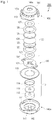
- FIG. 1 is an exploded perspective view of a hybrid speaker according to the present invention
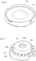
- FIG. 2 is a coupled perspective view of the hybrid speaker according to the present invention
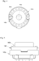
- FIG. 3 is a side cross-sectional view of the hybrid speaker according to the present invention
- FIG. 4 is a plan view of the hybrid speaker according to the present invention
- FIG. 5 is a front view of the hybrid speaker according to the present invention.
- a woofer portion 110 having excellent low-frequency sound properties, a tweeter portion 120 having excellent high-frequency sound properties, and a substrate 130 configured to supply an electrical signal to a coil while distinguishing a low-frequency sound space of the woofer portion 110 and a high-frequency sound space of the tweeter portion 120 are integrally coupled on the same axis between a lower frame 140a and an upper frame 140b.
- the woofer portion 110 is a dynamic type speaker including a yoke 111, a low-frequency sound magnet 112, a plate 113, a low-frequency voice coil 114, and a low-frequency sound diaphragm 115
- the tweeter portion 120 is a plate type electromagnetic speaker including a first high-frequency sound coil 121, a first high-frequency sound magnet 122, a first gap guide 123, a high-frequency sound diaphragm 124, a second gap guide 125, a second high-frequency sound magnet 126, and a second high-frequency sound coil 127.
- the lower frame 140a includes a frame body 142 and a woofer cover 141.
- a cylindrical groove is formed in a central part of the frame body 142 to accommodate the cylindrical yoke 111, and an axial column 142a protrudes from a center to couple the respective elements on the same axis.
- the magnet 112 and the plate 113 are sequentially stacked inside the yoke 111 and form a cavity between the yoke 111 and the plate 113, and the voice coil 114 is attached to a bottom surface of the low-frequency sound diaphragm 115 and disposed in the cavity.
- the low-frequency sound diaphragm 115 includes a dome portion in a center and an edge portion on a periphery.
- the woofer portion 110 operates as a dynamic speaker in which a magnetic field between the magnet 112 and the yoke 111 interacts with the voice coil 114 and the low-frequency sound diaphragm 115 is vibrated when a current flows through the voice coil 114.
- the high-frequency sound diaphragm 124 in the center floats in a space due to gap guides 123 and 125 which function as both upper and lower dampers, the first coil 121 and the first magnet 122 are horizontally arranged below the high-frequency sound diaphragm 124, and the second magnet 126 and the second coil 127 are horizontally arranged above the high-frequency sound diaphragm 124.
- all the magnets 122 and 126 or the coils 121 and 127 have annular shapes.
- the magnets 122 and 126 are disposed outside the coils 121 and 127.
- the gap guides 123 and 125 are inserted between the magnets 122 and 126 and the diaphragm 124 and form a space for vibration of the high-frequency sound diaphragm 124.
- the high-frequency sound diaphragm 124 is neutralized and located in a center due to upper and lower magnetic field balance between the first and second magnets 122 and 126 and a restoration force of the diaphragm.
- a magnetization direction may vary according to a magnetic pole array direction of the first magnet 122 and the second magnet 126.
- the substrate 130 has a structure in which an electrode pad 132 is formed on a printed circuit board (PCB) 131 and is disposed between the woofer portion 110 and the tweeter portion 120 to divide a low-frequency sound space and a high-frequency sound space and supplies an audio signal current to each of the voice coil 114 of the woofer portion 110 and the first coil 121 and the second coil 127 of the tweeter portion 120.
- PCB printed circuit board
- the upper frame 140b includes a low-frequency sound case 143 including a low-frequency sound outlet 143a for discharging a low-frequency sound generated in the low-frequency sound space of the woofer portion 110 and a high-frequency sound case 144 including a high-frequency outlet 144a for discharging a high-frequency sound generated in a high-frequency sound space of the tweeter portion 120.
- the low-frequency sound case 143 is formed on a circumferential part, and the high-frequency sound case 144 protrudes from a central part.
- one high-frequency sound outlet 144a is formed in a central part of the high-frequency sound case 144 and a plurality of such low-frequency sound outlets 143a are formed on a circumferential part of the low-frequency sound case 143.
- the low-frequency sound outlet 143a is separated from the high-frequency sound outlets 144a, there is an advantage of being capable of tuning a sound in a high-frequency range by adjusting an area, disposition, and the like of the low-frequency sound outlet.
- FIG. 6 is a perspective view illustrating a subassembly of the woofer portion of the hybrid speaker according to the present invention
- FIG. 7 is a perspective view illustrating a subassembly of the tweeter portion of the hybrid speaker according to the present invention
- FIG. 8 is a view illustrating acoustic properties of the hybrid speaker according to the present invention.
- an audio current flows through the voice coil 114 of the woofer portion.
- a current flows through the voice coil 114 disposed in a cavity of a magnetic circuit including the magnet 112, the plate 113, and the yoke 111 of the woofer portion 110, a magnetic field is formed along a direction of the current and interacts with the magnetic circuit such that the low-frequency sound diaphragm 115 vertically vibrates and a low-frequency sound of the woofer portion generated by the vibrations of the low-frequency sound diaphragm 115 is discharged outward through the low-frequency sound outlet 143a of the upper frame.
- the diaphragm 124 vertically vibrates and generates a high-frequency sound of the tweeter portion and the high-frequency sound of the tweeter portion is discharged outward through the high outlet 144a.
- the hybrid speaker 100 has a structure in which a woofer subassembly shown in FIG. 6 and the tweeter subassembly shown in FIG. 7 are vertically arranged on the same axis, in which a low-frequency sound generated by the woofer portion 110 is discharged through the low-frequency sound outlet 143a and a high-frequency sound generated by the tweeter portion 120 is discharged through the high-frequency sound outlet 144a such that a loss in the high-frequency sound may be reduced to improve sound quality.
- the acoustic feature of the present invention has been significantly improved as described above in comparison to a conventional structure having one outlet as shown in FIG. 8 .
- G2 is a line illustrating a conventional acoustic property and G1 is a line illustrating an acoustic property according to the present invention.
- G1 is a line illustrating an acoustic property according to the present invention.
Landscapes
- Physics & Mathematics (AREA)
- Engineering & Computer Science (AREA)
- Acoustics & Sound (AREA)
- Signal Processing (AREA)
- Health & Medical Sciences (AREA)
- Otolaryngology (AREA)
- Audible-Bandwidth Dynamoelectric Transducers Other Than Pickups (AREA)
- Obtaining Desirable Characteristics In Audible-Bandwidth Transducers (AREA)
- Electrostatic, Electromagnetic, Magneto- Strictive, And Variable-Resistance Transducers (AREA)
Applications Claiming Priority (2)
| Application Number | Priority Date | Filing Date | Title |
|---|---|---|---|
| KR1020170155045A KR101907513B1 (ko) | 2017-11-20 | 2017-11-20 | 하이브리드 스피커 |
| PCT/KR2018/008031 WO2019098487A1 (ko) | 2017-11-20 | 2018-07-16 | 하이브리드 스피커 |
Publications (2)
| Publication Number | Publication Date |
|---|---|
| EP3716643A1 true EP3716643A1 (de) | 2020-09-30 |
| EP3716643A4 EP3716643A4 (de) | 2021-08-11 |
Family
ID=63876299
Family Applications (1)
| Application Number | Title | Priority Date | Filing Date |
|---|---|---|---|
| EP18879371.5A Withdrawn EP3716643A4 (de) | 2017-11-20 | 2018-07-16 | Hybridlautsprecher |
Country Status (6)
| Country | Link |
|---|---|
| US (1) | US11128948B2 (de) |
| EP (1) | EP3716643A4 (de) |
| JP (1) | JP6926341B2 (de) |
| KR (1) | KR101907513B1 (de) |
| CN (1) | CN111164989B (de) |
| WO (1) | WO2019098487A1 (de) |
Families Citing this family (22)
| Publication number | Priority date | Publication date | Assignee | Title |
|---|---|---|---|---|
| KR102070202B1 (ko) | 2018-11-13 | 2020-01-29 | 주식회사 비에스이 | 실장이 용이한 하이브리드 스피커 |
| KR102277889B1 (ko) * | 2019-11-08 | 2021-07-15 | 주식회사 비에스이 | 초박형 2웨이 스피커 |
| KR102287436B1 (ko) * | 2020-04-17 | 2021-08-09 | 주식회사 이어브릿지 | 초박형 하이브리드 스피커 |
| CN111836159B (zh) * | 2020-09-21 | 2021-01-22 | 歌尔股份有限公司 | 发声模组 |
| US11528563B2 (en) * | 2020-09-22 | 2022-12-13 | Em-Tech Co., Ltd. | Hybrid receiver having fixing bracket for drivers |
| KR102453587B1 (ko) * | 2020-09-22 | 2022-10-14 | 주식회사 이엠텍 | 마이크 일체형 리시버 모듈 및 이를 구비하는 이어폰 |
| KR20220089739A (ko) * | 2020-12-21 | 2022-06-29 | 현대자동차주식회사 | 전기자동차의 가상 효과 구현 장치 |
| CN114915882B (zh) * | 2021-02-10 | 2024-08-23 | Oppo广东移动通信有限公司 | 混合扬声器及音频再现装置 |
| EP4290883A1 (de) * | 2021-02-10 | 2023-12-13 | Guangdong Oppo Mobile Telecommunications Corp., Ltd. | Hybridlautsprecher und audiowiedergabevorrichtung |
| CN115226008B (zh) * | 2021-04-15 | 2025-07-01 | Oppo广东移动通信有限公司 | 扬声器及音频再现装置 |
| CN113194390A (zh) * | 2021-04-23 | 2021-07-30 | 歌尔股份有限公司 | 发声装置 |
| CN113781992A (zh) * | 2021-09-17 | 2021-12-10 | 厦门圣德斯贵电子科技有限公司 | 一种微型降噪模块 |
| CN113810832A (zh) * | 2021-09-17 | 2021-12-17 | 厦门圣德斯贵电子科技有限公司 | 微型扬声器 |
| KR102706706B1 (ko) * | 2022-04-21 | 2024-09-19 | 주식회사 이엠텍 | 하이브리드 마이크로스피커 |
| KR102636158B1 (ko) * | 2022-10-05 | 2024-02-14 | 부전전자 주식회사 | MEMS 스피커를 내장한 2way 스피커 |
| KR102676512B1 (ko) * | 2022-10-12 | 2024-06-20 | 주식회사 이엠텍 | 투웨이 스피커용 사운드 필터 |
| US12317051B2 (en) * | 2022-11-25 | 2025-05-27 | Aac Technologies (Nanjing) Co., Ltd. | Multifunctional speaker device |
| US12407977B2 (en) * | 2023-02-27 | 2025-09-02 | Aac Microtech (Changzhou) Co., Ltd. | Speaker device and headphone |
| WO2024207437A1 (zh) * | 2023-04-07 | 2024-10-10 | 瑞声光电科技(常州)有限公司 | 微型扬声器 |
| KR102848476B1 (ko) * | 2024-01-24 | 2025-08-21 | 주식회사 알머스 | 이어폰용 스피커 유닛 |
| CN223053094U (zh) * | 2024-07-25 | 2025-07-01 | 东莞市世威电子科技有限公司 | 一种阵列分频扬声器的耳机 |
| CN119383501A (zh) * | 2024-10-17 | 2025-01-28 | 浙江未来精灵人工智能科技有限公司 | 音箱 |
Family Cites Families (22)
| Publication number | Priority date | Publication date | Assignee | Title |
|---|---|---|---|---|
| US4418248A (en) * | 1981-12-11 | 1983-11-29 | Koss Corporation | Dual element headphone |
| KR100519637B1 (ko) * | 2002-03-30 | 2005-10-06 | 주식회사 삼부커뮤닉스 | 2-웨이 스피커 |
| JP4006636B2 (ja) | 2002-10-24 | 2007-11-14 | 日本電気株式会社 | 複合型スピーカ |
| JP2005277866A (ja) * | 2004-03-25 | 2005-10-06 | Pioneer Electronic Corp | 樹脂フレーム、スピーカーユニット及びスピーカー装置 |
| KR100632480B1 (ko) * | 2004-11-18 | 2006-10-16 | 황경환 | 콘덴서 스피커 |
| US7577269B2 (en) * | 2006-08-28 | 2009-08-18 | Technology Properties Limited | Acoustic transducer |
| CN202121770U (zh) * | 2011-06-24 | 2012-01-18 | 徐曙华 | 功放输出驱动与感应电压驱动复合型全频扬声器 |
| US9036839B2 (en) * | 2013-06-05 | 2015-05-19 | Harman International Industries, Inc. | Multi-way coaxial loudspeaker with magnetic cylinder |
| KR101587477B1 (ko) * | 2013-11-15 | 2016-01-21 | 주식회사 진영지앤티 | 초박형 스피커 |
| KR101501898B1 (ko) * | 2014-01-28 | 2015-03-23 | 주식회사 진영지앤티 | 일체형 2웨이 스피커 및 이를 포함하는 기기 |
| CN203859863U (zh) * | 2014-05-20 | 2014-10-01 | 惠阳东美音响制品有限公司 | 同轴同音源扬声器结构 |
| KR101738902B1 (ko) * | 2014-10-23 | 2017-05-25 | 주식회사 알머스 | 다이나믹 스피커와 압전 소자를 이용한 고음질 스피커 |
| CN204046806U (zh) * | 2014-08-20 | 2014-12-24 | 中山市天键电声有限公司 | 一种采用双动圈单元的喇叭 |
| KR101596894B1 (ko) * | 2014-12-30 | 2016-02-23 | 유옥정 | 밸런스드 플레이트 방식의 전자석 스피커 |
| CN204518027U (zh) * | 2015-04-24 | 2015-07-29 | 捷音特科技股份有限公司 | 反向声波耳机 |
| TWM508868U (zh) * | 2015-04-24 | 2015-09-11 | Jetvox Acoustic Corp | 反向聲波耳機 |
| CN204929219U (zh) * | 2015-06-25 | 2015-12-30 | 东莞正任电子有限公司 | 一种耳机扬声器用新型振膜及具有该新型振膜的耳机扬声器 |
| CN205847589U (zh) * | 2016-07-20 | 2016-12-28 | 广州世韵电子科技有限公司 | 一种薄型喇叭结构 |
| KR101760291B1 (ko) * | 2016-08-23 | 2017-07-24 | 레프릭오디오주식회사 | 다이나믹 스피커를 이용한 일체형 2웨이 스피커 |
| KR101909234B1 (ko) * | 2016-11-21 | 2018-10-17 | 주식회사 이어브릿지 | 하이브리드 스피커 |
| CN107046666A (zh) * | 2017-03-06 | 2017-08-15 | 深圳市冠旭电子股份有限公司 | 一种发声装置及耳机 |
| CN107147978A (zh) * | 2017-05-25 | 2017-09-08 | 东莞合律美电子科技有限公司 | 一种分频喇叭 |
-
2017
- 2017-11-20 KR KR1020170155045A patent/KR101907513B1/ko not_active Expired - Fee Related
-
2018
- 2018-07-16 WO PCT/KR2018/008031 patent/WO2019098487A1/ko not_active Ceased
- 2018-07-16 US US16/652,262 patent/US11128948B2/en not_active Expired - Fee Related
- 2018-07-16 CN CN201880061377.4A patent/CN111164989B/zh not_active Expired - Fee Related
- 2018-07-16 EP EP18879371.5A patent/EP3716643A4/de not_active Withdrawn
- 2018-07-16 JP JP2020538506A patent/JP6926341B2/ja not_active Expired - Fee Related
Also Published As
| Publication number | Publication date |
|---|---|
| US20200245058A1 (en) | 2020-07-30 |
| JP2020534769A (ja) | 2020-11-26 |
| JP6926341B2 (ja) | 2021-08-25 |
| KR101907513B1 (ko) | 2018-10-12 |
| EP3716643A4 (de) | 2021-08-11 |
| WO2019098487A1 (ko) | 2019-05-23 |
| US11128948B2 (en) | 2021-09-21 |
| CN111164989A (zh) | 2020-05-15 |
| CN111164989B (zh) | 2021-08-20 |
Similar Documents
| Publication | Publication Date | Title |
|---|---|---|
| US11128948B2 (en) | Hybrid speaker | |
| KR101057078B1 (ko) | 다기능 마이크로 스피커 | |
| US10820106B2 (en) | Speaker module | |
| CN113055795B (zh) | 发声装置和耳机 | |
| WO2024000686A1 (zh) | 同轴扬声器 | |
| CN112770237B (zh) | 发声单体 | |
| US12407975B2 (en) | Coaxial speaker | |
| WO2022166374A1 (zh) | 发声单体 | |
| WO2022166388A1 (zh) | 发声装置和耳机 | |
| KR20210055960A (ko) | 초박형 2웨이 스피커 | |
| KR102070202B1 (ko) | 실장이 용이한 하이브리드 스피커 | |
| US20120308070A1 (en) | Slim type speaker and magnetic circuit therefor | |
| US11310604B2 (en) | Flat speaker driven by a single permanent magnet and one or more voice coils | |
| KR20100122349A (ko) | 다기능 마이크로 스피커 | |
| US20230111935A1 (en) | Electroacoustic transducer and loudspeaker, microphone and electronic device comprising said electroacoustic transducer | |
| CN118413788A (zh) | 扬声器模组及其组装方法、扬声器、终端设备 | |
| JP2004502365A (ja) | 小型高性能スピーカ | |
| CN219181668U (zh) | 高性能薄型扬声器 | |
| KR102636952B1 (ko) | 전자기방식 고음스피커 | |
| KR102731038B1 (ko) | 점진동 스피커 | |
| KR20180059995A (ko) | 광대역 고해상 전자기 스피커 | |
| KR20060059367A (ko) | 스피커 | |
| KR20230168506A (ko) | 진동 안정성을 향상시킨 스피커 | |
| KR20230076475A (ko) | 자성체 진동판을 이용한 평판형 트위터 스피커 | |
| KR20180003538U (ko) | 수동 복사 스피커 |
Legal Events
| Date | Code | Title | Description |
|---|---|---|---|
| STAA | Information on the status of an ep patent application or granted ep patent |
Free format text: STATUS: THE INTERNATIONAL PUBLICATION HAS BEEN MADE |
|
| PUAI | Public reference made under article 153(3) epc to a published international application that has entered the european phase |
Free format text: ORIGINAL CODE: 0009012 |
|
| STAA | Information on the status of an ep patent application or granted ep patent |
Free format text: STATUS: REQUEST FOR EXAMINATION WAS MADE |
|
| 17P | Request for examination filed |
Effective date: 20200325 |
|
| AK | Designated contracting states |
Kind code of ref document: A1 Designated state(s): AL AT BE BG CH CY CZ DE DK EE ES FI FR GB GR HR HU IE IS IT LI LT LU LV MC MK MT NL NO PL PT RO RS SE SI SK SM TR |
|
| AX | Request for extension of the european patent |
Extension state: BA ME |
|
| DAV | Request for validation of the european patent (deleted) | ||
| DAX | Request for extension of the european patent (deleted) | ||
| A4 | Supplementary search report drawn up and despatched |
Effective date: 20210712 |
|
| RIC1 | Information provided on ipc code assigned before grant |
Ipc: H04R 1/26 20060101AFI20210706BHEP Ipc: H04R 9/06 20060101ALI20210706BHEP |
|
| STAA | Information on the status of an ep patent application or granted ep patent |
Free format text: STATUS: THE APPLICATION IS DEEMED TO BE WITHDRAWN |
|
| 18D | Application deemed to be withdrawn |
Effective date: 20220209 |