EP3716286B1 - Systems for improved sustainment of a high performance frc and high harmonic fast wave electron heating in a high performance frc - Google Patents
Systems for improved sustainment of a high performance frc and high harmonic fast wave electron heating in a high performance frc Download PDFInfo
- Publication number
- EP3716286B1 EP3716286B1 EP20172605.6A EP20172605A EP3716286B1 EP 3716286 B1 EP3716286 B1 EP 3716286B1 EP 20172605 A EP20172605 A EP 20172605A EP 3716286 B1 EP3716286 B1 EP 3716286B1
- Authority
- EP
- European Patent Office
- Prior art keywords
- frc
- plasma
- confinement chamber
- confinement
- divertors
- Prior art date
- Legal status (The legal status is an assumption and is not a legal conclusion. Google has not performed a legal analysis and makes no representation as to the accuracy of the status listed.)
- Active
Links
Images


Classifications
-
- G—PHYSICS
- G21—NUCLEAR PHYSICS; NUCLEAR ENGINEERING
- G21B—FUSION REACTORS
- G21B1/00—Thermonuclear fusion reactors
-
- G—PHYSICS
- G21—NUCLEAR PHYSICS; NUCLEAR ENGINEERING
- G21B—FUSION REACTORS
- G21B1/00—Thermonuclear fusion reactors
- G21B1/05—Thermonuclear fusion reactors with magnetic or electric plasma confinement
-
- G—PHYSICS
- G21—NUCLEAR PHYSICS; NUCLEAR ENGINEERING
- G21B—FUSION REACTORS
- G21B1/00—Thermonuclear fusion reactors
- G21B1/05—Thermonuclear fusion reactors with magnetic or electric plasma confinement
- G21B1/052—Thermonuclear fusion reactors with magnetic or electric plasma confinement reversed field configuration
-
- G—PHYSICS
- G21—NUCLEAR PHYSICS; NUCLEAR ENGINEERING
- G21B—FUSION REACTORS
- G21B1/00—Thermonuclear fusion reactors
- G21B1/11—Details
-
- G—PHYSICS
- G21—NUCLEAR PHYSICS; NUCLEAR ENGINEERING
- G21D—NUCLEAR POWER PLANT
- G21D7/00—Arrangements for direct production of electric energy from fusion or fission reactions
-
- H—ELECTRICITY
- H05—ELECTRIC TECHNIQUES NOT OTHERWISE PROVIDED FOR
- H05H—PLASMA TECHNIQUE; PRODUCTION OF ACCELERATED ELECTRICALLY-CHARGED PARTICLES OR OF NEUTRONS; PRODUCTION OR ACCELERATION OF NEUTRAL MOLECULAR OR ATOMIC BEAMS
- H05H1/00—Generating plasma; Handling plasma
- H05H1/02—Arrangements for confining plasma by electric or magnetic fields; Arrangements for heating plasma
- H05H1/10—Arrangements for confining plasma by electric or magnetic fields; Arrangements for heating plasma using externally-applied magnetic fields only, e.g. Q-machines, Yin-Yang, base-ball
- H05H1/12—Arrangements for confining plasma by electric or magnetic fields; Arrangements for heating plasma using externally-applied magnetic fields only, e.g. Q-machines, Yin-Yang, base-ball wherein the containment vessel forms a closed or nearly closed loop
-
- H—ELECTRICITY
- H05—ELECTRIC TECHNIQUES NOT OTHERWISE PROVIDED FOR
- H05H—PLASMA TECHNIQUE; PRODUCTION OF ACCELERATED ELECTRICALLY-CHARGED PARTICLES OR OF NEUTRONS; PRODUCTION OR ACCELERATION OF NEUTRAL MOLECULAR OR ATOMIC BEAMS
- H05H1/00—Generating plasma; Handling plasma
- H05H1/02—Arrangements for confining plasma by electric or magnetic fields; Arrangements for heating plasma
- H05H1/10—Arrangements for confining plasma by electric or magnetic fields; Arrangements for heating plasma using externally-applied magnetic fields only, e.g. Q-machines, Yin-Yang, base-ball
- H05H1/14—Arrangements for confining plasma by electric or magnetic fields; Arrangements for heating plasma using externally-applied magnetic fields only, e.g. Q-machines, Yin-Yang, base-ball wherein the containment vessel is straight and has magnetic mirrors
-
- H—ELECTRICITY
- H05—ELECTRIC TECHNIQUES NOT OTHERWISE PROVIDED FOR
- H05H—PLASMA TECHNIQUE; PRODUCTION OF ACCELERATED ELECTRICALLY-CHARGED PARTICLES OR OF NEUTRONS; PRODUCTION OR ACCELERATION OF NEUTRAL MOLECULAR OR ATOMIC BEAMS
- H05H1/00—Generating plasma; Handling plasma
- H05H1/02—Arrangements for confining plasma by electric or magnetic fields; Arrangements for heating plasma
- H05H1/16—Arrangements for confining plasma by electric or magnetic fields; Arrangements for heating plasma using externally-applied electric and magnetic fields
-
- Y—GENERAL TAGGING OF NEW TECHNOLOGICAL DEVELOPMENTS; GENERAL TAGGING OF CROSS-SECTIONAL TECHNOLOGIES SPANNING OVER SEVERAL SECTIONS OF THE IPC; TECHNICAL SUBJECTS COVERED BY FORMER USPC CROSS-REFERENCE ART COLLECTIONS [XRACs] AND DIGESTS
- Y02—TECHNOLOGIES OR APPLICATIONS FOR MITIGATION OR ADAPTATION AGAINST CLIMATE CHANGE
- Y02E—REDUCTION OF GREENHOUSE GAS [GHG] EMISSIONS, RELATED TO ENERGY GENERATION, TRANSMISSION OR DISTRIBUTION
- Y02E30/00—Energy generation of nuclear origin
- Y02E30/10—Nuclear fusion reactors
Definitions
- the Field Reversed Configuration belongs to a class of magnetic plasma confinement topologies known as compact toroids (CT).
- CT Compact toroids
- the FRC exhibits predominantly poloidal magnetic fields and possesses zero or small self-generated toroidal fields (see M. Tuszewski, Nucl. Fusion 28, 2033 (1988 )).
- the attractions of such a configuration are its simple geometry for ease of construction and maintenance, a natural unrestricted divertor for facilitating energy extraction and ash removal, and very high ⁇ ( ⁇ is the ratio of the average plasma pressure to the average magnetic field pressure inside the FRC), i.e., high power density.
- ⁇ is the ratio of the average plasma pressure to the average magnetic field pressure inside the FRC
- the high ⁇ nature is advantageous for economic operation and for the use of advanced, aneutronic fuels such as D-He 3 and p-B 11 .
- the traditional method of forming an FRC uses the field-reversed ⁇ -pinch technology, producing hot, high-density plasmas (see A. L. Hoffman and J. T. Slough, Nucl. Fusion 33, 27 (1993 )).
- a variation on this is the translation-trapping method in which the plasma created in a theta-pinch "source” is more-or-less immediately ejected out one end into a confinement chamber. The translating plasmoid is then trapped between two strong mirrors at the ends of the chamber (see, for instance, H. Himura, S. Okada, S. Sugimoto, and S. Goto, Phys. Plasmas 2, 191 (1995 )).
- FRCs have proved to be extremely robust, resilient to dynamic formation, translation, and violent capture events. Moreover, they show a tendency to assume a preferred plasma state (see e.g. H. Y. Guo, A. L. Hoffman, K. E. Miller, and L. C. Steinhauer, Phys. Rev. Lett. 92, 245001 (2004 )).
- FRCs consist of a torus of closed field lines inside a separatrix, and of an annular edge layer on the open field lines just outside the separatrix. The edge layer coalesces into jets beyond the FRC length, providing a natural divertor.
- the FRC topology coincides with that of a Field-Reversed-Mirror plasma.
- the FRC plasma has a ⁇ of about 10.
- the inherent low internal magnetic field provides for a certain indigenous kinetic particle population, i.e. particles with large larmor radii, comparable to the FRC minor radius. It is these strong kinetic effects that appear to at least partially contribute to the gross stability of past and present FRCs, such as those produced in the collision-merging experiment.
- the edge layer particle confinement time ⁇ ⁇ is essentially an axial transit time in past FRC experiments. In steady-state, the balance between radial and axial particle losses yields a separatrix density gradient length ⁇ ⁇ (D ⁇ ⁇ ⁇ ) 1/2 .
- the FRC particle confinement time scales as ( ⁇ ⁇ ⁇ ⁇ ) 1/2 for past FRCs that have substantial density at the separatrix (see e.g. M. TUSZEWSKI, "Field Reversed Configurations," Nucl. Fusion 28, 2033 (1988 )).
- WO2016070126-A1 discloses a high performance FRC system including a central confinement vessel, two diametrically opposed reversed-field-theta-pinch formation sections coupled to the vessel, and two divertor chambers coupled to the formation sections.
- a magnetic system includes quasi-dc coils is axially positioned along the FRC system components, quasi-dc mirror coils between the confinement chamber and the formation sections, and mirror plugs between the formation sections and the divertors.
- the present invention provides a system for generating and maintaining a magnetic field with a field reversed configuration in accordance with claim 1.
- the present embodiments provided herein are directed to systems and methods that facilitate forming and maintaining FRCs with superior stability as well as particle, energy and flux confinement. Some of the present embodiments are directed to systems and methods that facilitate forming and maintaining FRCs with elevated system energies and temperatures and improved sustainment utilizing neutral beam injection and high harmonic fast wave electron heating.
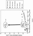
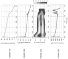
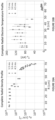
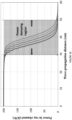
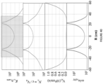
- Figure 1 depicts particle confinement in an FRC system 10 described below (see Figures 2 and 3 ), operating in accordance with a High Performance FRC regime (HPF) for forming and maintaining an FRC versus operating in accordance with a conventional regime CR for forming and maintaining an FRC, and versus particle confinement in accordance with conventional regimes for forming and maintaining an FRC used in other experiments.
- HPF High Performance FRC regime
- the present disclosure will outline and detail the innovative individual components of the FRC system 10 and methods as well as their collective effects.
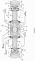
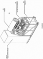
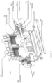
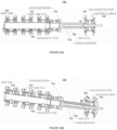
- FIGS 2 and 3 depict a schematic of the present FRC system 10.
- the FRC system 10 includes a central confinement vessel 100 surrounded by two diametrically opposed reversed-field-theta-pinch formation sections 200 and, beyond the formation sections 200, two divertor chambers 300 to control neutral density and impurity contamination.
- the present FRC system 10 was built to accommodate ultrahigh vacuum and operates at typical base pressures of 10 -8 torr. Such vacuum pressures require the use of double-pumped mating flanges between mating components, metal O-rings, high purity interior walls, as well as careful initial surface conditioning of all parts prior to assembly, such as physical and chemical cleaning followed by a 24 hour 250 °C vacuum baking and Hydrogen glow discharge cleaning.
- the reversed-field-theta-pinch formation sections 200 are standard field-reversed-theta-pinches (FRTPs), albeit with an advanced pulsed power formation system discussed in detail below (see Figures 4 through 6 ).
- Each formation section 200 is made of standard opaque industrial grade quartz tubes that feature a 2 millimeter inner lining of ultrapure quartz.
- the confinement chamber 100 is made of stainless steel to allow a multitude of radial and tangential ports; it also serves as a flux conserver on the timescale of the experiments described below and limits fast magnetic transients. Vacuums are created and maintained within the FRC system 10 with a set of dry scroll roughing pumps, turbo molecular pumps and cryo pumps.
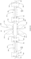
- the magnetic system 400 is illustrated in Figures 2 and 3 .
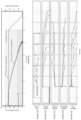
- Figure 2 illustrates an FRC magnetic flux and density contours (as functions of the radial and axial coordinates) pertaining to an FRC 450 producible by the FRC system 10. These contours were obtained by a 2-D resistive Hall-MHD numerical simulation using code developed to simulate systems and methods corresponding to the FRC system 10, and agree well with measured experimental data.
- the FRC 450 consists of a torus of closed field lines at the interior 453 of the FRC 450 inside a separatrix 451, and of an annular edge layer 456 on the open field lines 452 just outside the separatrix 451.
- the edge layer 456 coalesces into jets 454 beyond the FRC length, providing a natural divertor.
- each formation system 210 stores between 350-400 kJ of capacitive energy, which provides up to 35 GW of power to form and accelerate the FRCs. Coordinated operation of these components is achieved via a state-of-the-art trigger and control system 222 and 224 that allows synchronized timing between the formation systems 210 on each formation section 200 and minimizes switching jitter to tens of nanoseconds.
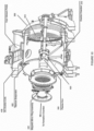
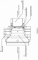
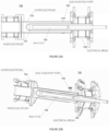
- the systems 610 and 640 are based on positive ion multi-aperture extraction sources and utilize geometric focusing, inertial cooling of the ion extraction grids and differential pumping. Apart from using different plasma sources, the systems 610 and 640 are primarily differentiated by their physical design to meet their respective mounting locations, yielding side and top injection capabilities. Typical components of these neutral beam injectors are specifically illustrated in Figure 7 for the side injector systems 610. As shown in Figure 7 , each individual neutral beam system 610 includes an RF plasma source 612 at an input end (this is substituted with an arc source in systems 640) with a magnetic screen 614 covering the end.
- An ion optical source and acceleration grids 616 is coupled to the plasma source 612 and a gate valve 620 is positioned between the ion optical source and acceleration grids 616 and a neutralizer 622.
- a deflection magnet 624 and an ion dump 628 are located between the neutralizer 622 and an aiming device 630 at the exit end.
- a cooling system comprises two cryo-refrigerators 634, two cryopanels 636 and a LN2 shroud 638. This flexible design allows for operation over a broad range of FRC parameters.
- such angling and positioning of the beam injectors 615 can allow beams of higher energy (which is generally more favorable for depositing more power with less beam divergence) to be injected into lower magnetic fields than would otherwise be necessary to trap such beams. This is due to the fact that it is the azimuthal component of the energy that determines fast ion orbit scale (which becomes progressively smaller as the injection angle relative to the vessel's major axis of symmetry is reduced at constant beam energy). Furthermore, angled injection towards the mid-plane and with axial beam positions close to the mid-plane improves beam-plasma coupling, even as the FRC plasma shrinks or otherwise axially contracts during the injection period.
- the second set of mirror coils 430 which includes three compact quasi-dc mirror coils 432, 434 and 436, is located between the formation sections 200 and the divertors 300 and are driven by a common switching power supply.
- the mirror coils 432, 434 and 436, together with the more compact pulsed mirror plug coils 444 (fed by a capacitive power supply) and the physical constriction 442 form the mirror plugs 440 that provide a narrow low gas conductance path with very high magnetic fields (between 2 to 4 T with rise times of about 10 to 20 ms).
- the most compact pulsed mirror coils 444 are of compact radial dimensions, bore of 20 cm and similar length, compared to the meter-plus-scale bore and pancake design of the confinement coils 412, 414 and 416.
- the purpose of the mirror plugs 440 is multifold: (1) The coils 432, 434, 436 and 444 tightly bundle and guide the magnetic flux surfaces 452 and end-streaming plasma jets 454 into the remote divertor chambers 300. This assures that the exhaust particles reach the divertors 300 appropriately and that there are continuous flux surfaces 455 that trace from the open field line 452 region of the central FRC 450 all the way to the divertors 300.
- the constrictions 442 prevent back-streaming of gas from the formation sections 200 to the divertors 300 thereby reducing the number of neutral particles that has to be introduced into the entire FRC system 10 when commencing the startup of an FRC.
- the strong axial mirrors produced by the coils 432, 434, 436 and 444 reduce axial particle losses and thereby reduce the parallel particle diffusivity on open field lines.
- Electrical biasing of open flux surfaces can provide radial potentials that give rise to azimuthal E ⁇ B motion that provides a control mechanism, analogous to turning a knob, to control rotation of the open field line plasma as well as the actual FRC core 450 via velocity shear.
- the FRC system 10 employs various electrodes strategically placed in various parts of the machine.
- Figure 3 depicts biasing electrodes positioned at preferred locations within the FRC system 10.
- the plasma confinement time in this regime is ⁇ gd ⁇ RL/2V s ⁇ 2 ms, where V s is the ion sound speed.
- the classical ion confinement time for these plasma parameters would be ⁇ c ⁇ 0.5 ⁇ ii (lnR + (lnR) 0.5 ) ⁇ 0.7 ms.
- the anomalous transverse diffusion may, in principle, shorten the plasma confinement time.
- the estimated transverse confinement time for the gun plasma is ⁇ ⁇ > ⁇ gd ⁇ 2 ms.
- the guns would provide significant refueling of the FRC edge layer 456, and an improved overall FRC particle confinement.
- edge layer 456 directly impacts the FRC core 453. Furthermore, since the free energy in the plasma rotation can also be responsible for instabilities, this technique provides a direct means to control the onset and growth of instabilities.
- appropriate edge biasing provides an effective control of open field line transport and rotation as well as FRC core rotation.
- the location and shape of the various provided electrodes 900, 905, 910 and 920 allows for control of different groups of flux surfaces 455 and at different and independent potentials. In this way a wide array of different electric field configurations and strengths can be realized, each with different characteristic impact on plasma performance.
- a key advantage of all these innovative biasing techniques is the fact that core and edge plasma behavior can be affected from well outside the FRC plasma, i.e. there is no need to bring any physical components in touch with the central hot plasma (which would have severe implications for energy, flux and particle losses). This has a major beneficial impact on performance and all potential applications of the HPF concept.
- the correlation between beam pulse length and FRC lifetime is not perfect as beam trapping becomes inefficient below a certain plasma size, i.e., as the FRC 450 shrinks in physical size not all of the injected beams are intercepted and trapped.
- Shrinkage of the FRC is primarily due to the fact that net energy loss ( ⁇ 4 MW about midway through the discharge) from the FRC plasma during the discharge is somewhat larger than the total power fed into the FRC via the neutral beams ( ⁇ 2.5 MW) for the particular experimental setup. Locating the beams at a location closer to the mid-plane of the vessel 100 would tend to reduce these losses and extend FRC lifetime.
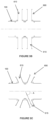
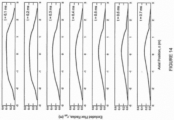
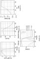
- Figures 17A, 17B, 17C and 17D illustrate the effects of different components to achieve the HPF regime. It shows a family of typical curves depicting the lifetime of the FRC 450 as a function of time. In all cases a constant, modest amount of beam power (about 2.5 MW) is injected for the full duration of each discharge. Each curve is representative of a different combination of components.
- operating the FRC system 10 without any mirror plugs 440, plasma guns 350 or gettering from the gettering systems 800 results in rapid onset of rotational instability and loss of the FRC topology. Adding only the mirror plugs 440 delays the onset of instabilities and increases confinement. Utilizing the combination of mirror plugs 440 and a plasma gun 350 further reduces instabilities and increases FRC lifetime.
- Figure 1 illustrates the change in particle confinement time in the FRC system 10 between the conventionally regime and the HPF regime. As can be seen, it has improved by well over a factor of 5 in the HPF regime.
- Figure 1 details the particle confinement time in the FRC system 10 relative to the particle confinement time in prior conventional FRC experiments.
- the HPF regime of the FRC system 10 has improved confinement by a factor of between 5 and close to 20.
- the nature of the confinement scaling of the FRC system 10 in the HPF regime is dramatically different from all prior measurements.
- the HPF regime is vastly superior and shows that much better confinement is attainable without large machine size or high magnetic fields. More importantly, it is also clear from Figure 1 that the HPF regime results in improved confinement time with reduced plasma size as compared to the CR regime. Similar trends are also visible for flux and energy confinement times, as described below, which have increased by over a factor of 3-8 in the FRC system 10 as well.
- the breakthrough of the HPF regime therefore, enables the use of modest beam power, lower magnetic fields and smaller size to sustain and maintain FRC equilibria in the FRC system 10 and future higher energy machines. Hand-in-hand with these improvements comes lower operating and construction costs as well as reduced engineering complexity.
- the energy, particle and flux confinement times are 0.5 ms, 1 ms and 1 ms, respectively.
- the stored plasma energy is 2 kJ while the losses are about 4 MW, making this target very suitable for neutral beam sustainment.
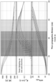
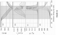
- FIG 19 summarizes all advantages of the HPF regime in the form of a newly established experimental HPF flux confinement scaling.
- the flux confinement (and similarly, particle confinement and energy confinement) scales with roughly the square of the electron Temperature ( T e ) for a given separatrix radius (r s ).
- T e electron Temperature
- r s separatrix radius
- this scaling is a direct consequence of the HPF state and the large orbit (i.e. orbits on the scale of the FRC topology and/or at least the characteristic magnetic field gradient length scale) ion population. Fundamentally, this new scaling substantially favors high operating temperatures and enables relatively modest sized reactors.
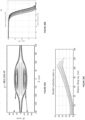
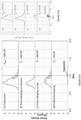
- Figure 20 shows data in plot A from a representative HPF regime discharge in the FRC system 10 as a function of time and in plot B for a projected representative HPF regime discharge in the FRC system 10 as a function of time where the FRC 450 is sustained without decay through the duration of the neutral beam pulse.
- neutral beams with total power in the range of about 2.5-2.9 MW were injected into the FRC 450 for an active beam pulse length of about 6 ms.
- the plasma diamagnetic lifetime depicted in plot A was about 5.2 ms. More recent data shows a plasma diamagnetic lifetime of about 7.2 ms is achievable with an active beam pulse length of about 7 ms.
- the correlation between beam pulse length and FRC lifetime is not perfect as beam trapping becomes inefficient below a certain plasma size, i.e., as the FRC 450 shrinks in physical size not all of the injected beams are intercepted and trapped.
- Shrinkage or decay of the FRC is primarily due to the fact that net energy loss (- 4 MW about midway through the discharge) from the FRC plasma during the discharge is somewhat larger than the total power fed into the FRC via the neutral beams (-2.5 MW) for the particular experimental setup.
- angled beam injection from the neutral beam guns 600 towards the mid-plane improves beam-plasma coupling, even as the FRC plasma shrinks or otherwise axially contracts during the injection period.
- appropriate pellet fueling will maintain the requisite plasma density.
- Plot B is the result of simulations run using an active beam pulse length of about 6 ms and total beam power from the neutral beam guns 600 of slightly more than about 10 MW, where neutral beams shall inject H (or D) neutrals with particle energy of about 15 keV.
- the equivalent current injected by each of the beams is about 110 A.
- the beam injection angle to the device axis was about 20° less than normal with a target radius of 0.19 m. Injection angle can be changed within the range 15° - 25° less than normal.
- the beams are to be injected in the co-current direction azimuthally.
- the net side force as well as net axial force from the neutral beam momentum injection shall be minimized.
- fast (H) neutrals are injected from the neutral beam injectors 600 from the moment the north and south formation FRCs merge in the confinement chamber 100 into one FRC 450.
- the steady state diamagnetic lifetime of the FRC 450 will be the length of the beam pulse.
- the key correlation plot B shows is that when the beams are turned off the plasma or FRC begins to decay at that time, but not before. The decay will be similar to that which is observed in discharges which are not beam-assisted - probably on order of 1 ms beyond the beam turn off time - and is simply a reflection of the characteristic decay time of the plasma driven by the intrinsic loss processes.
- the neutral atom beams 600 are deployed on the FRC system 10 to provide heating and current drive as well as to develop fast particle pressure.
- the individual beam lines comprising neutral atom beam injector systems 600 are located around the central confinement chamber 100 and, as shown in Figures 3C , 3D and 3E , are preferably angled to inject neutral particles towards the mid-plane of the confinement chamber 100.
- the present FRC system 10 includes a neutral beam injector (NBI) system 600 of elevated power and expanded pulse length, e.g., for exemplary purposes only, power of about 20+ MW with up to 30 ms pulse length.
- NBI neutral beam injector
- Neutral beam injection tends to have poor electron heating efficiency due to the mechanism of power damping on electrons through ion-electron collision.
- the unique characteristics of an FRC plasma of the present FRC system 10 for example, the plasma being unusually over-dense ( ⁇ pe > 30 ⁇ ce inside the separatrix) and the magnetic field dropping quickly to zero in the plasma core, make it extremely challenging to heat electrons in the core of FRC plasmas.
- Conventional electron heating scenarios such as electron cyclotron resonant frequency (or its second or third harmonics) heating which is widely utilized in tokamaks, stellarators, and mirror machines, cannot be adapted to FRC plasmas due to the issue of poor wave accessibility into the plasma core.
- Other electron heating scenarios such as electron Bernstein waves, upper-hybrid resonant waves, and whistler waves, encounter similar problems or have low heating efficiency when they are applied to FRC plasmas.
- the present FRC system 10 includes high harmonic fast wave electron heating to elevate plasma electron temperatures and, thus, further improve FRC sustainment.
- the present FRC system 10 includes one or more antennas 650, such as, e.g., a phased array antenna with four (4) strap, deployed on the FRC system 10 and configured to propagate high harmonic fast waves in radio frequency ranges into the FRC plasma in the confinement vessel 100 to provide electron heating in the core of the FRC plasma from about 150 eV to above about 1 keV.
- the antennas 650 would comprise about a 2 MW RF system at about 15-25 Mhz. Heating of electrons via high harmonic fast waves in radio frequency ranges advantageously reduces fast ions charge-exchange loss and improves plasma confinement, as well as enhances plasma current drive efficiency, which goes up with electron temperature Te.
- Simulations of electron heating in high performance FRC plasmas such as the FRC plasma of the present FRC system 10 were performed in the following scenarios: (1) upper-hybrid resonant frequency (50 GHz); (2) electron cyclotron resonant (ECR) frequency (28 GHz); (3) electron Bernstein waves (EBW) at frequency of 2.45 GHz, 5 GHz, 8 GHz, and 18 GHz; (4) whistler waves at 0.5 GHz; (5) HHFW at 15 MHz Simulation results have shown clearly that the regime of HHFW not only has extremely strong single pass power absorption ( ⁇ 100%), but also has very good wave accessibility into the core of FRC plasmas.
- ECR electron cyclotron resonant
- EBW electron Bernstein waves
- LD electron Landau damping
- TTMP transit time magnetic pumping
- MP transit time magnetic pumping
- e and ⁇ are electron's charge and magnetic moment
- E // and B // are the parallel components of the fast wave electric and magnetic field, respectively.
- Conventional fast wave electron heating in tokamak plasmas requires wave parallel phase velocity V ph// ⁇ ⁇ / k // ⁇ V Te electron thermal velocity) for any significant absorption via dominated LD; MP makes no significant contribution to electron damping and often it can be neglected.
- Figures 26A and 26B illustrate a complete radial density profile and a complete radial electron temperature profile of an FRC plasma of the present FRC system 10.
- the present FRC system is configured according to the parameter and value pairs shown in Table 1.
- Table 1 Parameters for the present FRC system Parameter Value B ext , kG ⁇ 1 r s , cm ⁇ 36 L, m 2 - 3 N e , cm-3 ⁇ 3x10 13 T i , eV 500 - 800 T e , eV 100 - 150
- FIGS 28A-28C illustrate observations of power absorption and mode conversion under Electron Bernstein wave (EBW) electron heating conditions of microwave at 8GHz in an FRC plasma of the present FRC system 10.
- EBW Electron Bernstein wave
- FIGs 28A-28C six rays are launched at different angles, a clear O->X->B conversion is observed. More than 90% microwave power can be absorbed by electrons at the 4 th harmonic ECR layer (outside separatrix); which results in very localized absorption.
- the EBW regime can only heat electrons at plasma edge, it cannot penetrate into plasma core.
- Figures 29A-29F illustrate observations of power absorption and mode conversion under electron heating conditions of microwave at 50GHz in an FRC plasma of the present FRC system 10. In Figures 29A-29F , it is observed that rays stop propagating after O->X->B conversion, and that 30% of microwave power is absorbed.
- Figures 30A-30C illustrate observations of power absorption under electron heating conditions of whistler wave at 0.5 GHz in an FRC plasma of the present FRC system 10.
- whistler wave at 0.5GHz ( ⁇ 1/4 f ce) has high power absorption but poor wave accessibility.
- a wave is launched with a large N // (starting at 16) and the wave turns around when there is a large curvature of magnetic field.
- high harmonic fast wave heating provides, as demonstrated by simulation results, the following for FRC plasma with high average ⁇ e ( ⁇ 90%) such as an FRC plasma of the present FRC system 10: 1) strong single pass absorption ( ⁇ 100%); 2) good accessibility to plasma core; 3) efficient power absorption by core electrons of up to 60%; 4) power damping on electrons is dominated by magnetic pumping (TTMP), which can be scaled as lm k ⁇ oc n e T e / B 2 ⁇ ⁇ e .
- TTMP magnetic pumping
- Figure 31 illustrates a density profile and wave propagation in an FRC plasma of the present FRC system 10.
- T e 150 eV
- T e (separatrix) 100 eV
- T i 800 eV
- T i (separatrix) 200 eV.
- Thermal ions have the same density and profile as electrons. Fast ions information is not included in Figure 31 .
- Figure 32 illustrates a poloidal flux profile and wave propagation in an FRC plasma of the present FRC system 10.
- Figure 33 illustrates an exemplary density profile and wave propagation trajectory in an FRC plasma of the present FRC system 10.
- T e 150 eV
- T e (separatrix) 100 eV
- T i 800 eV
- T i (separatrix) 200 eV.
- f 6 MHz (initial ⁇ / ⁇ ci[D] ⁇ 9), with 1MW total power. Five rays are launched at mid-plane with initial n // between 4 and 6.
- Figure 34 illustrates an exemplary ⁇ / ⁇ ci[D] profile and wave propagation trajectory in an FRC plasma of the present FRC system 10.
- levels of ⁇ / ⁇ ci[D] > 28 are not displayed for clarity.
- the dotted lines in the gap are magnetic flux contour.
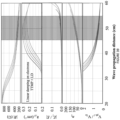
- Figure 35 illustrates exemplary power damping with the distance of wave propagation in an FRC plasma of the present FRC system 10.
- five rays are included with different n // between 4 and 6.
- Each ray has 200KW power at launching point.
- the region of significant power damping is between 30cm and 50cm.
- Figure 36 illustrates an exemplary power absorption profile in an FRC plasma of the present FRC system 10.
- Figure 36 there is observed significant power absorption on ions and electrons when HHFWs penetrate through the separatrix layer.
- heating electrons includes launching a plurality of high harmonic fast waves from one or more antennas into the FRC plasma in the confinement chamber at a launch angle from the mid-plane of the confinement chamber.
- the launch angle is in a range of about 15° to about 25° from the mid-plane of the confinement chamber.
- the launch angle is near but less than normal to a longitudinal axis of the confinement chamber.
- the one or more antennas is a phased array antenna with a plurality of straps.
- the high harmonic fast waves are fast waves in radio frequency ranges.
- heating the electrons including heating the electrons from about 150 eV to above about 1 keV.
- the method further includes maintaining the FRC at or about a constant value without decay and elevating the plasma electron temperature to above about 1.0 keV.
- the method further comprising generating a magnetic field within the confinement chamber with quasi dc coils extending about the confinement chamber and a mirror magnetic field within opposing ends of the confinement chamber with quasi dc mirror coils extending about the opposing ends of the confinement chamber.
- the method further comprising generating a magnetic field within the confinement chamber with quasi dc coils extending about the confinement chamber and a mirror magnetic field within opposing ends of the confinement chamber with quasi dc mirror coils extending about the opposing ends of the confinement chamber.
- forming the FRC includes forming a formation FRC in opposing first and second formation sections coupled to the confinement chamber and accelerating the formation FRC from the first and second formation sections towards the mid through plane of the confinement chamber where the two formation FRCs merge to form the FRC.
- forming the FRC includes one of forming a formation FRC while accelerating the formation FRC towards the mid-plane of the confinement chamber and forming a formation FRC then accelerating the formation FRC towards the mid through plane of the confinement chamber.
- accelerating the formation FRC from the first and second formation sections towards the mid-plane of the confinement chamber includes passing the formation FRC from the first and second formation sections through first and second inner divertors coupled to opposite ends of the confinement chamber interposing the confinement chamber and the first and second formation sections.
- passing the formation FRC from the first and second formation sections through first and second inner divertors includes inactivating the first and second inner divertors as the formation FRC from the first and second formation sections passes through the first and second inner divertors.
- the method further comprising guiding magnetic flux surfaces of the FRC into the first and second inner divertors.
- the method further comprising generating a magnetic field within the formation sections and first and second inner divertors with quasi-dc coils extending about the formation sections and divertors.
- the method further comprising generating a mirror magnetic field between the first and second formation sections and the first and second outer divertors with quasi-dc mirror coils.
- the method further comprising generating one of a magnetic dipole field and a magnetic quadrupole field within the chamber with saddle coils coupled to the chamber.
- the method further comprising conditioning the internal surfaces of the chamber and the internal surfaces of first and second formation sections, first and second divertors interposing the confinement chamber and the first and second formation sections, and first and second outer divertors coupled to the first and second formation sections with a gettering system.
- the gettering system includes one of a Titanium deposition system and a Lithium deposition system.
- the method further comprising axially injecting plasma into the FRC from axially mounted plasma guns.
Landscapes
- Physics & Mathematics (AREA)
- Engineering & Computer Science (AREA)
- Plasma & Fusion (AREA)
- General Engineering & Computer Science (AREA)
- High Energy & Nuclear Physics (AREA)
- Spectroscopy & Molecular Physics (AREA)
- Optics & Photonics (AREA)
- Chemical & Material Sciences (AREA)
- Chemical Kinetics & Catalysis (AREA)
- Plasma Technology (AREA)
- Organic Low-Molecular-Weight Compounds And Preparation Thereof (AREA)
- Particle Accelerators (AREA)
- Moulding By Coating Moulds (AREA)
Applications Claiming Priority (3)
| Application Number | Priority Date | Filing Date | Title |
|---|---|---|---|
| US201662422525P | 2016-11-15 | 2016-11-15 | |
| EP17872161.9A EP3542600A1 (en) | 2016-11-15 | 2017-11-15 | Systems and methods for improved sustainment of a high performance frc and high harmonic fast wave electron heating in a high performance frc |
| PCT/US2017/061860 WO2018093941A1 (en) | 2016-11-15 | 2017-11-15 | Systems and methods for improved sustainment of a high performance frc and high harmonic fast wave electron heating in a high performance frc |
Related Parent Applications (1)
| Application Number | Title | Priority Date | Filing Date |
|---|---|---|---|
| EP17872161.9A Division EP3542600A1 (en) | 2016-11-15 | 2017-11-15 | Systems and methods for improved sustainment of a high performance frc and high harmonic fast wave electron heating in a high performance frc |
Publications (2)
| Publication Number | Publication Date |
|---|---|
| EP3716286A1 EP3716286A1 (en) | 2020-09-30 |
| EP3716286B1 true EP3716286B1 (en) | 2025-07-09 |
Family
ID=62145824
Family Applications (2)
| Application Number | Title | Priority Date | Filing Date |
|---|---|---|---|
| EP20172605.6A Active EP3716286B1 (en) | 2016-11-15 | 2017-11-15 | Systems for improved sustainment of a high performance frc and high harmonic fast wave electron heating in a high performance frc |
| EP17872161.9A Withdrawn EP3542600A1 (en) | 2016-11-15 | 2017-11-15 | Systems and methods for improved sustainment of a high performance frc and high harmonic fast wave electron heating in a high performance frc |
Family Applications After (1)
| Application Number | Title | Priority Date | Filing Date |
|---|---|---|---|
| EP17872161.9A Withdrawn EP3542600A1 (en) | 2016-11-15 | 2017-11-15 | Systems and methods for improved sustainment of a high performance frc and high harmonic fast wave electron heating in a high performance frc |
Country Status (18)
| Country | Link |
|---|---|
| US (2) | US11335467B2 (enExample) |
| EP (2) | EP3716286B1 (enExample) |
| JP (2) | JP7266880B2 (enExample) |
| KR (1) | KR102590709B1 (enExample) |
| CN (2) | CN110024489B (enExample) |
| AU (2) | AU2017362979B2 (enExample) |
| CA (1) | CA3041895A1 (enExample) |
| CL (1) | CL2019001243A1 (enExample) |
| EA (1) | EA201991202A1 (enExample) |
| IL (1) | IL266612B2 (enExample) |
| MX (1) | MX2019005626A (enExample) |
| MY (1) | MY200927A (enExample) |
| PE (1) | PE20190836A1 (enExample) |
| PH (1) | PH12019500968A1 (enExample) |
| SA (1) | SA519401749B1 (enExample) |
| UA (1) | UA126673C2 (enExample) |
| WO (1) | WO2018093941A1 (enExample) |
| ZA (1) | ZA201902653B (enExample) |
Families Citing this family (18)
| Publication number | Priority date | Publication date | Assignee | Title |
|---|---|---|---|---|
| HUE047712T2 (hu) * | 2014-10-13 | 2020-05-28 | Tae Tech Inc | Összeállítás sûrû toroidok egyesítésére és összenyomására |
| KR102598740B1 (ko) * | 2015-05-12 | 2023-11-03 | 티에이이 테크놀로지스, 인크. | 원하지 않는 맴돌이 전류를 감소시키는 시스템 및 방법 |
| EP3716286B1 (en) * | 2016-11-15 | 2025-07-09 | TAE Technologies, Inc. | Systems for improved sustainment of a high performance frc and high harmonic fast wave electron heating in a high performance frc |
| DE102018204585A1 (de) * | 2017-03-31 | 2018-10-04 | centrotherm international AG | Plasmagenerator, Plasma-Behandlungsvorrichtung und Verfahren zum gepulsten Bereitstellen von elektrischer Leistung |
| US11037765B2 (en) * | 2018-07-03 | 2021-06-15 | Tokyo Electron Limited | Resonant structure for electron cyclotron resonant (ECR) plasma ionization |
| CN113812083B (zh) * | 2019-05-06 | 2024-04-16 | 谷歌有限责任公司 | 带电粒子束电力传输系统 |
| EP3819913A1 (en) * | 2019-11-11 | 2021-05-12 | JFP Jäderberg Fusion Power AB | Plasma confinement device and method for plasma confinement |
| CN115380627A (zh) * | 2020-01-13 | 2022-11-22 | 阿尔法能源技术公司 | 用于经由球马克合并和中性束注入来形成和保持高能高温frc等离子体的系统和方法 |
| CN117441412A (zh) * | 2021-04-08 | 2024-01-23 | 阿尔法能源技术公司 | 用于经由中性束注入来形成和保持高能和高温frc等离子体的系统及方法 |
| CN113543440B (zh) * | 2021-06-16 | 2022-06-24 | 核工业西南物理研究院 | 一种基于电子回旋波的阿尔芬模实时控制系统及方法 |
| US20230269860A1 (en) * | 2022-02-21 | 2023-08-24 | Leidos Engineering, LLC | High electron trapping ratio betatron |
| US12108501B2 (en) | 2022-04-13 | 2024-10-01 | Watlow Electric Manufacturing Company | Medium voltage bus system for electric circulation heaters |
| CN114689267B (zh) * | 2022-05-30 | 2022-08-05 | 中国空气动力研究与发展中心超高速空气动力研究所 | 等离子体电子密度分布的七通道微波干涉仪数据处理方法 |
| CN115798743B (zh) * | 2023-01-29 | 2023-05-30 | 中国科学院合肥物质科学研究院 | 一种电子回旋系统集成和运行的调试数据处理方法及装置 |
| WO2025142890A1 (ja) * | 2023-12-25 | 2025-07-03 | 学校法人日本大学 | ミラー型核融合装置 |
| CN117545157B (zh) * | 2024-01-09 | 2024-03-12 | 西南交通大学 | 一种用于测量等离子体电势和电场的诊断方法及系统 |
| US12255056B2 (en) | 2024-01-09 | 2025-03-18 | Southwest Jiaotong University | Diagnostic method and system for measuring potential and electric field of plasma |
| CN118380168B (zh) * | 2024-06-25 | 2024-09-06 | 中国科学院合肥物质科学研究院 | 一种中性束注入功率反馈控制方法 |
Family Cites Families (155)
| Publication number | Priority date | Publication date | Assignee | Title |
|---|---|---|---|---|
| US3120470A (en) | 1954-04-13 | 1964-02-04 | Donald H Imhoff | Method of producing neutrons |
| US3170841A (en) | 1954-07-14 | 1965-02-23 | Richard F Post | Pyrotron thermonuclear reactor and process |
| US3071525A (en) | 1958-08-19 | 1963-01-01 | Nicholas C Christofilos | Method and apparatus for producing thermonuclear reactions |
| US3036963A (en) | 1960-01-25 | 1962-05-29 | Nicholas C Christofilos | Method and apparatus for injecting and trapping electrons in a magnetic field |
| NL248482A (enExample) | 1960-02-26 | |||
| US3182213A (en) | 1961-06-01 | 1965-05-04 | Avco Corp | Magnetohydrodynamic generator |
| US3132996A (en) | 1962-12-10 | 1964-05-12 | William R Baker | Contra-rotating plasma system |
| US3386883A (en) | 1966-05-13 | 1968-06-04 | Itt | Method and apparatus for producing nuclear-fusion reactions |
| US3530036A (en) | 1967-12-15 | 1970-09-22 | Itt | Apparatus for generating fusion reactions |
| US3530497A (en) | 1968-04-24 | 1970-09-22 | Itt | Apparatus for generating fusion reactions |
| US3527977A (en) | 1968-06-03 | 1970-09-08 | Atomic Energy Commission | Moving electrons as an aid to initiating reactions in thermonuclear devices |
| US3577317A (en) | 1969-05-01 | 1971-05-04 | Atomic Energy Commission | Controlled fusion reactor |
| US3621310A (en) | 1969-05-30 | 1971-11-16 | Hitachi Ltd | Duct for magnetohydrodynamic thermal to electrical energy conversion apparatus |
| US3664921A (en) | 1969-10-16 | 1972-05-23 | Atomic Energy Commission | Proton e-layer astron for producing controlled fusion reactions |
| AT340010B (de) | 1970-05-21 | 1977-11-25 | Nowak Karl Ing | Einrichtung zur erzielung einer nuklearen reaktion mittels kunstlichem plasma vorzugsweise zur kontrollierten atomkernfusion |
| US3668065A (en) | 1970-09-15 | 1972-06-06 | Atomic Energy Commission | Apparatus for the conversion of high temperature plasma energy into electrical energy |
| US3663362A (en) | 1970-12-22 | 1972-05-16 | Atomic Energy Commission | Controlled fusion reactor |
| LU65432A1 (enExample) | 1972-05-29 | 1972-08-24 | ||
| US4233537A (en) | 1972-09-18 | 1980-11-11 | Rudolf Limpaecher | Multicusp plasma containment apparatus |
| US4182650A (en) | 1973-05-17 | 1980-01-08 | Fischer Albert G | Pulsed nuclear fusion reactor |
| US5041760A (en) | 1973-10-24 | 1991-08-20 | Koloc Paul M | Method and apparatus for generating and utilizing a compound plasma configuration |
| US5015432A (en) | 1973-10-24 | 1991-05-14 | Koloc Paul M | Method and apparatus for generating and utilizing a compound plasma configuration |
| US4010396A (en) | 1973-11-26 | 1977-03-01 | Kreidl Chemico Physical K.G. | Direct acting plasma accelerator |
| FR2270733A1 (en) | 1974-02-08 | 1975-12-05 | Thomson Csf | Magnetic field vehicle detector unit - receiver detects changes produced in an emitted magnetic field |
| US4098643A (en) | 1974-07-09 | 1978-07-04 | The United States Of America As Represented By The United States Department Of Energy | Dual-function magnetic structure for toroidal plasma devices |
| US4057462A (en) | 1975-02-26 | 1977-11-08 | The United States Of America As Represented By The United States Energy Research And Development Administration | Radio frequency sustained ion energy |
| US4054846A (en) | 1975-04-02 | 1977-10-18 | Bell Telephone Laboratories, Incorporated | Transverse-excitation laser with preionization |
| US4065351A (en) * | 1976-03-25 | 1977-12-27 | The United States Of America As Represented By The United States Energy Research And Development Administration | Particle beam injection system |
| US4166760A (en) | 1977-10-04 | 1979-09-04 | The United States Of America As Represented By The United States Department Of Energy | Plasma confinement apparatus using solenoidal and mirror coils |
| US4347621A (en) | 1977-10-25 | 1982-08-31 | Environmental Institute Of Michigan | Trochoidal nuclear fusion reactor |
| US4303467A (en) | 1977-11-11 | 1981-12-01 | Branson International Plasma Corporation | Process and gas for treatment of semiconductor devices |
| US4274919A (en) | 1977-11-14 | 1981-06-23 | General Atomic Company | Systems for merging of toroidal plasmas |
| US4202725A (en) | 1978-03-08 | 1980-05-13 | Jarnagin William S | Converging beam fusion system |
| US4189346A (en) | 1978-03-16 | 1980-02-19 | Jarnagin William S | Operationally confined nuclear fusion system |
| US4246067A (en) | 1978-08-30 | 1981-01-20 | Linlor William I | Thermonuclear fusion system |
| US4267488A (en) | 1979-01-05 | 1981-05-12 | Trisops, Inc. | Containment of plasmas at thermonuclear temperatures |
| US4397810A (en) | 1979-03-16 | 1983-08-09 | Energy Profiles, Inc. | Compressed beam directed particle nuclear energy generator |
| US4314879A (en) | 1979-03-22 | 1982-02-09 | The United States Of America As Represented By The United States Department Of Energy | Production of field-reversed mirror plasma with a coaxial plasma gun |
| US4416845A (en) | 1979-08-02 | 1983-11-22 | Energy Profiles, Inc. | Control for orbiting charged particles |
| JPS5829568B2 (ja) | 1979-12-07 | 1983-06-23 | 岩崎通信機株式会社 | 2ビ−ム1電子銃陰極線管 |
| US4548782A (en) | 1980-03-27 | 1985-10-22 | The United States Of America As Represented By The Secretary Of The Navy | Tokamak plasma heating with intense, pulsed ion beams |
| US4390494A (en) | 1980-04-07 | 1983-06-28 | Energy Profiles, Inc. | Directed beam fusion reaction with ion spin alignment |
| US4350927A (en) | 1980-05-23 | 1982-09-21 | The United States Of America As Represented By The United States Department Of Energy | Means for the focusing and acceleration of parallel beams of charged particles |
| US4317057A (en) | 1980-06-16 | 1982-02-23 | Bazarov Georgy P | Channel of series-type magnetohydrodynamic generator |
| US4434130A (en) | 1980-11-03 | 1984-02-28 | Energy Profiles, Inc. | Electron space charge channeling for focusing ion beams |
| US4584160A (en) | 1981-09-30 | 1986-04-22 | Tokyo Shibaura Denki Kabushiki Kaisha | Plasma devices |
| US4543231A (en) | 1981-12-14 | 1985-09-24 | Ga Technologies Inc. | Multiple pinch method and apparatus for producing average magnetic well in plasma confinement |
| US4560528A (en) | 1982-04-12 | 1985-12-24 | Ga Technologies Inc. | Method and apparatus for producing average magnetic well in a reversed field pinch |
| JPH06105597B2 (ja) | 1982-08-30 | 1994-12-21 | 株式会社日立製作所 | マイクロ波プラズマ源 |
| JPS5960899A (ja) | 1982-09-29 | 1984-04-06 | 株式会社東芝 | イオン・エネルギ−回収装置 |
| US4618470A (en) | 1982-12-01 | 1986-10-21 | Austin N. Stanton | Magnetic confinement nuclear energy generator |
| US4483737A (en) | 1983-01-31 | 1984-11-20 | University Of Cincinnati | Method and apparatus for plasma etching a substrate |
| US4601871A (en) | 1983-05-17 | 1986-07-22 | The United States Of America As Represented By The United States Department Of Energy | Steady state compact toroidal plasma production |
| USH235H (en) | 1983-09-26 | 1987-03-03 | The United States Of America As Represented By The United States Department Of Energy | In-situ determination of energy species yields of intense particle beams |
| JPS60165095A (ja) * | 1984-02-07 | 1985-08-28 | 株式会社日立製作所 | 核融合装置のプラズマ加熱制御装置 |
| US4650631A (en) | 1984-05-14 | 1987-03-17 | The University Of Iowa Research Foundation | Injection, containment and heating device for fusion plasmas |
| US4639348A (en) | 1984-11-13 | 1987-01-27 | Jarnagin William S | Recyclotron III, a recirculating plasma fusion system |
| US4615755A (en) | 1985-08-07 | 1986-10-07 | The Perkin-Elmer Corporation | Wafer cooling and temperature control for a plasma etching system |
| US4826646A (en) | 1985-10-29 | 1989-05-02 | Energy/Matter Conversion Corporation, Inc. | Method and apparatus for controlling charged particles |
| US4630939A (en) | 1985-11-15 | 1986-12-23 | The Dow Chemical Company | Temperature measuring apparatus |
| SE450060B (sv) | 1985-11-27 | 1987-06-01 | Rolf Lennart Stenbacka | Forfarande for att astadkomma fusionsreaktioner, samt anordning for fusionsreaktor |
| US4687616A (en) | 1986-01-15 | 1987-08-18 | The United States Of America As Represented By The United States Department Of Energy | Method and apparatus for preventing cyclotron breakdown in partially evacuated waveguide |
| US4894199A (en) | 1986-06-11 | 1990-01-16 | Norman Rostoker | Beam fusion device and method |
| DK556887D0 (da) | 1987-10-23 | 1987-10-23 | Risoe Forskningscenter | Fremgangsmaade til fremstilling af en pille og injektor til injektion af saadan pille |
| EP0438724B1 (en) | 1990-01-22 | 1996-05-08 | Werner K. Dipl.-Ing. Steudtner | Fusion reactor |
| US5160695A (en) | 1990-02-08 | 1992-11-03 | Qed, Inc. | Method and apparatus for creating and controlling nuclear fusion reactions |
| US5311028A (en) | 1990-08-29 | 1994-05-10 | Nissin Electric Co., Ltd. | System and method for producing oscillating magnetic fields in working gaps useful for irradiating a surface with atomic and molecular ions |
| US5122662A (en) | 1990-10-16 | 1992-06-16 | Schlumberger Technology Corporation | Circular induction accelerator for borehole logging |
| US5206516A (en) | 1991-04-29 | 1993-04-27 | International Business Machines Corporation | Low energy, steered ion beam deposition system having high current at low pressure |
| US6488807B1 (en) | 1991-06-27 | 2002-12-03 | Applied Materials, Inc. | Magnetic confinement in a plasma reactor having an RF bias electrode |
| US5207760A (en) | 1991-07-23 | 1993-05-04 | Trw Inc. | Multi-megawatt pulsed inductive thruster |
| JP3080751B2 (ja) * | 1992-01-23 | 2000-08-28 | 株式会社東芝 | 高周波加熱装置 |
| US5323442A (en) | 1992-02-28 | 1994-06-21 | Ruxam, Inc. | Microwave X-ray source and methods of use |
| US5502354A (en) | 1992-07-31 | 1996-03-26 | Correa; Paulo N. | Direct current energized pulse generator utilizing autogenous cyclical pulsed abnormal glow discharges |
| RU2056649C1 (ru) | 1992-10-29 | 1996-03-20 | Сергей Николаевич Столбов | Способ управляемого термоядерного синтеза и управляемый термоядерный реактор для его осуществления |
| US5339336A (en) | 1993-02-17 | 1994-08-16 | Cornell Research Foundation, Inc. | High current ion ring accelerator |
| FR2705584B1 (fr) | 1993-05-26 | 1995-06-30 | Commissariat Energie Atomique | Dispositif de séparation isotopique par résonance cyclotronique ionique. |
| US5473165A (en) | 1993-11-16 | 1995-12-05 | Stinnett; Regan W. | Method and apparatus for altering material |
| DE69421157T2 (de) | 1993-12-21 | 2000-04-06 | Sumitomo Heavy Industries, Ltd. | Plasmastrahl-Erzeugungsverfahren und Vorrichtung die einen Hochleistungsplasmastrahl erzeugen Kann |
| US5537005A (en) | 1994-05-13 | 1996-07-16 | Hughes Aircraft | High-current, low-pressure plasma-cathode electron gun |
| US5420425A (en) | 1994-05-27 | 1995-05-30 | Finnigan Corporation | Ion trap mass spectrometer system and method |
| US5656519A (en) | 1995-02-14 | 1997-08-12 | Nec Corporation | Method for manufacturing salicide semiconductor device |
| US5653811A (en) | 1995-07-19 | 1997-08-05 | Chan; Chung | System for the plasma treatment of large area substrates |
| US20040213368A1 (en) | 1995-09-11 | 2004-10-28 | Norman Rostoker | Fusion reactor that produces net power from the p-b11 reaction |
| EP0876663B1 (en) | 1995-09-25 | 2003-11-12 | KOLOC, Paul M. | Apparatus for generating a plasma |
| JP3385327B2 (ja) | 1995-12-13 | 2003-03-10 | 株式会社日立製作所 | 三次元四重極質量分析装置 |
| US5764715A (en) | 1996-02-20 | 1998-06-09 | Sandia Corporation | Method and apparatus for transmutation of atomic nuclei |
| KR100275597B1 (ko) | 1996-02-23 | 2000-12-15 | 나카네 히사시 | 플리즈마처리장치 |
| US6000360A (en) | 1996-07-03 | 1999-12-14 | Tokyo Electron Limited | Plasma processing apparatus |
| US5811201A (en) | 1996-08-16 | 1998-09-22 | Southern California Edison Company | Power generation system utilizing turbine and fuel cell |
| US5923716A (en) | 1996-11-07 | 1999-07-13 | Meacham; G. B. Kirby | Plasma extrusion dynamo and methods related thereto |
| JP3582287B2 (ja) | 1997-03-26 | 2004-10-27 | 株式会社日立製作所 | エッチング装置 |
| JPH10335096A (ja) | 1997-06-03 | 1998-12-18 | Hitachi Ltd | プラズマ処理装置 |
| US6628740B2 (en) | 1997-10-17 | 2003-09-30 | The Regents Of The University Of California | Controlled fusion in a field reversed configuration and direct energy conversion |
| US6894446B2 (en) | 1997-10-17 | 2005-05-17 | The Regents Of The University Of California | Controlled fusion in a field reversed configuration and direct energy conversion |
| US6271529B1 (en) | 1997-12-01 | 2001-08-07 | Ebara Corporation | Ion implantation with charge neutralization |
| US6390019B1 (en) | 1998-06-11 | 2002-05-21 | Applied Materials, Inc. | Chamber having improved process monitoring window |
| FR2780499B1 (fr) | 1998-06-25 | 2000-08-18 | Schlumberger Services Petrol | Dispositifs de caracterisation de l'ecoulement d'un fluide polyphasique |
| DE19929278A1 (de) | 1998-06-26 | 2000-02-17 | Nissin Electric Co Ltd | Verfahren zum Implantieren negativer Wasserstoffionen und Implantierungseinrichtung |
| US6255648B1 (en) | 1998-10-16 | 2001-07-03 | Applied Automation, Inc. | Programmed electron flux |
| US6248251B1 (en) | 1999-02-19 | 2001-06-19 | Tokyo Electron Limited | Apparatus and method for electrostatically shielding an inductively coupled RF plasma source and facilitating ignition of a plasma |
| US6755086B2 (en) | 1999-06-17 | 2004-06-29 | Schlumberger Technology Corporation | Flow meter for multi-phase mixtures |
| US6322706B1 (en) | 1999-07-14 | 2001-11-27 | Archimedes Technology Group, Inc. | Radial plasma mass filter |
| US6452168B1 (en) | 1999-09-15 | 2002-09-17 | Ut-Battelle, Llc | Apparatus and methods for continuous beam fourier transform mass spectrometry |
| DE10060002B4 (de) | 1999-12-07 | 2016-01-28 | Komatsu Ltd. | Vorrichtung zur Oberflächenbehandlung |
| US6593539B1 (en) | 2000-02-25 | 2003-07-15 | George Miley | Apparatus and methods for controlling charged particles |
| US6408052B1 (en) | 2000-04-06 | 2002-06-18 | Mcgeoch Malcolm W. | Z-pinch plasma X-ray source using surface discharge preionization |
| US6593570B2 (en) | 2000-05-24 | 2003-07-15 | Agilent Technologies, Inc. | Ion optic components for mass spectrometers |
| CN101018444B (zh) * | 2001-02-01 | 2011-01-26 | 加州大学评议会 | 场反向配置中的等离子体的磁和静电约束 |
| US6664740B2 (en) * | 2001-02-01 | 2003-12-16 | The Regents Of The University Of California | Formation of a field reversed configuration for magnetic and electrostatic confinement of plasma |
| US6611106B2 (en) | 2001-03-19 | 2003-08-26 | The Regents Of The University Of California | Controlled fusion in a field reversed configuration and direct energy conversion |
| GB0131097D0 (en) | 2001-12-31 | 2002-02-13 | Applied Materials Inc | Ion sources |
| US6911649B2 (en) | 2002-06-21 | 2005-06-28 | Battelle Memorial Institute | Particle generator |
| US9123512B2 (en) * | 2005-03-07 | 2015-09-01 | The Regents Of The Unviersity Of California | RF current drive for plasma electric generation system |
| US8031824B2 (en) * | 2005-03-07 | 2011-10-04 | Regents Of The University Of California | Inductive plasma source for plasma electric generation system |
| EA013826B1 (ru) | 2005-03-07 | 2010-08-30 | Дзе Риджентс Оф Дзе Юниверсити Оф Калифорния | Система для выработки электроэнергии из плазмы |
| US9607719B2 (en) * | 2005-03-07 | 2017-03-28 | The Regents Of The University Of California | Vacuum chamber for plasma electric generation system |
| SI1856702T1 (sl) | 2005-03-07 | 2012-11-30 | Univ California | Plazemski sistem za generiranje elektrike |
| US7115887B1 (en) | 2005-03-15 | 2006-10-03 | The United States Of America As Represented By The United States Department Of Energy | Method for generating extreme ultraviolet with mather-type plasma accelerators for use in Extreme Ultraviolet Lithography |
| JP4831600B2 (ja) * | 2005-08-05 | 2011-12-07 | 独立行政法人日本原子力研究開発機構 | 高周波加熱装置用直線駆動アンテナ |
| US20080226011A1 (en) | 2005-10-04 | 2008-09-18 | Barnes Daniel C | Plasma Centrifuge Heat Engine Beam Fusion Reactor |
| CN101320599A (zh) | 2007-06-06 | 2008-12-10 | 高晓达 | 通过极限环螺旋扇形注入区的束流连续注入方法 |
| US8368636B2 (en) | 2007-09-21 | 2013-02-05 | Point Somee Limited Liability Company | Regulation of wavelength shift and perceived color of solid state lighting with intensity variation |
| US20100020913A1 (en) * | 2008-07-22 | 2010-01-28 | Alexander Mozgovoy | Method for obtainging plasma |
| GB2475634B (en) | 2008-09-18 | 2013-04-10 | Craftsmen Corp E | Configurable LED driver/dimmer for solid state lighting applications |
| KR101541576B1 (ko) | 2009-02-04 | 2015-08-03 | 제너럴 퓨전 아이엔씨. | 플라스마를 압축하기 위한 시스템 및 방법 |
| WO2010093981A2 (en) * | 2009-02-12 | 2010-08-19 | Msnw, Llc | Method and apparatus for the generation, heating and/or compression of plasmoids and/or recovery of energy therefrom |
| US8569956B2 (en) | 2009-06-04 | 2013-10-29 | Point Somee Limited Liability Company | Apparatus, method and system for providing AC line power to lighting devices |
| US8193738B2 (en) | 2009-08-07 | 2012-06-05 | Phihong Technology Co., Ltd. | Dimmable LED device with low ripple current and driving circuit thereof |
| EP2295293B2 (de) * | 2009-09-11 | 2019-02-20 | Weidplas GmbH | Verfahren zum Herstellen eines Bauteils mit einem flächigen Dekorelement und Bauteil mit einem flächigen Dekorelement |
| US8760078B2 (en) | 2010-10-04 | 2014-06-24 | Earl W. McCune, Jr. | Power conversion and control systems and methods for solid-state lighting |
| US8587215B2 (en) | 2011-05-05 | 2013-11-19 | General Electric Company | Self-dimming OLED lighting system and control method |
| CN103428953B (zh) | 2012-05-17 | 2016-03-16 | 昂宝电子(上海)有限公司 | 用于利用系统控制器进行调光控制的系统和方法 |
| CA2854823C (en) * | 2011-11-07 | 2020-04-14 | Helion Energy, Inc. | Apparatus, systems and methods for fusion based power generation and engine thrust generation |
| SG10201704299XA (en) * | 2011-11-14 | 2017-06-29 | Univ California | Systems and methods for forming and maintaining a high performance frc |
| US9078327B2 (en) | 2012-03-05 | 2015-07-07 | Luxera, Inc. | Apparatus and method for dimming signal generation for a distributed solid state lighting system |
| US20130249431A1 (en) | 2012-03-05 | 2013-09-26 | Luxera, Inc. | Dimmable Hybrid Adapter for a Solid State Lighting System, Apparatus and Method |
| US9767925B2 (en) | 2012-03-23 | 2017-09-19 | The Trustees Of Princeton University | Method, apparatus, and system to reduce neutron production in small clean fusion reactors |
| RU2638958C2 (ru) | 2012-11-06 | 2017-12-19 | Филипс Лайтинг Холдинг Б.В. | Схемное устройство и сид лампа, содержащая это схемное устройство |
| CN103024994B (zh) | 2012-11-12 | 2016-06-01 | 昂宝电子(上海)有限公司 | 使用triac调光器的调光控制系统和方法 |
| US9192002B2 (en) | 2012-11-20 | 2015-11-17 | Isine, Inc. | AC/DC conversion bypass power delivery |
| WO2014114986A1 (en) | 2013-01-25 | 2014-07-31 | L Ferreira Jr Moacir | Multiphase nuclear fusion reactor |
| CN110335737A (zh) | 2013-02-11 | 2019-10-15 | 加州大学评议会 | 分数匝线圈绕组 |
| US9591740B2 (en) * | 2013-03-08 | 2017-03-07 | Tri Alpha Energy, Inc. | Negative ion-based neutral beam injector |
| UA125164C2 (uk) | 2013-09-24 | 2022-01-26 | ТАЄ Текнолоджіс, Інк. | Системи і способи формування і підтримання високоефективної конфігурації з оберненим полем |
| CN104066254B (zh) | 2014-07-08 | 2017-01-04 | 昂宝电子(上海)有限公司 | 使用triac调光器进行智能调光控制的系统和方法 |
| KR20160014379A (ko) | 2014-07-29 | 2016-02-11 | 주식회사 실리콘웍스 | 조명 장치 |
| KR102257718B1 (ko) | 2014-10-01 | 2021-05-28 | 매그나칩 반도체 유한회사 | 발광 다이오드 구동 회로 및 이를 포함하는 발광 다이오드 조명 장치 |
| HUE047712T2 (hu) * | 2014-10-13 | 2020-05-28 | Tae Tech Inc | Összeállítás sûrû toroidok egyesítésére és összenyomására |
| HRP20221278T1 (hr) * | 2014-10-30 | 2022-12-23 | Tae Technologies, Inc. | Sustavi za formiranje i održavanje frc visokih performansi |
| TWI629916B (zh) | 2014-12-10 | 2018-07-11 | 隆達電子股份有限公司 | 發光裝置與發光二極體電路 |
| WO2016138068A1 (en) * | 2015-02-24 | 2016-09-01 | The Trustees Of Princeton University | System and method for small, clean, steady-state fusion reactors |
| MY191665A (en) * | 2015-11-13 | 2022-07-06 | Tae Tech Inc | Systems and methods for frc plasma position stability |
| US10326370B2 (en) | 2016-06-02 | 2019-06-18 | Semiconductor Components Industries, Llc | Controlling output voltage for power converter |
| EP3716286B1 (en) * | 2016-11-15 | 2025-07-09 | TAE Technologies, Inc. | Systems for improved sustainment of a high performance frc and high harmonic fast wave electron heating in a high performance frc |
-
2017
- 2017-11-15 EP EP20172605.6A patent/EP3716286B1/en active Active
- 2017-11-15 CN CN201780070992.7A patent/CN110024489B/zh active Active
- 2017-11-15 EA EA201991202A patent/EA201991202A1/ru unknown
- 2017-11-15 PE PE2019000982A patent/PE20190836A1/es unknown
- 2017-11-15 UA UAA201906702A patent/UA126673C2/uk unknown
- 2017-11-15 MY MYPI2019002354A patent/MY200927A/en unknown
- 2017-11-15 WO PCT/US2017/061860 patent/WO2018093941A1/en not_active Ceased
- 2017-11-15 CN CN202310141107.7A patent/CN116170928A/zh active Pending
- 2017-11-15 JP JP2019524871A patent/JP7266880B2/ja active Active
- 2017-11-15 AU AU2017362979A patent/AU2017362979B2/en not_active Ceased
- 2017-11-15 EP EP17872161.9A patent/EP3542600A1/en not_active Withdrawn
- 2017-11-15 IL IL266612A patent/IL266612B2/en unknown
- 2017-11-15 KR KR1020197017250A patent/KR102590709B1/ko active Active
- 2017-11-15 MX MX2019005626A patent/MX2019005626A/es unknown
- 2017-11-15 CA CA3041895A patent/CA3041895A1/en active Pending
-
2019
- 2019-04-26 ZA ZA2019/02653A patent/ZA201902653B/en unknown
- 2019-04-30 PH PH12019500968A patent/PH12019500968A1/en unknown
- 2019-04-30 US US16/399,521 patent/US11335467B2/en active Active
- 2019-05-06 CL CL2019001243A patent/CL2019001243A1/es unknown
- 2019-05-08 SA SA519401749A patent/SA519401749B1/ar unknown
-
2022
- 2022-03-10 US US17/692,106 patent/US11929182B2/en active Active
- 2022-05-16 JP JP2022080208A patent/JP2022105221A/ja active Pending
-
2023
- 2023-01-18 AU AU2023200243A patent/AU2023200243A1/en not_active Abandoned
Also Published As
| Publication number | Publication date |
|---|---|
| MY200927A (en) | 2024-01-24 |
| KR20190085054A (ko) | 2019-07-17 |
| EP3716286A1 (en) | 2020-09-30 |
| KR102590709B1 (ko) | 2023-10-17 |
| AU2017362979A1 (en) | 2019-05-23 |
| CN110024489B (zh) | 2023-03-10 |
| AU2017362979B2 (en) | 2022-10-27 |
| CN110024489A (zh) | 2019-07-16 |
| PE20190836A1 (es) | 2019-06-17 |
| UA126673C2 (uk) | 2023-01-11 |
| US20220277861A1 (en) | 2022-09-01 |
| EA201991202A1 (ru) | 2019-10-31 |
| CA3041895A1 (en) | 2018-05-24 |
| CL2019001243A1 (es) | 2019-09-13 |
| PH12019500968A1 (en) | 2019-11-11 |
| WO2018093941A1 (en) | 2018-05-24 |
| JP2022105221A (ja) | 2022-07-12 |
| US20190326023A1 (en) | 2019-10-24 |
| AU2023200243A1 (en) | 2023-02-16 |
| BR112019009744A2 (pt) | 2019-08-13 |
| IL266612B1 (en) | 2023-12-01 |
| MX2019005626A (es) | 2019-07-04 |
| JP2019537722A (ja) | 2019-12-26 |
| US11929182B2 (en) | 2024-03-12 |
| JP7266880B2 (ja) | 2023-05-01 |
| ZA201902653B (en) | 2020-08-26 |
| SA519401749B1 (ar) | 2022-06-16 |
| CN116170928A (zh) | 2023-05-26 |
| EP3542600A1 (en) | 2019-09-25 |
| US11335467B2 (en) | 2022-05-17 |
| IL266612B2 (en) | 2024-04-01 |
| IL266612A (en) | 2019-07-31 |
Similar Documents
| Publication | Publication Date | Title |
|---|---|---|
| US11929182B2 (en) | Systems and methods for improved sustainment of a high performance FRC and high harmonic fast wave electron heating in a high performance FRC | |
| US11337294B2 (en) | Systems and methods for forming and maintaining a high performance FRC | |
| US11373763B2 (en) | Systems and methods for forming and maintaining a high performance FRC | |
| EP2780913A2 (en) | Systems and methods for forming and maintaining a high performance frc | |
| HK40012712B (en) | Systems for forming and maintaining a high performance frc | |
| HK40012712A (en) | Systems for forming and maintaining a high performance frc | |
| NZ757525B2 (en) | Systems and methods for forming and maintaining a high performance frc |
Legal Events
| Date | Code | Title | Description |
|---|---|---|---|
| PUAI | Public reference made under article 153(3) epc to a published international application that has entered the european phase |
Free format text: ORIGINAL CODE: 0009012 |
|
| STAA | Information on the status of an ep patent application or granted ep patent |
Free format text: STATUS: THE APPLICATION HAS BEEN PUBLISHED |
|
| AC | Divisional application: reference to earlier application |
Ref document number: 3542600 Country of ref document: EP Kind code of ref document: P |
|
| AK | Designated contracting states |
Kind code of ref document: A1 Designated state(s): AL AT BE BG CH CY CZ DE DK EE ES FI FR GB GR HR HU IE IS IT LI LT LU LV MC MK MT NL NO PL PT RO RS SE SI SK SM TR |
|
| STAA | Information on the status of an ep patent application or granted ep patent |
Free format text: STATUS: REQUEST FOR EXAMINATION WAS MADE |
|
| 17P | Request for examination filed |
Effective date: 20210330 |
|
| RBV | Designated contracting states (corrected) |
Designated state(s): AL AT BE BG CH CY CZ DE DK EE ES FI FR GB GR HR HU IE IS IT LI LT LU LV MC MK MT NL NO PL PT RO RS SE SI SK SM TR |
|
| STAA | Information on the status of an ep patent application or granted ep patent |
Free format text: STATUS: EXAMINATION IS IN PROGRESS |
|
| 17Q | First examination report despatched |
Effective date: 20220311 |
|
| P01 | Opt-out of the competence of the unified patent court (upc) registered |
Effective date: 20230519 |
|
| REG | Reference to a national code |
Ref country code: DE Ref legal event code: R079 Free format text: PREVIOUS MAIN CLASS: G21B0001000000 Ipc: G21B0001110000 Ref country code: DE Ref legal event code: R079 Ref document number: 602017090534 Country of ref document: DE Free format text: PREVIOUS MAIN CLASS: G21B0001000000 Ipc: G21B0001110000 |
|
| GRAP | Despatch of communication of intention to grant a patent |
Free format text: ORIGINAL CODE: EPIDOSNIGR1 |
|
| STAA | Information on the status of an ep patent application or granted ep patent |
Free format text: STATUS: GRANT OF PATENT IS INTENDED |
|
| RIC1 | Information provided on ipc code assigned before grant |
Ipc: H05H 1/14 20060101ALI20240510BHEP Ipc: G21B 1/05 20060101ALI20240510BHEP Ipc: G21B 1/11 20060101AFI20240510BHEP |
|
| INTG | Intention to grant announced |
Effective date: 20240605 |
|
| GRAS | Grant fee paid |
Free format text: ORIGINAL CODE: EPIDOSNIGR3 |
|
| GRAA | (expected) grant |
Free format text: ORIGINAL CODE: 0009210 |
|
| STAA | Information on the status of an ep patent application or granted ep patent |
Free format text: STATUS: THE PATENT HAS BEEN GRANTED |
|
| AC | Divisional application: reference to earlier application |
Ref document number: 3542600 Country of ref document: EP Kind code of ref document: P |
|
| AK | Designated contracting states |
Kind code of ref document: B1 Designated state(s): AL AT BE BG CH CY CZ DE DK EE ES FI FR GB GR HR HU IE IS IT LI LT LU LV MC MK MT NL NO PL PT RO RS SE SI SK SM TR |
|
| REG | Reference to a national code |
Ref country code: GB Ref legal event code: FG4D |
|
| REG | Reference to a national code |
Ref country code: CH Ref legal event code: EP |
|
| REG | Reference to a national code |
Ref country code: IE Ref legal event code: FG4D |
|
| REG | Reference to a national code |
Ref country code: DE Ref legal event code: R096 Ref document number: 602017090534 Country of ref document: DE |
|
| REG | Reference to a national code |
Ref country code: NL Ref legal event code: MP Effective date: 20250709 |
|
| PG25 | Lapsed in a contracting state [announced via postgrant information from national office to epo] |
Ref country code: PT Free format text: LAPSE BECAUSE OF FAILURE TO SUBMIT A TRANSLATION OF THE DESCRIPTION OR TO PAY THE FEE WITHIN THE PRESCRIBED TIME-LIMIT Effective date: 20251110 |
|
| PG25 | Lapsed in a contracting state [announced via postgrant information from national office to epo] |
Ref country code: NL Free format text: LAPSE BECAUSE OF FAILURE TO SUBMIT A TRANSLATION OF THE DESCRIPTION OR TO PAY THE FEE WITHIN THE PRESCRIBED TIME-LIMIT Effective date: 20250709 |
|
| REG | Reference to a national code |
Ref country code: AT Ref legal event code: MK05 Ref document number: 1812684 Country of ref document: AT Kind code of ref document: T Effective date: 20250709 |
|
| PG25 | Lapsed in a contracting state [announced via postgrant information from national office to epo] |
Ref country code: IS Free format text: LAPSE BECAUSE OF FAILURE TO SUBMIT A TRANSLATION OF THE DESCRIPTION OR TO PAY THE FEE WITHIN THE PRESCRIBED TIME-LIMIT Effective date: 20251109 |
|
| PGFP | Annual fee paid to national office [announced via postgrant information from national office to epo] |
Ref country code: DE Payment date: 20251201 Year of fee payment: 9 |
|
| PGFP | Annual fee paid to national office [announced via postgrant information from national office to epo] |
Ref country code: GB Payment date: 20251202 Year of fee payment: 9 |
|
| PG25 | Lapsed in a contracting state [announced via postgrant information from national office to epo] |
Ref country code: NO Free format text: LAPSE BECAUSE OF FAILURE TO SUBMIT A TRANSLATION OF THE DESCRIPTION OR TO PAY THE FEE WITHIN THE PRESCRIBED TIME-LIMIT Effective date: 20251009 |
|
| REG | Reference to a national code |
Ref country code: LT Ref legal event code: MG9D |
|
| PG25 | Lapsed in a contracting state [announced via postgrant information from national office to epo] |
Ref country code: AT Free format text: LAPSE BECAUSE OF FAILURE TO SUBMIT A TRANSLATION OF THE DESCRIPTION OR TO PAY THE FEE WITHIN THE PRESCRIBED TIME-LIMIT Effective date: 20250709 |
|
| PG25 | Lapsed in a contracting state [announced via postgrant information from national office to epo] |
Ref country code: FI Free format text: LAPSE BECAUSE OF FAILURE TO SUBMIT A TRANSLATION OF THE DESCRIPTION OR TO PAY THE FEE WITHIN THE PRESCRIBED TIME-LIMIT Effective date: 20250709 |
|
| PG25 | Lapsed in a contracting state [announced via postgrant information from national office to epo] |
Ref country code: HR Free format text: LAPSE BECAUSE OF FAILURE TO SUBMIT A TRANSLATION OF THE DESCRIPTION OR TO PAY THE FEE WITHIN THE PRESCRIBED TIME-LIMIT Effective date: 20250709 |
|
| PGFP | Annual fee paid to national office [announced via postgrant information from national office to epo] |
Ref country code: FR Payment date: 20251201 Year of fee payment: 9 |
|
| PG25 | Lapsed in a contracting state [announced via postgrant information from national office to epo] |
Ref country code: GR Free format text: LAPSE BECAUSE OF FAILURE TO SUBMIT A TRANSLATION OF THE DESCRIPTION OR TO PAY THE FEE WITHIN THE PRESCRIBED TIME-LIMIT Effective date: 20251010 |
|
| PG25 | Lapsed in a contracting state [announced via postgrant information from national office to epo] |
Ref country code: SE Free format text: LAPSE BECAUSE OF FAILURE TO SUBMIT A TRANSLATION OF THE DESCRIPTION OR TO PAY THE FEE WITHIN THE PRESCRIBED TIME-LIMIT Effective date: 20250709 |
|
| PG25 | Lapsed in a contracting state [announced via postgrant information from national office to epo] |
Ref country code: LV Free format text: LAPSE BECAUSE OF FAILURE TO SUBMIT A TRANSLATION OF THE DESCRIPTION OR TO PAY THE FEE WITHIN THE PRESCRIBED TIME-LIMIT Effective date: 20250709 |
|
| PG25 | Lapsed in a contracting state [announced via postgrant information from national office to epo] |
Ref country code: PL Free format text: LAPSE BECAUSE OF FAILURE TO SUBMIT A TRANSLATION OF THE DESCRIPTION OR TO PAY THE FEE WITHIN THE PRESCRIBED TIME-LIMIT Effective date: 20250709 Ref country code: BG Free format text: LAPSE BECAUSE OF FAILURE TO SUBMIT A TRANSLATION OF THE DESCRIPTION OR TO PAY THE FEE WITHIN THE PRESCRIBED TIME-LIMIT Effective date: 20250709 |
|
| PG25 | Lapsed in a contracting state [announced via postgrant information from national office to epo] |
Ref country code: RS Free format text: LAPSE BECAUSE OF FAILURE TO SUBMIT A TRANSLATION OF THE DESCRIPTION OR TO PAY THE FEE WITHIN THE PRESCRIBED TIME-LIMIT Effective date: 20251009 |
|
| PG25 | Lapsed in a contracting state [announced via postgrant information from national office to epo] |
Ref country code: ES Free format text: LAPSE BECAUSE OF FAILURE TO SUBMIT A TRANSLATION OF THE DESCRIPTION OR TO PAY THE FEE WITHIN THE PRESCRIBED TIME-LIMIT Effective date: 20250709 |
|
| PG25 | Lapsed in a contracting state [announced via postgrant information from national office to epo] |
Ref country code: RO Free format text: LAPSE BECAUSE OF FAILURE TO SUBMIT A TRANSLATION OF THE DESCRIPTION OR TO PAY THE FEE WITHIN THE PRESCRIBED TIME-LIMIT Effective date: 20250709 |
|
| PG25 | Lapsed in a contracting state [announced via postgrant information from national office to epo] |
Ref country code: SM Free format text: LAPSE BECAUSE OF FAILURE TO SUBMIT A TRANSLATION OF THE DESCRIPTION OR TO PAY THE FEE WITHIN THE PRESCRIBED TIME-LIMIT Effective date: 20250709 |
|
| PG25 | Lapsed in a contracting state [announced via postgrant information from national office to epo] |
Ref country code: DK Free format text: LAPSE BECAUSE OF FAILURE TO SUBMIT A TRANSLATION OF THE DESCRIPTION OR TO PAY THE FEE WITHIN THE PRESCRIBED TIME-LIMIT Effective date: 20250709 |
|
| PG25 | Lapsed in a contracting state [announced via postgrant information from national office to epo] |
Ref country code: IT Free format text: LAPSE BECAUSE OF FAILURE TO SUBMIT A TRANSLATION OF THE DESCRIPTION OR TO PAY THE FEE WITHIN THE PRESCRIBED TIME-LIMIT Effective date: 20250709 |
|
| PG25 | Lapsed in a contracting state [announced via postgrant information from national office to epo] |
Ref country code: CZ Free format text: LAPSE BECAUSE OF FAILURE TO SUBMIT A TRANSLATION OF THE DESCRIPTION OR TO PAY THE FEE WITHIN THE PRESCRIBED TIME-LIMIT Effective date: 20250709 |
|
| PG25 | Lapsed in a contracting state [announced via postgrant information from national office to epo] |
Ref country code: SK Free format text: LAPSE BECAUSE OF FAILURE TO SUBMIT A TRANSLATION OF THE DESCRIPTION OR TO PAY THE FEE WITHIN THE PRESCRIBED TIME-LIMIT Effective date: 20250709 Ref country code: EE Free format text: LAPSE BECAUSE OF FAILURE TO SUBMIT A TRANSLATION OF THE DESCRIPTION OR TO PAY THE FEE WITHIN THE PRESCRIBED TIME-LIMIT Effective date: 20250709 |