EP3715905B1 - Procédé de fonctionnement d'un capteur de surveillance de mesure de distance et capteur de surveillance de mesure de distance - Google Patents
Procédé de fonctionnement d'un capteur de surveillance de mesure de distance et capteur de surveillance de mesure de distance Download PDFInfo
- Publication number
- EP3715905B1 EP3715905B1 EP20162297.4A EP20162297A EP3715905B1 EP 3715905 B1 EP3715905 B1 EP 3715905B1 EP 20162297 A EP20162297 A EP 20162297A EP 3715905 B1 EP3715905 B1 EP 3715905B1
- Authority
- EP
- European Patent Office
- Prior art keywords
- light pulse
- test
- received light
- monitoring sensor
- rotation
- Prior art date
- Legal status (The legal status is an assumption and is not a legal conclusion. Google has not performed a legal analysis and makes no representation as to the accuracy of the status listed.)
- Active
Links
- 238000012544 monitoring process Methods 0.000 title claims description 50
- 238000000034 method Methods 0.000 title claims description 49
- 238000012360 testing method Methods 0.000 claims description 112
- 238000001514 detection method Methods 0.000 claims description 63
- 238000011156 evaluation Methods 0.000 claims description 14
- 238000005259 measurement Methods 0.000 claims description 13
- 238000013139 quantization Methods 0.000 claims 1
- 230000001681 protective effect Effects 0.000 description 38
- 239000002245 particle Substances 0.000 description 10
- 239000000428 dust Substances 0.000 description 7
- 238000010586 diagram Methods 0.000 description 5
- 241000533950 Leucojum Species 0.000 description 4
- 238000013459 approach Methods 0.000 description 2
- 239000000872 buffer Substances 0.000 description 2
- 230000006870 function Effects 0.000 description 2
- 238000012986 modification Methods 0.000 description 2
- 230000004048 modification Effects 0.000 description 2
- 230000008569 process Effects 0.000 description 2
- 238000012545 processing Methods 0.000 description 2
- 230000004044 response Effects 0.000 description 2
- 241000238631 Hexapoda Species 0.000 description 1
- 230000008859 change Effects 0.000 description 1
- 238000010835 comparative analysis Methods 0.000 description 1
- 230000000295 complement effect Effects 0.000 description 1
- 230000004069 differentiation Effects 0.000 description 1
- 238000002592 echocardiography Methods 0.000 description 1
- 238000001914 filtration Methods 0.000 description 1
- 239000000463 material Substances 0.000 description 1
- 238000009304 pastoral farming Methods 0.000 description 1
- 230000000737 periodic effect Effects 0.000 description 1
- 238000002310 reflectometry Methods 0.000 description 1
- 238000005070 sampling Methods 0.000 description 1
- 238000000926 separation method Methods 0.000 description 1
- 238000011895 specific detection Methods 0.000 description 1
- 238000010972 statistical evaluation Methods 0.000 description 1
- 230000002123 temporal effect Effects 0.000 description 1
Images


Classifications
-
- G—PHYSICS
- G01—MEASURING; TESTING
- G01S—RADIO DIRECTION-FINDING; RADIO NAVIGATION; DETERMINING DISTANCE OR VELOCITY BY USE OF RADIO WAVES; LOCATING OR PRESENCE-DETECTING BY USE OF THE REFLECTION OR RERADIATION OF RADIO WAVES; ANALOGOUS ARRANGEMENTS USING OTHER WAVES
- G01S7/00—Details of systems according to groups G01S13/00, G01S15/00, G01S17/00
- G01S7/48—Details of systems according to groups G01S13/00, G01S15/00, G01S17/00 of systems according to group G01S17/00
- G01S7/497—Means for monitoring or calibrating
-
- G—PHYSICS
- G01—MEASURING; TESTING
- G01S—RADIO DIRECTION-FINDING; RADIO NAVIGATION; DETERMINING DISTANCE OR VELOCITY BY USE OF RADIO WAVES; LOCATING OR PRESENCE-DETECTING BY USE OF THE REFLECTION OR RERADIATION OF RADIO WAVES; ANALOGOUS ARRANGEMENTS USING OTHER WAVES
- G01S7/00—Details of systems according to groups G01S13/00, G01S15/00, G01S17/00
- G01S7/48—Details of systems according to groups G01S13/00, G01S15/00, G01S17/00 of systems according to group G01S17/00
- G01S7/481—Constructional features, e.g. arrangements of optical elements
- G01S7/4817—Constructional features, e.g. arrangements of optical elements relating to scanning
-
- G—PHYSICS
- G01—MEASURING; TESTING
- G01S—RADIO DIRECTION-FINDING; RADIO NAVIGATION; DETERMINING DISTANCE OR VELOCITY BY USE OF RADIO WAVES; LOCATING OR PRESENCE-DETECTING BY USE OF THE REFLECTION OR RERADIATION OF RADIO WAVES; ANALOGOUS ARRANGEMENTS USING OTHER WAVES
- G01S17/00—Systems using the reflection or reradiation of electromagnetic waves other than radio waves, e.g. lidar systems
- G01S17/02—Systems using the reflection of electromagnetic waves other than radio waves
- G01S17/06—Systems determining position data of a target
- G01S17/08—Systems determining position data of a target for measuring distance only
- G01S17/10—Systems determining position data of a target for measuring distance only using transmission of interrupted, pulse-modulated waves
-
- G—PHYSICS
- G01—MEASURING; TESTING
- G01S—RADIO DIRECTION-FINDING; RADIO NAVIGATION; DETERMINING DISTANCE OR VELOCITY BY USE OF RADIO WAVES; LOCATING OR PRESENCE-DETECTING BY USE OF THE REFLECTION OR RERADIATION OF RADIO WAVES; ANALOGOUS ARRANGEMENTS USING OTHER WAVES
- G01S17/00—Systems using the reflection or reradiation of electromagnetic waves other than radio waves, e.g. lidar systems
- G01S17/88—Lidar systems specially adapted for specific applications
-
- G—PHYSICS
- G01—MEASURING; TESTING
- G01S—RADIO DIRECTION-FINDING; RADIO NAVIGATION; DETERMINING DISTANCE OR VELOCITY BY USE OF RADIO WAVES; LOCATING OR PRESENCE-DETECTING BY USE OF THE REFLECTION OR RERADIATION OF RADIO WAVES; ANALOGOUS ARRANGEMENTS USING OTHER WAVES
- G01S7/00—Details of systems according to groups G01S13/00, G01S15/00, G01S17/00
- G01S7/48—Details of systems according to groups G01S13/00, G01S15/00, G01S17/00 of systems according to group G01S17/00
- G01S7/483—Details of pulse systems
- G01S7/486—Receivers
- G01S7/4865—Time delay measurement, e.g. time-of-flight measurement, time of arrival measurement or determining the exact position of a peak
-
- G—PHYSICS
- G01—MEASURING; TESTING
- G01S—RADIO DIRECTION-FINDING; RADIO NAVIGATION; DETERMINING DISTANCE OR VELOCITY BY USE OF RADIO WAVES; LOCATING OR PRESENCE-DETECTING BY USE OF THE REFLECTION OR RERADIATION OF RADIO WAVES; ANALOGOUS ARRANGEMENTS USING OTHER WAVES
- G01S7/00—Details of systems according to groups G01S13/00, G01S15/00, G01S17/00
- G01S7/48—Details of systems according to groups G01S13/00, G01S15/00, G01S17/00 of systems according to group G01S17/00
- G01S7/483—Details of pulse systems
- G01S7/486—Receivers
- G01S7/487—Extracting wanted echo signals, e.g. pulse detection
-
- G—PHYSICS
- G01—MEASURING; TESTING
- G01S—RADIO DIRECTION-FINDING; RADIO NAVIGATION; DETERMINING DISTANCE OR VELOCITY BY USE OF RADIO WAVES; LOCATING OR PRESENCE-DETECTING BY USE OF THE REFLECTION OR RERADIATION OF RADIO WAVES; ANALOGOUS ARRANGEMENTS USING OTHER WAVES
- G01S17/00—Systems using the reflection or reradiation of electromagnetic waves other than radio waves, e.g. lidar systems
- G01S17/88—Lidar systems specially adapted for specific applications
- G01S17/93—Lidar systems specially adapted for specific applications for anti-collision purposes
- G01S17/931—Lidar systems specially adapted for specific applications for anti-collision purposes of land vehicles
Definitions
- the present invention relates to a method for operating a distance-measuring monitoring sensor for detecting and determining the position of objects in an at least two-dimensional protective field, the monitoring sensor having at least one light transmitter which is set up to transmit light pulses into the protective field, at least one light receiver which is set up to to receive reflected or remitted light pulses as received light pulses from at least one object possibly present in the protective field, and a deflection unit which is set up for periodic scanning of at least the protective field with the emitted light pulses, based on an angle of rotation of the deflection unit and depending on the transit time of a respective received light pulse, the respective position of the at least one object can be determined.
- Such a distance-measuring monitoring sensor is also referred to as a scanner and can be designed, for example, as a laser scanner.
- a transmitted light pulse generated by the light transmitter for example a laser or the like, is directed into the protective field to be monitored via the deflection unit and reflected or remitted there by an object that may be present. The reflected or remitted light comes back to the monitoring sensor and is detected there by the light receiver.
- the deflection unit is generally designed to be pivotable or rotatable, so that a respective light pulse generated by the light transmitter sweeps over a part of the protective field corresponding to the pivoting or rotating movement.
- the deflection unit can in particular Include mirrors and / or optics, with the help of which the transmitted light pulses and possibly also the received light pulses are deflected or deflected in a desired direction, the direction in which a respective light pulse is transmitted and from which an assigned received light pulse is received, if applicable, is determined by the current angular position or the current angle of rotation. If the light receiver receives one or more received light pulses from the protective field as a respective received signal assigned to a specific transmitted light pulse, the angular position of the object in the protective field can be deduced from the current angular position or the current angle of rotation of the deflection unit.
- a light pulse is emitted at each angle of rotation and an assigned received signal is received, although in principle several light pulses can also be emitted per angle of rotation.
- the protective field is thus scanned according to a sequence of discrete angles of rotation.
- the distance between the object and the monitoring transmitter can be determined on the basis of the transit time of a light pulse, ie the time between the emission of the light pulse and the reception of the associated received light pulse by the light receiver.
- the position of a respective object can then be determined from the angular position and the associated distance.
- the monitoring sensor can, so to speak, generate an "image" of the monitored protective field.
- monitoring sensors are used, for example, in stationary or moving machines or vehicles, in which, for safety reasons, a danger area must be monitored that is present during the operation of the The machine or the vehicle may not be injured by people or objects. If the monitoring sensor detects the presence of an inadmissible object, for example a limb of an operator, in the danger area, the monitoring sensor can output an object detection signal which, for example, can cause the machine to be switched off, the vehicle to stop or the like.
- the concept of so-called multiple evaluation can be used, for example.
- This concept provides that two or more consecutive scanning cycles of the protective field are considered, with an object having to be detected in each of these scanning cycles at the same point or within a defined environment in order to trigger an object detection signal. It is assumed that objects that could trigger a false-positive object detection signal move relatively quickly and are therefore only detected in some of the scanning cycles under consideration and / or in all scanning cycles, but at positions that are very far apart.
- Such a multiple evaluation increases the robustness of the sensor against disturbances based on small occluding objects or particles such as insects, raindrops, material chips or snowflakes, so that the availability of a machine monitored by the sensor increases.
- the response time of the sensor increases with the number of scanning cycles to be evaluated, since multiple scanning is correspondingly longer Time needed.
- an increased response time may make it necessary, for example, to reduce the working speed of the monitored machine, as it must be ensured, for example, that a safe stop has taken place before the object (e.g. a person at risk) has approached the machine or is the machine (e.g. a driverless transport system) has approached an endangered person.
- Another approach makes use of the fact that in the presence of occluding particles for a respective emitted light pulse, several received light pulses arriving in quick succession can also be received, which is due to the fact that an emitted light pulse first hits a small object which only covers part of the The light pulse is remitted, the non-remitted part of the light pulse possibly being able to hit another object located at a greater distance from the monitoring sensor and being remitted by this as well.
- the monitoring sensor accordingly receives two or more received light pulses for a specific angle of rotation. A certain distance can be assigned to each of these received light pulses.
- the received light pulses are evaluated in such a way that a relative distance between the reflection locations of the associated received light pulses is determined.
- the difference in distance is then compared with a predetermined distance value. If the distance difference is greater than or equal to the predetermined distance value, the distance data are temporarily stored in a first memory, otherwise in a second temporary memory.
- a statistical evaluation of the two temporary buffers then takes place, a decision being made as a function of certain criteria as to whether an object detection signal is based on the one in the first or the distance data stored in the second buffer memory is generated.
- a method for operating a distance-measuring monitoring sensor having the features of the preamble of claim 1 is shown in DE 10 2012 112 987 B3 described.
- the object of the invention is to provide a method of the type mentioned at the outset, in which criteria are checked to avoid the generation of false-positive object detection signals, which make it possible to make a decision as to whether a detected object is to be viewed as safety-critical or uncritical .
- the method according to the invention makes use of the fact that, in certain operating situations, the monitoring sensor can receive not only one received light pulse, but also two or more received light pulses or echoes for a respective angle of rotation.
- a first received light pulse can be remitted by a non-safety-critical particle, for example a raindrop or a dust particle, while a second received light pulse can be generated by remission of the emitted light pulse on a safety-critical object in the protective field or on a boundary of the protective field.
- a temporal profile of the received signal received by the light receiver for a respective angle of rotation is therefore recorded for a suitable period of time and in particular at least temporarily stored in order to enable the detection signal to be evaluated.
- a separation of two received light pulses is possible if the associated reflecting or remitting objects are more than approx. 1 to 3 m apart, whereby the exact resolution limit depends, among other things, on the quality of the signal processing components used (e.g. the sampling rate). Since the deflection unit continues to rotate between the detection of a first and a second received light pulse for a respective nominal angle of rotation, the actual angle of rotation for the two received light pulses can differ very slightly from one another according to the transit time difference. However, since this time difference is in the order of magnitude of a few nanoseconds, the change in the angle of rotation between the reception events is negligible for a respective nominal angle of rotation.
- the first test condition it is checked whether the number of received light pulses in a respective received signal is equal to 1. If so, the truth value of the first test condition is TRUE. If two or more received light pulses were detected, the truth value of this statement is FALSE. Theoretically, the truth value would also be FALSE if no received light pulses were detected for a certain angle of rotation. In this case, however, it is assumed that there is no object in the protective field or within the range of the monitoring sensor and therefore no evaluation of a received signal to determine an object distance is possible or there is no detection signal in the narrower sense.
- the method according to the invention is used when the presence of at least one reflected or remitted received light pulse makes it clear that an object is in the protective field, and it is used to determine the distance of such an object.
- the second test condition is used to check whether a comparison object was detected for at least one adjacent angle of rotation, the assigned received light pulse of which has essentially the same transit time as the first received light pulse. This check is used to determine whether a scenario also known as an edge hit is present. It is thus conceivable that a light pulse that has a certain cross section brushes against an object in the edge area. In this case, part of the emitted light pulse is remitted by the object hit at its edge and registered as the first received light pulse. The non-remitted part of the light pulse can optionally also be remitted by a further object and registered as a second received light pulse.
- the distance is based on the transit time determined for the second received light pulse, because it cannot be ruled out that the object hit by grazing or at its edge is a safety-critical object and not a non-critical one Particle acts.
- the emitted light pulse initially hits a possibly safety-critical object, which remits a large part of the intensity of the light pulse as the first received light pulse, although a small part of the emitted light pulse can pass through this object, for example in the form of scattered light.
- the intensity of the scattered light is only about 0.1-1% of the intensity in the spot of a laser beam.
- this passing scattered light hits a reflector, in particular a retroreflector, it can be registered as a second received light pulse, which in Depending on the geometric conditions and the respective surface properties of the detected objects, an intensity that is absolutely comparable or even higher than that of the first received light pulse can have.
- retroreflectors are to be regarded as critical here, since they reflect almost the entire light intensity in a directional manner.
- the reflectance of a retroreflector can be a factor of up to 10,000 or 100,000 higher than the reflectance of a black object.
- the first received light pulse generated thereby can still have a relatively low intensity if this object only remits a small proportion of this intensity due to a low degree of remission and therefore the first and the second received light pulse have comparable intensities.
- a reflector in particular a retroreflector, can happen to be located in the beam path or, for example, be deliberately provided for reasons of the measuring arrangement provided for monitoring.
- the distance determined on the basis of the transit time determined for the second received light pulse Only if the respective truth value is FALSE for all three of the test conditions mentioned is the distance determined on the basis of the transit time determined for the second received light pulse.
- the first received light pulse is then usually discarded, i.e. not used to determine the distance, since it can then be assumed with a very high probability that the first received light pulse is due to an occluding object, i.e. to a non-critical particle such as dust, raindrops or snowflakes .
- TRUE the truth value
- a comparison of the received signal to be evaluated at the current angle of rotation with one or more neighboring angles of rotation is used.
- the adjacent angles of rotation can be angles of rotation that are scanned or evaluated temporally before or after the current angle of rotation to be observed. This comparative evaluation of adjacent angles of rotation does not have to be restricted to the immediately adjacent angles of rotation, but can also include several, for example the two, three or four closest angles of rotation. Adjacent angles of rotation are understood to mean, in particular, successive angles of rotation in the series of angles of rotation mentioned at the beginning, i.e. generally those angles of rotation which do not differ from the current angle of rotation by more than a certain angle of rotation difference. If a comparison is to be made with angles of rotation subsequently determined in time, the execution of the test steps for the current angle of rotation can be suspended until the corresponding results for the adjacent angles of rotation are available.
- a similar procedure can be used when checking the third test condition.
- one or more neighboring angles of rotation are considered. If a reflector was hit at an adjacent angle of rotation for which the same distance was determined as for the second received light pulse of the current angle of rotation, it is assumed that the second received light pulse of the current angle of rotation is also due to a reflection on the reflector. In this case, it must be ensured that the distance is determined here on the basis of the transit time of the first received light pulse, since this can originate from an at least potentially safety-critical object.
- For the detection of reflectors in the adjacent angles of rotation it is possible, for example, to use an evaluation of the intensities in the corresponding detection signals, which is explained in more detail below.
- a detection signal or received light pulse which can be assumed to originate from a security-uncritical object, is discarded, several scenarios must be excluded in which the presence of two or more received light pulses in a detection signal for a respective angle of rotation also has a potential could be due to safety-critical situations.
- Objects or particles that are responsible for a further received light pulse in the respective received light signal, but are in themselves not critical to safety, are referred to here as "occluding", whereby this designation is used collections of such objects (e.g. dust clouds) should also be included.
- the method can also comprise further steps which are carried out before, between and / or during the steps according to the invention.
- a more extensive evaluation of the acquisition and / or detection signals can take place in which one or more additional test conditions are checked.
- test conditions can include, for example, an evaluation of the intensity or signal level of the received light pulses.
- conditions can also be checked on the basis of which a decision is made as to whether an object detection and / or alarm signal is to be output.
- test conditions in particular the first test condition, can also be tested multiple times. This is explained in more detail below in the description of an exemplary embodiment.
- test steps can in particular be viewed as substeps of step c) and are preferably carried out one after the other in the order mentioned, in particular the test sequence of the second and third test condition can also be interchanged.
- test conditions are checked which are basically the same as the test conditions described, but are formulated in a different way.
- test conditions are, for example, logically complementary test conditions, that is, for example, statements to be tested that are reformulated by negation, including correspondingly adapted (eg swapped) truth values, the same when they are applied to a specific detection signal The result is obtained as when the explicitly described test conditions are applied to this detection signal.
- further of the three test conditions are no longer checked if the truth value of a previously checked test condition is TRUE.
- TRUE the truth value of a previously checked test condition
- the second (or third) test condition is only checked if the first test condition is FALSE.
- the third (or second) test condition that has not yet been checked is only checked if this test condition is also FALSE.
- the first, second and third test step is carried out first and the truth values of the assigned test conditions are evaluated in a subsequent evaluation step, with it being determined on the basis of the stated conditions for the truth values whether the distance is based on the running time of the first or the second received light pulse is to be determined.
- all three test conditions mentioned are always checked and only then are the respective truth values evaluated in order to decide whether the distance must be determined on the basis of the transit time of the first or the second received light pulse.
- a flag can be set for each test condition which represents the truth value for each of the three test conditions. These flags can be temporarily stored together with the detection or reception signal, for example.
- step a) can include quantizing the detection signal.
- the detection signal is accordingly sampled at a specific frequency and then digitized if necessary.
- FPGA Field Programmable Gate Array
- an alarm signal or a switch-off signal can be output if at least one respective detection signal fulfills at least one predetermined alarm condition.
- This alarm signal or shutdown signal can also be viewed as an object detection signal.
- the at least one specified alarm condition mentioned can be, for example, an additional condition which makes it possible to identify objects that are critical to safety. For example, it can be determined whether an object with a certain (minimum) size - can be determined by evaluating several adjacent angles of rotation - was detected at a certain distance and / or a certain angle of rotation.
- the determination of the number of received light pulses comprises in step b) whether one or more criteria necessary for identification as a received light pulse are met, the criteria from a Group are selected which include a predetermined height, width and / or pulse shape.
- signal processing of the received signal can also take place beforehand, which can include, for example, demodulation and / or filtering.
- the checking of the third test condition advantageously includes evaluating the intensity of a received light pulse assigned to the at least one adjacent angle of rotation, preferably comparing it with a fixed or dynamically specified intensity threshold value.
- This configuration is based on the knowledge that reflectors, in particular retroreflectors, have a significantly higher reflectivity or remissivity than objects that are usually expected, which usually absorb or diffuse part of the incident light intensity, so that it can no longer reach the light receiver.
- the ratio of these intensities can be up to 1: 10,000.
- a fixed intensity threshold value can, for example, be specified in a previous teach-in process or by suitable parameterization.
- a dynamic specification of the intensity threshold value can take place, for example, by a comparison with a plurality of other received light pulses, from which it can be assumed that these do not originate from a reflector.
- the monitoring sensor is a laser scanner which is designed to monitor one or more scanning surfaces.
- the protective field extends within a scanning area and can, for example, be sector-shaped (with a scanning angle of less than 360 °) or circular (scanning angle equal to 360 °).
- a three-dimensional protective field can be scanned with a laser scanner, which has several scanning surfaces.
- the scanning surfaces can extend in several parallel planes spaced apart from one another or be designed as conical scanning surfaces with, in particular, different cone angles.
- the present invention also relates to a distance-measuring monitoring sensor having the features of the independent device claim.
- a distance monitoring sensor according to the invention for detection and position determination of objects in an at least two-dimensional protective field comprises at least one light transmitter, at least one light receiver, a deflection unit and a control unit, the control unit being designed to carry out the method according to at least one of the preceding inventive or advantageous embodiments. Since the control unit can also perform various evaluation steps in addition to controlling the components of the monitoring sensor, it can also be referred to as a control and evaluation unit.
- the control unit is thus in particular also set up to detect the detection signal, to determine the number of received light pulses in a respective received light signal, to generate a detection signal, to check at least the three mentioned test conditions and to determine the distance on the basis of the transit time determined for a respective received light pulse .
- the control unit is set up in such a way that it can check all three test conditions, even if one or more of the test conditions mentioned no longer need to be checked because a test condition that has already been checked allows a decision to be made as to whether the determination of the distance is based on the Should take place based on the transit time of the first or the second received light pulse.
- Fig. 1 shows a diagram of a detection signal which represents a time profile of a received signal received by a light receiver of a distance-measuring monitoring sensor for a respective angle of rotation.
- the running time was converted into a distance D, which is plotted on the x-axis of the diagram.
- the y-axis of the diagram represents the intensity in arbitrary units.
- the diagram of Fig. 1 comprises, on the one hand, a raw detection signal 30, as is present, for example, after the received signal has been sampled.
- the other curve represents a detection signal 32 which was generated by demodulating the raw detection signal 30.
- the raw detection signal 30 or the detection signal 32 has two different received light pulses 22, 24, the smaller received light pulse detected first (ie at a shorter interval) being a first received light pulse 22 and the subsequent one in time (ie at a larger received light pulse represent a second received light pulse 24.
- the detection signal 30, 32 shown represents in particular a scenario in which a light pulse emitted by a light transmitter of a monitoring sensor initially hits an occluding object, for example a cloud of dust or a fog, which remits part of the emitted light pulse in the direction of the monitoring sensor.
- This remitted light component corresponds to the first received light pulse 22.
- the remaining part of the emitted light strikes a larger object at a greater distance, for example a safety-critical object, for example a part of the body of an operator of a machine monitored by the monitoring sensor.
- This part of the remitted light pulse corresponds to the second received light pulse 24.
- the method according to the invention it is now checked in accordance with a first test condition whether the number of received light pulses present in the detection signal is equal to 1. If this condition is TRUE, the position of an object which has remitted the relevant received light pulse is determined on the basis of the current angle of rotation of the deflection unit and the transit time of the relevant received light pulse. A further check of additional test conditions is not necessary, since only one object was recorded. However, if the detection signal has two (or more) received light pulses, as shown in FIG Fig. 1 is shown, the truth value of the first test condition is FALSE.
- one or more further test conditions must be checked which represent different scenarios.
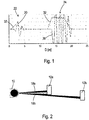
- FIG. 2 A first exemplary scenario is shown schematically in Fig. 2 shown.
- Fig. 2 There two emitted light pulses 18a, 18b are shown, which were emitted by a light transmitter of a distance-measuring monitoring sensor 10. While the light pulse 18a only strikes an object 12a that is closer to the monitoring sensor 10, the neighboring light pulse 18b strikes both the object 12a and an object 12b located behind it, further away from the monitoring sensor 10.
- a detection signal assigned to the light pulse 18b could approximately be the detection signal from Fig. 1 correspond. Accordingly, it would not be apparent from the detection signal itself whether the first received light pulse 22 originates from a non-critical occluding object or from a possibly safety-critical object 12a according to FIG Fig. 2 which was struck by part of the light pulse 18b in the area of an edge.
- a second test condition is used to check whether a comparison object was detected for at least one adjacent angle of rotation, the assigned received light pulse of which has essentially the same transit time as the first received light pulse.
- the transit time for the light pulse 18a completely remitted on the object 12a would be evaluated accordingly. Since both light pulses 18a, 18b strike the same object 12a, this test results in the illustrated case a truth value TRUE for the second test condition applied to the light pulse 18b. Accordingly, the distance for the current angle of rotation (corresponding to the light pulse 18b) must be determined on the basis of the transit time determined for the first received light pulse. It is thus ruled out that the object 12a is incorrectly treated as an occluding object that is not critical to safety and is not taken into account when determining the distance.
- a second exemplary scenario must be checked, which is shown in the schematic representation of Fig. 3 is represented.
- Fig. 3 shows one in an unscale way
- the light pulse 18 hits an object 12 almost completely and is remitted there as the first received light pulse 22 in the direction of the monitoring sensor 10.
- the scattered light 20 can pass the object 12 and partially strikes a reflector 14, in particular a retroreflector, which, viewed from the monitoring sensor 10, is located behind the object 12.
- the reflected scattered light generates a second received light pulse 24.
- the detection signal is similar to that in FIG Fig. 1 detection signal shown, the intensity ratios of the two received light pulses 22, 24 may differ.
- a reflector was detected for at least one adjacent angle of rotation, the assigned received light pulse of which has essentially the same transit time as the second received light pulse 24 Fig. 3
- a corresponding adjacent angle of rotation which is represented by a dashed arrow
- the corresponding received light pulse has the same transit time and accordingly also the same assigned distance as the second received light pulse 24. Since this received light pulse has a very high intensity due to the reflection on a (retro) reflector, it can also be determined by comparing the intensity with a reference value that this received light pulse must originate from a (retro) reflector.
- the second received light pulse 24 under consideration must then also originate from the (retro) reflector. Accordingly, the truth value TRUE can be assigned to the third test condition for the scenario shown here. Because of this, the distance must also be determined here on the basis of the transit time determined for the first received light pulse, ie the determined distance for the currently observed angle of rotation corresponds to the distance of the object 12 from the monitoring sensor 10.
- Fig. 4 a total of five different detection scenarios are shown again as an example, which are denoted by numbers from 1 to 5.
- a protective field 11 monitored by a monitoring sensor 10 is shown with a dashed boundary line.
- a background object 16 is located behind the protective field 11. This background object 16 can represent, for example, a stationary component of a machine to be monitored or a wall.
- occluding objects 17a, 17b shown as clouds, for example dust clouds which include objects or particles that are not critical to safety. Seen from the monitoring sensor 10, behind the occluding objects 17a, 17b, there are two safety-critical objects 12a, 12b.
- the received light pulses 22, 24 generated by the objects 12a, 12b, 16, 17a, 17b are represented by respective arrows, the intensity of the received light pulses 22, 24 being represented by the line width of the arrows (the stronger an arrow, the higher the intensity) .
- an emitted light pulse 18 only hits the occluding object 17a, so that the correspondingly generated detection signal has only a single received light pulse 22. Since this location is within protective field 11, a protective field violation is output as an alarm signal.
- the emitted light pulse 18 first strikes the occluding object 17a, which remits part of the light pulse 18 as the first received light pulse 22 and allows another part of the light pulse 18 to pass, which is remitted from the object 12a as the second received light pulse 24. Since neither an object edge nor a reflector was hit and the object 12a is located within the protective field 11, a protective field violation is detected for the second received light pulse 24.
- a relatively weak first received light pulse 22 is determined by the occluding object 17a and a relatively strong second received light pulse 24 is determined by the background object 16.
- a relatively strong second received light pulse 24 is determined by the background object 16.
- the background object 16 is located outside the protective field 11, no protective field violation is determined.
- the occluding object 17b generates a relatively strong first received light pulse 22 and the background object 16 a relatively weak second received light pulse 24 this transparency is recognized and the distance is determined on the basis of the second received light pulse. Since this in turn originates from the background object 16 and is therefore outside the protective field, the protective field is determined to be free.
- the monitoring sensor 10 detects a relatively strong first received light pulse 22 generated by the occluding object 17b and a very weak second received light pulse 24 generated by the object 12b Received light pulse 22 is too low, the distance is determined here on the basis of the first received light pulse 22. This leads to the detection of a protective field violation by the occluding object 17b.
- This scenario takes into account the fact that the transparency of the occluding object 17b is so low that it no longer lets through sufficient intensity to ensure reliable detection of an object 12b that may be behind it.
- the consideration of the absolute or relative intensities of the received light pulses 22, 24 and the comparison of the distances from the monitoring sensor 10 determined for a respective object with the predetermined limits of the protective field 11 represent further respective test conditions that can be additionally tested within the scope of the method according to the invention.
- FIG. 5 an exemplary sequence of the method according to the invention is explained in more detail using a flow chart.
- the method comprises two method sections 100, 200, which are carried out one after the other.
- the method described is used when at least one received light pulse is present in the received signal at a specific angle of rotation and, in this respect, an object in the protective field can be assumed, the distance of which is to be determined.
- a detection signal which represents a respective time profile of a received signal received by the light receiver for a respective angle of rotation, is provided in scanned form.
- a next step 120 the transit time or the corresponding distance for a first received light pulse of the detection signal is determined and supplied to a measurement data record 150.
- a further step 130 it is checked whether the detection signal has a second received light pulse. If this test condition is TRUE, the transit time or the assigned distance of the second received light pulse is determined in a further step 140. These possibly determined data are also fed to the measurement data record 150, with an additional, if necessary Flag can be added, which marks the measurement data set as "transparent".
- Steps 110 to 140 of first method section 100 can be carried out in an FPGA, for example.
- the measurement data record 150 is then processed further within the framework of the second method section 200.
- This method section 200 provides at least three test steps 210, 220, 230, with a respective test condition being or can be tested in each test step.
- the second method section 200 can be carried out, for example, in a signal processor.
- the first test step 210 it is checked whether the number of received light pulses is equal to one. If the first test condition tested in the first test step 210 is TRUE, a jump is made to a step 240.
- step 240 the distance is determined on the basis of the transit time determined for the first received light pulse.
- step 220 according to a second test condition, it is checked whether a comparison object was detected for at least one adjacent angle of rotation, the assigned received light pulse of which has essentially the same transit time as the first received light pulse. In other words, it is checked in the second test step whether there is an edge hit. If the second test condition is TRUE, step 240 is entered.
- a third test condition is used to test whether a reflector was detected for at least one adjacent angle of rotation, the assigned received light pulse of which has essentially the same transit time as the second received light pulse. In other words, it is checked here whether a reflector, in particular a retroreflector, is present in the background.
- step 240 is entered.
- step 250 the distance is determined on the basis of the transit time determined for the second received light pulse.
- Steps 240 or 250 can be followed by further method steps, for example determining a respective position of the detected object on the basis of the angle of rotation and the distance determined in accordance with step 240 or 250.
- the sequence of the test conditions checked in the second test step 220 and the third test step 230 can also be swapped, ie in the second test step 220 it is checked whether the Background a reflector is present and in the third test step 230 it is checked whether an edge hit is present.
- the first test condition can be checked in test step 210 not only by analyzing the measurement data record 150, in which (if necessary for the second time) the presence of a second received light pulse is checked and, if necessary, its assigned distance is determined, but alternatively or additionally also by Evaluation of the measurement data record 150 for the presence of the transparency flag.
- the FPGA and the signal processor can be in a control unit or an evaluation and control unit of the distance-measuring monitoring sensor 10 ( Figs. 2 to 4 ) be integrated.
- the test steps 210 to 230 can always be carried out independently of the outcome of a previous test step, the corresponding truth values of these tests being able to be stored in the measurement data record 150 in the form of respective flags, for example.
- the flags can then be evaluated, with a decision then being made on the basis of this evaluation as to whether step 240 or step 250 is to be carried out.
- Step 250 is only performed if all three truth values are FALSE, but if one or more of the truth values are TRUE, step 240 is always performed.
Claims (9)
- Procédé pour faire fonctionner un capteur de surveillance (10) de mesure de distance pour détecter et déterminer la position d'objets (12, 12a, 12b) dans un champ de protection (11) au moins bidimensionnel, le capteur de surveillance (10) comportant au moins un émetteur de lumière conçu pour émettre des impulsions lumineuses (18) dans le champ de protection (11), au moins un récepteur de lumière conçu pour recevoir, en tant qu'impulsions lumineuses de réception (22, 24), des impulsions lumineuses réfléchies ou renvoyées par au moins un objet (12, 12a, 12b) le cas échéant présent dans le champ de protection (11), et une unité de déviation conçue pour balayer périodiquement au moins le champ de protection (11) avec les impulsions lumineuses émises (18), la position respective dudit au moins un objet (12, 12a, 12b) pouvant être déterminée à partir d'un angle de rotation de l'unité de déviation et de la distance déterminée en fonction du temps de parcours d'une impulsion lumineuse de réception respective, comprenant les étapes consistant à :a) détecter un signal de détection respectif (30, 32) qui inclut une évolution temporelle respective d'un signal de réception reçu par le récepteur de lumière pour un angle de rotation respectif,b) déterminer le nombre d'impulsions lumineuses de réception (22, 24) incluses dans un signal de détection respectif (30, 32), où l'impulsion lumineuse de réception (22, 24) ayant le temps de parcours le plus court représente une première impulsion lumineuse de réception (22), et une impulsion lumineuse de réception (22, 24), le cas échéant présent, ayant un temps de parcours plus long représente une deuxième impulsion lumineuse de réception (24),c) générer un signal de détection pour un objet détecté respectif (12, 12a, 12b), le signal de détection incluant des informations sur la position déterminée de l'objet (12, 12a, 12b),caractérisé en ce que
le procédé comprend au moins les trois conditions de test suivantes, et la détermination de la position inclut la détermination de la distance en fonction d'une valeur de vérité logique respective de l'une au moins des conditions de test, sachant que- selon une première condition de test, on vérifie si le nombre d'impulsions lumineuses de réception (22, 24) dans un signal de réception respectif est égal à 1,- selon une deuxième condition de test, on vérifie si, pour au moins un angle de rotation voisin, un objet de comparaison a été détecté dont l'impulsion lumineuse de réception (22, 24) associée présente le même temps de parcours ou au moins sensiblement le même, c'est-à-dire dans le cadre de la précision de mesure du capteur de surveillance, que la première impulsion lumineuse de réception (22),- selon une troisième condition de test, on vérifie si, pour au moins un angle de rotation voisin, un réflecteur a été détecté dont l'impulsion lumineuse de réception (22, 24) associée présente le même temps de parcours ou au moins sensiblement le même, c'est-à-dire dans le cadre de la précision de mesure du capteur de surveillance, que la deuxième impulsion lumineuse de réception (24),dans lequel la première condition de test est vérifiée dans une première étape de test, soit la deuxième soit la troisième condition de test est vérifiée dans une deuxième étape de test effectuée le cas échéant, et la troisième ou la deuxième condition de test qui n'a pas été vérifiée jusqu'alors est vérifiée dans une troisième étape de test effectuée le cas échéant, et
dans lequel la détermination de la distance se fait sur la base du temps de parcours déterminé pour la deuxième impulsion lumineuse de réception (22, 24), si la valeur de vérité des première, deuxième et troisième conditions de test est FAUX, sinon elle se fait sur la base du temps de parcours déterminé pour la première impulsion lumineuse de réception (22, 24). - Procédé selon la revendication 1,
dans lequel d'autres conditions parmi les trois conditions de test ne sont plus vérifiées, si la valeur de vérité d'une condition de test précédemment vérifiée est VRAIE. - Procédé selon la revendication 1,
dans lequel tout d'abord les première, deuxième et troisième étapes de test sont effectuées, et dans une étape d'évaluation suivante, les valeurs de vérité des conditions de test associées sont évaluées, et
sur la base desdites conditions des valeurs de vérité, il est déterminé si la distance doit être déterminée sur la base du temps de parcours de la première ou de la deuxième impulsion lumineuse de réception (22, 24). - Procédé selon l'une des revendications précédentes,
dans lequel l'étape a) comprend la quantification du signal de détection (30, 32). - Procédé selon l'une des revendications précédentes,
dans lequel, dans une étape d) suivant l'étape c), un signal d'alarme ou un signal de coupure est émis lorsqu'au moins un signal de détection respectif satisfait à au moins une condition d'alarme prédéterminée. - Procédé selon l'une des revendications précédentes,dans lequel, dans l'étape b), la détermination du nombre d'impulsions lumineuses de réception (22, 24) inclut que, pour un ou plusieurs maxima locaux présents dans le signal de détection (30, 32), il est déterminé si un ou plusieurs critères nécessaires à l'identification en tant qu'impulsion lumineuse de réception (22, 24) sont satisfaits, etles critères sont choisis parmi un groupe comprenant une hauteur, une largeur et/ou une forme d'impulsion prédéterminées.
- Procédé selon l'une des revendications précédentes,
dans lequel la vérification de la troisième condition de test pour savoir si un réflecteur (14) a été détecté pour un angle de rotation voisin inclut l'évaluation de l'intensité d'une impulsion lumineuse de réception (22, 24) associée audit au moins un angle de rotation voisin, de préférence en la comparant à un seuil d'intensité prédéterminé de façon fixe ou dynamique. - Procédé selon l'une des revendications précédentes,
dans lequel le capteur de surveillance (10) est un scanner laser adapté pour surveiller une ou plusieurs surfaces de balayage. - Capteur de surveillance (10) de mesure de distance pour détecter et déterminer la position d'objets (12, 12a, 12b) dans un champ de protection (11) au moins bidimensionnel, dans lequel le capteur de surveillance (10) comprend au moins un émetteur de lumière, au moins un récepteur de lumière, une unité de déviation et une unité de commande, dans lequel l'unité de commande est adaptée pour mettre en oeuvre le procédé selon l'une des revendications précédentes.
Applications Claiming Priority (1)
| Application Number | Priority Date | Filing Date | Title |
|---|---|---|---|
| DE102019107681.1A DE102019107681B4 (de) | 2019-03-26 | 2019-03-26 | Verfahren zum Betreiben eines abstandsmessenden Überwachungssensors und abstandsmessender Überwachungssensor |
Publications (2)
| Publication Number | Publication Date |
|---|---|
| EP3715905A1 EP3715905A1 (fr) | 2020-09-30 |
| EP3715905B1 true EP3715905B1 (fr) | 2021-09-22 |
Family
ID=69804591
Family Applications (1)
| Application Number | Title | Priority Date | Filing Date |
|---|---|---|---|
| EP20162297.4A Active EP3715905B1 (fr) | 2019-03-26 | 2020-03-11 | Procédé de fonctionnement d'un capteur de surveillance de mesure de distance et capteur de surveillance de mesure de distance |
Country Status (6)
| Country | Link |
|---|---|
| US (1) | US11573308B2 (fr) |
| EP (1) | EP3715905B1 (fr) |
| JP (1) | JP6917497B2 (fr) |
| CN (1) | CN111830522B (fr) |
| DE (1) | DE102019107681B4 (fr) |
| DK (1) | DK3715905T3 (fr) |
Family Cites Families (13)
| Publication number | Priority date | Publication date | Assignee | Title |
|---|---|---|---|---|
| EP1619469B1 (fr) | 2004-07-22 | 2008-02-27 | Bea S.A. | Dispositif de balayage et détection à lumière pour détection autour des portes automatiques |
| US7944548B2 (en) * | 2006-03-07 | 2011-05-17 | Leica Geosystems Ag | Increasing measurement rate in time of flight measurement apparatuses |
| EP1860462A1 (fr) | 2006-05-23 | 2007-11-28 | Leica Geosystems AG | Procédé de mesure de distances et appareil de mesure de distances destinés à l'enregistrement des dimensions spatiales d'une cible |
| US7965384B2 (en) * | 2007-09-27 | 2011-06-21 | Omron Scientific Technologies, Inc. | Clutter rejection in active object detection systems |
| JP5092076B2 (ja) * | 2007-10-26 | 2012-12-05 | オプテックス株式会社 | レーザエリアセンサ |
| JP5540900B2 (ja) * | 2010-01-15 | 2014-07-02 | 株式会社デンソーウェーブ | レーザレーダ装置 |
| DE102010061382B4 (de) * | 2010-12-21 | 2019-02-14 | Sick Ag | Optoelektronischer Sensor und Verfahren zur Erfassung und Abstandsbestimmung von Objekten |
| JP5540217B2 (ja) | 2012-09-19 | 2014-07-02 | オプテックス株式会社 | レーザースキャンセンサ |
| DE102012112987B3 (de) * | 2012-12-21 | 2013-12-05 | Sick Ag | Optoelektronischer Sensor und Verfahren zur Erfassung und Abstandsbestimmung von Objekten |
| EP2998700B2 (fr) | 2014-09-18 | 2022-12-21 | Hexagon Technology Center GmbH | Dispositif de mesure de distance électro-optique et procédé de mesure de distance |
| US11585905B2 (en) * | 2016-05-03 | 2023-02-21 | Datalogic Ip Tech S.R.L. | Laser scanner |
| US10852438B2 (en) * | 2017-08-21 | 2020-12-01 | Caterpillar Inc. | LIDAR waveform classification |
| WO2019041269A1 (fr) | 2017-08-31 | 2019-03-07 | SZ DJI Technology Co., Ltd. | Étalonnage de temps de retard de dispositifs de mesure de distance optique et systèmes et procédés associés |
-
2019
- 2019-03-26 DE DE102019107681.1A patent/DE102019107681B4/de not_active Expired - Fee Related
-
2020
- 2020-03-11 EP EP20162297.4A patent/EP3715905B1/fr active Active
- 2020-03-11 DK DK20162297.4T patent/DK3715905T3/da active
- 2020-03-13 JP JP2020043609A patent/JP6917497B2/ja active Active
- 2020-03-24 US US16/828,469 patent/US11573308B2/en active Active
- 2020-03-24 CN CN202010213639.3A patent/CN111830522B/zh active Active
Also Published As
| Publication number | Publication date |
|---|---|
| DE102019107681A1 (de) | 2020-10-01 |
| JP6917497B2 (ja) | 2021-08-11 |
| JP2020160063A (ja) | 2020-10-01 |
| US20200309924A1 (en) | 2020-10-01 |
| US11573308B2 (en) | 2023-02-07 |
| DK3715905T3 (da) | 2021-10-25 |
| EP3715905A1 (fr) | 2020-09-30 |
| CN111830522A (zh) | 2020-10-27 |
| CN111830522B (zh) | 2022-11-01 |
| DE102019107681B4 (de) | 2022-12-01 |
Similar Documents
| Publication | Publication Date | Title |
|---|---|---|
| EP2541273B1 (fr) | Détection et détermination de distance d'objets | |
| EP2942645B1 (fr) | Capteur télémétrique et procédé destiné à la détection et la détermination de l'éloignement d'objets | |
| EP2824478B1 (fr) | Capteur optoélectronique et procédé destiné à la détection d'objets et à la détermination de distance dans une zone de surveillance | |
| DE102010061382B4 (de) | Optoelektronischer Sensor und Verfahren zur Erfassung und Abstandsbestimmung von Objekten | |
| DE102012112987B3 (de) | Optoelektronischer Sensor und Verfahren zur Erfassung und Abstandsbestimmung von Objekten | |
| EP3435117B1 (fr) | Capteur et procédé de détection et de détermination des distances entre des objets | |
| DE102009057104B4 (de) | Entfernungsmessender Laserscanner | |
| EP3220164B1 (fr) | Procédé de fonctionnement d'un capteur écartométrique de surveillance et capteur écartométrique de surveillance | |
| EP3557286B1 (fr) | Capteur optoélectronique et procédé de détection et de détermination de distance d'un objet | |
| EP3232224B1 (fr) | Capteur telemetrique optoelectronique et procede de detection et de determination de distances entre des objets | |
| EP3287809B1 (fr) | Procédé de fonctionnement d'un dispositif de baleyage et dispositif de baleyage | |
| DE10313194B4 (de) | Optoelektronische Vorrichtung und Verfahren zur Erfassung von Objekten mittels eines optischen Sensors | |
| EP2735887B1 (fr) | Dispositif d'enregistrement optique | |
| EP2703837B1 (fr) | Scanner laser de sécurité | |
| EP3715905B1 (fr) | Procédé de fonctionnement d'un capteur de surveillance de mesure de distance et capteur de surveillance de mesure de distance | |
| EP3588139B1 (fr) | Capteur optoélectronique et procédé de détermination de la distance | |
| WO2019101506A1 (fr) | Procédé de fonctionnement d'un capteur lidar et capteur lidar | |
| DE202012105044U1 (de) | Optoelektronischer Sensor zur Erfassung und Abstandsbestimmung von Objekten | |
| EP4162299A1 (fr) | Procédé et dispositif d'identification d'une contamination sur un écran de protection d'un capteur lidar | |
| DE202012103344U1 (de) | Sicherheits-Lichtscanner | |
| DE102010064682B3 (de) | Optoelektronischer Sensor und Verfahren zur Erfassung und Abstandsbestimmung von Objekten | |
| EP3663796B1 (fr) | Procédé de détermination d'une distance | |
| EP2287630B1 (fr) | Dispositif de saisie optoélectronique | |
| EP4306998A1 (fr) | Capteur optique | |
| DE202021103966U1 (de) | Optoelektronischer Sensor zur Erfassung von Objekten |
Legal Events
| Date | Code | Title | Description |
|---|---|---|---|
| PUAI | Public reference made under article 153(3) epc to a published international application that has entered the european phase |
Free format text: ORIGINAL CODE: 0009012 |
|
| STAA | Information on the status of an ep patent application or granted ep patent |
Free format text: STATUS: THE APPLICATION HAS BEEN PUBLISHED |
|
| AK | Designated contracting states |
Kind code of ref document: A1 Designated state(s): AL AT BE BG CH CY CZ DE DK EE ES FI FR GB GR HR HU IE IS IT LI LT LU LV MC MK MT NL NO PL PT RO RS SE SI SK SM TR |
|
| AX | Request for extension of the european patent |
Extension state: BA ME |
|
| STAA | Information on the status of an ep patent application or granted ep patent |
Free format text: STATUS: REQUEST FOR EXAMINATION WAS MADE |
|
| 17P | Request for examination filed |
Effective date: 20210222 |
|
| RBV | Designated contracting states (corrected) |
Designated state(s): AL AT BE BG CH CY CZ DE DK EE ES FI FR GB GR HR HU IE IS IT LI LT LU LV MC MK MT NL NO PL PT RO RS SE SI SK SM TR |
|
| GRAP | Despatch of communication of intention to grant a patent |
Free format text: ORIGINAL CODE: EPIDOSNIGR1 |
|
| STAA | Information on the status of an ep patent application or granted ep patent |
Free format text: STATUS: GRANT OF PATENT IS INTENDED |
|
| RIC1 | Information provided on ipc code assigned before grant |
Ipc: G01S 17/931 20200101ALI20210415BHEP Ipc: G01S 17/88 20060101ALI20210415BHEP Ipc: G01S 17/06 20060101ALI20210415BHEP Ipc: G01S 7/487 20060101ALI20210415BHEP Ipc: G01S 7/4865 20200101ALI20210415BHEP Ipc: G01S 7/481 20060101AFI20210415BHEP |
|
| INTG | Intention to grant announced |
Effective date: 20210510 |
|
| GRAS | Grant fee paid |
Free format text: ORIGINAL CODE: EPIDOSNIGR3 |
|
| GRAA | (expected) grant |
Free format text: ORIGINAL CODE: 0009210 |
|
| STAA | Information on the status of an ep patent application or granted ep patent |
Free format text: STATUS: THE PATENT HAS BEEN GRANTED |
|
| AK | Designated contracting states |
Kind code of ref document: B1 Designated state(s): AL AT BE BG CH CY CZ DE DK EE ES FI FR GB GR HR HU IE IS IT LI LT LU LV MC MK MT NL NO PL PT RO RS SE SI SK SM TR |
|
| REG | Reference to a national code |
Ref country code: GB Ref legal event code: FG4D Free format text: NOT ENGLISH |
|
| REG | Reference to a national code |
Ref country code: DE Ref legal event code: R096 Ref document number: 502020000200 Country of ref document: DE |
|
| REG | Reference to a national code |
Ref country code: IE Ref legal event code: FG4D Free format text: LANGUAGE OF EP DOCUMENT: GERMAN |
|
| REG | Reference to a national code |
Ref country code: CH Ref legal event code: EP Ref country code: AT Ref legal event code: REF Ref document number: 1432745 Country of ref document: AT Kind code of ref document: T Effective date: 20211015 |
|
| REG | Reference to a national code |
Ref country code: DK Ref legal event code: T3 Effective date: 20211022 |
|
| REG | Reference to a national code |
Ref country code: LT Ref legal event code: MG9D |
|
| REG | Reference to a national code |
Ref country code: NL Ref legal event code: MP Effective date: 20210922 |
|
| PG25 | Lapsed in a contracting state [announced via postgrant information from national office to epo] |
Ref country code: BG Free format text: LAPSE BECAUSE OF FAILURE TO SUBMIT A TRANSLATION OF THE DESCRIPTION OR TO PAY THE FEE WITHIN THE PRESCRIBED TIME-LIMIT Effective date: 20211222 Ref country code: LT Free format text: LAPSE BECAUSE OF FAILURE TO SUBMIT A TRANSLATION OF THE DESCRIPTION OR TO PAY THE FEE WITHIN THE PRESCRIBED TIME-LIMIT Effective date: 20210922 Ref country code: NO Free format text: LAPSE BECAUSE OF FAILURE TO SUBMIT A TRANSLATION OF THE DESCRIPTION OR TO PAY THE FEE WITHIN THE PRESCRIBED TIME-LIMIT Effective date: 20211222 Ref country code: HR Free format text: LAPSE BECAUSE OF FAILURE TO SUBMIT A TRANSLATION OF THE DESCRIPTION OR TO PAY THE FEE WITHIN THE PRESCRIBED TIME-LIMIT Effective date: 20210922 Ref country code: FI Free format text: LAPSE BECAUSE OF FAILURE TO SUBMIT A TRANSLATION OF THE DESCRIPTION OR TO PAY THE FEE WITHIN THE PRESCRIBED TIME-LIMIT Effective date: 20210922 Ref country code: RS Free format text: LAPSE BECAUSE OF FAILURE TO SUBMIT A TRANSLATION OF THE DESCRIPTION OR TO PAY THE FEE WITHIN THE PRESCRIBED TIME-LIMIT Effective date: 20210922 Ref country code: SE Free format text: LAPSE BECAUSE OF FAILURE TO SUBMIT A TRANSLATION OF THE DESCRIPTION OR TO PAY THE FEE WITHIN THE PRESCRIBED TIME-LIMIT Effective date: 20210922 |
|
| PG25 | Lapsed in a contracting state [announced via postgrant information from national office to epo] |
Ref country code: LV Free format text: LAPSE BECAUSE OF FAILURE TO SUBMIT A TRANSLATION OF THE DESCRIPTION OR TO PAY THE FEE WITHIN THE PRESCRIBED TIME-LIMIT Effective date: 20210922 Ref country code: GR Free format text: LAPSE BECAUSE OF FAILURE TO SUBMIT A TRANSLATION OF THE DESCRIPTION OR TO PAY THE FEE WITHIN THE PRESCRIBED TIME-LIMIT Effective date: 20211223 |
|
| PG25 | Lapsed in a contracting state [announced via postgrant information from national office to epo] |
Ref country code: IS Free format text: LAPSE BECAUSE OF FAILURE TO SUBMIT A TRANSLATION OF THE DESCRIPTION OR TO PAY THE FEE WITHIN THE PRESCRIBED TIME-LIMIT Effective date: 20220122 Ref country code: SK Free format text: LAPSE BECAUSE OF FAILURE TO SUBMIT A TRANSLATION OF THE DESCRIPTION OR TO PAY THE FEE WITHIN THE PRESCRIBED TIME-LIMIT Effective date: 20210922 Ref country code: RO Free format text: LAPSE BECAUSE OF FAILURE TO SUBMIT A TRANSLATION OF THE DESCRIPTION OR TO PAY THE FEE WITHIN THE PRESCRIBED TIME-LIMIT Effective date: 20210922 Ref country code: PT Free format text: LAPSE BECAUSE OF FAILURE TO SUBMIT A TRANSLATION OF THE DESCRIPTION OR TO PAY THE FEE WITHIN THE PRESCRIBED TIME-LIMIT Effective date: 20220124 Ref country code: PL Free format text: LAPSE BECAUSE OF FAILURE TO SUBMIT A TRANSLATION OF THE DESCRIPTION OR TO PAY THE FEE WITHIN THE PRESCRIBED TIME-LIMIT Effective date: 20210922 Ref country code: NL Free format text: LAPSE BECAUSE OF FAILURE TO SUBMIT A TRANSLATION OF THE DESCRIPTION OR TO PAY THE FEE WITHIN THE PRESCRIBED TIME-LIMIT Effective date: 20210922 Ref country code: ES Free format text: LAPSE BECAUSE OF FAILURE TO SUBMIT A TRANSLATION OF THE DESCRIPTION OR TO PAY THE FEE WITHIN THE PRESCRIBED TIME-LIMIT Effective date: 20210922 Ref country code: EE Free format text: LAPSE BECAUSE OF FAILURE TO SUBMIT A TRANSLATION OF THE DESCRIPTION OR TO PAY THE FEE WITHIN THE PRESCRIBED TIME-LIMIT Effective date: 20210922 Ref country code: CZ Free format text: LAPSE BECAUSE OF FAILURE TO SUBMIT A TRANSLATION OF THE DESCRIPTION OR TO PAY THE FEE WITHIN THE PRESCRIBED TIME-LIMIT Effective date: 20210922 Ref country code: AL Free format text: LAPSE BECAUSE OF FAILURE TO SUBMIT A TRANSLATION OF THE DESCRIPTION OR TO PAY THE FEE WITHIN THE PRESCRIBED TIME-LIMIT Effective date: 20210922 |
|
| REG | Reference to a national code |
Ref country code: DE Ref legal event code: R097 Ref document number: 502020000200 Country of ref document: DE |
|
| PLBE | No opposition filed within time limit |
Free format text: ORIGINAL CODE: 0009261 |
|
| STAA | Information on the status of an ep patent application or granted ep patent |
Free format text: STATUS: NO OPPOSITION FILED WITHIN TIME LIMIT |
|
| 26N | No opposition filed |
Effective date: 20220623 |
|
| PG25 | Lapsed in a contracting state [announced via postgrant information from national office to epo] |
Ref country code: MC Free format text: LAPSE BECAUSE OF FAILURE TO SUBMIT A TRANSLATION OF THE DESCRIPTION OR TO PAY THE FEE WITHIN THE PRESCRIBED TIME-LIMIT Effective date: 20210922 |
|
| PG25 | Lapsed in a contracting state [announced via postgrant information from national office to epo] |
Ref country code: SI Free format text: LAPSE BECAUSE OF FAILURE TO SUBMIT A TRANSLATION OF THE DESCRIPTION OR TO PAY THE FEE WITHIN THE PRESCRIBED TIME-LIMIT Effective date: 20210922 |
|
| REG | Reference to a national code |
Ref country code: BE Ref legal event code: MM Effective date: 20220331 |
|
| PG25 | Lapsed in a contracting state [announced via postgrant information from national office to epo] |
Ref country code: LU Free format text: LAPSE BECAUSE OF NON-PAYMENT OF DUE FEES Effective date: 20220311 Ref country code: IE Free format text: LAPSE BECAUSE OF NON-PAYMENT OF DUE FEES Effective date: 20220311 |
|
| PG25 | Lapsed in a contracting state [announced via postgrant information from national office to epo] |
Ref country code: BE Free format text: LAPSE BECAUSE OF NON-PAYMENT OF DUE FEES Effective date: 20220331 |
|
| PGFP | Annual fee paid to national office [announced via postgrant information from national office to epo] |
Ref country code: FR Payment date: 20230320 Year of fee payment: 4 Ref country code: DK Payment date: 20230323 Year of fee payment: 4 |
|
| PGFP | Annual fee paid to national office [announced via postgrant information from national office to epo] |
Ref country code: DE Payment date: 20230320 Year of fee payment: 4 |
|
| PGFP | Annual fee paid to national office [announced via postgrant information from national office to epo] |
Ref country code: IT Payment date: 20230331 Year of fee payment: 4 |
|
| REG | Reference to a national code |
Ref country code: CH Ref legal event code: PL |
|
| PG25 | Lapsed in a contracting state [announced via postgrant information from national office to epo] |
Ref country code: LI Free format text: LAPSE BECAUSE OF NON-PAYMENT OF DUE FEES Effective date: 20230331 Ref country code: CH Free format text: LAPSE BECAUSE OF NON-PAYMENT OF DUE FEES Effective date: 20230331 |